

Electrolux Professional EI30ES55LB, EW30IS65JS, EW30ES65GS Installation Manual
INSTALLATION INSTRUCTIONS
30" ELECTRIC SLIDE-IN RANGE
United States
INSTALLATION AND SERVICE MUST BE PERFORMED BY A
QUALIFIED INSTALLER.
IMPORTANT: SAVE FOR LOCAL ELECTRICAL INSPECTOR'S USE.
READ AND SAVE THESE INSTRUCTIONS FOR FUTURE REFERENCE.
FOR YOUR SAFETY: Do not store or use gasoline or other
flammable vapors and liquids in the vicinity of this or any other appliance.
Table of Contents
Important Safety Instructions ...................................2
Cutout Dimensions ...............................................3-4
To Avoid Breakage ...................................................5
Factory Connected Power Supply Cord ....................6
Power Supply Kit ......................................................6
Access to Terminal Block & Grounding Strap ............6
Serial Plate Location .................................................6
Important Notes to the Installer
1. Read all instructions contained in these installation
instructions before installing range.
2. Remove all packing material from the oven and
the drawer compartments before connecting the
electrical supply to the range.
3. Observe all governing codes and ordinances.
4. Be sure to leave these instructions with the
consumer.
Canada
Electrical Connection to the Range ........................7-8
Cabinet Construction ............................................... 9
Range Installation ..................................................10
Leveling the range .................................................11
Check Operation ....................................................11
Anti-Tip Brackets Installation ..................................12
Important Note to the Consumer
Keep these instructions with your owner's guide for
future reference.
Printed in Canada
P/N 318201626 (1212) Rev. C
English – pages 1-12
Español – páginas 13-24
Français – pages 25-36
30" ELECTRIC SLIDE-IN RANGE INSTALLATION INSTRUCTIONS
IMPORTANT SAFETY INSTRUCTIONS
This manual contains important safety symbols and instructions. Please pay attention to these symbols and
follow all instructions given.
This symbol will help alert you to situations that may cause serious bodily harm, death or
property damage.
This symbol will help alert you to situations that may cause bodily injury or property
damage.
Cold temperatures can damage the
electronic control. When using the appliance for the
first time, or when the appliance has not been used
for an extended period of time, be certain the unit has
been in temperatures above 32°F (0°C) for at least 3
hours before turning on the power to the appliance.
• Be sure your range is installed and grounded
properly by a qualified installer or service
technician.
•This range must be electrically grounded in
accordance with local codes or, in their absence,
with the National Electrical Code ANSI/NFPA No.
70—latest edition in United States or with CSA
Standard C22.1, Canadian Electrical Code, Part 1
in Canada.
•Theinstallationofappliancesdesignedfor
manufactured (mobile) home installation must
conform with Manufactured Home Construction and
Safety Standard, title 24CFR, part 3280 [Formerly
the Federal Standard for Mobile Home Construction
and Safety, title 24, HUD (part 280)] or when
such standard is not applicable, the Standard for
Manufactured Home Installation 1982 (Manufactured
Home Sites, Communities and Setups), ANSI Z225.1/
NFPA 501A-latest edition, or with local codes in
United States and with CAN/CSA-Z240 MH in
Canada.
•Make sure the wall coverings around the range
can withstand the heat generated by the range.
•Before installing the range in an area covered
with linoleum or any other synthetic floor
covering, make sure the floor covering can
withstand heat at least 90°F (32.2°C) above room
temperature without shrinking, warping or
discoloring. Do not install the range over carpeting
unless you place an insulating pad or sheet of ¼"
(0.64 cm) thick plywood between the range and
carpeting.
Never leave children alone or
unattended in the area where an appliance is in
use. As children grow, teach them the proper, safe use
of all appliances. Never leave the oven door open when
the range is unattended.
Stepping, leaning or sitting on the
door or drawer of this range can result in serious
injuries and can also cause damage to the range.
•Do not store items of interest to children in
the cabinets above the range. Children could be
seriously burned climbing on the range to reach items.
•To eliminate the risk of burns or fire by reaching
over heated surface units, cabinet storage
space above the surface unit should be avoided.
If cabinet storage is to be provided the risk can
be reduce by installing a range hood that project
horizontally a minimum of 5 inches beyond the bottom
of the cabinet.
•Do not use the oven as a storage space. This
creates a potentially hazardous situation.
•Never use your range for warming or heating the
room. Prolonged use of the range without adequate
ventilation can be dangerous.
•Do not store or use gasoline or other flammable
vapors and liquids near this or any other
appliance. Explosions or fires could result.
•Reset all controls to the "off" position after using
a programmable timing operation.
FOR MODELS WITH SELF-CLEAN FEATURE:
•Remove oven racks, broiler pan, food and other
utensils before self-cleaning the oven. Wipe up
excess spillage. Follow the precleaning instructions in
the Owner's Guide.
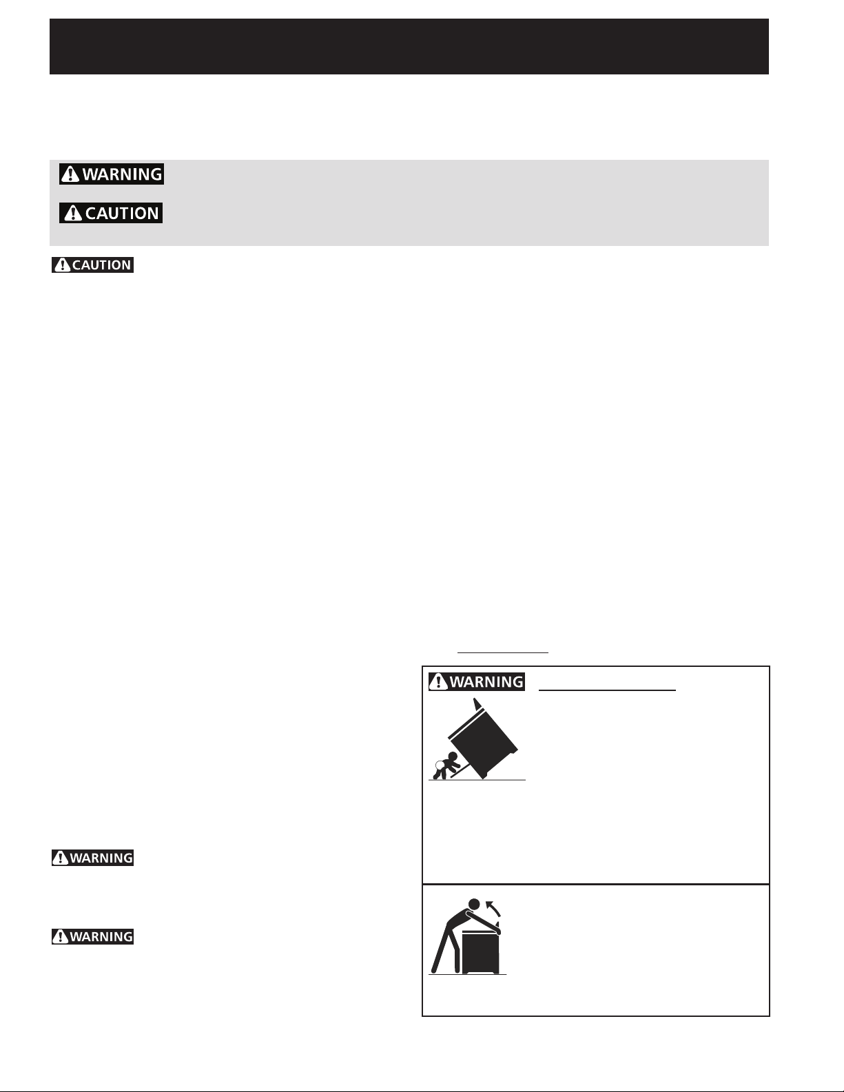
Tip Over Hazard
A child or adult can tip the range •
and be killed.
Verify the anti-tip device has been •
installed to floor or wall as per
installation instructions.
Ensure the anti-tip device is re-engaged to floor •
or wall when the range is moved.
Do not operate the range without the anti-tip •
device in place and engaged.
Failure to follow these instructions can result in •
death or serious burns to children and adults.
To check if the anti-tip bracket is
installed properly, use both arms
and grasp the rear edge of range
back. Carefully attempt to tilt range
forward. When properly installed, the
range should not tilt forward.
Refer to the anti-tip bracket installation instructions
supplied with your range for proper installation.
2
30" ELECTRIC SLIDE-IN RANGE INSTALLATION INSTRUCTIONS
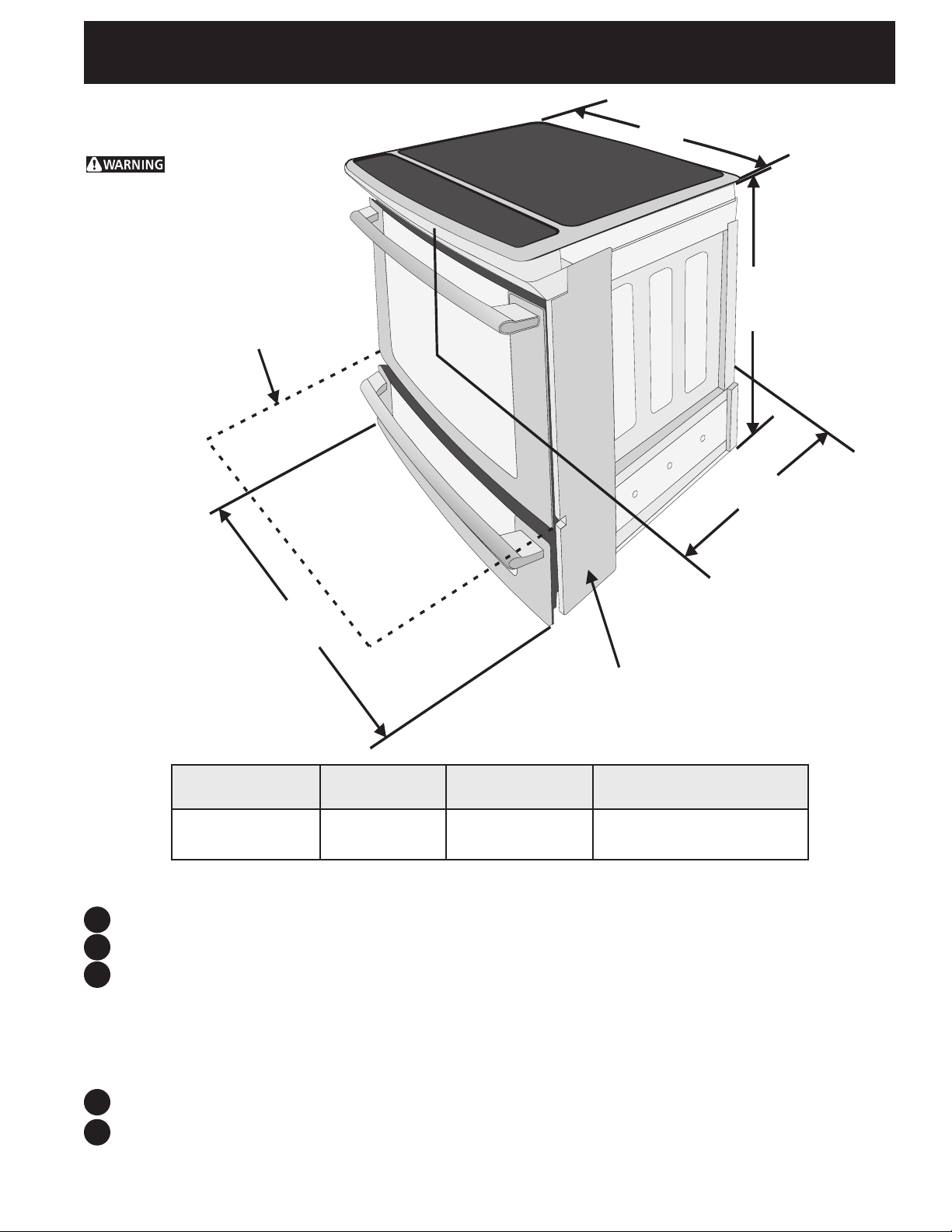
A
D
C
B
Product Dimensions
Do not
install the unit in the
cabinet before reading
next two pages.
Open Door
(see note 5)
Side Panel
A. HEIGHT
(Under Cooktop)
35 3/4" (90,8 cm)
36 5/8" (93 cm)
B. WIDTH
30" (76,2 cm) 31 1/2" (80 cm) 28 5/16" (71,9 cm)
NOTE:
Do not pinch the power supply cord or the flexible gas conduit between the range and the wall.
1
Do not seal the range to the side cabinets.
2
24" (61 cm) minimum clearance between the cooktop and the bottom of the cabinet when the
3
bottom of wood or metal cabinet is protected by not less than ¼" (0,64 cm) flame retardant
millboard covered with not less than No. 28 MSG sheet metal, 0,015"(0,4 mm) stainless steel,
0,024"(0,6 mm) aluminum, or 0,020" (0,5 mm) copper.
C. COOKTOP
WIDTH
D. TOTAL DEPTH TO FRONT
OF RANGE
30" (76,2 cm) minimum clearance when the cabinet is unprotected.
4
For cutouts below 22 7/8"(58,1 cm), appliance will slightly show out of the cabinet.
Allow at least 19 ¼" (48,9 cm) clearance for door depth when it is open.
5
3
30" ELECTRIC SLIDE-IN RANGE INSTALLATION INSTRUCTIONS
G
E
½”
min.
3/8”
min.
½”min.
13/16”min.
4 1/4”min.
1/8”min.
1 5/8
”
min.
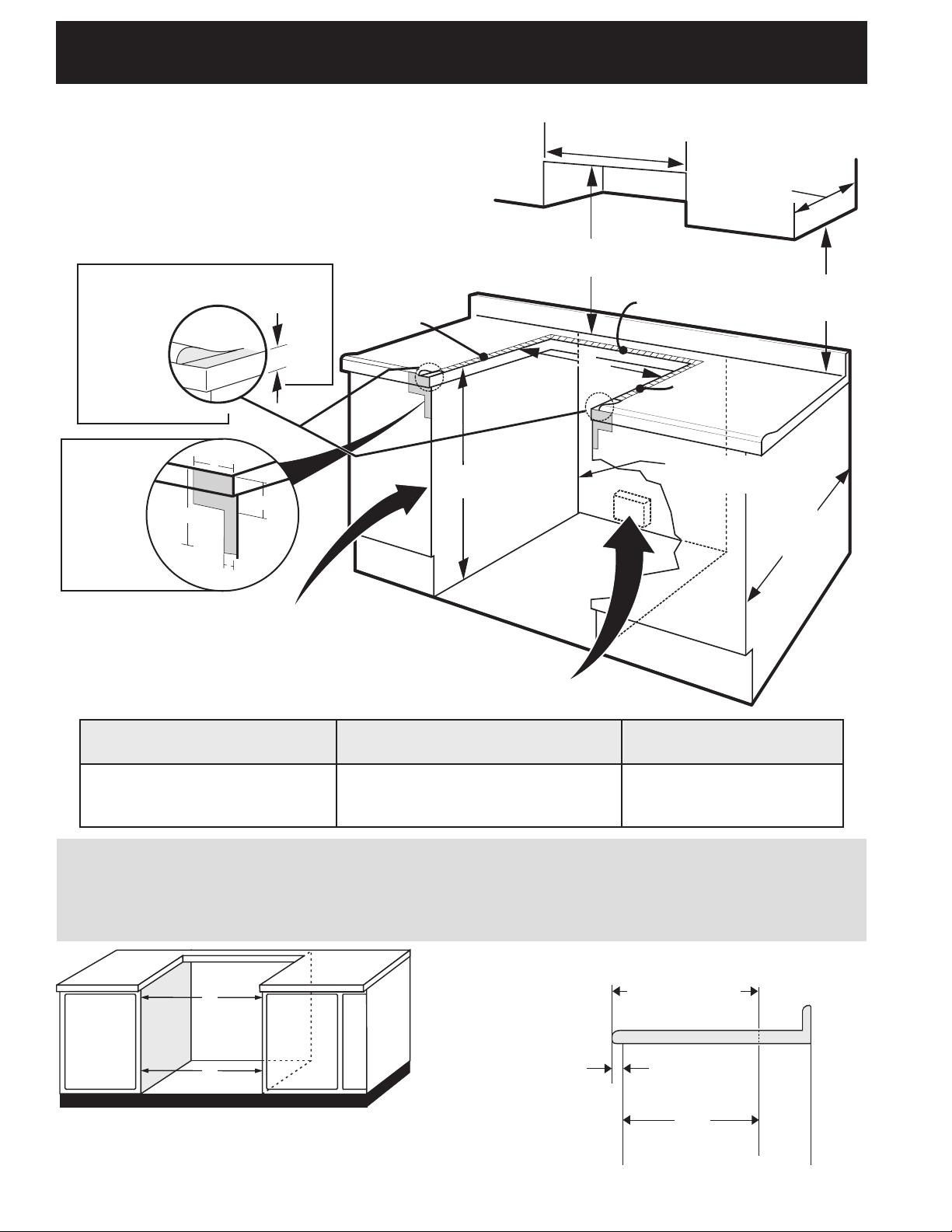
Cabinet Dimensions
Shave Raised
Edge To Clear
Space for
31 1/2"
(80 cm)
Wide
Cooktop Rim.
Shaded
area shall
be clear
of any
openable
panel or
drawer.
1 ½" Max.
(3,8 cm Max.)
Countertop
hatched surfaces
should be flat &
leveled.
30" Min.
(76,2 cm) Min.
13"
(33 cm)
30" Min. (see Note 3)
(76,2 cm) Min. (See Note 3)
18" Min.
(45,7 cm) Min.
Approx. 1 7/8"
(4,8 cm)
24" Min.
(61 cm) Min.
Locate Cabinet Doors 1" (2,5 cm)
Min. From Cutout Opening
Grounded Junction Box or Wall Outlet Should Be
Located 8" to 17" (20,3 - 43,2 cm) From Right
Cabinet and 2" to 4" (5,1-10,2 cm) From Floor
E. CUTOUT WIDTH
(Countertop and cabinet)***
30±1/16"
(76,2±0,15 cm)
E
***IMPORTANT: To avoid cooktop breakage for cutout width (E dimension) of more than 30 1/16" (76,4
cm), make sure the appliance is centered in the counter opening while pushing into it. Raise leveling
legs and the rear adjustable wheels at a higher position than the cabinet height (see page 5), insert
the appliance in the counter and then level. Make sure the unit is supported by the leveling legs at the
front and the wheels at the back and NOT by the cooktop itself.
24" (61 cm) Min. with backguard
F. CUTOUT DEPTH
21 3/4" (55,2 cm) Min.
22 1/8" (56,2 cm) Max
22 7/8"(58,1 cm) min.
23 1/4"(59,05 cm) max.
(see Note 4)
E
IMPORTANT: Cabinet and countertop
width should match the cutout width.
FRONT OF
CABINET
G. HEIGHT
OF COUNTERTOP
35 7/8" (91,1 cm) Min.
36 5/8" (93 cm) Max.
1 1/8"
(2,86 cm)
F
Ref.
4

30" ELECTRIC SLIDE-IN RANGE INSTALLATION INSTRUCTIONS
H1
H2
H3
H4
To avoid breakage: Do NOT handle or
manipulate the unit by the cooktop.
The counter-top around the cut-out should be flat and
1
leveled (see hatched area on illustration 1).
Before installing the unit, measure the heights of the two (2)
cabinet sides (H1-4), front and back (see illustration 1) from the
2
floor to the top of the counter.
Level the range using
the two (2) front leveling
legs and the two (2)
adjustable leveling wheel,
3
so that the height from
the floor to the underside
Shave
Raised
Edge
to Clear
Space for a
31½" (81 cm)
Wide Cooktop.
of the metal flange is
greater than the tallest cabinet measurement by
at least 1/16" (see illustration 2).
Remove and discard the two rear leveling legs,
4
they are only in place to solidify the unit for the transport.
1 ½" Max.
(3.8 cm Max.)
Illustration 1
Slide the unit into the cabinet. Make sure the center of the unit is
5
aligned with the center of the cabinet cut-out.
Remove the protective channels on each side of the cooktop
6
(if provided).
The metal flange under each side of the cooktop MUST be
placed over the cabinet countertop for proper unit support.
The cooktop should NOT rest directly on the countertop (see
7
illustration 2) or else it could cause damage to the cooktop
voiding the warranty. Level the unit if needed.
After the installation, MAKE SURE that the
unit is supported by the two front leveling
8
legs and the two adjustable leveling wheels
and NOT by the cooktop.
Metal
Flange
To successfully install
the range, the initial
level height from
floor to underside
of cooktop frame
should be at least
1/16" taller than
cabin e t sides as
measured in step 2.
Illustration 2
5

30" ELECTRIC SLIDE-IN RANGE INSTALLATION INSTRUCTIONS
1. Factory Connected Power Supply
Cord (Canada only)
This range is equipped with a factory-connected power
cord (see Figure 1). Cord must be connected to a
grounded 120/240 volt or 120/208 volt range outlet. If
no outlet is available, have one installed by a qualified
electrician.
Canada Style
Figure 1
2. Power Supply Cord Kit (U.S.A.)
The user is responsible for connecting the power supply
cord to the connection block located behind the back
panel access cover.
This appliance may be connected by means of
permanent "hard wiring"; flexible armored or
nonmetallic shielded copper cable (when local code
allow it) or by means of a power supply cord kit.
NOTE: Electric Slide-in Range is shipped from factory
with 1 1/8" (2.9 cm) dia. hole as shown on figure 4. If a
larger hole is required, punch out the knockout.
Risk of fire or electrical shock exists
if an incorrect size range cord kit is used, the
Installation Instructions are not followed, or the
strain relief bracket is discarded.
For mobile homes, new installations or recreational
vehicles, use only a power supply kit designed for a
range at 125V/250V 50A recommended (minimum
40A). Cord must have either 3 (when local code permits
grounding through neutral) or 4 conductors. Terminal on
end of wires must be either closed loop or open spade
lug with upturned ends. Cord must have strain-relief
clamp.
Do not loosen the nuts which secure
the factory-installed range wiring to terminal block
while connecting range. Electrical failure or loss of
electrical connection may occur.
Electrical Shock Hazard
•Electricalgroundisrequiredonthisappliance.
•Donotconnecttotheelectricalsupplyuntil
appliance is permanently grounded.
•Disconnectpowertothecircuitbreakerorfuse
box before making the electrical connection.
•Thisappliancemustbeconnectedtoa
grounded, metallic, permanent wiring system,
or a grounding connector should be connected
to the grounding terminal or wire lead on the
appliance.
Failure to do any of the above could result in a
fire, personal injury or electrical shock.
3. Access to Terminal Block &
Grounding Strap (U.S.A.)
BEND REAR WIRE COVER HERE
FOR ACCESS TO TERMINAL BLOCK
Figure 2
This appliance is manufactured with
the frame grounded by connection of a grounding
strap between the neutral power supply terminal
and the frame. If used in USA, in a new branch
circuit installation (1996 NEC), mobile home or
recreational vehicule, where local code do not
permit grounding through neutral (white) wire
or in Canada; remove the grounding strap from
the frame and cut the other end, near the neutral
terminal. Connect the appliance in usual manner.
Serial Plate Location
You will find the model and serial
number printed on the serial
plate. The serial plate is located as
shown.
Remember to record the serial
number for future reference.
6
30" ELECTRIC SLIDE-IN RANGE INSTALLATION INSTRUCTIONS
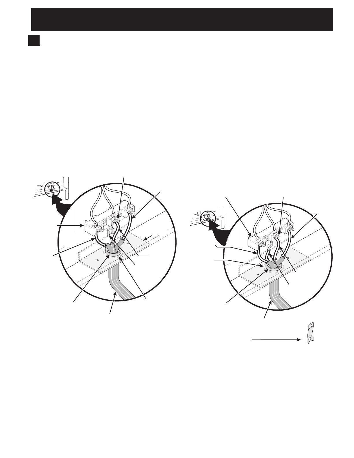
4. Electrical Connection to the Range
(U.S.A.)
Three Conductor Wire Connection to Range
If local codes permit connection of the frame grounding
conductor to the neutral wire of the copper power
supply cord (see Figure 3):
1. Remove the 3 screws at the lower end of the rear
wire cover, then bend the lower end of the rear
wire cover (access cover) upward to expose range
terminal connection block (see Figure 2).
2. Using the nuts supplied in the literature package,
connect the neutral of the copper power supply cord
to the center silver-colored terminal of the terminal
block, and connect the other wires to the outer
terminals. Match wires and terminals by color (red
wires connected to the right terminal, black wires
connected to the left terminal) (see figure 3).
3. Lower the terminal cover and replace the 3 screws.
Silver Colored Terminal
Red Wire
Terminal
Block
Cord
Mounting
Plate
Four Conductor Wire Connection to Range
Where local codes does NOT permit connection of the
frame grounding conductor to the neutral wire of the
copper power supply cord (see Figure 4):
1. Remove the 3 screws at the lower end of the rear
wire cover, then raise the lower end of the rear
wire cover (access cover) upward to expose range
terminal connection block (see figure 2).
2. Remove the grounding strap from the terminal block
and from the appliance frame.
3. Using the nuts supplied with the literature package,
connect the ground wire (green) of the copper
power supply cord to the frame of the appliance
with the ground screw, using the hole in the frame
where the ground strap was removed (see Figure 4).
4. Connect the neutral of the copper power supply
cord to the center silver-colored terminal of the
terminal block, and connect the other wires to the
outer terminals. Match wires and terminals by color
(red wires connected to the right terminal, black
wires connected to the left terminal).
5. Lower the terminal cover and replace the 3 screws.
Terminal Block Silver Colored Terminal
Red
Wire
Black
Wire
A User Supplied
Strain-relief Must
Be Installed at This
Location.
To 240 V
Receptacle
Figure 3
Neutral
(White Wire)
Grounding
Strap
1 1/8" (2.9 cm) Dia.
Direct Connection
Hole. Punch Out
Knockout for 1 3/8"
(3.5 cm) Dia. Cord
Kit Hole.
Black Wire
1 1/8" (2.9cm)
Dia. Direct
Connection
Hole. Punch
Out Knockout
for 1 3/8"
(3.5cm) Dia.
Cord Kit Hole.
A User Supplied
Strain-relief Must
Be Installed at This
Location
NOTE: Be sure to remove the
supplied grounding strap.
To 240 V Receptacle
Figure 4
Neutral
(White Wire)
Ground (Bare
Copper Wire)
7
30" ELECTRIC SLIDE-IN RANGE INSTALLATION INSTRUCTIONS
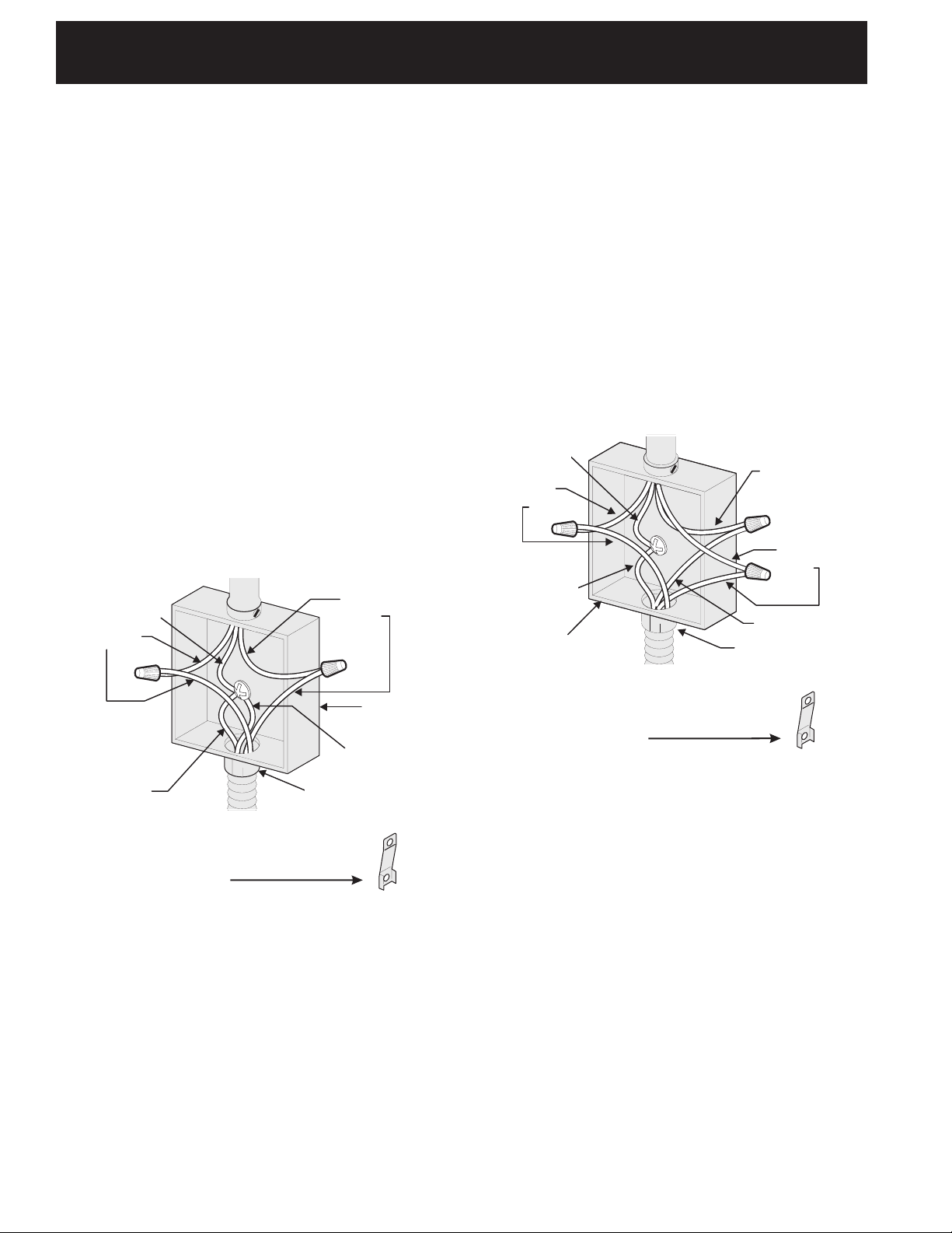
Direct Electrical Connection to the Circuit
Breaker, Fuse Box or Junction Box
If the appliance is connected directly to the circuit
breaker, fuse box or junction box, use flexible, armored
or nonmetallic sheathed copper cable (with grounding
wire). Supply a U.L. listed strain-relief at each end of
the cable. At the appliance end, the cable goes through
the Direct Connection Hole (see Figure 5) on the Cord
Mounting Plate. Wire sizes (copper wire only) and
connections must conform to the rating of the appliance.
Where local codes permit connecting the appliancegrounding conductor to the neutral (white) wire
(see Figure 5):
1. Be sure that no power is supplied on the cable from
residence.
2. Remove the grounding strap from the terminal block
and from the appliance frame.
3. In the circuit breaker, fuse box or junction box:
a) Connect the green (or bare copper) wire, the white
appliance cable wire, and the neutral (white) wire
together.
b) Connect the 2 black wires together.
c) Connect the 2 red wires together.
Cable from Residence
Neutral
(white) Wire
Red
Wires
Green
(or Bare Copper)
Wire
Cable from
Appliance
Black
Wires
Junction
Box
White Wire
U.L.-listed Conduit
Connector (or CSA
listed)
Where local codes DO NOT permit connecting the
appliance-grounding conductor to the neutral
(white) wire, or if connecting to 4-wire electrical
system (see Figure 6):
1. Be sure that no power is supplied on the cable from
residence.
2. Remove the grounding strap from the terminal block
and from the appliance frame.
3. In the circuit breaker, fuse box or junction box:
a) Connect the white appliance cable wire to the
neutral (white) wire.
b) Connect the 2 black wires together.
c) Connect the 2 red wires together.
d) Connect the green (or bare copper) grounding
wire to the grounding wire of the circuit breaker,
fuse box or junction box.
Cable from Residence
Green (or Bare
Copper) Wire
White Wire
Red
Wires
Black
Wires
Green (or Bare
Copper) Wire
White Wire
Junction
Box
Cable from
Appliance
NOTE: Be sure to remove the
supplied grounding strap.
U.L.-listed Conduit
Connector (or CSA
listed)
Figure 6 – 4-Wire Electrical System
(Example: Junction Box)
NOTE: Be sure to remove the
supplied grounding strap.
Figure 5
3-Wire (Grounded Neutral) Electrical System
(Example: Junction Box)
8

30" ELECTRIC SLIDE-IN RANGE INSTALLATION INSTRUCTIONS
¾”
(1.9 cm)
¾”
(1.9 cm)
31½”
(81 cm)
4. Cabinet Construction
To eliminate the risk of burns or
4.1
fire by reaching over heated surface units, do not
have cabinet storage space above the range. If there
is cabinet storage space above range, reduce risk by
installing a range hood that projects horizontally a
minimum of 5" (12.7 cm) beyond the bottom of the
cabinet.
4.2
Countertop Preparation
•Thecooktopsidesoftherangetoverthecutout
edge of your countertop.
•Ifyouhaveasquare finish (flat) countertop, no
countertop preparation is required. Cooktop sides lay
directly on edge of countertop.
•Formedfront-edgedcountertopsmust have molded
edge shaved flat 3/4" (1.9 cm) from each front corner
of opening (Figure 7).
•Tilecountertops may need trim cut back 3/4"(1.9
cm) from each front corner and/or rounded edge
flattened (Figure 7).
Min.
Cutout
Width
Formed or tile countertop
trimmed ¾" (1.9 cm) back at
front corners of countertop
opening.
Figure 7
•Iftheexistingcutoutwidthisgreaterthan
30 1/16" (76,4 cm), reduce the ¾" (1.9 cm)
dimension.
•Countertopmustbelevel. Place a level on the
countertop, first side to side, then front to back. If
the countertop is not level, the range will not be level.
The oven must be level for satisfactory baking results.
Cooktop sides of range fit over edges of countertop
opening
9
30" ELECTRIC SLIDE-IN RANGE INSTALLATION INSTRUCTIONS
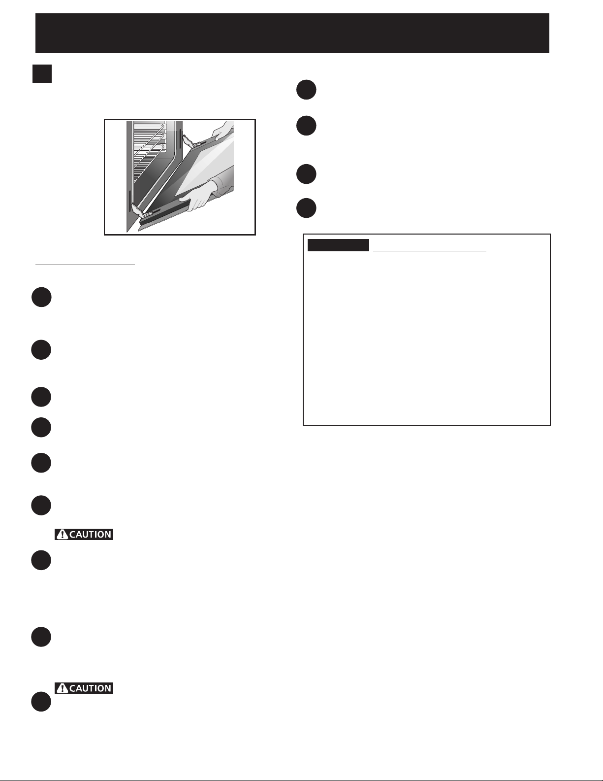
5. Range Installation
Important Note: Door removal is not a requirement for
installation of the range, but is an added convenience.
Refer to the Use and Care Guide for oven door removal
instructions.
Position range in front of the cabinet opening.
10
Make sure that the underside of the cooktop clears
the countertop. If necessary, raise the unit by lowering
11
the front leveling legs and the back leveling wheels.
Level the range (see section 6). The floor where
the range is to be installed must be level. Follow the
12
instructions under "Leveling the Range".
Slide the range into the cutout opening.
13
Figure 8
Standard Installation
The range cooktop overlaps the countertop at the
sides and the range rests on the floor. The cooktop is
1
31½" (80 cm) wide.
Install base cabinets 30" (76.2 cm) apart. Make sure
they are plumb and level before attaching cooktop.
2
Shave raised countertop edge to clear 31½" (80 cm)
wide range top rim.
Install cabinet doors 32" (81.3 cm) min. apart so as
3
not to interfere with range door opening.
Cutout countertop exactly as shown on page 1.
4
Make sure the two front leveling legs and the rear
leveling wheels (see page 11) are setup higher than
5
the height of the cabinet (shown on page 3).
Remove and discard the two rear leveling legs, they are
6
only in place to solidify the unit for the transport.
IMPORTANT
Installation With Backguard
The cutout depth of (21 3/4" (55.2 cm)Min., 22 1/8"
(56.2cm) Max.) needs to be increased to 24" (61 cm)
when installing a backguard.
Installation With End Panel
A End Panel kit can be ordered through a Service
Center.
Installation With Side Panels
A Side Panels kit can be ordered through a Service
Center. Note: Install cabinet doors 32" (81.3 cm) min.
apart so as not to interfere with range door opening.
If Accessories Needed :
In sta ll t he ant i- tip br acke t at
this point before placing the range at its final
position. Follow the installation instructions on page
7
11 or on the anti-tip bracket template supplied with
the range.
To provide an optimum installation, the top surface
of the countertop must be level and flat (lie on the
same plane) around the 3 sides that are adjacent to
8
range cooktop. Proper adjustments to make the top
flat should be made or gaps between the countertop
and the range cooktop may occur.
To reduce the risk of damaging your
appliance, do not handle or manipulate it by the
9
cooktop. Manipulate with care.
10
30" ELECTRIC SLIDE-IN RANGE INSTALLATION INSTRUCTIONS
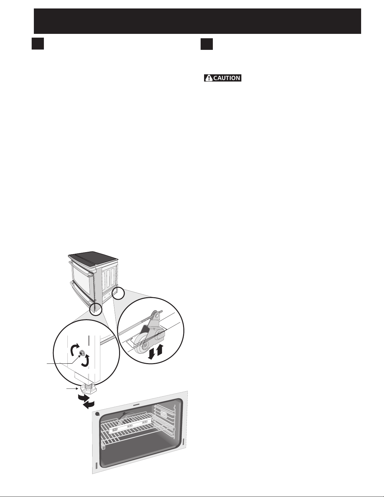
RAISE
LOWER
RAISE
RAISE
LOWER
LOWER
Font
Leveling
Leg
Leveling
Screw
Use this Screw
to Adjust Rear Leveling
Device Height
Rear Leveling
Device
6. Leveling the Range
Level the range after installation in the cutout
opening.
1. Open the range drawer. The leveling screws control
the height of the rear leg.
2. Adjust the appliance legs and wheels as follows until
the underside of the cooktop surface is sitting level
on the countertop (Figure 9).
a. To adjust the front legs, use a wrench on
the leg base and turn clockwise to lower or
counterclockwise to raise.
b. Remove the rear legs using a wrench on the leg
base and turn counterclockwise until the legs are
removed from the unit. You can discard those
legs, they are only in place to solidify the unit for
the transport.
c. To adjust the rear wheels, use a ratchet or
a nutdriver and turn the leveling screws
counterclockwise to lower or clockwise to raise.
3. Check if the range is level by installing an oven rack
in the center of the oven and placing a level on the
rack (Figure 10).
4. Take 2 readings with the level placed diagonally in
one direction and then the other. Level the range, if
necessary, by adjusting the leveling legs and wheels.
5. If the range cannot be level, contact a carpenter to
correct sagging or sloping floor.
7. Check Operation
Refer to the Use and Care Manual packaged with
the range for operating instructions and for care and
cleaning of your range.
Do not touch the elements. They may be
hot enough to cause burns.
Remove all packaging from the oven before testing.
1. Operation of Surface Elements
Turn on each of the four surface elemens and check to
see that they heat. Check the surface element indicator
light(s), if equipped.
2. Operation of Oven Elements
The oven is equipped with an electronic oven control. Each
of the functions has been factory checked before shipping.
However, it is suggested that you verify the operation of
the electronic oven controls once more. Refer to the Use
and Care Manual for operation. Follow the instructions for
the Clock, Timer, Bake, Broil, Convection (some models)
and Clean functions.
Bake–After setting the oven to 350°F (177°C) for
baking, the lower element in the oven should become
red.
Broil–When the oven is set to BROIL, the upper element
in the oven should become red.
Clean–When the oven is set for a self-cleaning cycle, the
upper element should become red during the preheat
portion of the cycle.
Figure 9
Convection (some models)–When the oven is set to
CONV. BAKE/ROAST at 350°F (177°C), both elements
cycle on and off alternately and the convection fan will
turn. The convection fan will stop turning when the oven
door is opened during convection baking or roasting.
Warmer Drawer (some models)–Set the control knob
to HI and check to see the drawer is heating.
When All Hookups are Complete
Make sure all controls are left in the OFF position.
Before You Call for Service
Read the Before you call list and operating instructions
in your Use and Care Manual . It may save you time and
expense. The list includes common occurrences that are
not the result of defective workmanship or materials in
this appliance.
Refer to the warranty and service information in your Use
and Care Manual for our phone number and address.
Please call or write if you have inquiries about your range
product and/or need to order parts.
Figure 10
11
 Loading...