

Page 1

CONTENTS
I. INSTALLATION DIAGRAM / JOINING APPLIANCES / TABLES ----------------------------------------------------------- 2
II. DATAPLATE and TECHNICAL DATA ---------------------------------------------------------------------------------------- 20
III. GENERAL INSTRUCTIONS ---------------------------------------------------------------------------------------------------- 21
IV. THE ENVIRONMENT -------------------------------------------------------------------------------------------------------------- 22
V. INSTALLATION ---------------------------------------------------------------------------------------------------------------------- 22
1. REFERENCE STANDARDS ------------------------------------------------------------------------------------------------------ 22
2. UNPACKING --------------------------------------------------------------------------------------------------------------------------- 22
3. POSITIONING ------------------------------------------------------------------------------------------------------------------------ 23
4. FUME EXHAUST AND VENTILATION ----------------------------------------------------------------------------------------- 23
5. CONNECTIONS ---------------------------------------------------------------------------------------------------------------------- 23
6. BEFORE COMPLETING INSTALLATION OPERATIONS --------------------------------------------------------------- 24
VI. USER INSTRUCTIONS -----------------------------------------------------------------------------------------------------------25
1. GRILL USE ----------------------------------------------------------------------------------------------------------------------------- 25
2. SWITCHING ON --------------------------------------------------------------------------------------------------------------------- 25
3. TRAY USE ------------------------------------------------------------------------------------------------------------------------------ 25
VII. CLEANING -------------------------------------------------------------------------------------------------------------------------- 25
1. PERIODICAL CLEANING ----------------------------------------------------------------------------------------------------------25
2. IDLE PERIODS ----------------------------------------------------------------------------------------------------------------------- 26
3. INTERNAL PARTS ------------------------------------------------------------------------------------------------------------------- 26
VIII. MAINTENANCE ------------------------------------------------------------------------------------------------------------------- 27
1. MAINTENANCE ----------------------------------------------------------------------------------------------------------------------- 27
19
Page 2
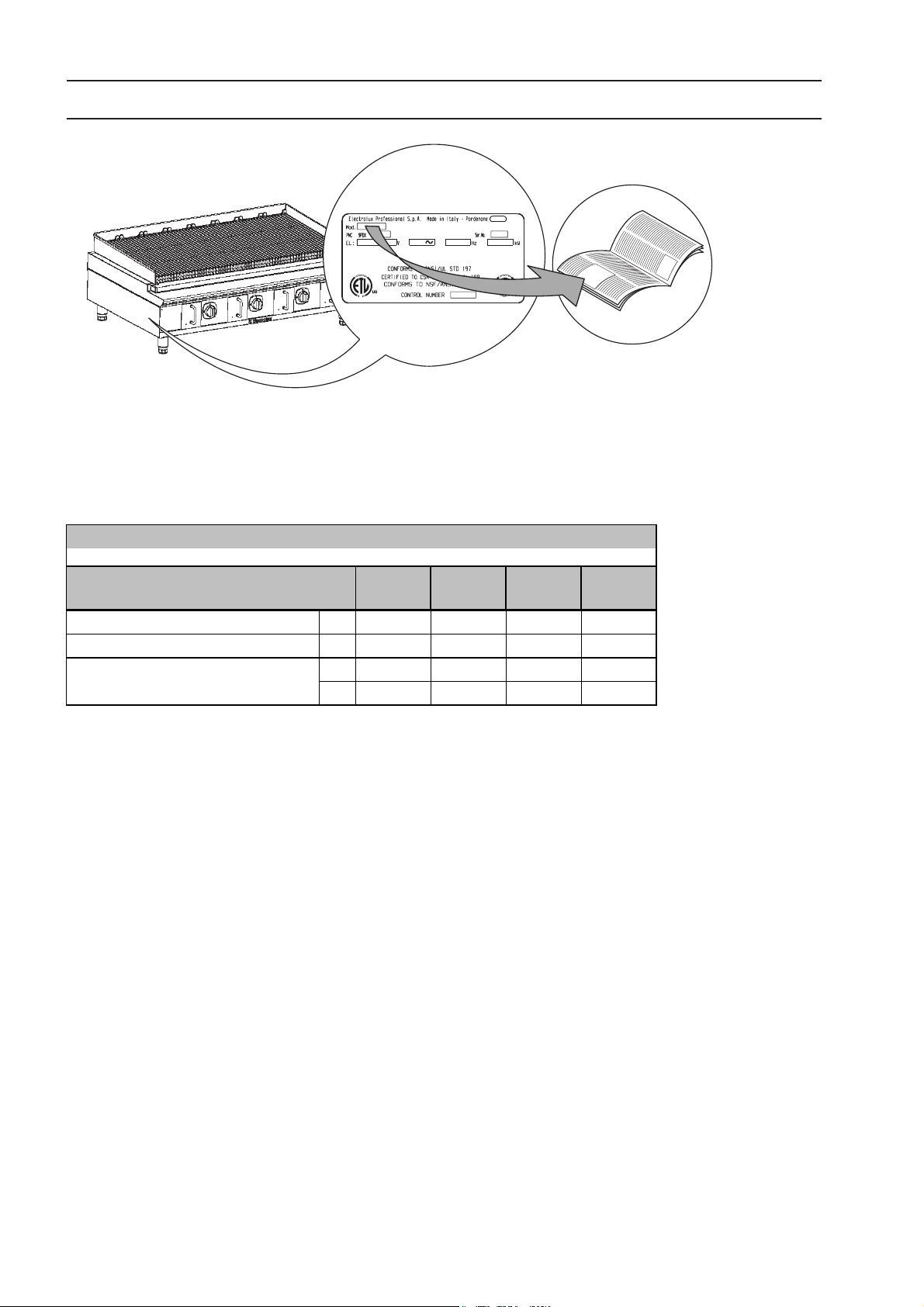
II. DATAPLATE and TECHNICAL DATA
c
IMPORTANT
This manual contains information relevant to various appliances. See the appliance dataplate located under the
control panel in order to identify the appliance (see fig. above).
TABLE A - Gas appliance technical data
MODELS
TECHNICAL DATA
Gas connection Ø 3/4” 3/4” 3/4” 3/4”
Burners Nr1234
Nominal heat output
Btu/h 33000 66000 99000 132000
169020
AGG12
305mm/12"
kW 9.65 19.3 28.9 38.6
169021
AGG2 4
610mm/24"
169022
AGG3 6
915mm/36"
169023
AGG4 8
1220mm/48"
20
Page 3
III. GENERAL INSTRUCTIONS
• Read the instruction handbook carefully before using the appliance.
• Keep the instruction handbook for future reference.
• RISK OF FIRE - Keep the area around the appliance free and clear of combustibles. Do not keep flammable
materials in the vicinity of the appliance.
• Inadequate ventilation causes asphyxia. Do not obstruct the ventilation system in the place where this
appliance is installed. Do not obstruct the vents or ducts of this or other appliances.
sos
• Installation and maintenance must only be carried out by qualified personnel authorised by the manufacturer. For assistance,
contact an authorised service centre. Demand original replacements parts.
• This appliance is designed for cooking food. It is intended for industrial use. Any use different from that indicated is improper.
• This appliance is not intended for use by people (including children) with limited physical, sensory or mental abilities or without
experience and knowledge of it, unless they are supervised or instructed in its use by a person responsible for their safety.
• Personnel using the appliance must be trained. Do not leave the appliance unattended when in use.
• Turn the appliance off in case of a fault or poor operation.
• Do not use products (even if diluted) containing chlorine (sodium hypochlorite, hydrochloric or muriatic acid, etc.) to clean the
appliance or the floor under it. Do not use metal tools to clean steel parts (wire brushes or Scotch Brite type scouring pads).
• The symbol
disposed of in order to prevent any negative consequences for the environment and the health of people.
For further information regarding the recycling of this product, contact the product agent or local dealer, the after-sales service
or the local body responsible for waste disposal.
• Place emergency telephone numbers in a visible position.
• Keep the instructions to be followed in case of smell of gas in the room in a visible position.
This information is available from the gas company.
• Do not allow oil or grease to come into contact with plastic parts.
• Do not allow dirt, fat, food or other residuals to form deposits on the appliance.
• Do not clean the appliance with direct jets of water.
L given on the product indicates that it should not be treated as domestic waste, but must be correctly
• Attention:
• Do not use or store petrol or other flammable liquids, gases or materials in the vicinity of this or other appliances
• Do not use sprays near this appliance while it is operating.
• This appliance is not suitable for marine environments
Failure to observe the above can compromise the safety of the appliance. Failure to
observe the above invalidates the warranty.
21
Page 4

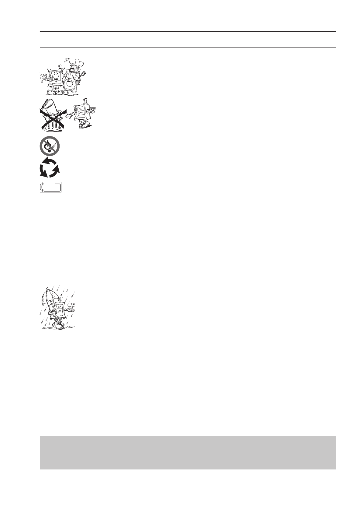
IV. THE ENVIRONMENT
V. INSTALLATION
1. PACKING
The packing materials are environmentally
friendly and can be stored without risk or burned
in an appropriate waste incineration plant.
Recyclable plastic parts are marked with:
Polyethylene: outer wrapping, instruction booklet bag,
PE
Polypropylene: roof packing panels, straps.
PP
Polystyrene foam: corner protectors.
PS
gas nozzle bag.
2. USE
Our appliances offer high performance and efficiency. To reduce
electricity, water or gas consumption, do not use the appliance
empty or in conditions that compromise its optimum efficiency;
the appliance must be used in a well-ventilated place, to avoid
the creation of dangerous mixtures of unburnt gases in the room.
When possible, preheat only before use.
3. CLEANING
In order to reduce the emission of pollutants into the
environment, clean the appliance (externally and when
necessary internally) with products that are more than 90%
biodegradable (for further information refer to section VII
“CLEANING”).
4. DISPOSAL
Do not disperse in the environment. Our
appliances are manufactured using more than
90% (in weight) recyclable metals (stainless
steel, iron, aluminium, galvanised sheet,
copper, etc.).
Make the appliance unusable by removing
cavity closing devices (when present) in order to avoid the risk
of someone becoming trapped inside.
the power cable and any compartment or
• Carefully read the installation and
maintenance procedures given in this instruction
manual before installing the appliance.
• Installation, maintenance and conversion to another type
of gas must only be carried out by qualified personnel
authorised by the manufacturer.
• Failure to observe the correct installation, conversion and
modification procedures can result in damage to the
appliance, danger for people, and invalidates the
Manufacturer’s warranty.
1. REFERENCE STANDARDS
• This appliance must comply with the applicable federal,
state or local regulations.
These installation procedures must be carried out by
qualified personnel, otherwise the warranty will be
invalidated.
The NFPA (National Fire Protection Association) Inc states,
in its latest 96 edition, that the local regulations are the
“competent authority” regarding the installation requirements
for appliances. Therefore, all connections (gas, electrical,
water, discharges, etc.) must comply with all the local
regulations.
• In the lack of local regulations, installation must be carried out in compliance with the “National Fuel Gas Code”,
ANSI Z223.1/NFPA 54, or the “Natural Gas and Propane
Installation Code”, CSAB 149.1, in particular:
1) the appliance must be disconnected from the gas
supply during any operation on the system pressure exceeding 1/2 psi (35 mbar/3.5 kPa).
2) the appliance must be isolated from the gas supply
during any operation on the system pressure below or
equal to 1/2psi (35 mbar/3.5 kPa).
2. UNPACKING
ATTENTION!
Immediately check for any damage caused during
transport.
• The forwarder is responsible for the safety of the goods
during transport and delivery.
• Inspect the packing before and after unloading.
• Make a complaint to the forwarder in case of visible or
hidden damage, reporting any damage or shortages on
the dispatch note upon delivery.
• The driver must sign the dispatch note: the
forwarder can reject the claim if the dispatch note
is not signed (the forwarder can provide the
necessary form).
• Unpack, taking care not to damage the appliance. Wear
protective gloves.
• Carefully remove the protective film from metal surfaces
and clean any traces of glue with a suitable solvent.
• For hidden damage or shortages becoming apparent
only after unpacking, request the forwarder for inspection
of the goods within and not later than 15 days of delivery.
• Keep all the documentation contained in the packing.
22
Page 5

3. POSITIONING
• Handle the appliance with care in order to avoid damage
or danger to people. Use a pallet for handling and
positioning.
• The installation diagram provided in this instruction
manual gives the appliance dimensions and the position
of connections. Check that they are available and ready
for making all the necessary connections.
• The appliance can be installed separately or combined
with other appliances of the same range.
• The appliances are not designed for built-in installation;
ensure a distance of at least 8"/203.2 mm from the rear
wall, to allow connection and aeration of the burners; in
case of any combustible side walls, leave at least 6"/
152.4 mm, otherwise (non-combustible walls) they can
be brought near (0"/0 mm).
• Suitably insulate any surfaces that are at distances less
than those indicated in the installation diagram.
• Do not store or use flammable materials and liquids near
the appliance.
• Check and if necessary level the appliance after
positioning. Incorrect levelling can cause appliance
malfunctioning.
3.1. JOINING APPLIANCES (Fig. 1A- 1B-1C-1D-1E-1F)
• Remove knobs “M” and control panels “C” of the appliances,
removing the 4 fixing screws “V” (Fig. 1A).
• Remove the precut “PT” (FIG.1B) from each side to be
joined.
• Bring the appliances together and level them by turning
the feet until the tops match (FIG.1C).
• From inside the control panel of the appliances, join them
at the front part, tightening one M5x40 hex head screw
on the nut (supplied) (FIG.1D).
• Remove the screws “V” (FIG.1E).
• Position the plate “P” to match the holes and fix it using
the screws supplied (FIG.1F).
• Refit the control panels and knobs.
• Use NSF silicone to seal the gaps between joined
appliances and tops on refrigerated or compartment base.
4. FUME EXHAUST AND VENTILATION
• Only install the appliance in a wellventilated place.
• Do not obstruct the ventilation system
in any way.
• Do not obstruct the vent and discharge
holes of this appliance or others present
in the room.
ATTENTION! Inadequate ventilation
causes appliance malfunction and
creates the risk of asphyxia and danger
to people.
5. CONNECTIONS
• Any installation work or maintenance to the
supply system must only be carried out by the utility
company or an authorised installer.
• Refer to the appliance dataplate for the product code.
• See the installation diagram for the type and position of
appliance connections.
5.1. GAS APPLIANCES
IMPORTANT! This appliance is arranged and tested to ope-
rate on Natural gas (G20, 7mbar/3"wc); to convert it to
another type of gas, follow the instructions in par. 5.1.6.
of this section.
5.1.1. BEFORE CONNECTING
• Make sure the appliance is arranged for the type of gas
to be used. Otherwise, follow the instructions given in
the section: “Gas appliance conversion / adjustment”.
• Fit a rapid gas shut-off cock/valve ahead of each
appliance. Install the cock/valve in an easily accessed
place.
• Clean the pipes to remove any dust, dirt or foreign matter
which could block the supply.
• The gas supply line must ensure the gas flow necessary
for full operation of all the appliances connected to the
system. A supply line with insufficient flow will affect
correct operation of the appliances connected to it.
5.1.2. CONNECTION
• See the installation diagram for the position of the gas
connection on the bottom of the appliance.
• Remove the plastic protection cover (if present) from the
appliance gas union before connecting.
• After installation, use soapy water to check connections
for leaks.
5.1.3. SUPPLY PRESSURE CHECK
Make sure the appliance is suitable for the type of gas
available, according to that specified on the dataplate
(otherwise, follow the instructions in par. “Conversion to
another type of gas”). The supply pressure must be
measured with the appliance operating, using a
manometer (min. 0.1 mbar).
• Remove the control panel.
• Remove screw “N” from the pressure point and connect
the pressure gauge “O” (fig. 2A).
• Compare the value read on the manometer with that given
in Table B (see handbook Appendix)
• If the manometer gives a pressure outside the range of
values in Table B, do not use the appliance. Consult the
gas company.
23
Page 6

5.1.4 GAS PRESSURE REGULATOR
3
1
2
• A gas pressure regulator (supplied in a plastic bag with
the appliance) must be installed in an easily accessed
position ahead of the appliance.
The pressure regulator should preferably be fitted
horizontally, to ensure the right outlet pressure:
•“1” connection side gas from mains.
•“2” pressure regulator (3.3"x2.9"x2.7" / 85x75x71mm);
•“3” connection side gas towards the appliance;
The arrow on the regulator (
flow direction.
NOTE! These models are designed and certified for use
with natural or propane gas. For natural gas, the pressure
regulator on the manifold is set to 7mbar.
5.1.5. PRIMARY AIR CHECK
When the primary air supply is correctly adjusted, the flame
does not “float” with burner cold and there is no flareback
with burner hot.
• Undo screw “A” and position aerator “E” at distance “H”
given in table B; retighten screw “A” and seal with paint
(fig. 3A).
) indicates the gas
5.1.6.2 MINIMUM FLAME SCREW REPLACEMENT (fig. 2A)
• Unscrew minimum flame screw “M” from the cock and
replace it with one suitable for the type of gas (screw
down fully) (Table B, see appendix).
6. BEFORE COMPLETING THE INSTALLATION
OPERATIONS
Use soapy water to check all gas connections for leaks. DO
NOT use a naked flame to check for gas leaks. Light all the
burners individually and also together, to check correct
operation of the gas valves, rings and lighting. For each
burner, adjust the flame regulator to the lowest setting,
individually and together; after completing the operations,
the installer must instruct the user on the correct method
of use. If the appliance does not work properly after
carrying out all the checks, contact the local after-sales
service centre.
5.1.6. CONVERSION TO ANOTHER TYPE OF GAS
Table B “Technical data/gas nozzles” gives the types of
nozzles (contained in a bag supplied with the appliance,
together with the pressure regulator) to be used when
replacing those fitted by the manufacturer; the number is
stamped on the nozzle body.
At the end of the procedure, carry out the following check-
list:
Check Ok
• burner nozzle/s change
• correct adjustment of pr im ary air at burner/s
• pilot nozzle/s change
• m inimum flame s crew/s change
• correct adjustment of pi lot/s , if necessary
• correct adjustment of supply pressure (see
techni cal data/gas noz zl es tabl e)
• apply the sticker (supplied) with data of new gas
type used
5.1.6.1 BURNER NOZZLE REPLACEMENT (fig. 3A)
• Loosen screw “A” and move bushing “E” to unscrew and
replace nozzle “C” with one suitable for the type of gas to
be used, according to that given in Table B.
• The nozzle diameter is given in hundredths of mm on the
nozzle body.
• Tighten down nozzle “C”.
• Refit bushing “E” according to distance H (Table B), and
tighten down screw “A”
24
Page 7

VI OPERATING INSTRUCTIONS
1. GRILL USE
• The appliance is intended for industrial use by trained
personnel.
• Do not use the appliance empty for long periods or in
conditions that compromise its optimum efficiency. Also,
if possible, preheat the appliance immediately before
use.
• The grill is designed for direct cooking of food on the hotplate (hamburgers, chops, eggs, sausages, fish, vegetables,
etc.). Any other use is deemed improper.
• Empty the oil collection container every day before use
(if necessary, empty it several times a day).
• Do not use the grill to heat pots or pans.
• Grill 305mm/12": it consists of a single cooking zone
controlled by a gas valve.
• Grill 610mm/24": it consists of two cooking zones (left
and right side) controlled by two gas valves, one for each
zone.
• Grill 915mm/36": it consists of three cooking zones (left,
middle and right side) controlled by three gas valves,
one for each zone.
• Grill 1220mm/48": it consists of four cooking zones (from
left to right) controlled by four gas valves, one for each
zone.
3. TRAY USE
• For better cooking results and to facilitate cleaning at the
end of the day, it is advisable to pour a little water into
each grease collection tray.
ATTENTION: The tray can become very hot, therefore handle
it using suitable protection to avoid burns.
VII. CLEANING
2. SWITCHING ON/OFF
The gas control knob “A” of each burner has 3 positions:
V “Off”
C “On”
A “Max. flame”
B “Min. flame”
Lighting
• Remove the front tray “C” to access the pilot.
• Press down and turn knob “A” to “C”; at the same time,
hold a flame to the pilot from outside. The flame must
remain alight when knob “A” is released; otherwise, repeat
the operation.
Lighting the main burner
• Turn knob “A” from “C” to "A".
• For minimum, turn knob “A” to "B".
A
C
Switching off
• Press and turn knob “A” to "V".
• At the end of the day, close the gas cock located ahead of
the appliance.
1. EXTERNAL PARTS
SATIN-FINISH STEEL SURFACES (daily)
• Clean all steel surfaces: dirt is easily removed when it
has just formed.
• Remove grime, fat and other cooking residuals from steel
surfaces when cool using soapy water, with or without
detergent, and a cloth or sponge. Dry the surfaces thoroughly
after cleaning.
• In case of encrusted grime, fat or food residuals, go over
with a cloth or sponge, wiping in the direction of the satin
finish and rinsing often: rubbing in a circular motion
combined with the particles of dirt on the cloth/sponge
could spoil the steel’s satin finish.
• Metal objects can spoil or damage the steel: damaged
surfaces become dirty more easily and are more subject
to corrosion.
• Restore the satin finish if necessary.
SURFACES BLACKENED BY HEAT (when necessary)
Exposure to high temperatures can cause the formation of dark
marks. These do not constitute damage and can be removed
by following the instructions given in the previous section.
OTHER SURFACES
SURFACES IN SOFT IRON OR CAST IRON (daily)
Remove grime using a damp cloth or, in case of
encrustations, the accessories (optional or supplied)
specified in the list. After cleaning, switch the appliance
on to dry the surface quickly, then lightly lubricate the
surface with cooking oil.
25
Page 8
COLLECTION TRAYS AND TANKS (even several times a day)
R
S
Remove grease, oil, food residuals, etc. from tanks, trays and
containers in general used for collection. Always clean these
containers at the end of the day. While using the appliance,
empty them when they are nearly full.
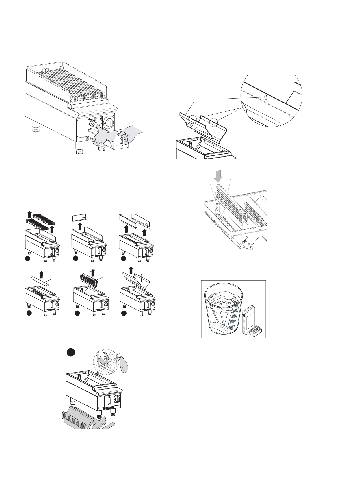
• Using a scraper or similar tool, clean the combustion
chamber ribs that run the juices into the collection tray,
then go over with a damp cloth. During this operation
take care not to damage the pilot flame igniter assembly.
• After carrying out cleaning operations make sure the burner
and combustion chamber are perfectly clean and dry, then
carefully refit the previously removed parts, ensuring that:
- holes “G” of panels “F” are at the top;
1.1 CLEANING THE BURNER AND COMBUSTION
CHAMBER
• (figure 1) Remove cooking grills “A” by simply lifting them.
• (figure 2) Lift splash guard “B” to release it from the tabs
of splash guards “C”, then move it forward to remove.
• (figure 3) Lift splash guards “C” to remove them.
• (figure 4) Remove protection cover “D” by lifting it.
• (figure 5) Remove radiant panel “E”, lifting it out of it seat.
• (figure 6) Remove panels “E” by lifting them.
A
1
D
2
B
C
C
3
E
F
F
G
- radiators “R” are resting on their supports “S”.
1.2 SPLASH GUARDS, PANELS, PROTECTION COVERS
Remove the splash guards, panels and protection covers from
the appliance, as described in the previous section, and place
them in a bowl full of hot soapy water, with or without detergent.
4
5
6
• (figure 7) Clean the burner around the flame zone and
along the slots of the flame protector, removing all traces
of dust and deposits, taking care not to enlarge the flame
holes.
7
r
degrease
sgrassante
1.3 GRILLS
• ROUTINE CLEANING (after every use)
Remove food residuals with a damp cloth and neutral
surfactants; if necessary, remove charred deposits using
brush with NON-metallic bristles.
After cleaning,
switch the appliance on to dry the surface quickly, then
lightly lubricate the surface with cooking oil.
26
Page 9

• PERIODICITY (every two months or more often in case of
prolonged use of the appliance)
Lubricate the entire surface with cooking oil, then switch
the appliance on at minimum until all the oil is evaporated/
absorbed.
• OXIDISED AREAS (when necessary)
Eliminate any oxidised areas with abrasive paper (glass
abrasive, NEVER metallic) and immediately repeat the
“periodicity” treatment.
2. IDLE PERIODS
If the appliance is not going to be used for some time, take
the following precautions:
• Close cocks or main switches ahead of the appliance.
• Go over all stainless-steel surfaces vigorously with a cloth
moistened with paraffin oil in order to create a protective film.
• Air the premises periodically.
• Have the appliance checked before using it again.
3. INTERNAL PARTS (every 6 months)
IMPORTANT! Operations to be carried out only by
specialised technicians.
• Check the condition of internal parts.
• Remove any deposits of dirt inside the appliance.
• Check and clean the discharge system.
• Remove the 4 fixing screws “V” of back “S” to access the
inner rear part of the appliance.
VIII MAINTENANCE
1. MAINTENANCE
All parts requiring maintenance are accessible from the front
of the appliance, after removing the control panel.
1.1 BRIEF TROUBLESHOOTING GUIDE
Even with normal use, malfunctions can occur.
The pilot burner does not light
Possible causes:
• Insufficient pressure in gas pipes.
• Faulty gas valve.
The pilot burner goes out when the igniter knob is released
Possible causes:
• The pilot burner is not heating the thermocouple
sufficiently.
• Faulty thermocouple.
• The gas valve knob is not being pressed enough.
• Lack of gas pressure at the valve.
• Faulty gas valve.
The pilot burner is still lit but the main burner does not light
Possible causes:
• Loss of pressure in gas pipe.
• Blocked nozzle or faulty gas valve.
• Burner with gas outlet holes clogged.
V
NOTE ! In particular conditions (e.g. intensive appliance
use, salty environment, etc.) the above cleaning should
be more frequent.
S
INSTRUCTIONS FOR REPLACING PARTS
(to be carried out only by a specialised installer)
VALV E
• Remove the knobs and control panel.
• Unscrew the pilot and thermocouple pipe.
• Unscrew the gas inlet and outlet connections.
• For installation carry out the same procedure in reverse
order.
THERMOCOUPLE, PILOT BURNER ASSEMBLY
• Remove the knobs and control panel.
• Unscrew the pilot and thermocouple pipe and remove it.
• Replace the part.
GRILL MAIN BURNER
• Remove the knobs and control panel.
• Remove the clamp fixing the burner to the gas pipe and
nozzle holder.
• Remove the burner and replace it.
For installation carry out the same procedure in reverse
order.
1.2 MAINTENANCE SCHEDULE
• It is advisable to have the appliance inspected by an
authorised person at least every 12 months. For this
purpose, it is advisable to stipulate a servicing contract.
27
 Loading...