7.3 Special cleaning instructions ................................. 54
- CONTROL PANEL FIGURES .......................................... 295
- APPLIANCE IDENTIFICATION
5938 034 00
Identification dataplate
Made in E E C.
PNC 9PDX 260462 05
IP25
260462
31
GB
I. MAIN FEATURES
1. DESCRIPTION OF APPLIANCE
This booklet describes a number of appliance models.
For more detailed information about the model in your possession,
refer to "Technical Data" table 1.
The appliance has the following features:
• Digital temperature indicator.
• Thermostatic probe for measuring the core temperature of products (core temperature probe).
• Continuous monitoring of cooking parameters throughout the
entire cooking cycle.
• Periodic draining and automatic washing of the boiler to prevent
the build-up of lime-scale (only available on certain models).
• Boiler lime-scale level indicator (see corresponding paragraph)(only
available on certain models).
• Oven chamber automatic fast steam drain device for gratins.
• Air-break anti-backup drain device to prevent backflows from the
drainage system from entering the oven (only available on certain
models).
• Oven chamber lighting.
• Double-action door opening safety mechanism designed to
protect the user from scalding steam (only available on certain
models).
• Double-glazed oven door for reduced heat dispersion into the
kitchen and low temperatures on the exterior of the oven.
• Daily oven chamber cleaning cycle (CLEANING SYSTEM) (only
available on certain models).
• Self-diagnostics system indicating oven faults using error codes
(see "Information and error codes ").
For UK and COMMONWEALTH only:
This appliance is designated as a forced draught burner, therefore the appliance is classed as COMCAT5 and only installers
who held the relevant gas qualification are allowed to install/commission and service this product.
WARNING:
Failure to use a qualified/authorised installer WILL INVALIDATE THE WARRANTY conditions and may render the appliance
inoperative.
If any doubt please consult the manufacturer for further advice.
Under no circumstances must this product be used unless installed and /or commissioned by a qualified engineer.
Noise emission data: Noise emissions generated by the appli-
ances described in this booklet do not exceed 70 dB (A).
Your appliance model is indicated in the box marked PNC on
*
the Identification dataplate affixed to the bottom left hand side of the
oven.
Gas consumption was calculated in the following conditions:
**
- Temperature 15°C;
- Atmospheric pressure 1013.25 mbar;
- Net calorific value :
G30 (Hi=45.65 MJoule/kg)
G31 LPG (Hi=46.34 MJoule/kg)
G20 natural gas (Hi=34.02 MJoule/m3)
G25 natural gas (Hi=29.25 MJoule/m3)
LPG (Japan) (Hi=46.34 MJoule/kg)
13A natural gas (Japan) (Hi=34.02 MJoule/m3)
• Before installing or using the appliance read this instruction
booklet carefully because it contains important information
concerning safety, operation and maintenance.
• Keep this instruction booklet in a safe place for future
consultation by other users or purchasers in the event that the
appliance is resold.
Important: Installation and maintenance of the appliance
and its conversion to a different gas supply must only be
performed by a qualified installer authorised by the
manufacturer.
• This appliance is intended for collective use and is expressly
designed for cooking food. Any other use is deemed improper.
The appliance must only be used by trained staff.
• This appliance is not intended for use by people (including
children) with limited physical, sensory or mental abilities or
without experience and knowledge of it, unless they are supervised
or instructed in its use by a person responsible for their safety.
• Switch off the appliance if it breaks down or malfunctions.
• Only contact the technical service centre authorised by the
manufacturer for repairs and only use original spare parts.
Failure to comply with the above requirement may jeopardise
the safety of the appliance and invalidate the guarantee.
• Do not wash the appliance with water jets.
• Do not use products containing chlorine (bleach, hydrochloric
acid etc.) even diluted, to clean steel surfaces.
• Do not use corrosive substances (e.g. muriatic acid) to clean the
floor under the appliance.
• For more information, refer to the section on "Care and
maintenance".
4. SAFEGUARDING THE ENVIRONMENT
4.1 PACKAGING
• All the packaging materials used are environmentally friendly.
They may be stored at no risk or burnt at an authorised incineration
plant. Plastic materials suitable for recycling are marked with the
following symbols:
expanded polystyrene: protective surround elements
PS
4.2 USE
• The appliance has been designed and perfected under laboratory
testing conditions to offer exceptional levels of performance.
However, to minimise energy consumption (electricity, gas and
water), do not leave the appliance in operation for long periods
without food in the oven chamber and avoid conditions that
reduce efficiency (e.g. door open). We also recommend
preheating the appliance immediately prior to use.
4.3 CLEANING
• To minimise the emission of pollutants into the environment,
clean the appliance (externally and, where necessary, internally)
with products that are at least 90% biodegradable.
4.4 DISPOSAL
• The appliance must be disposed of properly at the end of its
service life.
• The appliance is made from more than 90% recyclable materials
(stainless steel, iron, aluminium, galvanised sheet steel, etc.).
These materials may therefore be scrapped in accordance with
local waste disposal regulations at a conventional recycling
plant.
• Make the appliance unusable by cutting off the power cord. Also
remove any compartment or interior closure device fitted on the
appliance to prevent persons from becoming trapped inside.
The symbol L on the product indicates that this product
should not be treated as domestic waste, but must be correctly
disposed of in order to prevent possible negative consequences
for the environment and the human health.
Regarding the recycling of this product, please contact the sales
agent or dealer of your product, your after-sales service or the
appropriate waste disposal service.
34
5938 034 00
II. INSTRUCTIONS FOR INSTALLATION
GB
Important: The oven outer panels must be removed to
perform the operations described in this chapter. Since the
appliance must be switched on to make certain
adjustments, exercise the utmost care when working in the
vicinity of live electrical parts.
1. PLACE OF INSTALLATION
• The appliance must only be installed in adequately ventilated
premises.
1.1 REFERENCE STANDARDS
• Install the appliance according to the prescriptions of current
safety standards.
2. POSITIONING
• Unpack the appliance and carefully remove the protective film
from the outer panels to avoid leaving any trace of adhesive. Use
a suitable solvent to remove any adhesive residues.
• Dispose of the packaging as instructed in the chapter on
"Safeguarding the environment"
• Refer to the installation diagrams at the beginning of this
booklet for the space requirements and connection dimensions
of the appliance.
• Clearance of approximately 50 cm must be left between the
appliance’s left side panel and adjacent structures in order to
provide space for maintenance operations when needed; the
right side panel and the rear panel of the appliance must be at
least 10 cm from adjacent structures.
• Place the appliance in the required position and adjust the
height of the work surface using the adjustable feet.
• The appliance is not suitable for built-in installation.
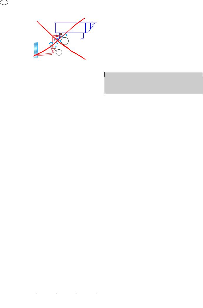
In the case of discharge direction to the outside or into a central
flue (Fig. "1c"), the discharge ducts must NOT present an overall
length in excess of 3 metres, must NOT have any reductions in
diameter, and must be subjected to periodic inspection and,
when necessary, cleaning.
Warning: Since combusted gas (see figure) can reach very
high temperatures, check the heat resistant properties of
extension ducts if fitted and the filters in the extractor hood
to ensure the materials are compatible with the temperature
conditions. In addition, periodically check the condition of
the filters which, if excessively fouled with fat and dirt, will
reduce the efficiency of the suction system and may catch
fire.
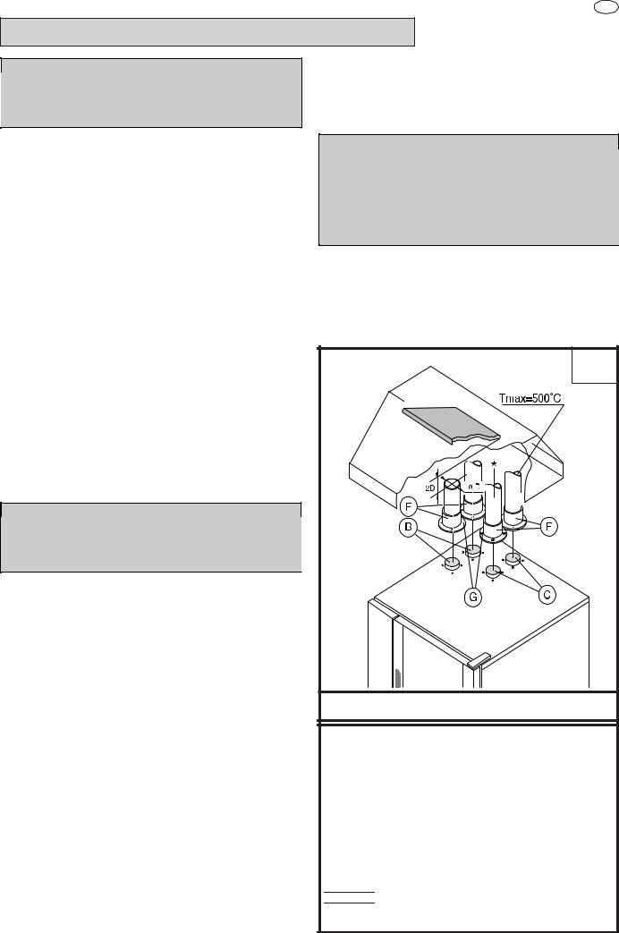
3.3 INSTALLATION OF ACCESSORIES
Accessories can be easily installed by following the figures below
together with the relative key.
The screw holes for fixing accessories "A" and "F" are 3.5 mm in
diameter and they must be drilled in-situ on the oven cover
incorrespondence with the punch marks.
CONSTRUCTION TYPE
A3
1a
Important:
Make sure steam from the oven’s drain or adjacent
appliances does not enter the aeration vents under the
appliance, designed to cool internal components
located at the bottom of the appliance.
3. COMBUSTED GAS DISCHARGE
3.1 FOREWORD
In relation to the combustion technology utilised, gas fired steam/
convection ovens are classified in accordance with their
"Construction Type". For each of these types of appliances
applicable regulations stipulate a specific type of combusted gas
discharge system.
Consequently, before installing the discharge system:
a) identify the "Construction type" of your model in Table 1
(technical data) or by checking the appliance identification
dataplate;
b) choose the diagram with the type of construction among
those shown below, depending on how you intend to exhaust the
appliance fumes from the place of installation (e.g. discharge
under extraction hood, direct to the outside, or in a central flue).
3.2 WARNINGS REGARDING THE FLUING SYSTEM
Before installation check, on the basis of the contents of the
reference standard, to ensure that the volume aspirated by the
fumes exhausting system is greater than the volume of combusted
gas produced by the appliance (see point 1.1).
If the solution of combusted gas discharge under an extractor hood
is chosen, observe the distance (shown in the figure) between the
top of the discharge pipe and the lowest point of the hood filters. This
5938 034 00
distance is defined on the basis of discharge pipe diameter "D".
DIRECT UNDUCTED DISCHARGE UNDER EXTRACTOR HOOD
LEGENDA:
A:Cam / draught damper accessory
(to be ordered from manufacturer)
B:Boiler combusted gas discharge
C:Oven chamber convector combusted gas discharge
E:Adapter ring for commercial ducts
(to be ordered from manufacturer)
F:Conical connections for single outlet (supplied)
• The appliance must be permanently connected to the mains
power supply with an H05 RN-F type cable. The power supply
cable must be protected by a metal or rigid plastic conduit. If the
If the appliance is connected by way of an existing lead, do not
insert the cable conduit into the appliance and make particularly
sure that the conduit has no sharp edges.
• The appliance must be suitably earthed. The earthing conductor
must therefore be connected to the terminal marked G on the
connection terminal board. The appliance must also be connected
to an earth bonding system.
This connection is made using the stop screw marked E located
on the outside of the appliance near the power cable inlet.
The bonding wire must have a minimum cross-section of 10 mm
4.1 INSTALLING THE POWER SUPPLY CABLE
To access the power supply cable connection terminal board,
proceed as follows:
2
.
*
Tmax=350°C
3 meters MAX
E
B
C
SILICONE
DISCHARGE TO THE OUTSIDE OR CENTRAL FLUE WITH SHROUD
A
4. ELECTRICAL CONNECTION
The appliance must be connected to the mains power supply
in compliance with current regulations.
• Before connecting the appliance to the mains supply, make sure
that the voltage and frequency shown on the appliance identification
dataplate correspond with those of the power supply.
G
Model 6 - 10 - 20 GN
• Remove the left side panel.
• Connect the power supply cable to the terminal board according
to the instructions given in the wiring diagram and fasten the
power supply cable by means of the cable clamp.
The manufacturer declines all responsibility if the applicable
safety regulations are disregarded.
5. WATER MAINS CONNECTION
(Refer to the installation diagrams at the beginning of this booklet).
When connecting the appliance to the water system with
flexible tubes they must be new and not used.
The appliance is fitted with two separate water inlets ("B" and "N").
The water lines supplying both inlets must be fitted with a
mechanical filter and shut-off cock.
Before fitting the filters allow the water to flow out for sufficient time
to flush any solid particles from the piping.
Pressure between 150 and 450 kPa (1.5-4.5 bar).
WATER INLET “N”
Attention (water inlet N)
If the supply pipes provided with the appliance are not long
enough for installation, use longer ones with int. diameter at
least ø 20 mm and free of elbow unions.
Note:
To check correct water installation, make sure the rotating wash
arm (CLEANING SYSTEM) does not turn below 100 rpm (120
max).
5938 034 00
36
GB
5.1 WATER SUPPLY CHARACTERISTICS
The appliance must be supplied with drinking water having
specific characteristics given in this section.
HARDNESS FILTER
Water
in le t
B
N
^ OPERATING LEVEL (C = Convect, Convection).
The hardness values given in the table are for reducing scaling
inside the steam generator and possible cooking compartment
washing system.
If the available water does not have these hardness characteristics
a water softener must be installed.
Therefore the Automatic Water Softener with automatic
regeneration for installing on the inlet line, can be requested as
an accessory; it has a Resin Sterilizer kit (also by request).
HARDNESS AND CHLORIDE FILTERS
The chloride concentration (Cl-) (ppm - mg/l) values with pH
(>7) and Conductivity (µS/cm) (measured at 20°C) must be
such as to not damage the steel structures inside the oven (only
water inlet B).
Therefore the characteristics of the available water must be
identified in the graph given at the end of this handbook (page
299), if necessary installing at the inlet the type of filter indicated
in the relevant area of the values.
The filters indicated are:
- No filter for chloride (Cl-) in the conforming area (Normal)
- Nanofilter
as an accessory on request, called Water Filter.
- Osmotizer.
Make sure the water coming out the filter is inside the optimum
area (Normal).
These filters also have the function of reducing the water
hardness to optimum values (below 5°f), and therefore also act
as a water softener.
ATTENTION: Periodical checking according to the filter
manufacturer’s instructions is important to maintain its efficiency
and avoid the risk of corrosion in the appliance.
Level C ovens are convection ovens. If water having
characteristics outside those specified is used to create humidity
inside the oven, there will be the risk corrosion of the compartment
and that present inside it.
Carry out regular maintenance of the water softeners and filters
to ensure their optimum efficiency.
To avoid damage to the appliance, after every periodical
regeneration do a filter cleaning cycle without introducing water
in the oven.
The manufacturer declines any liability in case of incorrect
maintenance.
Important:
The use of dosing systems designed to prevent the buildup of lime-scale in pipes (i.e. polyphosphate dosing
systems) is prohibited since such systems may impair the
performance of the appliance.
Appl.Hardness
°fppm°dH
A ^0,5 - 55 - 500,28 - 2,8
B ^0,5 - 55 - 500,28 - 2,8
C ^m ax 5m ax 50m ax 2,8
A ^m ax 5m ax 50m ax 2,8
B ^m ax 40m ax 400m ax 22
C ^m ax 5m ax 50m ax 2,8
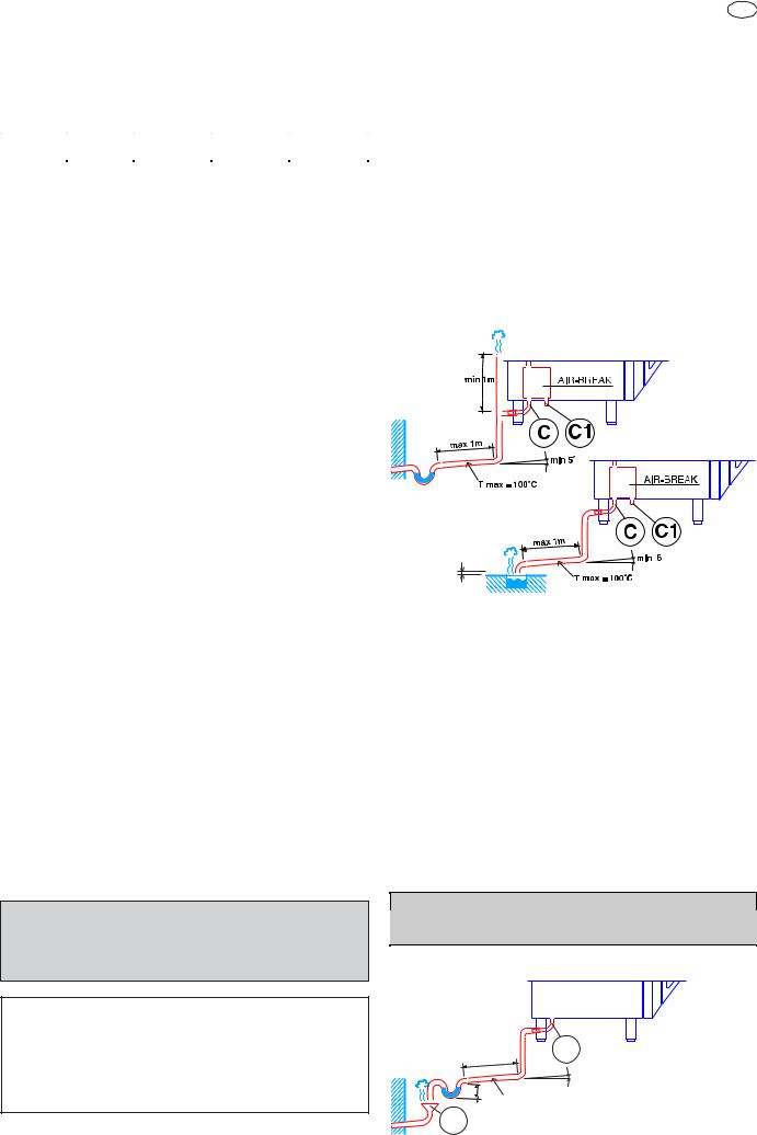
5.2 WATER DRAIN SYSTEM
- OVEN level A -
The oven is supplied with an air-break system to prevent any
backflow from the drainage system from reaching the oven’s
internal circuits and the cooking chamber. The presence of this
system means that the drain pipe can be connected directly to
the mains drainage system or routed to a floor gulley with grating.
The flexible drainage hose or rigid pipe can be directed to the
side or rear of the appliance if the oven is not positioned against
a wall; this line must not be directed towards the front of the
appliance to prevent interference with roll-in grid racks. The
drainage pipe internal diameter must be no smaller than the
oven drain outlet (1” 1/4), no longer than 1 metre and must
resist temperatures of up to at least 100°C. Avoid restrictions in
the case of flexible hose pipes, do not fit elbows on metal pipes
anywhere along the drainage line. Also avoid horizontal sections
in which water might collect (minimum gradient 5%).
C - Oven drain
C1 - Safety outlet
min 0,04m
Important:
- Do not obstruct the safety outlet C1.
- Do not connect the safety outlet C1 to the drainage system.
Note:
If water comes out of the AIR-BREAK (safety outlet C1) this means
the drain C is blocked. Any elimination of the obstruction must
be carried out by specialised technical personnel.
- OVEN level B and C -
Connect drain fitting “C” to a drain pipe of the same diameter which
is between 0.5 and 3 metres in length and is resistant to
temperatures of at least 100°C. The drain pipe must be siphoned
(height 80 mm) to an open drain “O” (“Air-Break”) or floor grating
(see Fig. 12b) in order to prevent any back-flow from the sewage
system from reaching the piping inside the oven or oven chamber.
Check the hoses and elbows on metal pipes for kinks or pinching
along the entire drain line and make sure the drain line has a
minimum gradient of 5° to prevent water from collecting inside the
system.
Important: The drain system must be installed so that any
vapours from the open drain do not enter the aeration vents
under the appliance.
For UK and COMMONWEALTH only:
In accordance with "the water supply (Water Fittings)
Regulations 1999", it is mandatory that this appliance when
installed to the mains water supply has fitted an approved
"double check valve" connected upstream of the appliance.
Failure to comply with these regulations may lead to the
appliance being disconnected.
5938 034 00
37
O
max 3m
min 0,5m
0,08 m
T max = 100°C
AIR-BREAK
C
min 5°
OK
GB
KO
O
C
AIR-BREAK
If the values are not within the values shown in the table the
appliance will not function.
In this case inform your gas utility company of the problem;
6) Once you have measured the supply pressure stop the cooking
cycle and close the gas shut-off cock.
7) Disconnect the pressure gauge and carefully refit and tighten
sealing screw "C";
8) Refit the previously removed side panel.
7. CONVERSION TO A DIFFERENT GAS TYPE
6. GAS CONNECTION
6.1 WARNINGS
• Make sure the appliance is set up for the type of gas with
which it will be supplied, if it is not, follow the instructions in
chapter 7 "Conversion to a different gas type".
• The gas inlet connector is yellow in colour.
• Before installing consult your local gas utility company to check
the compatibility between the available supply and the
consumption of the appliance.
• Before hooking up the appliance to the gas pipeline remove the
plastic protective plug from the gas connector.
• Fit a rapid gas shut-off cock upline from the appliance in an
easily accessible position.
• On completion of installation, use soapy water to check gas
connections for leaks.
• It is not possible to adjust the combustion air ventilation
capacity.
• If the appliance is hooked up to a supply with a different gas type
with respect to the factory setting, after making the necessary
changes check that it is working correctly (see heading 8 "Operation
Check").
6.2 NOMINAL HEAT OUTPUT
For data concerning the nominal heat output refer to "Technical
Data" in Table 1.
This parameter is determined by the pressure of the gas supply and
the diameter of the gas valve diaphragm (nozzle).
The appliance nominal heat output must always be checked (by the
authorised installer or by the gas utility company), both in the case
of new installations and conversion to a different gas type or
following maintenance work.
It is strictly prohibited to make changes to the nominal heat
output.
6.3 CHECKING THE SUPPLY PRESSURE (Fig. 2a)
The gas supply pressure must be measured upline from the gas
shut-off cock with the appliance operating (following conversion
operations in the event of a different type of gas supply), using a
pressure gauge with minimum resolution of 0.1 mbar and
proceeding as outlined below:
1) Remove the left hand side panel to gain access to the gas valve;
2) Loosen sealing screw "C" from the gas valve pressure test point
and connect the pressure gauge hose in its place;
3) Open the gas shut-off cock;
4) Start a mixed cooking cycle (see "Instructions for use") in
such a way that all the burners can be lit;
5) Check that the pressure reading is within the values given in
the following table:
GAS TYPEPRESSURE (MBAR)
Nom. Min. Max.
G20 natural gas
G31 L.P.G.
G20 natural gas
G31 L.P.G.
201725
372545
for Japan
131025
252033
Warning: Conversion to a different type of gas
the appliance is factory set for a specific gas type as specified
on the stickers affixed to the packing and to the appliance. To
convert the appliance for use with a different gas type adhere
strictly to the procedure outlined below.
7.1 ACCESS TO COMPONENTS
• Remove the appliance left hand side panel.
7.2REPLACING THE BURNER-BLOWER REDUCER
(PLATE)
(Fig. 2b)
The reducer (plate) must be replaced for gas G30 and G31(LPG) only in some models as specified in the TABLE 2 (following
pages). The diameter of the middle hole of the reducer is given
in mm.
• Unscrew the 2 nuts “F” fixing plate “L” to burner “H”.
• Unscrew the 4 nuts “F” fixing blower “G” to burner “H”.
• Replace plate “L” (including the 2 gaskets “M”) with the plate
for gas G30 and G31 (LPG)
• Insert the 2 pins “L1” of plate “L” in the 2 slots “H1” and retighten
the 2 nuts “P” (with corresponding washers).
• Retighten the 4 nuts “F” (with corresponding washers).
7.3 REPLACEMENT OF THE GAS VALVE DIAPHRAGM
(NOZZLE) (Fig. 2a)
• Unscrew the hex nut of connector "A" with the relative seal "A1"
and replace diaphragm "B" (nozzle) with the specific component
in relation to the type of gas to be used for relative burner
(convector or boiler) and the model of oven in question (see Table2 - following pages). The diaphragm (nozzle) diameter shown in
hundredths of a millimetre is marked on the body of the diaphragm
(e.g. diameter 3.5 mm, marking: 350)
• Fully tighten connecting hex nut "A" with the relative seal "A1".
• Repeat the above operations for the other valves (if present)
and proceed with the indications specified in the next heading.
7.3.1 PARAMETER ADJUSTMENT
• Change the electronic card parameters relevant to the burner
fan control as indicated in the SERVICE MANUAL (not supplied).
7.4 GAS VALVE ADJUSTMENT (Fig. 2a)
Note: the adjustments described below must be performed
exclusively by a technician authorised by the manufacturer.
To adjust the pressure (negative) of the gas valve, adapting it to a
different type of gas with respect to the factory set type, proceed as
follows:
• Loosen the sealing screw "D" in the gas valve pressure test point
and connect a pressure gauge with minimum resolution of 1 Pa;
• Remove adjuster screw cap "E1".
• Light the burner and select on the control panel a HOT AIR
cooking cycle for the convector and a STEAM cycle for the boiler
(See “Instructions for use”).
* Air ventilator (coloured ring) “N” (fig. 2b) of the fan blower must not be changed; the colours indicated in the table are for
checking purposes only.
GAS VALVE
(CONVECTOR / BOILER)
- Replacement of diaphragm "B"
- Adjustment of screw "E"
F (Fuchsia)
R (Red)
G (Green)
BURNER BLOWER
(CONVECTOR)
- Replacing plate “L” for G30 and G31 (L.P.G.) gas types
H
A1
A
E1
B
L
P
F
G
E
D
H1
L1
N
C
5938 034 00
eywell_sigma
2a
M
2b
39
GB
• 1 minute after lighting the burner use a suitable tool to adjust
screw "E" of the gas valve to regulate the pressure (negative)
until the pressure gauge reading is aligned with the value shown
in TABLE 2 (following pages) corresponding to the burner in
question. Wait for a few minutes and (if the value changes) adjust
screw "E" again.
• When the adjustment is concluded refit cap "E1" and seal it with
red paint, taking care not to clog the vent holes in the valve.
• Turn off the burner.
• Repeat the above procedure for the other valves (if present).
Caution:
When the conversion procedures are concluded refit the
oven outer panels
7.6 APPLIANCE GAS TYPE STICKER
After setting up the appliance for a different type of gas, use the
sticker relative to the type of gas to be used and affix it to the
outside of the oven in a clearly visible position. Choose the
required sticker from those available in the supplied pouch.
8. SAFETY DEVICES
The appliance is fitted with the following safety devices:
- Fuses (see electrical circuit diagram) located behind the control
panel.
To change a fuse unscrew and remove the retainer cap and
replace the blown fuse with an identically rated component; the
fuse rating value is specified on the relative dataplate.
- Oven chamber safety thermostat with manual reset, located
behind the control panel; when this device trips, convection heating
power is disconnected.
- Boiler safety thermostat manual reset type thermostat located
behind the control panel, trips to shut off the gas supply to the boiler
burner.
The thermostat must be reset exclusively by specialised technical
personnel after the cause of the trip has been eliminated.
- Automatic reset thermal protection inside the fan unit: this
device trips in the event of overheating of the fan motor; this cut-out
protects the appliance by disconnecting the power supply.
9. OPERATION CHECK
11. TROUBLESHOOTING
Malfunctions may occur even when the appliance is used
correctly.
Burner fails to light (message "burn" appears on display TM , see
"Instructions for use" chapter 5).
Possible causes:
- The ignition electrode is incorrectly positioned or the insulation
is damaged.
- The ignition / flame control device is damaged.
- The ignition electrode high tension lead is broken or shorting to
ground.
- Insufficient gas pressure.
- Faulty gas valve.
- Burner fan unit damaged, insufficient air pressure in combustion
chamber.
- Electronic control panel is damaged.
- Blown fuse, check electrical diagram.
- Oven chamber temperature probe damaged (error EPt1 - see
"Instructions for use" chapter 5).
- Temperature limiter trip.
- High room air humidity (condensation): ventilate the kitchen.
Burner flame extinguishes (message "burn" appears on display
TM, see "Instructions for use" chapter 5).
Possible causes:
- Power supply polarity (Phase/Neutral) inverted.
- Electrical supply to oven is "Phase/Phase" type. In this case fit the
special "Transformer Kit" available from the manufacturer on request.
- Faulty gas valve.
- Flame detector electrode incorrectly positioned or in open circuit.
- Burner fan unit damaged (lockout situation).
- Flame control device damaged
- High room air humidity (condensation): ventilate the kitchen.
Oven chamber temperature thermostat control is incorrect.
Possible causes:
- Electronic control panel faulty.
- Oven chamber temperature probe is dirty, faulty, or interrupted,
see error EPt1 (see "Instructions for use" chapter 5).
Oven fails to turn on. Possible causes:
- Electronic control panel is damaged.
- Fuse F2 blown due to damaged control circuit components.
Oven chamber lamps damaged
CAUTION: Before changing oven chamber lamps switch off the
appliance.
- Switch on the appliance in accordance with the following section
"Instructions for use".
- With the aid of the Instruction Booklet, explain operation, routine
maintenance, and cleaning to the user.
Important:
- Exercise due care since certain areas of the oven exterior
become hot during use.
- Do not cover the exhaust outlets on top of the appliance.
- With oven hot, check the correct working of the door closing
mechanism. If necessary, adjust closing by adjusting the position
of the catch.
10. SERVICING
All components requiring routine maintenance may be easily
reached by opening the control panel, removing the left side
panel, or removing the rear panel.
12. LAYOUT OF MAIN COMPONENTS
(All work inside the appliance must be carried out exclusively
by a trained installer authorised by the manufacturer)
Removing the control panel provides access to the following
components:
- Electronic circuit boards
- Oven chamber temperature limit thermostat
- Fuses
- Door microswitch
- Oven chamber lamp transformer
- Geared motor for the oven chamber pressure relief butterfly
valve.
Remove the appliance left hand side panel to gain access to all
the other components.
5938 034 00
40
III. INSTRUCTIONS FOR USE
Before switching on the appliance, read this instruction booklet
carefully because it contains important information concerning
correct use of the appliance. If you require further information about
the oven's features and cooking performance, consult your local
dealer.
• Do not place pans or utensils on top of the oven to avoid
obstructing the fumes and steam exhaust outlets.
• Do not insert objects (eg, trays) below the bottom of the oven
so as not to obstruct the holes of entry or exit of cooling air.
• Periodically (at least once a year) the appliance should undergo
a general inspection. For this purpose we recommend taking out a
service contract.
• The core temperature probe is a precision instrument and must be
handled with care. Avoid knocks, do not apply excessive force
when inserting the probe, and do not pull on the lead (take care
particularly when using roll-in racks). The guarantee does not
cover damage to the temperature probe caused by improper
use.
• When using the mixed cooking cycle, do not exceed cooking
temperatures of 200-210°C. Higher temperatures might impair the
performance of the oven chamber seals.
• When placing food in the oven leave a gap of at least 40 mm
between each pan to facilitate circulation of hot air.
• If the oven is installed near appliances that produce greasy fumes
(e.g. fryer), make sure to use the air filter (not supplied), to be
placed under the control panel, to protect the internal electronic
components.
• During preheating of the oven 20 GN 1/1 or 2/1, insert the trolley
(without food) to close the bottom opening between the compartment
and door. This prevents steam from coming out and into the control
panel with consequent damage to the electronic board.
GB
MODELS with SAFETY SYSTEM (by request)
The oven is equipped with a safety system to protect the user
against scalding steam when the door is opened wide. Proceed
as follows:
a)Turn the oven door handle clockwise as far as it will go.
The door opens slightly and is arrested by the door safetydevice.
If there is a cooking program in progress it will be interrupted.
b)Turn the handle all the way counter-clockwise to open
the oven door fully.
• Do not add salt to foods when inside the oven chamber,
particularly during cooking cycles with humidification.
• Do not cook with flammable liquids such as alcoholic spirits.
Attention
If the oven has been installed according to our instructions and
using original accessories cooking containers cannot be
inserted at a height greater than 1.6 m.
If supporting accessories other than the original ones are to be
used, do not exceed the above specified height since this
could result a spill hazard caused by hot cooking liquids (sauces,
oil, melted fat, etc...) contained in the uppermost pans, which are
not visible during handling operations.
1. OPENING THE OVEN DOOR
1.1 6- AND 10-GRID MODELS
Important! Risk of burns.
Open the door with due care when the appliance is hot.
a) Turn the door handle all the way in either direction (indifferently)
to fully open the oven door.
If there is a cooking program in progress it will be interrupted.
1.2 20-GRID MODELS
Important! Risk of burns.
Open the door with due care when the appliance is hot.
a) Turn the handle 90° anticlockwise to open the door fully.
If there is a cooking program in progress it will be interrupted.
5938 034 00
2. CLOSING THE OVEN DOOR
2.1 6- AND 10-GRID MODELS
To close the oven door press it until it locks.
2.2 20-GRID MODELS
a)Turn the door handle anticlockwise as far as it will go and
press the door closed against the oven.
b)Keeping the door pressed closed, lock it by turning the
handle to the vertical position.
41
GB
3. DESCRIPTION OF THE CONTROL PANEL
3.1 INTRODUCTION
To aid understanding of the operation of the oven, find the folding
double page showing the control panel for your model among those
included at the back of this handbook and then open it out and keep
it open while reading this section.
The following headings describe all the functions available on the
various models in the range.
Some functions are shared by all models, others are available
on specific models.
3.2 MAIN CONTROLS
Timer to control cooking time.
Digital thermometer/thermostat: to control product core tem-
perature.
3.4 SPECIAL COOKING MODES
Main switch
Cooking cycle/program start/stop.
3.3 MAIN COOKING MODES
/
Air-convection cycle: To roast and gratin with a maximum
temperature of 300°C.
Mixed cycle: superheated steam. Uses the oven chamber heaters
and steam generation system at the same time to keep food soft
(maximum temperature 250°C).
Utilities
Functions useful for the type of cooking to be executed.
Pause phase: set a time in this mode to delay the start of cooking
programs or to set a pause interval between two cooking cycles
(e.g. for dough proving).
Regeneration cycle: gives ideal humidity conditions for rapid
heating of products to be regenerated (maximum temperature
300°C).
The regeneration program is composed of a single phase with the
following characteristics:
- a special cycle with controlled humidity of 20 % (adjustable if
required);
- a preset temperature value of 120°C (adjustable if required);
- use of full power;
- a preset time of 30 minutes (adjustable if required) and once
started, remains active with door open or closed.
Important! Risk of burns.
Open the door with due care when the appliance is hot.
Steaming cycle: ideal for steam cooking (operating temperature
automatically set at 100°C).
You can set low temperature steam for gentle cooking of foods in
vacuum packs and for thawing (temperature from 25°C to 99°);
superheated steam(temperature from 101°C to 130°).
Displaying the humidity value: allows you to display the humiditylevel of the air-convection, mixed and regeneration cycles.
Digital thermometer/thermostat: to control the temperature in the
oven chamber.
Alternatively to the set cooking time it can also accept Cont
cooking time or the core probe.
Cook and hold cycle: for long slow cooking, typically for meat
(large joints).
It can be used in combination with convection, mixed, steam
and regeneration modes.
Fan operation is intermittent.
HACCP
HACCP: serves to record the cooking program in compliance
with HACCP standards (Hazard Analysis and Critical ControlPoints). Depending on the system requested you can record
cooking data on a dedicated printer or directly on a PC.
Clean Cycle: automatic or semiautomatic oven cleaning cycle
(see section 7. CARE AND MAINTENANCE).
5938 034 00
42
GB
Low speed cycle (fan): for delicate cooking such as for baking
cakes. Can be combined with any other cycle.
Reduced power cycle (heating): for delicate cooking such as for
baking cakes. Can be combined with any other cycle.
Cooking with ECO-DELTA: for cooking large pieces of food (5kg
and above, e.g. whole turkey, leg of pork, etc.).
In this cooking mode a temperature setting of between 1°C and
120°C is chosen.
In this case, cooking is moderate and long, because the CHAMBER temperature is automatically adjusted according to that
inside the food (CORE PROBE), maintaining a constant difference (ECO-DELTA) between them, from start to end of cooking.
E.g:
Automatic sequence phases: to execute a 2-phase cooking
cycle switching from one phase to the other automatically
(LEVEL B e C ONLY).
3.5 ADDITIONAL FUNCTIONS
Set of controls for management of the programs library:
control keys to store, edit or delete cooking programs (LEVEL A
only).
Program selector : to find and select the cooking programs stored
in the memory (LEVEL A only).
Air-convection cycle with oven chamber vent open: suitable
for very dry cooking cycles; allows evacuation of humidity when
necessary (maximum temperature 300°C).
Door open indicator LED.
Limescale LED: when this LED starts flashing the boiler needs
to be descaled. Follow the instructions in section 7.
Boiler status LED:
- LED off: boiler ready;
- LED flashing: boiler being filled or no water. Make sure the
oven water supply is working!
Manual water injection into cooking chamber: serves to boost
humidity levels during the cooking cycle.
Boiler manual water draining: press this button to drain the water
from the boiler.
Important! To prevent the build-up of lime-scale inside the
boiler:
Make sure the water supply corresponds with the required
characteristics - see Installation.
Always empty the boiler at the end of each day.
Rapid oven cooling: useful for passing from one type of cooking to
another that requires a lower temperature; it allows the fan to run and
automatic water (TS < 180°C) injection even when oven door is
open.
Important! Risk of burns.
Open the door with due care when the appliance is hot.
Cooking parameter adjustment: allows adjustment of cooking
values (humidity, temperature and time).
5938 034 00
Before using the oven check that:
- the external safety electric switch is on;
- the gas shut-off cock is open;
- the water supply cocks are open;
- the fumes and steam discharge outlets are not blocked.
43
GB
USING THE OVEN
4. OPERATING LEVEL A , B and C
(C=Convect, Covection)
Cooking of food is carried out by heating it and can be achieved in
a specific MODE, at a specific TEMPERATURE, a specific TIME and
HUMIDITY level. Therefore these parameters must be set in order
to execute a COOKING CYCLE.
On this basis, the oven functions mainly by carrying out the
operations shown in the following headings:
--- SETTING THE COOKING CYCLE ---
- SELECTING COOKING MODE
- SETTING COOKING TEMPERATURE
- SETTING COOKING TIME
- SETTING AND USING THE PROBE
- SETTING COOKING HUMIDITY
- COOKING CYCLE START
There are also several other headings illustrating support functions
such as:
- MANUAL CYCLE (CONTINUOUS COOKING)
- UTILITIES
- COOKING PHASES IN AUTOMATIC SEQUENCE
4.2 SELECTING THE CONTROLS
(MANUAL or AUTOMATIC)
The control panel is divided in two parts, one for MANUAL controls
and the other additional section for AUTOMATIC controls .
MANUAL controlsAUTOMATIC controls
(level B e C)(level A)
Use one of the two control modes according to your cooking needs
in the level A oven.
The level B e C oven is equipped exclusively with MANUAL controls.
Lastly (with reference to level A ovens), there is a heading describing
the storage of cooking cycles as recipes (e.g. CHICKEN RECIPE)
or programs, entitled:
- STORING RECIPES OR PROGRAMS
4.1 SWITCHING THE OVEN ON
To switch the oven on press button I of this switch:
The following will occur:
- the relative button lights up;
- the control panel switches on and various functions flash;
- the Thermometer/Thermostat TS display shows the oven chamber
temperature;
- the oven chamber lamp switches on;
- boiler in filling
phase
(flashing LED);
4.3 MANUAL CONTROLS
SETTING THE COOKING CYCLE
4.3.1 SELECTING COOKING MODE
After SWITCHING THE OVEN ON select one of the following cooking
modes by pressing the relative illuminated button (button lights up):
/
steamconv/steam air-conv.
Set the cooking parameters as indicated in the following paragraphs.
Note:
The temperature and time displays flash for 5 seconds awaiting
setting; if no value is set, the preset value (default value) will
remain stored, which stops flashing.
4.3.2 SETTING THE COOKING TEMPERATURE
Press the following illuminated button (button lights up) to select
cooking temperature:
TS
The relative DISPLAY will show the TEMPERATURE in the
CHAMBER (large numbers) and the TEMPERATURE TO BE SET
(small numbers - flash for 5 seconds).
E.g.: 34°C
CHAMBER TEMPERATURE
- boiler ready
4.1.1 SWITCHING THE OVEN OFF
To switch the oven off press button O of this switch:
(LED off)
E.g.: 200°C
COOKING
TEMPERATURE
Turn the knob clockwise (to increase the value) or counter clockwise
(to decrease the value) to set the desired COOKING
TEMPERATURE in the small DISPLAY.
44
5938 034 00
GB
After 5 seconds the COOKING TEMPERATURE stops flashing to
indicate that it has been SET.
Note
The temperature of the steam cycle is automatically set at 100°C.
You can, however, set low temperature steam from 25°C to 99°C
by turning the knob; superheated steam(temperature from 101°C
to 130°).
Note 2
With the COMBI cycle it is possible to do a dough proving cycle
by setting a temperature below 50°C (25 - 49°C).
When the dough proving cycle is set as a first stage compartment
preheatingis excluded.
4.3.3 SETTING THE COOKING TIME
Press the following illuminated button (button lights up) to set
cooking time:
TM
The relative DISPLAY will show the TOTAL REMAINING TIME of
the cooking cycle (large numbers) and the TIME TO BE SET (small
numbers - flash for 5 seconds).
E.g. : 1 h 30'
TOTAL REMAINING
TIME
E.g..: 1 h 30'
CURRENT
REMAINING TIME
time LED on
1) Switch on the oven
Remove the product core temperature probe "C" from its seat "D" and
insert it into the product without forcing it and making sure that the tip
(sensitive element) is located in the proximity of the centre of the
product.
LEVEL B e C LEVEL A
probe with 1 sensorMULTIPOINT probe with 6 sensors
The LEVEL A oven is equipped with a MULTIPOINT probe with
6 sensors located at intervals along the wand, enabling the
correct temperature to be read in the centre of the product even
if the probe tip is not positioned at the product core.
Close the oven door.
2) Select the desired cooking cycle and set the cooking
temperature on thermostat TS.
Important: do not set the cooking time on Timer TM.
3) Set the TEMPERATURE of the CORE PROBE by pressing the
following illuminated button twice (button lights up):
Turn the knob clockwise (to increase the value) or counter clockwise
(to decrease the value) to set the desired cooking TIME on the small
DISPLAY.
After 5 seconds the COOKING TIME display stops flashing to
indicate that it has been SET.
Note:
In this case there is only one cooking cycle or phase so CURRENT
remaining time and TOTAL remaining time will coincide.
4.3.4 SETTING AND USING THE PROBE (TO MONITOR
PRODUCT CORE TEMPERATURE)
This temperature probe allows high precision control of the
temperature reached at the core of the product being cooked so that
the desired value can be set and the cooking cycle stopped
automatically when the product core reaches the set temperature.
Important: The temperature probe is a precision
instrument and must be handled with care. Avoid knocks,
do not apply excessive force when inserting the probe, an
do not pull on the lead (take care particularly when using
roll-in racks). The guarantee does not cover damage to th
core temperature probe caused by improper use.
5938 034 00
PRB
The relative DISPLAY will show the PROBE TEMPERATURE
(large numbers) and the TEMPERATURE TO SET (small numbers
- flash for 5 seconds).
E.g.: 57°C
CURRENT PROBE
TEMPERATURE
E.g.: 80°C
REQUIRED
PROBE
TEMPERATURE
temperature probe
LED on
Turn the knob clockwise (to increase the value) or counter clockwise
(to decrease the value) to set the DESIRED PROBE
TEMPERATURE on the small DISPLAY.
After 5 seconds the DESIRED PROBE TEMPERATURE stops
flashing to indicate that it has been SET.
45
GB
Note:
Press the button again to switch from the PROBE function to the
TIME function: the relative LED on the DISPLAY will light up.
4) Start the cycle. Press the Cooking Start/Stop button.
5) Stop the cycle. When the required product core temperature
reaches the set temperature the oven stops automatically as
described in heading 4.3.7 STOPPING THE COOKING CYCLE
and elapsed cooking cycle time is shown on the large DISPLAY.
6) Deactivating core probe mode. (Possible only with no cooking
cycle active). Set a cooking time on Timer TM.
Probe cooking mode is also deactivated when the oven is
switched off.
At the end of the cycle total cooking cycle TIME is shown on the
large DISPLAY.
4.3.5 SETTING COOKING HUMIDITY
LEVEL A and C ONLY
(Only in CONVECTION, MIXED and REGENERATION
cooking modes)
Attention
When switching on the oven after several hours in which it
has not been used, wait about 20 seconds (LAMBDA probe
stabilisation time) to ensure accurate reading of the HUMIDITY
value.
Note
To set humidity in AIR-CONVECTION cooking mode press the
relative cycle selection button twice.
After selecting AIR-CONVECTION or MIXED cooking mode the large
DISPLAY (LEVEL A only) will show OVEN CHAMBER HUMIDITY and
the small display (LEVEL A 1%...100% and C 1
/10...10/10) will show the
humidity to be SET (flashes for 5 seconds).
E.g.: 60 %
OVEN CHAMBER
HUMIDITY
E.g.: 80 %
COOKING
HUMIDITY
The displays will show:
- HU humidity inside the compartment;
- TS automatic compartment preheating (PrEH). To skip preheating press the START button again.
- TM time remaining for end of cooking / PRB core probe tempera-
ture.
Note: In TIMED cooking, during preheating the set cooking
time remains unchanged (COUNT-DOWN not activated).
At the end of preheating the message LOAD appears on the display
TS:
- open the oven door and load the food.
- close the door, and the message Strt (START) appears on the
display TS
- press the start cooking luminous button again; it will light up
(FIXED light);
Start COOKING CYCLE
(light FIXED)
(COUNT-DOWN activated)
Note:
- No cooking cycle will be available (steam, mixed, air-convection
or regeneration) until the boiler is ready (boiler LED switches off see heading 4.1).
During this interval the time count will not start and the Startcooking button will flash (the same will occur when the oven door
is opened).
Important! Risk of burns.
Open the door with due care when the appliance is hot.
4.3.7 STOPPING THE COOKING CYCLE
When the set time has elapsed the cooking cycle will stop
automatically and the appliance's audible alarm will emit a
continuous beep.
Open the door and remove the product.
Important! Risk of burns.
Open the door with due care when the appliance is hot.
Note:
- The audible alarm can be muted by performing any operation
on the control panel or by opening the door.
To stop the cooking cycle manually press the cycle Start/Stop
button and keep it pressed for two seconds.
Turn the knob clockwise (to increase the value) or counter clockwise
(to decrease the value) to set the desired COOKING HUMIDITY on
the small DISPLAY.
After 5 seconds the COOKING HUMIDITY value stops flashing to
indicate that it has been SET.
4.3.6 STARTING THE COOKING CYCLE
- make sure the oven door is closed;
- press the luminous start cooking button, which will light up (light
FLASHING), for COMPARTMENT PREHEATING;
PrEH
Start COMPARTMENT PREHEATING
(light FLASHING)
If this button is pressed for less than 2 seconds it will produce no
result.
To repeat the last cooking cycle with identical parameters press
the Start/Stop button again.
4.3.8 MANUAL CYCLE (CONTINUOUS COOKING)
Manual cooking cycles can be set by excluding the timer. Follow
the instructions in heading 4.3.2 SETTING THE COOKING TIME
until the display shows the word "cont", i.e. continuous cooking
mode.
In this case the cooking cycle must be stopped manually by holding
down the Start/Stop button for two seconds or by switching off the
oven.
46
5938 034 00
GB
4.3.9 UTILITIES
- Switch on the oven by pressing button I.
- Set a cooking cycle for the following UTILITIES:
UTILITIES with cycle presetting;
this is not necessary for the other utilities as they are already
specific cycles.
- Press button U (UTILITY):
U (UTILITY)
- The green UTILITY LEDs will light up and one will be flashing.
E.g.: UTILITY selected
(flashing GREEN LED)
- Turn the knob clockwise or counter clockwise to select the utility
required - the relative LED will flash (flashing GREEN colour).
- Press button U until the flashing LED relative to the UTILITY
selected changes colour (flashing ORANGE colour).
- Wait a further 5 seconds for the LEDs relative to the selected
utilities to illuminate steadily (steady ORANGE colour).
- Finally, start the cycle by pressing the START/STOP button.
A complete description of the different UTILITIES available is
included in heading 3.4 SPECIAL COOKING MODES (page 42).
Note:
If the UTILITIES are not used for 7 seconds they are automatically
cut out, signalled by the relative button switching off.
- To cancel one of the following preset UTILITIES (ORANGE
steady):
2) Set the desired cooking mode, oven chamber temperature,
and cooking time (or, alternatively, core probe temperature) as
described in this handbook.
3) Press the "1-2" /
"PHASE" button:
Phase 1 (I) LED
Phase 2 (II) LED
the phase 2 LED switches to RED (active phase) while the phase
1 LED is GREEN (inactive phase); at the same time the cookingmodes button LEDs start flashing again to request a new setting for
phase 2.
5) Select:
- phase 2 cooking mode;
- phase 2 oven chamber temperature;
- time (or core probe temperature) relative to phase 2;
6) The two-phase cooking cycle has now been set. Place the
product to be cooked in the oven and press the START/STOP
button to start the cooking cycle.
The cooking cycle will start from phase 1 (phase 1 LED RED) and
switch automatically to phase 2 (phase 2 LED RED) when the first
phase terminates.
When the oven switches from phase 1 to phase 2 the operator will
be alerted by a brief audible signal.
When phase 2 is terminated the cooking cycle will stop automatically
as already described.
4.3.11 Delta Cooking
This is an advanced method of cooking, by which the oven
chamber temperature varies in function of the core temperature of
the food.
The operator is able to select a delta value between 1°C < 120°C,
we recommend using between 20°C < 70°C. The chamber
temperature will be adjusted to automatically remain above the
rising core temperature exactly by the set value.
This type of cooking is ideally suited to large joints of meat.
How to use it: Manual cooking mode.
1) Select the cooking mode, Ex.
2) Set a target core temperature value,
3) Go into advanced utility functions (Bottom row on Control
Panel) and select
Combi.
press the U button and turn the knob to select it so that it flashes
(ORANGE flashing).
Press the U button again so that the UTILITY changes colour
(GREEN flashing) and is thus cancelled.
- To cancel the other UTILITIES set another cooking cycle.
In case of cycle already started, stop it, keeping the START/
STOP button pressed for 2 seconds before cancelling the UTILITY.
4.3.10 COOKING WITH TWO PHASES IN AUTOMATIC
SEQUENCE
(LEVEL B and C ONLY)
Level B ovens allow the execution of cooking cycles composed
of two sequential phases. For example:
- Phase 1:- air-convection 200°C
- probe 70°C
- Phase 2:- mixed cycle 220°C
- 40 minutes
The oven switches automatically from phase 1 to phase 2. To set
a two-phase cycle proceed as follows:
1) Switch the oven;
5938 034 00
ECO - Delta.
At this point you will see on the oven temperature display
25 °C
which is a Delta value (you can change it by highlighting the temp
area and turning the dial to reach the desired Delta – for example
50°C.)
Close the oven door and press the start button to activate the
cooking cycle.
The core temperature of the meat may be for example 14 °C when
the cooking cycle is started, the oven temperature will go to 75°C,
(50°C above core temp), and then keep rising as the core
temperature rises, maintaining a difference of 50°C(As the core
temperature of the meat rises by one degree so too does the oven
temperature). The two temperatures will displayed in the lower line
on the display.
If you selected a final core temperature of for ex. 67 °C, the final
oven
chamber temperature will be 117 °C at the end of the cooking
cycle.
This cooking method is much slower than the ‘normal ‘ way of
cooking but the benefits are higher yields and better quality.
47
GB
4.4 AUTOMATIC CONTROLS
LEVEL A ONLY
Introduction: the automatic controls make it possible to perform
cooking cycles in special modes and also to store cycles after
manual setting. For information on manual setting procedures refer
first to heading 4.3 MANUAL CONTROLS.
Note:
If the oven is switched off after you have set up a cooking cycle
manually the data you have entered will be lost since, in manual
mode, the controller does not store the cooking cycle.
To store manually set cooking programs for future use proceed as
described in the following headings.
The cooking cycles (or RECIPES) and programs (e.g. CLEAN) are
managed by means of the following commands:
Recipes or
programs ---------- DISPLAY
Menu* ----------------
^
<
v
* list of commands (items) necessary for executing the various
management functions:
S 00 M E N U
S 06 A D D P H A S E
S 03 S K I P P H A S E
S 07 A D D D E L A Y
S 09 C L E A R P H A S E
S 17 C O N F I R M
S 18 R E T U R N
S 10 C L E A R R E C I P E
S 17 C O N F I R M
S 18 R E T U R N
S 11 M E M O R I Z E R E C I P E
S 13 S E L E C T N U M B E R
S 02 C O N F I R M
S 14 E D I T N A M E
S 02 C O N F I R M
S 15 S A V E R E C I P E
S 16 R E T U R N
S 04 S E A R C H B Y N A M E
S 01 C O N F I R M
S 05 S E A R C H B Y N U M B E R
S 12 E X I T
S 17 C O N F I R M
S 18 R E T U R N
S 19 P A S S W O R D
S 20 N E W P A S S W O R D
S 21 C O N F I R M P A S S W O R D
S 22 C H A N G E P A S S W O R D
P (Program) =button to:
- open the list of recipes and programs
- open the menu of recipes or programs
- confirm the items selected from the menus
(^) (v) = "arrow" buttons (up and down)
(or use the knob) to:
- select recipes, programs or relative names
- select menu items
- select the utilities
- set the values
(<) (>)="arrow" buttons (left and right) to:
- return to menu
- select the phases
DISPLAY=displays the operations
described above
>
4.4.1 AUTOMATIC SEQUENTIAL MULTIPHASE COOKING
Food can be cooked using different temperatures during the cooking
cycle (i.e. in several different stages).
The LEVEL A oven allows the execution of programs composed
of several sequential phases. For example:
- Phase 1:- air-convection cycle 200°C
- core probe 70°C
- Phase 2:- mixed cycle 220°C
- time 40 minutes
- Phase 3:- air-convection cycle 250°C
- time 15 minutes
and so on up to a maximum of 7 phases.
During the cooking cycle the oven advances from one phase to
the next one automatically until the cooking program is completed
and then stops automatically as soon as the last phase has been
terminated.
To set a multiple phase cooking program proceed as follows:
1) Switch on the oven.
2) Set (see heading 4.3 MANUAL CONTROLS):
- cooking mode for phase 1;
- oven chamber temperature for phase 1;
- cooking time (or core probe temperature) for phase 1.
3) Press button P and the DISPLAY will show the flashing value
1 (phase 1) and the description P:MENU.
4) Press button P to open the menu, the option P:ADD PHASE
appears on the DISPLAY (it is also possible to select another
option from the menu).
phase 1 flashing1
selected itemP : A DD PH A SE
5) Press button P to confirm this option; the DISPLAY will now
show a flashing number 2 (phase 2) and some of the MANUAL
CONTROL functions will start flashing.
phase 2 flashing1 2
selected itemP : ME NU
6) Set new values, as described in point 2), but this time with
reference to phase 2.
7) To set additional phases repeat steps 4, 5 and 6 up to a
maximum of 7 phases.
8) The multiple phase cooking program has now been set up.
Place the product to be cooked in the oven and press the Startcycle button.
The cooking cycle will start from phase 1 (value 1 flashes in
alternation with a dot on the relative DISPLAY) and, when phase
1 is terminated, it will advance automatically to phase 2 (value
2 flashes in alternation with a dot on the relative DISPLAY) and
so on until all set phases are completed.
phase 2 in progess 1 2
The transition from one phase to the next is signalled by a short
audible signal.
When the last phase is terminated the cooking cycle will stop
automatically as already described, and the appliance will emit a
double intermittent audible signal.
To repeat the same multiple phase cycle simply press the START/
STOP button again.
While the cooking cycle is in progress you can skip one or more
of the phases as follows:
- press the (>) button one or more times to select the successive
phases.
- press button P once and then press it again at the "SKIP PHASE"
option to confirm the selected phase and cause it to start.
5938 034 00
48
GB
4.4.2 SETTING THE TIME, DATE AND DELAY START
- TIME and DATE Proceed as follows to set the TIME and DATE:
1) Switch on the oven by pressing button I.
2) Hold down button TM until you hear a beep and the HOUR
digits start flashing.
TM
3) Turn the knob (while the hour digits are flashing) clockwise or
counter clockwise to set the current hour.
4) Press button TM and set the MINUTES in the same way as for
the hours (step 3).
day month year
E.g.: 24-01-2002
CURRENT DATE
E.g.: 9.15
CURRENT TIME
hours minutes
E.g.: 9.25
DELAY START
(10 minutes)
timer LED
on
5) Press button TM again to set the DATE (shown on the
TEMPERATURE DISPLAY) in the same way as the HOURS
(previous step 3).
6) Press button TM to set the MONTH and YEAR repeating the
procedure used to set the date.
4) Set the required START time (shown in small numbers on the
TM timer display) and press the START/STOP button.
The cycle will start at the time set in the DELAY START option and
the letter D will flash in alternation with a dot to remind the user
that this function is active.
4.4.3 EDITING THE SET PARAMETERS
With the cooking cycle blocked, started or stored, use the
relative commands to edit the following parameters:
1) cooking mode;
2) cooking temperature TS;
3) cooking time TM;
4) probe temperature PRB (in alternative to cooking time).
Note:
- When you edit the parameters of a STORED cooking program
(during a cooking cycle) an asterisk "*" will appear alongside the
program number.
- Editing the parameters of a STORED cooking program overwrites
the original parameters with the new ones.
Proceed as follows if the oven is performing a cooking cyclecomposed of various phases and you wish to edit the parameters
of the next phase to be executed:
a) Press the START/STOP button to stop the current cooking
cycle.
b) Press the (>) button to display the phase you intend to edit, and
enter the new values.
c) Press the START/STOP button to resume the current cooking
cycle.
4.4.4 STORING RECIPES OR PROGRAMS
RECIPES or programs (cooking cycles) can be stored with a
sequential number and a descriptive name to assist in retrieval.
E.g.: -01------(RECIPE n°)
CHICKEN(RECIPE description)
-02-----POTATOES
Once a RECIPE (composed of one or more cooking phases) has
been set using the MANUAL or AUTOMATIC CONTROLS carry
out these operations:
1) Press button P
- DELAY START- (delayed start of cooking cycle)
Once the TIME and DATE have been set (see previous heading)
carry out these operations:
1) Press button P (program) and select the required recipe or
program:
programA O L o w T e m p e r a t u r e
selectedP : M E N U
2) Press button P and select P: ADD DELAY.
A O L o w T e m p e r a t u r e
SELECTED ITEMP : A D D D E L A Y
3) Press button P: a flashing letter D (Delay Start) will be
displayed.
LETTER "D"A O D 1
FLASHINGP : M E N U
5938 034 00
phase 1 flashing 1
selected itemP : ME N U
>
2) Press button P again to open the menu and select the
MEMORIZE RECIPE option.
phase 1 flashing 1
selected itemP : M E M O R I Z E R E C I P E
3) Press button P to start saving data, the SELECT NUMBER
option is displayed.
A 2 1
displayed itemP :
S E
L E C T N U M B E R
4) Press button P to select the recipe number.
NUMBER OF RECIPE 0 1
SELECTEDP : C O N F I R M
49
GB
5) Select (while flashing) the RECIPE number in which you want
to store the cycle you have just set up and confirm the number by
pressing button P.
6) Select the EDIT NAME option
0 1
selected itemP : E D I T N A M E
7) Press button P, the dash "_" flashes.
DASH FLASH. 0 1 _
selected item P : C O N F I R M
8) Select the first letter required.
9) Press button (>) to enter the next letter as described in point 8
and so on for the rest of the letters to complete the description of
the program (to DELETE a letter select the space).
10) Press button P to confirm the RECIPE NAME (e.g.: COOKING
CHICKEN).
NAME RECIPE 0 1 C OO K I N G C H I C K E N
selected item P : C O N F I R M
11) Select the SAVE RECIPE option and press button P to save.
NAME OF RECIPE 0 1 C OO K I N G
selected itemP
: S A V E R E C I P E
C H I C K E N
12) Press button P again for a few seconds to exit the programs
(or select the EXIT option and then confirm).
Note: it is not compulsory to save programs in sequence (e.g. 0102-03, etc..): you can assign programs with any number from 0 to
99. Numbers already used for another program are marked with a
dot alongside, while unnoccupied numbers are shown without a dot.
4.4.5 RECIPE OR PROGRAM SEARCH
There are two methods for finding a recipe or program:
- SEARCH BY NUMBER (recipe or program number)
- SEARCH BY NAME (recipe or program name)
Note:
When setting a cooking cycle, press the P button twice and select
the menu item FIND BY NUMBER OR FIND BY NAME, or press P,
holding it down for a few seconds to exit cycle setting and proceed
a follows.
SEARCH BY NUMBER
Press button P and select the desired recipe or program.
SEARCH BY NAME
Press button P to open the list of recipes or programs.
program A O L o w T e m p e r a t u r e
selectedP : ME N U
Press the button P and select the item SEARCH BY NAME
program A O L o w T e m p e r a t u r e
selected P : SE A
R C H B Y N A M E
Press button P to begin the search and select the first letter of
the name of the desired recipe, e.g. G (GOOSE).
letter GA O G
flashing P : C O NF I R M
Press the button P to confirm this letter, the first recipe or program
starting with the letter G appears on the display.
first recipe 1 4 G A
MM O
N
with letter G P : M E N U
Select the name of the desired recipe from those beginning with
the letter G.
desired recipe 1 5 G
O
O S E
selected P : M E N U
4.4.6 USING PRESET PROGRAMS
Undeletable preset programs provide several standard service
functions.
The oven is supplied with the following preset programs:
LOW TEMPERATURE COOKING (EFS-LTC)
Cooking at low temperature is a specific cooking procedure
especially for beef, e.g. prime rib, beef fillet, top round, tenderloin,
but also for other meat items like veal, lamb, venison, turkey,
duck, pork, etc
The meat cuts can be: strip loin, shoulder, leg, saddle, T-bone
steak, rump, fillet, chops, etc.
The EFS-LTC is a preset, fully automatic program to obtain
matured, tender and uniform cooked food.
The program comprises 4 main phases:
PREHEAT, SEARING, MATURE, HOLD.
Set the program as indicated below for the pre-sorted programs.
When the word LOAD appears on the large display, after the
PREHEAT phase
(If necessary change the already set cooking chamber
temperature)
PLACE the food in the oven and insert the 6 Point Multi Sensor,
core probe.
(If necessary change the already set probe temperature).
Close the door and start the cycle by pressing the START button
again.
The SEARING (sealing of the food by dry heat) phase starts,
followed by the suddenly Cool Down for subsequent slow
cooking; in the MATURE phase (responsible for tenderising the
meat) the relevant duration flashes on the large display of the
core probe (press any button and the duration disappears).
This is followed by the final HOLD phase to keep the food on a
certain temperature.
The entire LTC cycle (including the HOLD phase) can last for a
max. of 24 hours.
One or more phases can be skipped, going to the next phase
(see SKIP PHASE in par. 4.4.1 AUTOMATIC SEQUENTIAL
MULTIPHASE COOKING); this is useful, for example, when
cooking is started (SEARING phase) with another appliance (e.g.
fry top) and is to be completed in the oven (MATURE and HOLD
phases).
The MATURE phase cannot be skipped; this means that if only the
HOLD phase is to be used just set the relevant UTILITY (see par.
• Typical roast aroma, juiciness from centre to the rim.
5938 034 00
50
GB
• Uniform colour and perfected evenness in the degree of
doneness.
• Fast maturing process - time saving and use of fresh cut.
• Significant less cooking shrinkage, 5-8 % (depend on food
quality and selected core temperature).
• Remarkable gain of portions for selling.
• Dramatic energy-saving due to the intelligent EFS - LTC
program.
CLEANING SYSTEM
This system executes an automatic oven chamber cleaning
procedure using suitable detergents according to the level of soil
detected; the program has four different cleaning cycles.
CLEAN 1 Soft (light)
For fresh soil deriving from low fat cooking (e.g. after a STEAM
cooking cycle)
CLEAN 2 Medium (normal)
If the oven chamber is only moderately soiled and after cooking
fatty foods.
CLEAN 3 Strong (intensive)
If the oven chamber is very dirty due to cooking of high fat foods
(e.g. roasted chicken, sausages).
CLEAN 4 X-Strong (super intensive)
For heavy grime resulting from very high fat foods (e.g. roasted
chicken, sausages) also with dry residues (baked-on food).
F00...---> F19... (recipes)
These are the 20 pre-stored recipes of the main international
dishes.
For further information see the relative recipe book.
Proceed as follows to use preset programs:
Note 1:
Before cleaning the compartment with the CLEANING SYSTEM
remove the grease filter (if present).
The CLEANING SYSTEM cycle will commence when the temperature automatically reaches 70°C in the oven chamber.
Before carrying out a CLEANING SYSTEM cycle make sure the
containers (located under the control panel) are supplied with
cleaning products of the required type: refer first to section 7.
CARE AND MAINTENANCE.
Warning:
In case of complete emptying of the detergent and/or rinse aid
containers or emptying of their supply tubes, the
CLEANING
SYSTEM cycle must be started after firstly doing the CLEAN 1
cycle, then the same or other cycles. This operation allows the
pipes to be refilled with the appropriate liquids and the cleaning
cycles to be done correctly.
If the CLEANING SYSTEM is not used for long periods, it is
necessary to do a cleaning cycle (CLEAN 1) with water instead
of detergent and rinse aid before and afterwards, to flush the
respective supply pumps.
Note 2:
When setting a cooking cycle, press the P button twice and select
the menu item FIND BY NUMBER OR FIND BY NAME, or press
P, holding it down for a few seconds to exit setting and proceed
as follows.
4.4.7 DELETING A RECIPE OR PROGRAM FROM THE
MEMORY
1) Press button I to switch on the oven.
2) Press button P .
3) Select the recipe or the program to be deleted.
4) Press button P and select the CLEAR RECIPE option.
RECIPE NAME01 COOKI NG POTATOES
selected optionP : CLEA R REC I P E
5) Press button P to remove the recipe or program from the
memory.
RECIPE NAME01 COOKI NG POTATOES
selected optionP : CO NF I RM
6) Press button P again and hold it down for a few seconds to exit
the programs.
4.4.8 PASSWORD
The PASSWORD function must be enabled by changing
several parameters; for that purpose request the assistance
of our After-Sales Service.
The PASSWORD allows the following functions to be locked in
order to limit oven use (one or more by request):
- Disables the temporary modification of automatic programmes,
including the special PreHeat, Low Temperature cycles and
Recipes.
- Manual cooking cycles are made unusable.
- Prevents final modification, saving or cancellation of the automatic
programmes.
Once the PASSWORD is enabled, the oven is locked (after
switching on) against the use of the above functions; a password
must be entered to unlock it.
To enter a password:
1) press button twice P and select the item PASSWORD, press
P again, and the display shows:
_******* factory-set oven password
(8 characters formed of 8 empty spaces)
2) Press P (oven unlocked) and select CHANGE PASSWORD
with the arrow button “v” (down).
3) Press P, the item New PASSWORD appears, enter the password
(alphanumeric 8 characters or less) like entering the name of a
recipe (see par. 4.4.4 STORING RECIPES or PROGRAMMES).
4) Press P, the item CONFIRM PASSWORD requests confirmation
of the password entered by typing it again, then press P. After a
short beep signalling successful operation, or a long beep if failed,
the oven goes to the initial switching on status and is thus
unlocked.
To lock it again, just switch it off.
To change a password repeat the previous operations from point 2).
To quit the menu, if the PASSWORD is not known, switch the oven
off and then on again.
1) Press button P, program A0 flashes
program A O L o w T e m p e r a t u r e
selectedP : M E N U
the wording A0 Low Temperature appears on the DISPLAY.
2) Select the desired program or go to step 3).
3) Press the START/STOP button to start the A0 Low Temperature
cycle (or the selected program).
To exit, edit, skip phase, see the paragraphs of the normal
5938 034 00
programs.
5. INFORMATION AND ERROR CODES
These codes may appear on the time display.
INFORMATION codes
Codes indicating a value, function, or state.
Cln - CLEANING SYSTEM program switched on.
Clnt - Semiautomatic cleaning program switched on.
cont - Unlimited time setting.
cool - Oven cooling on.
51
GB
ECLO - Clock error appears if the time has never been adjusted.
To eliminate the error set the time.
End - End of a cycle or function.
FILL - Boiler filling. (Ensure water supply tap/cock are open).
LOAd - Place the food in the oven.
oPEn - Boiler discharge valve opening.
PrEH - (TIME TM / PRB DISPLAY)Boiler preheating.
PrEH -(COMPARTMENT TEMP. DISPLAY TS) Automatic
compartment preheating.
Soap - Detergent. Spray a suitable product on the surfaces to be
cleaned as indicated in point 4) of the semiautomatic chamber
cleaning cycle (see par. 7. CARE AND MAINTENANCE).
Strt - Press the START button to start the program.
Stby - CLEANING SYSTEM cleaning standby time.
ERROR codes
Codes indicating the need to call technical service
burn - Burner lockout with manual reset by pressing START/
STOP button momentarily. The small DISPLAY shows the
following reference to the type of burner:
CAUP
-
-
-
EH2O - Water supply pressure too low for CLEANING SYSTEM
(pressure requirements from 1.5 to 2.5 bar).
EFUN - Fan automatic reset thermal switch device. UP appears
on the small DISPLAY with reference to the single fan (6-10
GN) or upper fan (20 GN) of the chamber and DO in reference to
the lower fan (only 20 GN).
E—- - Non-compliance with a parameter requirement (number
of parameter appears in place of dashes “—”).
EPt1 - Chamber sensor interrupted or short-circuited.
EPt2 - Boiler sensor interrupted or short-circuited.
EPt3 - Probe sensor interrupted or short-circuited.
EPt4 - Bypass sensor interrupted or short-circuited.
EPt8 - Electronic controller temperature sensor damaged.
ESCH - Malfunction of commands control circuit cooling devices.
EFLP - Fault in chamber steam discharge motor-operated valve.
ETC - Tripping of chamber temperature limiter.
ETB - Tripping of boiler temperature limiter.
IMPORTANT!
If an error code is displayed during a cooking cycle, the oven
emits a continuous audible warning signal and the cooking
cycle is interrupted.
In this case the oven can be used only in cooking modes that
do not involve the conditions that generated the error.
Notify your Technical Service Centre of the alarm code
displayed.
single convector (6-10 GN) or upper convector (20 GN)
CADO
lower convector (20 GN only)
BOUP
single boiler (6-10-20 GN)
BODO
lower boiler (20 GN2/1 only).
6. SWITCHING OFF IN THE EVENT OF A FAULT
If the appliance malfunctions, switch off as follows:
• Switch off the automatic circuit breaker upline from the appliance
and turn off the water and gas cocks .
• Contact a service centre with personnel trained and authorised
by the manufacturer.
7. CARE AND MAINTENANCE
• At the end of each day clean the oven interior with an oven
cleaner, following the product supplier's directions.
• Do not wash the appliance with water jets.
• Do not clean steel surfaces with products containing chlorine
(bleach, hydrochloric acid etc.) even diluted.
• Do not use corrosive substances (e.g. muriatic acid) to clean the
floor under the appliance.
A and C (B, if fitted) LEVEL the appliance has an automatic
compartment cleaning programme called CLEANING SYSTEM;
for its use see par. 1.4.3 USING PRESTORED PROGRAMMES
for LEVEL A, whereas for LEVEL C (B, if fitted) see below.
The CLEANING SYSTEM program uses detergent and rinse aid.
Therefore, fill the DETERGENT container - max. 5 litres (on the
RIGHT with RED cap) and the RINSE AID container - max. 1,2
litres (on the LEFT with BLUE cap) located under the control
panel:
RINSE AID
max. 1,2 litres max. 5 litres
Use the following cleaning products:
- ECOLAB "Oven Cleaner Power" detergent (not in Gel).
- ECOLAB "Oven Rinse Power" rinse aid (not in Gel).
NB:
Cleaning of the oven chamber is not ensured if a different type of
detergent or rinse aid from that specified above is used.
Do not use detergent or rinse aid powder dissolved in water
as it could damage the internal components of the appliance.
Independent of the oven, the detergent and rinse aid tanks
must not be placed higher than the appliance support
surface.
The oven features a UTILITY to perform a automatic or
semiautomatic oven chamber cleaning cycle. Proceed as follows.
In the level A oven, carry out the AUTOMATIC cleaning cycle by
following the instructions in par. 4.4.6 CLEANING SYSTEM.
----------
1) - Remove any large food remnants using a water jet.
Do not use the spray shower or water jets to quickly cool the
compartment and the inside glass of the oven door.
2) - Set the following UTILITY as described in heading 4.3.9
UTILITIES:
3) - Select one of the following wash cycles by turning the knob
on the display TS:
CLNT (semiautomatic) (level A-B-C)
CLN1...2...3...4 (automatic) (level C) (B, if fitted) only for the
description of these cycles see CLEANING SYSTEM in par.
4.4.6.
4) - Press the following button to confirm the selection
_________________
AUTOMATIC (C) (B, if fitted)
and SEMIAUTOMATIC (A-B-C) cycle
__________DETERGENT
---------
52
5938 034 00
GB
5) - Start the cycle by pressing the START/STOP button.
-------------- SEMIAUTOMATIC Cycle only (A-B-C) --------------
The cycle will commence when the temperature automatically
reaches 100°C in the oven chamber.
6) - The 1st cleaning phase (STEAM cycle) ends after 5 minutes,
as signalled by the audible alarm.
7) - Open the oven door and spray the surfaces to be cleaned with
a suitable cleaning product.
8) - Close the oven door. On the TS DISPLAY the 120 second
pass, to allow the degreasing agent to perform its action. At the
end of the degreasing phase the 2nd cleaning phase (STEAM
cycle) lasting 10 minutes starts, after which the alarm sounds
(cycle finished).
9) - Open the oven door and rinse the interior of the chamber.
To facilitate the oven chamber cleaning procedure, remove the
guides for roll-in racks located at the bottom of the cooking
chamber and open the suction wall.
• To open the oven compartment suction wall A (Fig. 2) proceed
as follows:
- switch the oven off and disconnect the power to the appliance;
- undo (1a) screw B2 completely with a screwdriver,
- insert the tip of a screwdriver in slot B and prise (1b) inwards to
open the wall, unhooking it from the pegs B1 at the back.
To remove the suction wall completely follow these instructions:
- unscrew nut C1 with a hex wrench (2).
- lift (3) the suction wall to disengage it (4) from the lower pin C
of the oven chamber;
- lower (5) the wall to disengage upper pin D and then withdraw
the wall completely (6).
• When cleaning stainless steel, never use abrasive tools such as
steel wool, wire brushes or scrapers, since they may leave
ferrous particles which will promote rusting on the steel surfaces.
• If the appliance is not to be used for long periods, proceed as
follows:
- Disconnect the electrical power supply and turn off the water and
gas cocks; .
- Using a cloth soaked in vaseline oil, vigorously rub the stainless
steel surfaces to apply a light protective film;
- Periodically air the place of storage.
7.1 PERIODICAL MAINTENANCE OF THE BOILER
• The build-up of lime-scale inside the boiler is signalled by illumination
of the LED shown below.
When this LED illuminates the boiler must be descaled.
The manufacturer declines all liability for failure to clean the
boiler when necessary. Moreover, the repair or replacement
of scale-damaged parts is not covered by the guarantee if the
characteristics of the water supply do not comply with those
stipulated (see corresponding paragraph).
The boiler may be descaled using either:
- pure vinegar (100%);
or
- a chemical descaler (as instructed below).
The oven must be switched on prior to descaling the boiler.
7.1.2 VINEGAR CLEANING METHOD
1) Close the water supply cock.
2) Empty the boiler by pressing the drain button
B2
B
B1
1a
1b
5
6
4
3
D
2
A
B2
To refit the suction wall, repeat the steps in reverse order and
retighten nut C1.
• If present, clean the oven compartment grease filter (not
supplied) at least every three cooking cycles.
• If present, clean the air filter (not supplied) at least once a
month, removing it from underthe control panel.
Failure to clean the filter may affect its performance and impair
cooking.
• Each day wash the stainless steel surfaces with lukewarm
soapy water and then rinse and dry thoroughly.
5938 034 00
B1
2
C1
C
3) Close the boiler drain after one minute by pressing the above
button.
4) Remove the plastic cap from the boiler filler pipe and pour in
8 litres (6-10gn) or 16 litres (20gn) approx. of pure vinegar.
5) Open the water cock.
6) Run a “steam” cycle for 16 minutes.
7) Switch off the oven and wait 60 minutes.
8) Restart the oven in steam mode for a further 2 minutes.
9) Switch off the oven again and wait 60 minutes.
10) With the water cock open, re-open the drain outlet and drain
off the vinegar (press the above button).
11) Switch off the oven.
12) Insert a rubber hose inside the boiler filler pipe and rinse
thoroughly until the water flowing out of the drain is clear.
13) Refit the filler plug and close the boiler drain (press the above
button).
7.1.3 DESCALER CLEANING METHOD
If you decide to descale the boiler using a chemical product,
follow the directions provided by the product supplier.
For example, when using ECOLAB's “STRIP-A-WAY” descaler,
proceed as follows:
• Follow the instructions given in the previous paragraph and
supply the following product quantities via the boiler filler pipe:
- 2 litres of descaler liquid plus 6 litres of water (6-10gn).
- 4.5 litres of descaler liquid plus 11.5 litres of water (20gn).
• Run a “steam” cycle for 12 minutes.
• Switch off the oven and wait 40 minutes.
• Reopen the boiler drain outlet and proceed as described in the
paragraph above.
53
GB
IMPORTANT-1
Insert a rubber hose inside the boiler filler pipe and rinse
thoroughly with water to remove all traces of descaling agent.
• Refit the filler plug and close the boiler drain (by pressing the
relative button).
After descaling the boiler, it is good practice to execute a 30-minute
STEAM cycle with the oven empty.
IMPORTANT - 2
If the water supply cock cannot be easily accessed, to empty
the boiler proceed as follows:
1) Open the boiler discharge valve with the special pushbutton.
2) Wait 2 minutes and switch the oven off; the discharge valve
will close automatically.
7.2 REPLACING CONSUMABLE COMPONENTS
Changing the oven chamber lamp (Fig. 3)
If the oven chamber lamp burns out, replace as follows:
• Disconnect the appliance from the power supply.
• Unscrew the four screws fixing flange "A" and remove glass
shield "V" together with seal "G".
• Remove halogen lamp "L" and fit an equivalent lamp with
identical characteristics (12V - 10W - 300°C). Important: do not
touch the new lamp with your fingers, wrap it in paper or a clean
cloth when fitting.
• Refit the glass shield with the seal in the lamp recess then smear
food grade silicone grease on the seal and secure the flange
using the four screws.
7.3 SPECIAL CLEANING INSTRUCTIONS
Cleaning and checking the drain system
Periodically clean the drain pipe and check for obstructions that
may prevent the water from draining.
Cleaning the oven door glazing panels (Fig. 5)
Only clean the panels when the glass is cool and never use
abrasive cloths or detergents.
To access the double glazing cavity, open the internal panel,
which is hinged to the door.
• Open the oven door and press both upper and lower clips F to
release the internal glazing panel.
3
Replacing the oven door seal (Fig. 4)
N.B.: The oven door seal is prone to normal wear and aging and
should be replaced whenever it starts to harden or crack.
To change the oven door seal proceed as follows:
• prise the seal out of its seat and remove all traces of old silicone
from the channel.
• apply a bead of silicone sealant in point 1 along the internal
frame of the seal seating channel.
• insert the new seal, pressing it home along the entire length of
the channel.
5
After cleaning close the internal panel ensuring it is properly
seated against the rubber stops.
CLEANING SYSTEM rotary spray arm (Fig. 6)
Clean the spray arm in the following cases:
- prolonged disuse of the CLEANING SYSTEM
- faulty rotation of the spray arm (nozzles probably blocked)
- use of the appliance with very hard water.
If the nozzles are completely blocked, remove scale deposits
using the tip of a knife.
• Disengage (without removing) spring clip A from the central
block of the spray arm. For this operation, insert the tip of a
screwdriver in the position shown by the arrow and turn it from the
vertical to the horizontal position as shown in the figure.
• Remove the spray arm from its hub.
4
6
• Place the spray arm in a bowl full of descaling agent and leave it
to soak overnight, rinsing thoroughly before refitting.
• Refit the spray arm by inserting it over the hub and returning the
spring clip to its original position.
54
5938 034 00
Loading...
+ hidden pages
You need points to download manuals.
1 point = 1 manual.
You can buy points or you can get point for every manual you upload.