

Page 1

Service Manual
Fuller Heavy Duty Transmissions
TRSM0507
October 2007
RTX-11509
RTX-12509
RTXF-11509
RTXF-12509
Page 2

For parts or service call us
Pro Gear & Transmission, Inc.
1 (877) 776-4600
(407) 872-1901
parts@eprogear.com
906 W. Gore St.
Orlando, FL 32805
Page 3

Contents
Specifications
Lubrication
Disassembly Precautions
Inspection
Reassembly Precautions
Shifting Controls
Air Systems
Air Valves
Filter/Regulator
Gear Shift Lever Housing
Shift Bar Housing
Auxiliary Sections
Removal & Installation
RT-12509 Disassembly
RT-12509 Reassembly
RTO-1258LL Disassembly
RTO-1258LL Reassembly
RT-12513 Disassembly
RT-12513 Reassembly
Front Section-All Models
Disassembly
Reassembly
Torque Recommendations
Changing Input Shaft
Tools
2
Page 4

Letter and Model Designations
EXAMPLE: RTOF-12513
"R" - Roadranger Transmission
"T" - Twin Countershaft
"O" - Overdrive
"F" - Denotes special shift bar housing which has the gear shift lever mounted forward of the normal position
"125" - Number x 10 = Torque Capacity: 125 x 10 = 1250 lbs./ft. Torque Capacity
"13" - Number of’ Forward Speeds
RTO-1258LL
RT-12509 RTO-12509
RT-12513
RTO-12513
- Roadranger, Twin Countershaft, Overdrive,
Forward Speeds plus a Low Gear and a Low-Low Gear
Roadranger, Twin Countershaft, 1250 lbs./ft. Torque Capacity, 9 Forward Speeds
- Same as above but with an Overdrive Ratio
- Roadranger, Twin Countershaft, 1250 lbs./ft. Torque Capacity, 13 Forward Speeds
- Same as above but with an Overdrive Ratio
Order No.
P-539 - Illustrated Parts List - RTO-1258LL
P-518 - Illustrated Parts List - RT-12509 Series
P-509 - Illustrated Parts List - RT-12513 Series
102
- Trouble Shooting Guide
121
52059 - Driver Instructions - RTO-1258LL
52067 - Driver Instructions - RT/RTO-12509
52068 - Driver Instructions - RTO-12513 3-position Splitter Knob
52069 - Driver Instructions - RT-12513 2-position Splitter Knob
52070 - Driver Instructions - RTO-12513 2-position Splitter Knob
Lubrication Recommendations
-
1250 lbs./ft. Torque Capacity, 8 Progressive
Page 5

Specifications
Specifications RTO-1258LL
Power Take-Off - Right Side, SAE
standard 6-bolt regular duty type, short iron.
length. Bottom, SAE standard 13-bolt
heavy-duty type.
PTO Drive Gear Speeds - Right Side, 45tooth 6/8 pitch gear. Bottom, 47-tooth 6/8
pitch gear. Both turning at .944 engine Oil Capacity - Approximately 28 pints
speed. (13.2 litres).
Clutch Housing Size - SAE No. 1 cast
Installation Dimensions - From face of
clutch housing to front (bottoming) face of
companion flange hub 33.6" (854mm).
Weight - RTO-1258LL, 770 lbs. (350
Kg. )
Specifications RT-12509 Series
Power Take-Off - Two SAE standard Clutch Housing Size - SAE standard No.
openings, short length.
Right Side: Regular duty, 6-bolt type. PTO
gear is 45-tooth, 6/8 pitch turning at .700
engine speed on RT-12509 models, .944 on
RTO 12509 models.
Bottom: Heavy-duty, 8-bolt type. PTO
gear is 47-tooth, 6/8 pitch turning at .700
engine speed on RT-12509 models, .944 on
RTO-12509 models.
1 cast iron for push or pull type clutches.
Weight - 680 lbs. (308 Kg. )
Installation Dimensions - From face of
clutch housing to front (bottoming) face of
companion flange hub 29.5" (749mm).
Oil Capacity - 25 pints (12 litres), depending upon inclination of engine and transmission.
Specifications RT-12513 Series
Power Take-Off - Two SAE standard
openings for 6/8 pitch gears.
Right Side: Regular duty type, 6-bolt, short
length with 4.5-tooth PTO gear turning at
.700 engine speed.
Bottom: Heavy duty type, 8-bolt, with 47-
tooth PTO gear turning at .700 engine
speed.
Clutch Housing Size - For flush or pull
type two-plate clutches. SAE NO. 1 cast
iron.
Weight - 725 lbs. (329 Kg).
Installation Dimensions - From face of’
clutch housing to front (bottoming) face of’
companion flange hub 32.4" (823mm).
Oil Capacity - Approximately 27 pints
(13 litres), depending upon inclination of’
engine and transmission.
4
Page 6

Lubrication
Proper Oil Level
Make sure oil is level with filler opening. Because you
can reach oil with your finger does not mean oil is at
proper level.
Draining Oil
Drain transmission while oil is warm. To drain oil remove the drain plug at bottom of case. Clean the drain
plug before re-installing.
Refilling
Clean area around filler plug and remove plug from
side of case. Fill transmission to the level of the filler
opening.
The exact amount of oil will depend on the transmission inclination and model. In every instance, fill to the
level of the filler opening.
Do not over fill - this will cause oil to be forced out
of the case through mainshaft openings.
Operating Temperature
It is important that the transmission operating temperature does not exceed 250
tended period of time. Operating temperatures above
o
F: will cause breakdown of the oil and shorten
250
transmission life.
The following conditions in any combination can
cause operating temperatures of over 250
ating consistently at roadspeeds under 20 MPH, (2)
high engine RPM, (3) high ambient temperature, (4)
restricted air flow around transmission, (5) exhaust system too close to transmission, (6) high horsepower, overdrive operation. High operating temperatures may require more frequent oil changes.
External cooler kits are available to keep the transmission operating temperature under 250° F. when the conditions described above are encountered.
If the transmission operating angle is more than 12
degrees, improper lubrication can occur. The operating
angle is the transmission mounting angle in the chassis
plus the percent of upgrade (expressed in degrees ).
Anytime the transmission operating angle of 12 degrees is exceeded for an extended period of time the
transmission should be equipped with an oil pump or
cooler kit to insure proper lubrication.
o
F. ( 120oC.) for an ex-
o
F: (1) Oper-
Adding Oil
It is recommended that types and brands of oil not
be intermixed because of possible incompatibility.
Type
I
Heavy Duty Engine Oil
MIL-L-2104C, or MIL-L-46152,
or AP1-SE, or AP1-CC SAE 30 Below + 10
Mineral Gear Oil
R and O Type
Heavy Duty Engine Oil
MIL-2104C, or MIL-L-46152,
or API-SE, or AP1-CC SAE 30
Special Recommendation - For extreme cold weather
where temperature is consistently below 0
Heavy Duty Engine Oil
MIL-L-2104C, or MIL-L-46152,
or AP1-SE, or API-CC
Grade Temperature
SAE 50 or SAE 40 Above + 10
SAE 90 Above + 10
SAE 80W
SAE 50 or SAE 40 Above + 10
SAE 20W
(-12.5
Below + 10
Below + 10
o
F.
Below 0
(-18
o
C.)
o
C.)
o
Note the effect low oil levels can have on safe operating angles. Allowing the oil level to fall 1/2" below the
filler plug hole reduces the degree of grade by approximately 3 degrees (5.5 percent).
I
o
F.
o
F.
o
F.
o
F.
o
F.
o
F.
F.
Every 5,000 miles (8045 Km)
Every 50,000 miles (80450 Km)
First 30 hours
I
Every 40 hours
I
Every 500 hours
I
Every 1,000 hours
I
Change oil filter element, if so equipped,
Change transmission oil (Normal off-highway use).
Inspect oil level. Check for leaks.
Change transmission oil.
Change transmission oil on new units.
Inspect oil level. Check for leaks.
Change transmission oil where severe dirt
conditions exist.
at each
oil change.
I
I
I
I
5
Page 7

Disassembly Precautions
It is assumed in the detailed disassembly instructions
that the lubricant has been drained from the transmission, the necessary linkage and air lines removed and the
transmission has been removed from the chassis. Removal of the gear shift lever housing assembly is included in the detailed instructions; however, this assembly must also be removed from transmission before
removing unit from vehicle.
Follow each procedure closely in each section,
making use of both the text and pictures.
1. BEARINGS - Carefully wash and relubricate all
bearings as removed and protectively wrap until ready
for use. Remove bearings with pullers designed for this
purpose.
2. ASSEMBLIES - When disassembling the various
assemblies, such as the mainshaft, countershafts and
shifting bar housing, lay all parts on a clean bench in the
same sequence as removed. This procedure will simplify
m-assembly and reduce the possibility of losing parts.
Inspection
3. SNAP RINGS - Remove snap rings with pliers designed for this purpose. Rings removed in this manner
can be reused.
4. INPUT SHAFT - The clutch or input shaft can be
removed without removing the countershaft, mainshaft
or drive gear.
5. CLEANLINESS - Provide a clean place to work. It
is important that no dirt or foreign material enters the
unit during repairs. The outside of the unit should be
carefully cleaned before starting the disassembly. Dirt
is abrasive and can damage bearings.
6. WHEN DRIVING - Apply force to shafts, housings,
etc., with restraint. Movement of some parts is restricted.
Do not apply force after the part being driven stops solidly. Use soft hammers and bars for all disassembly
work.
Before reassembling the transmission, the individual
parts should be carefully checked to eliminate those
damaged from previous service. This inspection procedure should be carefully followed to insure the maxi-
mum of wear life from the rebuilt unit.
The cost of a new part is generally a small fraction of
the total cost of downtime and labor, should the use of a
questionable part make additional repairs necessary be-
fore the next regularly scheduled overhaul.
Recommended inspection procedures are set forth in
the following check list:
A. Bearings
1. Wash all bearings in clean solvent. Check balls, rolls
and races for pits and spalled areas. Replace bearings
which are pitted or spalled.
2. Lubricate bearings which are not spalled or pitted and
check for axial and radial clearances. Replace bearings
with excessive clearances.
3. Check fits of bearings in case bores. If outer races turn
freely in the bores, the case should be replaced.
B. Gears
1. Check operating gear teeth for pitting on the tooth
faces. Gears with pitted teeth should be replaced.
2. Check all engaging gear teeth. Gears with teeth worn,
tapered or reduced in length from clashing in shifting
should be replaced.
3. Check axial clearances of gears. Where excessive
clearance is found, check gear snap ring, washer, spacer
and gear hub for excessive wear. Maintain .005 to .012
axial clearance of mainshaft forward speed gears, .005
minimum on reverse gear.
C. Splines
1. Check splines on all shafts for wear. If sliding clutch
gears, companion flange or clutch hub have worn into the
sides of the splines, the shafts in this condition should be
replaced.
D. Thrust Washers
1. Check surfaces of all thrust washers. Washers scored
or reduced in thickness should be replaced.
E. Reverse Gear and Shaft
1. Check bearing sleeve for wear from action of roller
bearings.
F. Gray Iron Parts
1. Check all gray iron parts for cracks and breaks. Re-
place or repair parts found to be damaged. Heavy castings may be welded or brazed providing the cracks do
not extend into bearing bores or bolting surfaces.
G. Clutch Release Parts
1. Check clutch release parts. Replace yokes worn at
cam surfaces and bearing carrier worn at contact pads.
2. Check pedal shafts. Replace those worn at bearing
surfaces.
6
Page 8

H. Shifting Bar Housing Assembly
1. Check yokes and blocks for wear at pads and lever
slot. Replace worn parts.
2. Check yokes for alignment. Straighten those which arc
sprung.
3. Check yokes for excessive wear; replace worn yokes.
4. Check lockscrews in yokes and blocks. Tighten and rewire those found loose.
5. If housing has been dismantled, check neutral notches
of shifting bars for wear from interlock balls. Bars indented at points adjacent to the neutral notch should be
replaced.
1. Gear Shift Lever Housing Assembly
1. Check spring tension on shift lever. Replace tension
spring and washer if lever moves too freely.
2. If housing is dismantled, check pivot or spade pin and
corresponding slot in lever for wear. Replace both parts
if worn.
K. Oil Return Threads and Seals
1. Check oil return threads in front bearing cover. If sealing action of threads has been destroyed by contact with
input shaft, replace the cover.
2. Check oil seal in mainshaft rear bearing cover. If scaling action of lip has been destroyed, replace seal.
L. Synchronizers
1. Check high and low range synchronizers for burrs, uneven and excessive wear at contact surface, and metal
particles.
2. Check blocker pins for excessive wear or looscness.
3. Check synchronizer contact surfaces on the high and
low range gears for excessive wear.
M. Sliding Clutches
1. Check all yokes and yoke slots in sliding clutches for
extreme wear or discoloration from heat.
2. Check engaging teeth of sliding clutches for partial
engagement pattern.
J. Bearing Covers
1. Check covers for wear from thrust of adjacent bearing. Replace covers worn and grooved from thrust of
bearing outer race.
2. Check bores of covers for wear. Replace those worn
oversize.
Reassembly Precautions
Make sure that interiors of case and housings arc
clean. It is important that dirt be kept out of transmission during reassembly. Dirt is abrasive and can dam-
age polished surfaces of bearings and washers. Use cer-
tain precautions, as listed below, during reassembly.
1. GASKETS - Use new gaskets throughout the trans-
mission as it is being rebuilt. Make sure all gaskets are
installed, as omission of gasket can result in oil leakage
or misalignment of bearing covers, See "Location of
Gaskets" heading.
2. CAPSCREWS - To prevent oil leakage, use thread
sealant on all capscrews. See torque rating chart for
recommended torque.
3. O-RINGS - Lubricate all O-rings with silicone
lubricant.
4. ASSEMBLY - Refer to the disassembly illustrations
as a guide to reassembly.
5. INITIAL LUBRICATION -
and splints of shafts with Lubriplate during installation
Coat all thrust washers
N. Front Bearing Cover
1. Check inside hub of front bearing cover for wear
caused by backing off of drive gear bearing nut.
O. O-Rings
1. Check all O-rings for cracks or distortion. Replace if
worn.
to provide initial lubrication, preventing scoring and
galling.
6. AXIAL CLEARANCES - Maintain original axial
clearances of mainshaft forward speed gears of .005" to
.012". Mainshaft reverse gear clearance is a minimum of
.005".
7. BEARINGS - Use of flanged-end bearing drivers is
recommended for the installation of bearings. These
drivers apply equal force to both races of bearing, preventing damage to balls and races and maintaining cor-
rect bearing alignment with shaft and bore. If tubular or
sleeve type driver is used, apply force only to inner race.
8. UNIVERSAL JOINT COMPANION FLANGE - Pull
the companion flange tightly into place with the mainshaft nut, using 450-500 foot-pounds of torque. Make
sure the speedometer gear has been installed on yoke. If
a speedometer gear is not used, a replaement spacer of
the same width must be used. Failure to pull the yoke or
flange tightly into place will permits the shaft to move
axially with resultant damage to rear bearing.
7
Page 9
Shifting Controls
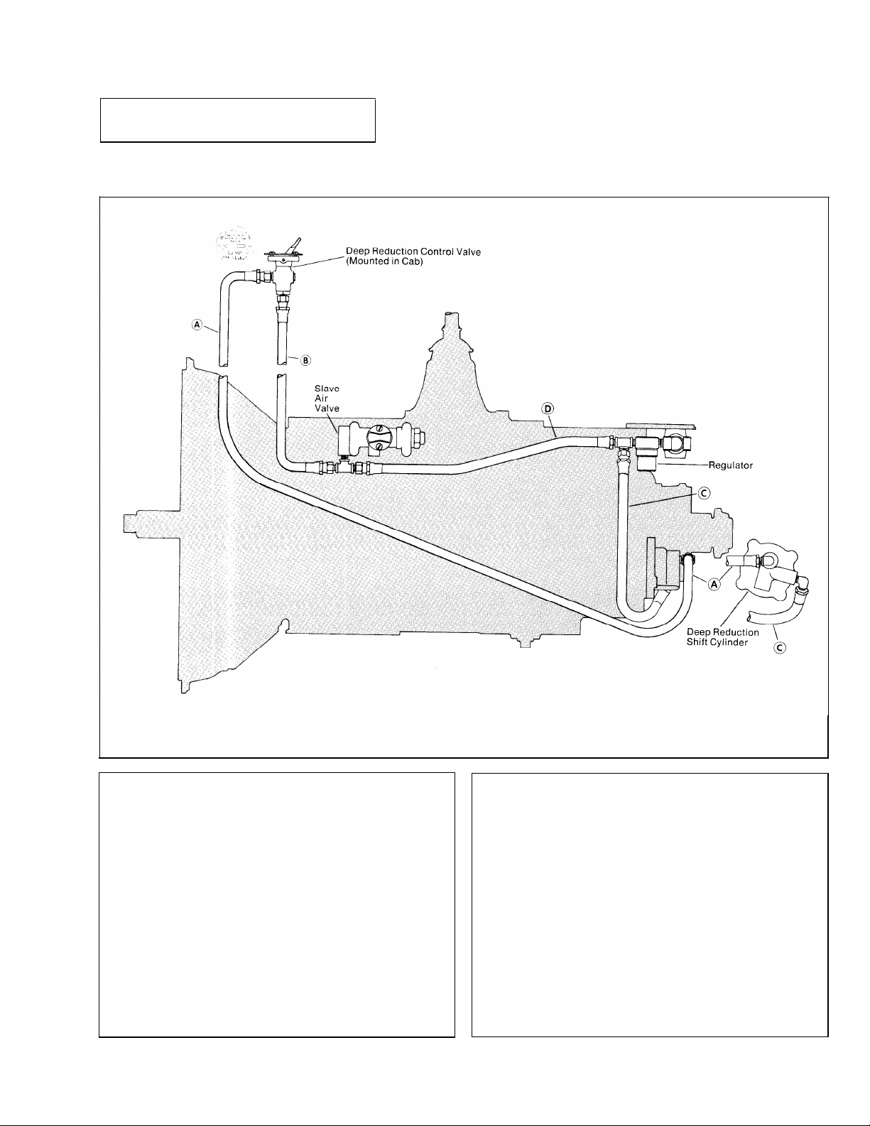
I. Deep Reduction Air Lines -
RTO-1258LL
(Range Shift Air Lines Omitted for Clarity)
A. REMOVAL
1. Disconnect the signal air line (A) and the supply
air line (B) from between the transmission and the
deep reduction control valve mounted in the cab.
2. Disconnect the 1/4" ID deep reduction shift cylinder
supply air line (C) from between the shift cylinder and
the tee fitting forward of the regulator.
3. Disconnect the 1/4" ID slave air valve supply line
(D) from between the slave air valve and the tee fitting
forward of the regulator.
B. INSTALLATION
1. Install the 18" 1/4" ID slave air valve supply line
(D) between the slave air valve and the tee fitting for-
ward of the regulator.
2. Install the 17" supply air line (C) between the fitting
forward of the regulator and the deep reduction shift
cylinder.
3. Install the control valve supply air line (B) between
the slave air valve and the "IN" port of the control
valve.
4. Install the signal air line (A) between the deep reduction shift cylinder and the "OUT" port of the control valve.
8
Page 10

II. Splitter Gear Air Lines -
RT-12513 Series (Two Position Valve)
(Range Shift Air Lines Omitted for Clarity)
A. REMOVAL
1. Disconnect the white 1/8" OD supply air line (A)
from between the tee fitting on the slave air valve and
the "S" port on the selector valve.
2. Disconnect the black 1/8" OD signal air line (B)
from between the splitter shift cylinder and the "D"
port of the selector valve.
3. Disconnect the 1/4" ID supply air line (C) from
between the tee fitting forward of the regulator and the
splitter shift cylinder.
4. Disconnect the 18" 1/4" ID slave air valve supply
line (D) from between the air valve and the tee fitting
forward of the regulator.
B. INSTALLATION
1. Connect the 18" 1/4" ID supply air line (D) between
the slave air valve and the tee fitting forward of the
regulator.
2. Connect the 1/4" ID supply air line (C) between
the splitter shift cylinder and the tee fitting forward of
the regulator.
3. Connect the black 1/8" OD signal air line (B) between the splitter shift cylinder and the "D" port of
the selector valve.
4. Connect the white 1/8" ID supply air line (A) between the tee fitting on the slave air valve and the "S"
port on the selector valve.
9
Page 11
Shifting Controls - continued
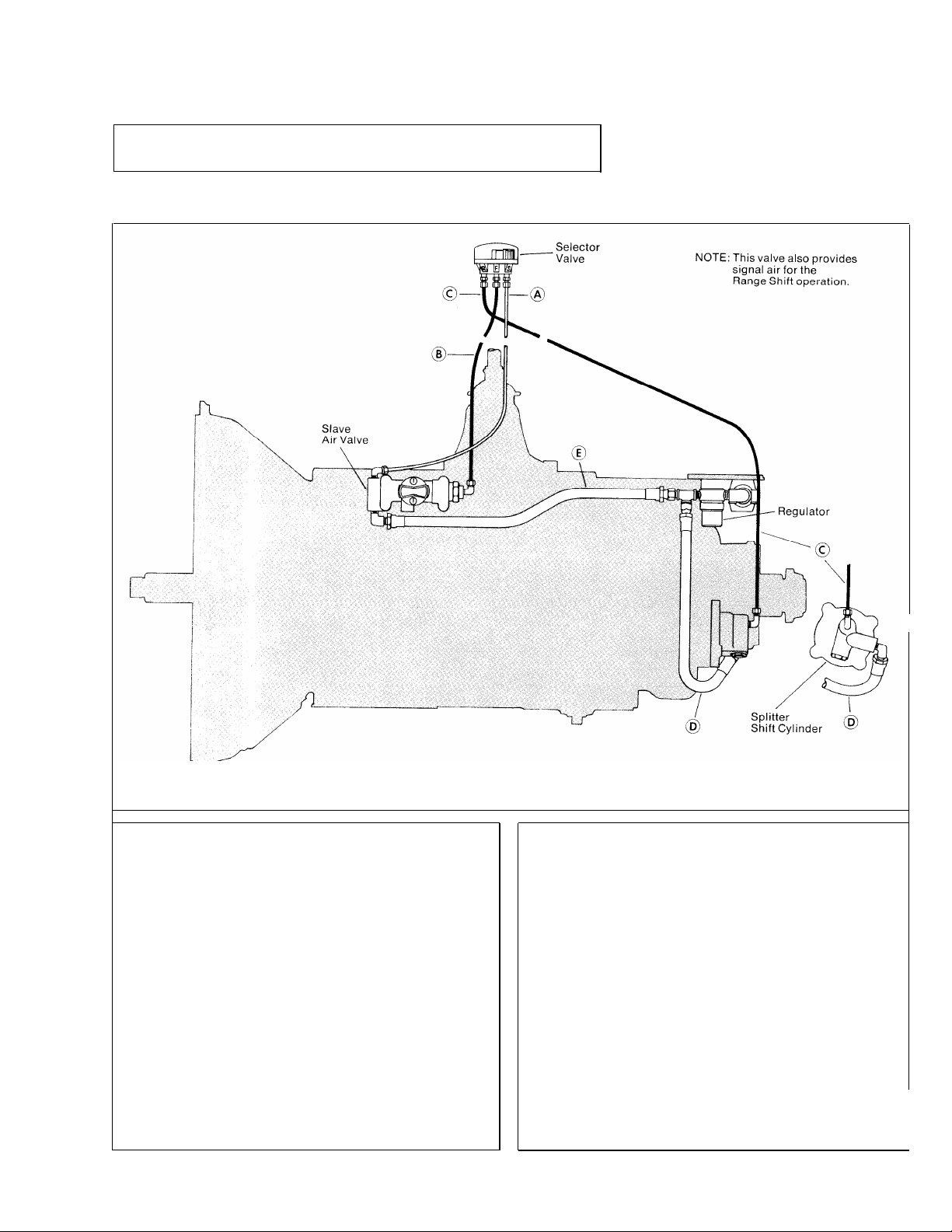
III. Splitter Gear Air Lines -
RT-12513 Series (Three position valve)
(Range Shift Air Lines Omitted for Clarity)
A. REMOVAL
1. Disconnect the white 1/8" OD supply air line (A)
from between
2. Disconnect the black 1/8" OD range shift signal air
line (B) from between the slave air valve and the
selector valve.
3. Disconnect the black 1/8"
air line (C) from between the selector valve and the
splitter shift cylinder.
4.
Disconnect the "A" OD supply air line (D) from
between the splitter shift cylinder and the tee fitting
forward of the regulator.
5.
Disconnect the 1/4" ID slave air valve supply line
(E) from between the slave air valve and the tee fitting
forward of the regulator.
the slave air valve and the selector valve.
OD splitter shift signal
B. INSTALLATION
1. Install the 18" 1/4" ID supply air line (E) between
the slave air valve and the tee fitting forward of the
regulator.
2. Install the 17" 1/4" ID supply air line (D) between
the splitter shift cylinder and the tee fitting forward of
the regulator.
3. lnstall the 1/8" OD signal air line (C) between the
splitter shift cylinder and the "R" port of the selector
valve.
4. Install the 1/8" OD signal air line (B) between the
slave air valve and the "F" port of the selector valve.
5. Install the 1/8"
slave air valve and the "S" port of the selector valve.
10
OD supply air line (A) between the
!
Page 12

IV. Range Shift Air Lines - All Models
—
A. REMOVAL
1. Disconnect the black and white 1/8" OD air lines
(A and B) from between the slave air valve and the
range shift control valve.
2. Disconnect the two 1/4" ID air lines from between
the slave air valve side cap and the range shift cylinder.
B. INSTALLATION
1. Disconnect the black and white 1/8" OD supply air
line between the forward port on the slave air valve
and the rear port on the range shift control valve.
2. Install the black 1/8" OD signal air line between the
rear port on the slave air valve and the forward port
on the range control valve.
3. Use the chart to install the "A" ID air lines between
the slave air valve side cap and the range shift cylinder.
11
Page 13

Shifting Controls - continued
V. Two and Three Position Selector Valves
A. REMOVAL AND DISASSEMBLY
1. Disconnect all air lines to the valve. Loosen the jam
nut securing the valve to the gear shift lever and turn
the valve from the lever.
2. Remove the three screws on the bottom of the valve
and lift the top cover from the body.
3. Remove the actuator from the top cover post and
remove the springs, seals, O-rings and detent parts
from the actuator.
B. REASSEMBLY
AND INSTALLATION
1. Refer to the drawing for proper assembly of the
springs, seals, O-ring and detent parts. Use a VERY
SMALL amount of silicone lubricant on the O-rings to
avoid clogging the valve ports.
2. Install the air lines with their sheathing and O-rings
on the gear shift lever.
3. Install the jam nut on the lever and install the selec-
tor valve. Use the jam nut to lock the valve in position
with the actuator button facing the driver's seat.
4. Install the 1/8" OD air lines.
12
Page 14
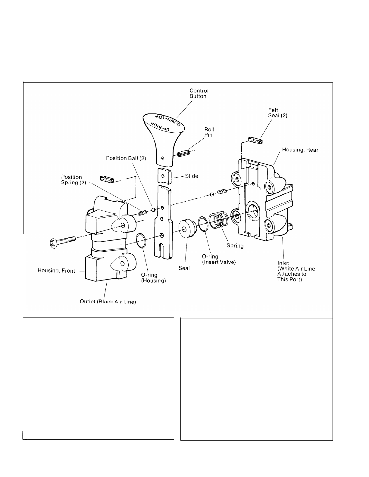
VI.
Range Control Valve
.
A. REMOVAL AND DISASSEMBLY
1. Disconnect the air lines and loosen the clamp securing the valve to the gear shift lever. Remove valve.
2. Remove the four screws to separate the front and
rear housings and remove the slide and two sets of
position springs and balls.
3. Remove the valve plate, insert O-rings and wave
washer from the valve bodies.
4. If necessary, remove the two felt seals. Punch out
the roll pin to remove the button from the slide.
B. REASSEMBLY
AND INSTALLATION
1. Refer to the drawing for proper reassembly. Use a
VERY SMALL amount of silicone lubricant on the
O-rings to avoid clogging the ports. A small amount of
grease on the position springs and balls will help to
hold them in place during reassembly.
2. Install the air lines with their sheathing and O-rings
on the gear shift lever.
3. Secure the valve on the gear shift lever with the
clamp. The control button should face to the front and
be approximately 6“ below the centerline of the shift
knob or selector valve.
4. Attach the air lines.
13
Page 15
Shifting Controls - continued
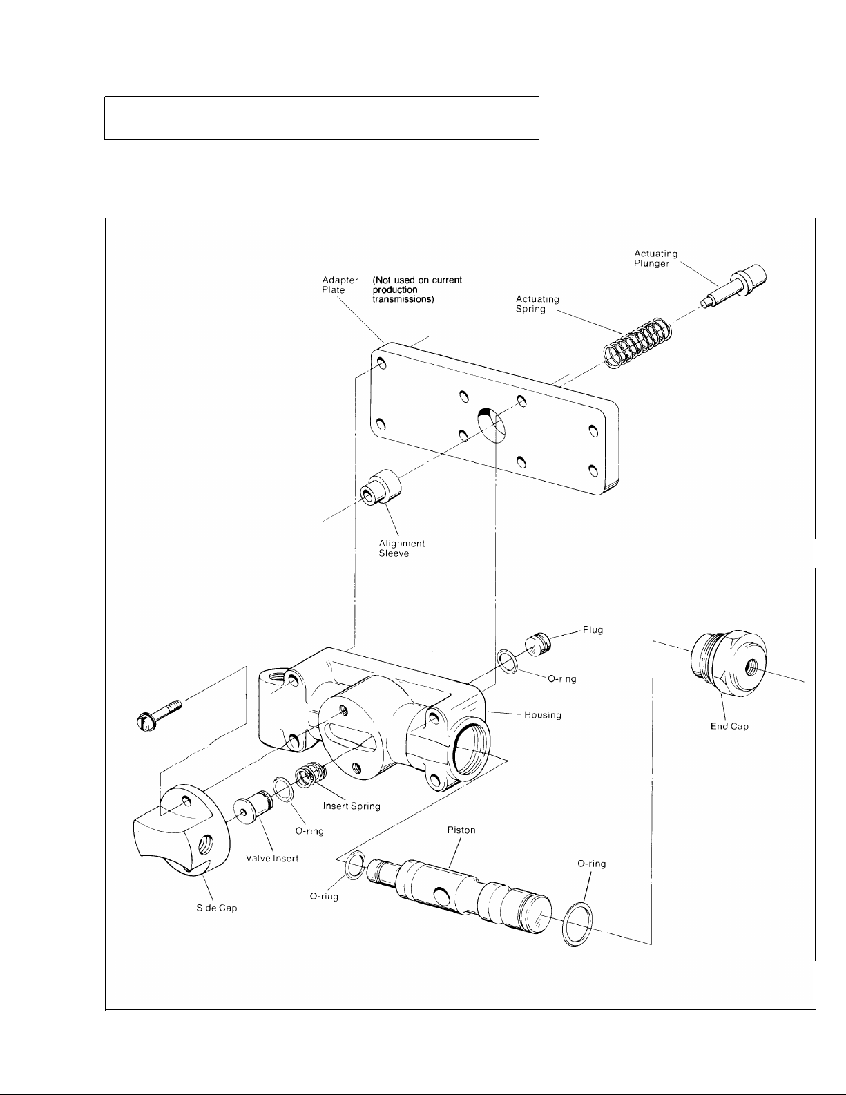
VII.
Slave Air Valve - All Models
14
Page 16
A. REMOVAL AND DISASSEMBLY
1. Turn out the four capscrews, jar lightly to break the
gasket seal and remove the air valve from the adapter
plate.
2. Remove the alignment sleeve which will be either in
the adapter plate bore or on the back of the air valve.
5. Remove the insert spring from the piston.
3. Chuck the valve in a vise by the top and bottom and
remove all brass fittings if necessary. Turn out the two
screws and remove the side cap.
4. Remove the valve insert from the piston and remove
the O-ring from the valve insert.
6. Turn the end cap from the valve body and remove
the piston from the bore.
7. Remove the two O-rings from the piston.
8. Remove the nylon plug from the piston and remove
the O-ring from the plug.
9. Remove the actuating spring and plunger from the
adapter plate or case bore.
10. If so equipped, turn out the two Allen head screws
and two capscrews and remove the adapter plate from
the transmission side.
15
Page 17

Shifting Controls - continued
VII. Slave Air Valve - All Models
B. REASSEMBLY AND INSTALLATION
I
1. If so equipped, install the adapter plate and gasket
on the transmission with the two Allen head screws and
two capscrews. Use the alignment sleeve to make sure
that the bore in the adapter plate lines up properly with
the case bore.
2. Install the actuating plunger in the plate bore with
the small end facing out.
3. Install the actuating spring over the plunger.
1
4. Install the O-rings on the piston and apply a thin
coat of silicone lubricant. Install the piston in the valve
body with the large end facing out and the piston bore
lined up with the slot in the side cap mounting surface.
5. Install the O-ring on the plug and apply a thin coat
of silicone lubricant. Insert the plug into the piston
bore with the flat surface facing out.
7. Apply a thin coat of Lubriplate to the machined face of
the side cap and install the side cap on the valve body.
8. Install the end cap on the valve body. DO NOT use
more than 40 lbs.-ft. of torque or the end cap will bind
the piston.
6. Install the insert spring in the bore. Install the O-ring
on the valve insert and apply a thin coat of silicone
lubricant. Install the valve insert in the bore with the
large end facing out.
9. Install the alignment sleeve in the bore in the back of
the valve and install the valve and gasket on the adapter
plate. If previously removed, install the brass fittings on
the valve.
16
Page 18

VII. Filter/Regulator Assembly - All Models
* Not used with RT-12509 Series Transmissions
A. REMOVAL AND DISASSEMBLY
1. Turn out the two retaining capscrews and remove
the assembly from the transmission.
2. Turn out the two clamp nuts and remove the filter/
regulator assembly from the bracket.
3. Remove the fittings and if necessary, turn the regu-
lator from the filter.
4. If necessary, turn the end cap from the filter to remove the filter core. Use caution as the end cap is
spring loaded.
B. REASSEMBLY
AND INSTALLATION
1. Refer to the drawing for reassembly of the air filter.
2. Secure the nipple and regulator to the "OUTLET"
port of the filter. Note that the larger of the two bores
on the regulator attaches to the filter.
3. Secure the filter to the bracket with the "U" clamp,
nuts and lockwashers.
4. Install the two range shift air lines between the slave
air valve and the range shift cylinder and secure the
filter/regulator assembly to the auxiliary housing with
the two capscrews.
17
Page 19

Shifting Controls - continued
IX. Gear Shift Lever Housing - All Models
OLD STYLE
NEW STYLE
18
Page 20
A. REMOVAL AND DISASSEMBLY
B. REASSEMBLY
AND INSTALLATION
1. Turn out the capscrews, jar lightly to break the gasket seal and remove the gear shift lever housing from
the shift bar housing.
1. Install the spade pin or pivot pin, nut and washer in
the bore in the housing. If previously removed, install
the O-ring in the groove.
2. Install the gear shift lever in the housing, fitting the
slot in the lever ball over the spade pin.
3. Place the tension spring washer over the lever ball
with the dished side up:
2. Secure the housing in a vise and use a large screw-
driver to twist between the spring and side of the hous-
ing, forcing the spring from under the three lugs. Do
one coil at a time. Remove the spring.
3. Remove the washer and gear shift lever.
4. Remove the spade pin or pivot pin, nut and washer
from the bore in the housing. If necessary, remove the
O-ring from the housing.
4. Seat the tension spring under the lugs in the housing,
seating one coil at a time. Use of a spring driving tool
is recommended.
5. Make sure that the three tension springs and balls
are in the shift bar housing bores and install the gear
shift lever housing and gasket on the shift bar housing.
19
Page 21

Shifting Controls - continued
X. Shift Bar Housing - All Models
20
Page 22

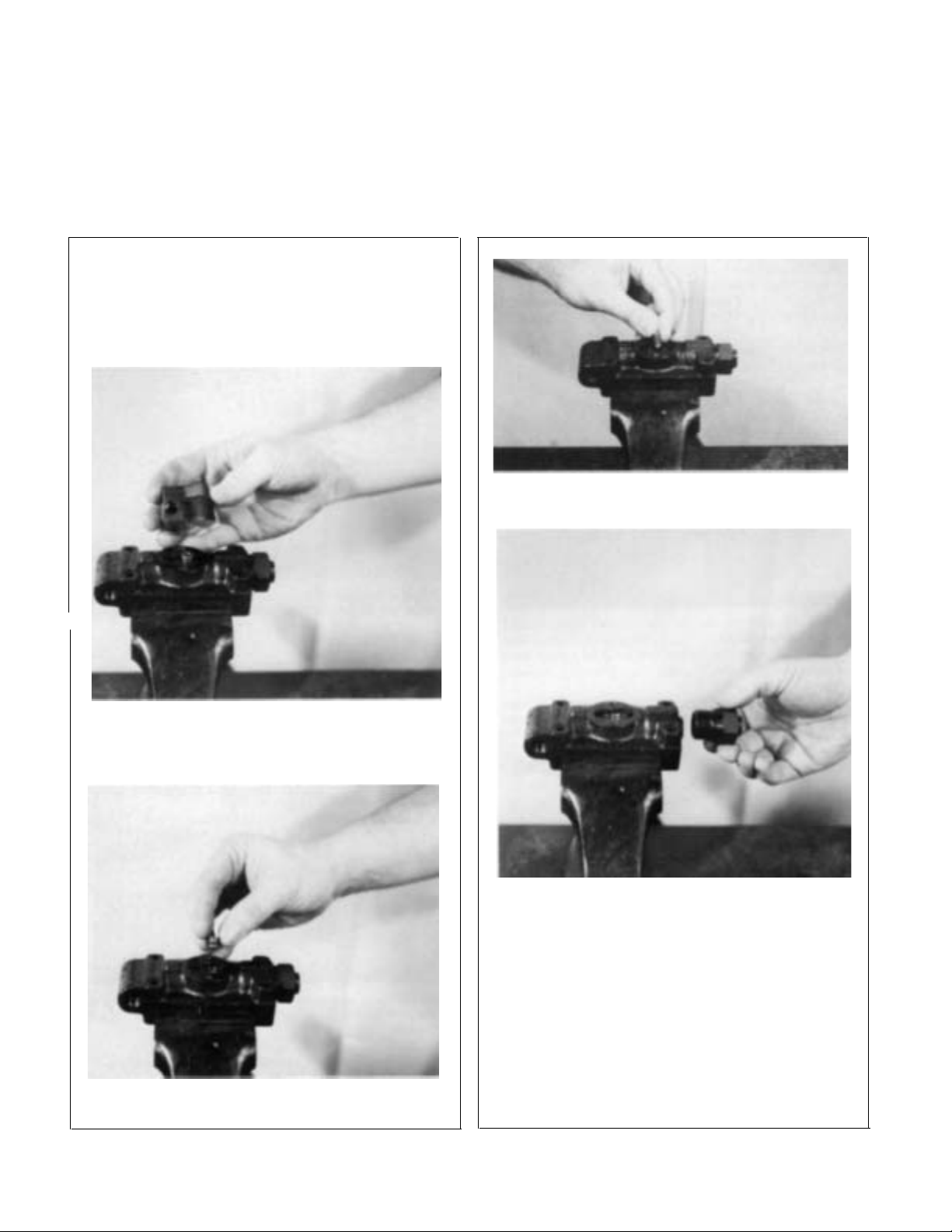
A. REMOVAL AND DISASSEMBLY
1. Make sure that the shift bars are in the neutral position. Remove the three tension springs, (arrow ). Turn
out the retaining capscrews, jar lightly to break the gasket seal and lift the shift bar housing from the front
case. Remove the three tension balls from the housing
bores by tipping the housing slightly.
4. Remove the actuating plunger.
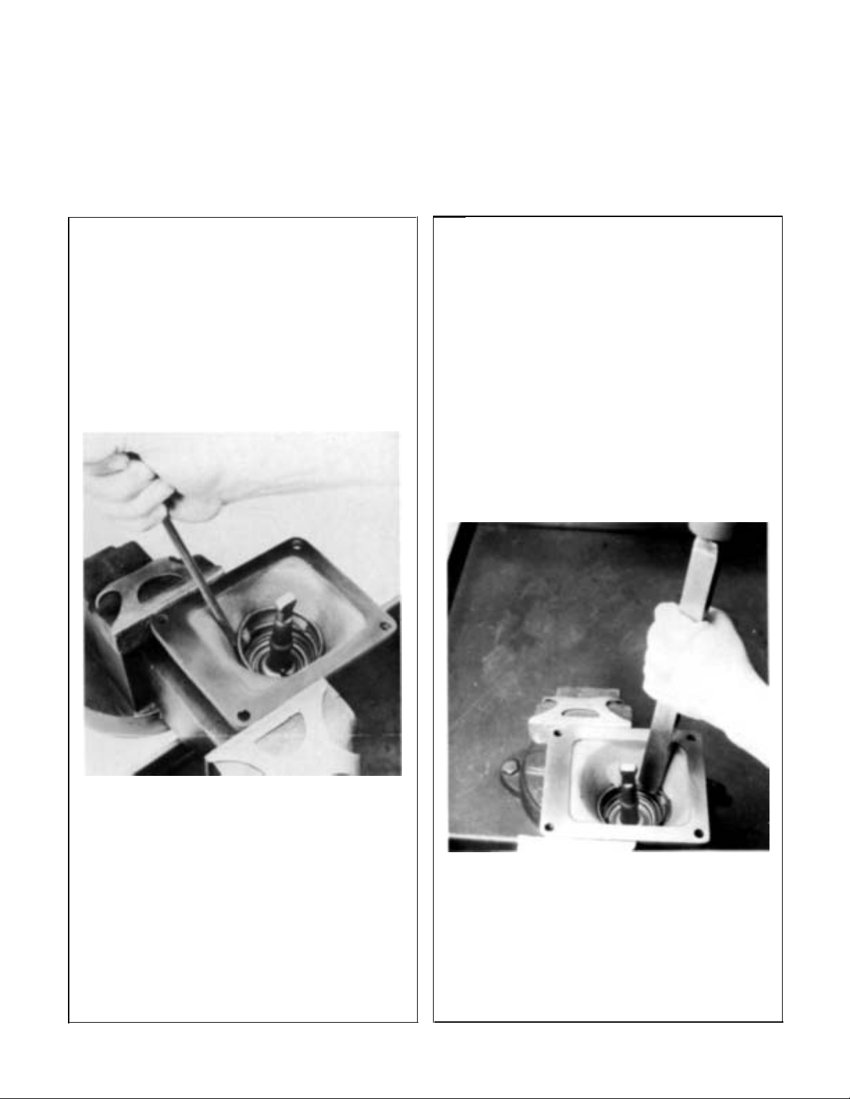
2. Mount the housing in a vise using caution to avoid
marring the machined mounting surface. If so equipped,
remove the oil trough. Cut and remove all of
lockwires. Turn out the lockscrews and remove the direct speed shift bar, yoke and block.
-
the
3. Turn out the lockscrews and remove the 2nd speed
shift bar, yoke and block. As the notch clears the hous-
ing boss, remove the interlock pin, (arrow).
5. Turn out the lockscrew and remove the reverse speed
shift bar and yoke. If necessary, turn out the plug on
the yoke and remove the spring and plunger. Use caution as the plug is spring loaded.
6. Remove the two interlock balls from the bore in the
housing boss.
21
Page 23

Shifting Controls - continued
X. Shift Bar Housing
B. REASSEMBLY AND INSTALLATION
1. If previously removed, install the reverse-stop
plunger in the reverse yoke. Make sure that the plunger
is fully seated in the bore.
2. Install the spring in the bore and on the plunger.
4. Install the reverse shift bar and yoke. Install the yoke
lockscrew; tighten and wire securely.
5. Install the actuating plunger.
3. Apply adhesive sealant to the plug threads and partially
install the plug. Use the tip of the gear shift lever to push
the plunger back into the bore to compress the spring.
Tighten the plug fully and then back off 1/2 - 1-1/2 turns.
Stake the plug threads in the hole.
6. Install one of the two interlock balls in the housing
bore, making sure that the ball goes all the way to the
bottom of the bore and rests on the reverse shift bar.
22
Page 24

.
7. Install the 2nd speed shift bar, yoke and block, in-
serting the interlock
-
pin in the neutral notch of the bar,
(arrow). Install the yoke and block lockscrews; tighten
and wire securely. On "F" model transmissions, use the
short lockscrew in the shift block.
8. Install the remaining interlock ball,
10. Install the three tension balls; one in each bore.
11. Install the shift bar housing and gasket on the
front case, fitting the yoke slots into the mainshaft
sliding clutch gears. The shift bars and clutches must
be in the neutral position. Install the three tension
springs in the bores.
9. Install the direct speed shift bar, yoke and block. Install lockscrews and wire securely. If so equipped, install
the oil trough with the two lockscrews and wire securely.
.
12. Secure the housing with the retaining capscrews.
I
23
Page 25

Auxiliary Sections
I. Removal and lnstallation -
All Models
A. REMOVAL FROM FRONT CASE
NOTE:
The RT-12513 auxiliary section is shown in
the following steps. However, the procedure is
the same for RT-12509 series and RTO-
1258LL transmissions.
3. Turn out the capscrews securing the auxiliary section to the front case.
1. If not previously removed, use two clutches in the
front case to lock the transmission in two gears and use
a large breaker bar to turn the output shaft nut from
the output shaft.
2. Remove the stop nut washer and companion flange or
yoke from the splines of the output shaft.
4. insert three puller screws in the tapped holes in the
auxiliary section flange and tighten evenly to move the
auxiliary approximately 1/2" to the rear.
5. Attach a lifting bracket at the top center of the auxiliary section. Move the auxiliary to the rear and off the
front case dowel pins. Mount the auxiliary in a vise
using caution to avoid damage to the machined surface
of the flange.
24
Page 26

B. INSTALLATION ON THE FRONT CASE
1. Install the gasket on the front case. Attach a lifting
bracket and chain hoist to the top center of the auxiliary
section and guide the section on to the front case dowel
pins. The two auxiliary countershafts will mesh with
the drive gear and the front of each shaft will seat in
the two bearings installed in the front section. Move
the assembly evenly, rotating the drive gear, if necessary, to properly mesh gears.
3. Install the speedometer drive gear or replacement
spacer on the hub of the flange or yoke. Install the
flange on the splines of the output shaft.
NOTE:
The auxiliary section can also be installed by
setting the front section vertically on wood
blocks and lowering the auxiliary section onto
the front case with a chain hoist attached to an
output shaft lifting bracket. This procedure is
recommended for installation of the RTO-
1258LL auxiliary section due to the extreme
length and weight of the countershaft assemblies.
2.
With
the
auxiliary section fully
into position against the
front case, install the capscrews.
4. Lock the front case by engaging two sliding clutches
and secure the flange or yoke with the elastic stop nut,
using 450-500 lbs./ft. or torque. The nut should be
pre-lubricated.
25
Page 27

Auxiliary Sections - continued
II. RT-12509 Auxiliary Section Disassembly
A. REMOVAL AND DISASSEMBLY
OF THE RANGE SHIFT CYLINDER ASSEMBLY
1. Turn out the four capscrews and remove the shift
cylinder cover. Remove the nut from the end of the
yoke bar.
2. Cut the lockwire and turn out the two yoke lock-
screws.
3. Pull the yoke bar forward and out of the housing. Re-
move the piston from the cylinder bore and if necessary,
remove the O-rings from the ID and OD of the piston.
4. Remove the shift yoke, turn out the four capscrews
and remove the cylinder housing from the auxiliary
plate. If necessary, remove the O-ring from the bore in
the housing.
26
Page 28

B. REMOVAL OF THE
AUXILIARY COUNTERSHAFTS
1. Turn out the capscrews and remove the two countershaft rear bearing covers. Remove the snap ring from
the rear of each countershaft.
C. REMOVAL AND DISASSEMBLY
OF THE SYNCHRONIZER
ASSEMBLY
2. Pull the synchronizer assembly forward and from the
splines of the output shaft.
2. Use a soft bar and mall to drive the countershafts
forward and from the rear bearings. Use a soft bar to
tap the bearings to the rear and from the auxiliary
plate. Tap on the outer race to avoid damaging the
bearings.
2. Pull the direct ring from the blocker pins of the low
speed ring; cover the assembly with a cloth during this step to
avoid losing the three springs which will be released from
the direct ring. Remove the sliding clutch gear from
the low speed ring.
27
Page 29

Auxiliary Sections - continued
II. RT-12509 Auxiliary Section Disassembly
D. REMOVAL AND DISASSEMBLY
OF THE LOW SPEED GEAR AND OUTPUT SHAFT
1. Use a soft bar and mall to drive the output shaft for-
ward and from the rear bearing.
2. Remove the bearing inner spacer from the shaft.
28
Page 30

3. Using the front face of the low speed gear as a base,
press the shaft through the gear and bearing. If necessary, remove the snap ring from the ID of the gear.
5. Remove the two bearing cups and outer spacer from
the auxiliary plate bore.
4. Turn out the cpascrews and remove the rear bearing
housing. If necessary, remove the oil seal from the housing. Remove the rear bearing cone from the housing.
29
Page 31

Auxiliary Sections - continued
III. RT-12509 Auxiliary Section Reassembly
A. REASSEMBLY OF THE LOW SPEED GEAR AND OUTPUT SHAFT
1. Place the output shaft on a bench with the threaded
end up and install the splined spacer on the shaft, large
diameter down.
2. Mark any two adjacent teeth on the low speed gear
and then mark the two teeth directly opposite.
3. Install the low speed gear on the shaft with the clutching teeth down and engaging the splines of the spacer.
4. Install the washer on the shaft, flat surface down.
30
Page 32

5. Heat and install the front bearing cone on the shaft
and against the washer, taper up. The two bearing
cones and cups are a matched set. Make sure that the
correct cone for cup is used as indicated by markings.
7. Place the front cup into the housing bore with the
thick end up.
NOTE:
Heating of the bearing cones is recommendcd, provided the bearing is not heated over
o
F. Heat lamps are recommended as a
275
heating source.
6. Install the bearing inner spacer on the shaft and
against the bearing cone.
I
8. Stack the outer spacer and i-car cup, shoulder up,
on the front cup and tap all three evenly into the bore
until the shoulder of the rear cup seats against the
auxiliary plate.
31
Page 33

Auxiliary Sections - continued
III. RT-12509 Auxiliary Section Reassembly
A. REASSEMBLY OF THE LOW SPEED GEAR AND OUTPUT SHAFT.
9. Heat and install the rear bearing cone, taper to the inside.
NOTE: Heating of the bearing will facilitate installation. Do not heat the bearing over 275oF.
11. Install the rear bearing housing over the output shaft
and against the rear plate. If the transmission is equipped with a speedometer drive gear, the gear must be installed on the output shaft prior to the installation of the
rear bearing housing.
capscrew intersecting the speedometer drive gear bore.
Use a brass washer on the
10. If previously removed, install the oil seal in the rear
bearing housing. Side with the seam to the inside.
32
Page 34

B. REASSEMBLY OF THE SYNCHRONIZER ASSEMBLY
1. Place the larger (low speed) brass synchronizer ring
on a bench with the pins facing up and install the
sliding clutch gear over the ring, protruding clutching
teeth down.
4. Apply pressure to the direct ring while twisting
counterclockwise to fully seat the direct ring on the
I
low speed ring pins.
2. Install the three springs in the direct ring,
3. Install the direct ring on the low speed ring pins,
seating the springs against the pins.
I
5. Mount the auxiliary plate in a vise in the upright
position and install the synchronizer assembly on the
output.
33
Page 35

Auxiliary Sections - continued
1
III. RT-12509 Auxiliary Section Reassembly
C. TIMING AND INSTALLATION OF THE AUXILIARY
COUNTERSHAFT ASSEMBLIES
1. On the small diameter low range gear of each countershaft, mark the tooth which is stamped with an "O".
2. Place one of the countershafts into position in the rear
plate, meshing the marked tooth on the countershaft between two of the marked teeth on the low speed gear. Use
a soft bar to start the rear bearing onto the shaft and into
the case bore and use a bearing driver to complete the
installation. Check the synchronizer assembly during
bearing installation to make sure that the springs do not
pop out. Repeat the procedure for the remaining countershaft.
NOTE: Make sure that the bearing inner race is installed on teh front of each auxiliary countershaft.
3. Install the snap ring on the rear of each countershaft.
4. Install the countershaft rear bearing covers.
34
Page 36

D. INSTALLATION OF THE RANGE SHIFT CYLINDER ASSEMBLY
1. Install the cylinder housing and gasket in the rear
plate with the air fitting facing up. If previously removed, install the O-ring in the bore in the cylinder and
coat the O-ring with a thin application of silicone lubricant.
3. Install the O-rings in the OD and ID of the piston,
apply a thin coat of silicone lubricant to the O-rings
and install the piston on the yoke bar and in the cylinder housing bore with the flat side facing out.
2. Install the shift yoke on the sliding clutch gear of the
synchronizer and insert the yoke bar through the yoke
and cylinder housing. Secure the yoke to the bar with
the two yoke lockscrews; tighten and wire securely.
4. Secure the piston to the yoke bar with the nut. Install the gasket and voer with the air fitting to the top.
35
Page 37

Auxiliary Sections - continued
IV. RTO-1258LL Auxiliary Section Disassembly
A. REMOVAL AND DISASSEMBLY
OF THE RANGE SHIFT CYLINDER ASSEMBLY
,
1. Turn out the four capscrews and remove the range
shift cylinder cover. Remove the nut from the end of
the yoke bar.
2. Cut the lockwire and turn out the two yoke lockscrews.
3. Remove the piston from the yoke bar and if necessary,
remove the O-rings from the ID and OD of the piston. Push
the yoke bar forward and from the housing.
4. Remove the shift yoke, turn out the four capscrews
and remove the cylinder housing from the auxiliary
housing. If necessary, remove the O-ring from the bore
in the cylinder housing.
6
3
Page 38

B. REMOVAL OF THE
AUXILIARY COUNTERSHAFTS
1. Turn out the capscrews and remove the two countershaft rear bearing covers. Remove the snap ring from
the rear of each countershaft.
C. REMOVAL AND
DISASSEMBLY OF THE
SYNCHRONIZER ASSEMBLY
l. Pull the synchronizer assembly from the splincs of
the range mainshaft.
2. Use a soft bar and mall to drive each countershaft
forward and from the rear bearing. Use a soft bar to tap
the bearings to the rear and from the housing bores.
Tap on the outer races to avoid damaging the bearings.
NOTE:
When driving the countershafts, check the
synchronizer assembly periodically to make
sure that the direct ring is not moving forward. If the direct ring is allowed to slide off
the low speed ring blocker pins, the three
springs in the assembly could jump out of the
bores and get lost.
2. Pull the direct ring from the blocker pins of the low
speed ring. Cover with a cloth as the three pins will be
released at the blocker pin locations. Remove the sliding clutch gear from the pins of the low speed ring.
37
Page 39

Auxiliary Sections - continued
III. RTO-1258LL Auxiliary Section Disassembly
D. REMOVAL OF THE LOW SPEED GEAR
1. Remove the key from the keyway between the splines
of the range mainshaft.
2. Turn the splines of the low speed gear washer, located in the hub of the gear, to align with the spline of
the shaft. Remove the gear and washer from the shaft.
Remove the coupler which is located on the shaft be-
hind the gear.
38
Page 40

E. REMOVAL OF THE DEEP REDUCTION SHIFT CYLINDER
1. Remove the shift cylinder cover.
2. Cut the lockwire and turn out the lockscrew from
the shift yoke.
3. Push the yoke bar to the rear and remove from the
housing. If necessary, remove the O-ring from the bar,
(arrow).
4. Remove the shift yoke and cylinder housing from
the auxiliary housing. If necessary, remove the O-ring
from the bore in the cylinder housing.
39
Page 41

Auxiliary Sections - continued
IV. RTO-1258LL Auxiliary Section Disassembly
F. REMOVAL OF THE RANGE MAINSHAFT
1. Remove the snap ring from the front of the quill.
NOTE: Snap ring used on current production models must
be removed by spreading with a screwdriver.
2. Move the sliding clutch forward and against the snap
ring of the range mainshaft. Insert jaws of puller behind
sliding clutch gear and pull the mainshaft from the quill.
3. Remove the bearing from the shaft. If necessary, use
an inside jaw impact puller.
4. Remove the snap ring from the OD of the mainshaft
and, if necessary, press the bushing from the mainshaft
bore, (arrow).
40
Page 42

G. REMOVAL OF THE DEEP REDUCTION GEAR
AND OUTPUT SHAFT ASSEMBLY
1. Turn out the capscrews and remove the rear bearing
housing. If necessary, remove the oil seal from the housing.
2. Remove the snap ring from the output shaft.
4. Use a soft bar and mall to drive the output shaft forward and from the auxiliary housing.
5. Use the deep reduction gear as a base to press the rear
bearing from the output shaft. This will free the gear,
washer, spacer and oil deflector.
3. Remove the speedometer drive gear or replacement
spacer from the shaft.
6. Remove the two bearing cups and outer spacer
the auxiliary housing bore.
41
Page 43

Auxiliary Sections - continued
V. RTO-1258LL Auxiliary Section Reassembly
A. REASSEMBLY OF THE DEEP REDUCTION GEAR AND OUTPUT SHAFT
I
I
I
1. Place the output shaft on blocking with the threaded
end up. Use caution to avoid damage to the quill.
2. Install the splined spacer on the shalt.
I
42
Page 44

3. Mark any two adjacent teeth on the reduction gear
and then mark the two teeth directly opposite.
4. Install the reduction gear on the shaft and spacer with
the clutching teeth down.
5. Install the washer on the shaft and against the gear
with the side with the large groove facing up.
6. Install the oil deflector in the rear housing bore with
the cupped surface facing up. Use a large bearing driver
to drive the deflector down until the top surface of the
deflector is 2" below the machined surface of the output
shaft bore.
NOTE: If available, use two bearing outer spacers
stacked on top of each other to drive the oil deflector into
the bore. The deflector will be at the proper depth when
the top of the top spacer is flush with the machined surface of the output shaft bore.
43
Page 45

Auxiliary Sections - continued
V. RTO-1258LL Auxiliary Section Reassembly
A. REASSEMBLY OF THE DEEP REDUCTION GEAR AND OUTPUT SHAFT (Cont.)
7. Install the rear housing over the output shaft, allowing
the housing to rest on the reduction gear.
8. Heat the front bearing cone and install in the bore and
against the oil deflector with the cone surface facing up.
NOTE: Heating off the bearings will facilitate installation. Do not heat the bearings over 275
o
F.
9. Install the bearing inner spacer on the shaft and
against the front bearing cone.
10. Stack the two bearing cups and outer spacer in the
output shaft bore in the proper sequence. Make sure that
the front bearing cup taper matches the taper direction
ofÍ the front bearing cone.
44
Page 46

11. Tap the two cups and outer spacer lightly and evenly
into the case bore until the lip of the rear cup seats
against the machined surface. It will be necessary to
block under the rear housing slightly to permit the output shaft assembly to more far enough.
12. Heat and install the rear bearing cone on the shaft
and in the rear cup, taper facing down.
14. If previously removed, install the oil seal in the rear
bearing housing with the seam to the inside. Use of a
proper oil seal driver is recommended.
.
.
15. Install the rear bearing housing and gasket on the
auxiliary housing, using a brass washer (arrow), at the
speedometer bore. Make sure to match one ofÕ the
notches in the surface of Õthe bearing housing with the oil
port in the auxiliary housing.
13. Install the speedometer drive gear or replacement
spacer on the shaft and against the rear bearing cone and
secure with the snap ring.
16. Install the sliding clutch gear on the front of the
shaft, internal clutching teeth to the rear.
45
Page 47

Auxiliary Sections - continued
V. RTO-1258LL Auxiliary Section Reassembly
B. INSTALLATION OF THE RANGE MAINSHAFT ASSEMBLY
3. Install the bearing in the mainshaft and on the quill.
A 3/4" socket can be used to install the bearing keeping
the socket centered on the inner race and tapping lightly with a soft bar.
1. If previously removed, install the snap ring in the
groove on mainshaft. Install the bushing in the shaft by
driving or pressing until the top of the bushing is flush
with the bottom of the chamfer cut in the mainshaft
bone, (arrow).
2. Install the mainshaft on the quill of the output shaft,
seating the bushing on teh rear surface of the quill.
4. Install the snap ring on the front of the quill. Use of
the proper snap ring driver is recommendcd. (See tool
reference section ).
46
Page 48

C. REASSEMBLY AND INSTALLATION
OF THE DEEP REDUCTION SHIFT CYLINDER
1. Install the O-ring in the bore of the shift cylinder and
install the cylinder in the auxiliary housing with the air
channel to the right.
2. Install the yoke in the sliding clutch yoke slot with the
lockscrew hole facing up.
3. Install the O-ring in the yoke bar groove and push the
yoke bar forward and through the cylinder housing and
the shift yoke. Install the yoke lockscrew; tighten and
wire securely.
4. Install the cylinder cover, aligning the air channel
with the channel in the cylinder housing.
47
Page 49

Auxiliary Sections - continued
V. RTO-1258LL Auxiliary Section Reassembly
D. INSTALLATION OF THE LOW SPEED GEAR
1. Install the coupler on the shaft, large diameter to the
rear.
2. Install the low speed gear on the shaft and against
the coupler, dished side to the front.
3. Install the splined washer on the shaft and in the
hub of the gear. Turn the washer to lock the gear on
the shaft. Washers with varying thicknesses are available.
Use the washer which provides the tightest fit.
4. Install the key in the keyway, inserting the thick end
between the splines of the washer.
48
Page 50

E. REASSEMBLY AND INSTALLATION OF THE SYNCHRONIZER ASSEMBLY
1. Place the low speed ring on a workbench with the
pins facing up. Install the sliding clutch on the low
speed ring with the dished side up.
3. Apply pressure to the dircct ring and twist to compress the springs and seat the ring fully on the pins. It
maybe helpful to place the assembly on a rag during
this step to prevent the ring on the bottom from turning.
2. Coat the three synchronizer springs with grease to
hold them in place and install in the three bores in the
direct ring. Place the ring over the pins of the low speed
ring with the springs against the blocker pins.
4. Install the synchronizer on the range mainshaft with
the low speed ring seated fully into the low spced gear
bore.
49
Page 51

Auxiliary Sections - continued
V. RTO-1258LL Auxiliary Section Reassembly
F. TIMING AND INSTALLATION OF THE AUXILIARY COUNTERSHAFTS
1. Mark the tooth which is stamped with an "o" on each
of the three sets of gears on the auxiliary countershafts.
2. Place one of the countershafts into position in the case,
meshing the marked teeth on the shaft between one of the
sets of marked teeth on each of the gears. Hold the countershaft in position and use a soft bar to tap the rear bear-
ing onto the shaft and into the case bore. Use a bearing
driver to complete installation of the bearing. Check the
synchronizer during bearing installation to make sure
that the springs do no pop out. Repeat the procedure to
install the remaining countershaft.
3. Install the snap ring in the groove on the rear of each
countershaft.
4. Install the two rear bearing covers.
IMPORTANT: Make sure that the bearing inner race is
installed on the front of each countershaft.
50
Page 52

G. REASSEMBLY AND INSTALLATION OF THE RANGE SHIFT CYLINDER
1. If previously removed, install the O-ring in the bore
of the shift cylinder and apply a thin coat of silicone
lubricant. Install the cylinder and gasket in the auxiliary housing bore with the air fitting to the top.
2. Hold the shift yoke in position on the synchronizer
clutch gear with the long hub of the yoke to the rear and
insert the yoke bar, threaded end first, through the yoke
hub and shift cylinder, aligning the slots in the bar with
the lockscrew bores in the yoke hub. Install the yoke
lockscrews; tighten and wire securely.
4. Install the piston on the yoke bar, flat face out. Apply
a thin coat of silicone lubricant to the O-rings.
5. Install the nut on the end of the yoke bar; tighten
securely with 70-85 lbs. ft. of torque.
3. Install the O-rings in the OD and ID of the piston.
6. Install the cover and gasket on the cylinder with the
air fitting to the top left.
CAUTION: If a gasket is used which requires shellac
or permatex, USE ONLY A VERY SMALL
AMOUNT to prevent clogging of cylinder air ports or
damage to O-rings.
51
Page 53

Auxiliary Sections - continued
VI. RT-12513 Auxiliary Section Disassembly
A. REMOVAL AND DISASSEMBLY OF THE RANGE SHIFT CYLINDER
1. Remove the range shift cylinder cover and remove
the nut from the end of the yoke bar.
.
2. Cut the lockwire and turn out the two yoke lock-
screws.
3. Remove the piston from the yoke bar and if necessary,
remove the O-rings from the OD and ID of the piston. Push
the yoke bar forward and from the housing.
4. Remove the cylinder housing from the auxiliary
housing. If necessary, remove the O-ring from the
housing bore, (arrow). Remove the shift yoke from the
synchronizer.
52
I
Page 54

B. REMOVAL OF THE AUXILIARY COUNTERSHAFT BEARINGS
1. Remove the two countershaft rear bearing covers
and remove the snap ring from the rear of each counter-
shaft.
3. Move the countershaft back to the rear to expose
the bearing snap rings.
,
2. Use a soft bar and mall to drive the countershafts
forward approximately 1/2" to partially unseat the
bearings.
4. Use a puller to remove the countershaft rear
bearings.
C. REMOVAL AND DISASSEMBLY OF THE SYNCHRONIZER ASSEMBLY
2. Pull the direct ring from the pins of the low speed
1. Spread the countershaft and remove the syn-
chronizer.
ring. Cover the assembly with a cloth during this step
to prevent loss of the three springs. Remove the sliding
clutch gear from the low speed ring.
53
Page 55

Auxiliary Sections - continued
VI. RT-12513 Auxiliary Section Disassembly
D. REMOVAL OF THE LOW RANGE GEAR
1. Remove the key from the keyway between the splines
of the range mainshaft.
2. Turn the splines of the low speed gear washer to
align with the splints of the shaft.
3. Remove the low range gear and washer from the
shaft.
4. Remove the coupler from the shaft and remove the
right countershaft from the housing. The left countershaft cannot be removed at this time.
54
I
Page 56

E. REMOVAL AND DISASSEMBLY
OF THE SPLITTER GEAR SHIFT CYLINDER
1. Cut the lockwire and remove the yoke lockscrew.
2. Remove the cylinder cover. If necessary, turn out the
plug on the cover and remove the insert valve.
3. Pull the yoke bar from the cylinder housing; remove
the O-ring if necessary.
4. Remove the shift yoke and remove the shift cylinder
from the auxiliary housing. If necessary, remove the
O-ring from the bore in the shift cylinder. The left
countershaft may now be removed from the auxiliary
housing.
55
Page 57

Auxiliary Sections - continued
VI. RT-12513 Auxiliary Section Disassembly
F. REMOVAL AND DISASSEMBLY OF THE RANGE MAINSHAFT ASSEMBLY
1. Remove the snap ring from the front of the range
mainshaft.
2. Use a puller on the sliding clutch to remove the
mainshaft and clutch from the output shaft quill.
3. If necessary, remove the bearing from the mainshaft
by tapping lightly from the inside with the range shift
yoke bar or a similar size rod.
4. If necessary, remove the snap ring and bushing from
the mainshaft. A 15/16" socket can be used by installing the back face of the socket from the inside of the
shaft against the bushing and using a steel rod to drive
against the socket.
56
Page 58

G. REMOVAL AND DISASSEMBLY OF THE OUTPUT SHAFT
1. Use a soft bar and mall to drive the output shaft forward and from the rear housing. Do not allow the output shaft to fall on the quill, (arrow).
3. Turn out the capscrews and remove the rear bearing
cover. If necessary, remove the oil seal from the cover
with a hammer and punch. Removal procedures will
damage the seal and removal should not be attempted
unless replacement of the seal is planned.
2. Use the splitter gear as a base to press the output
shaft through the gear, washer and bearing. If necessary, remove the snap ring from the bore of the splitter
gear.
4. Remove the rear bearing cone and using a small
hammcr and punch, tap lightly to move the two bearing cups and outer spacer to the rear and from the
housing bore. Use caution to avoid marking the ma-
chined surface of the bore.
57
Page 59

Auxiliary Sections - continued
VII. RT-12513 Auxiliary Section Reassembly
A. REASSEMBLY AND INSTALLATION OF THE OUTPUT SHAFT ASSEMBLY
I
1. Place the output shaft on blocking to prevent damage
to the quill and install the stepped spacer on the shaft,
small diameter up.
2. Install the splined washer on the shaft, shoulder up.
4. Install the rear washer on the shaft, flat side up.
5. Heat the front bearing cone and install on the shaft
with the taper up. (Do not heat the bearing over
o
275
F).
NOTE:
The two bearing cones and cups are a
I
matched set. Make sure that the proper cone
is used with the proper cup.
3. If previously removed, install the snap ring in the
groove in the splitter gear. Install the splitter gear on
the shaft and over the splined washer, snap ring up.
6. Install the bearing inner spacer on the shaft.
58
Page 60

7. For timing purposes, mark any two adjacent teeth
on the gear and then mark the two teeth directly
opposite.
8. Start the front cup of the bearing into the auxiliary
bore with the wide edge up. Stack the outer spacer and
rear cup on the front cup and usc a driver to seat all
three evenly in the bore. Tap lightly to avoid driving
the front cup out the bottom of the bore.
10. Heat the rear bearing cone and install on the shaft
and in the cup. make sure that the lip of the cup is fully
seated against the housing.
11. If previously removed, instll the oil seal in the
bearing housing with the surface with the seam to the
inside.
9. Place the housing over the output shaft, seating the
bearing in the cup.
12. Install the bearing housing and gasket on the auxiliary housing; use a brass washer on the capscrew
which passes through the speedometer bore.
59
Page 61

Auxiliary Sections - continued
VII. RT-12513 Auxiliary Section Reassembly
B. REASSEMBLY AND INSTALLING THE RANGE MAINSHAFT ASSEMBLY
1. Install the splitter gear sliding clutch on the output
shaft, internal splines to the rear.
2. If previously removed, press the bushing in the mainshaft bore so that it is 1/16" below the face of the
shaft.
4. Place the mainshaft on the output shaft quill.
5. Install the front bearing in the mainshaft and on the
quill. A
3/4" socket can be used as a bearing driver.
3. If previously removed, install the snap ring in the
groove on the mainshaft.
6. Use a snap ring driver to install the snap ring on the
quill.
60
Page 62

C. INSTALLATION OF THE SPLITTER GEAR SHIFT CYLINDER
4. Install the yoke in the sliding clutch gear slot with
1. Mark the tooth which is stamped with an "O" on the
splitter gear of each auxiliary countershaft. This gear
is located on the end of the shaft which has the snap
ring groove.
the hub to the front.
2. If the auxiliary countershaft front bearings are to be
replaced, use a puller to remove the inner race from
each shaft. Heat and install the inner races from the
new bearings with the shoulder towards the gear.
3. Place the left countershaft into position, meshing
the marked tooth on the shaft between two of the
marked teeth on the splitter gear.
5. If previously removed, install the O-rings on the piston and in the bore of the cylinder and apply a thin coat
of silicone lubricant. Install the cylinder housing and
gasket in the auxiliary housing with the air channel to
the right, (arrow).
6. Push the yoke bar through the housing and yoke
hub, aligning the lockscrew bore with the identation
in the yoke bar.
61
Page 63

Auxiliary Sections - continued
VII. RT-12513 Auxiliary Section Reassembly
C. INSTALLATION OF THE SPLITTER GEAR SHIFT CYLINDER
7. Install the yoke lockscrew; tighten and wire securely.
8. Install the insert valve in the cover as shown.
9. Install the exhaust screw in the cover to retain the
insert valve.
10. Install the splitter cylinder cover and gasket on the
cylinder housing with the exhause screw down. If gasket sealant is used, use only a small amount to avoid
clogging the cylinder air ports.
62
Page 64

D. INSTALLATION OF THE LOW RANGE GEAR ASSEMBLY
1. Place the right countershaft into position with the
marked tooth between two of the marked teeth on the
splitter gear. Make sure that the left countershaft is
still in time.
4. Install the washer on teh shaft and in the hub of the
gear. Turn the washer to lock the gear on the shaft.
2. Install the coupler on the shaft and against the snap
ring with the clutching teeth to the rear.
NOTE:
Washers with varying thicknesses are available.
Use the washer that provides the tightest fit.
3. Install the low range gear on the shaft and against
the coupler.
5. Insert the key in the keyway on the mainshaft with
the pin in the hole and the thick end between the splines
of the washer.
63
Page 65

1
Auxiliary Sections - continued
VII. RT-12513 Auxiliary Section Reassembly
E. REASSEMBLY AND INSTALLATION OF THE SYNCHRONIZER ASSEMBLY
2 . Use grease to hold the three springs in the direct ring
bores and place the direct ring on the pins of the low
speed ring. Scat the direct ring fully on the low speed
1. Place the sliding clutch on the pins of the low speed
synchronizer with the dished side of the clutch facing
up.
pins by pushing down and twisting to compress the
springs. Install the synchronizer assembly on the range
mainshaft, seating the low speed ring fully in the gear.
F. INSTALLATION OF THE AUXILIARY COUNTERSHAFT REAR BEARINGS
1. Check to make sure that the countershaft are still
in time. Use a soft bar to start the bearings into the
case bores and complete installation with a bearing
driver and mall.
NOTE:
Check the synchronizer assembly often while
installing the bearings to make sure that the
direct ring does not move forward and off
the low speed pins.
2. Install the snap ring in the groove at the rear of each
countershaft. Install the two rear bearing covers and
gaskets.
64
I
Page 66

G. INSTALLATION OF THE RANGE SHIFT CYLINDER ASSEMBLY
1. If previously removed, install the O-ring in the shift
cylinder bore and
cant, (arrow). Install the shift cylinder and gasket in
the auxiliary housing bore; secure with four capscrcws
with the air fitting to thc top.
apply a thin coat of siliconc lubri-
4. Install the two yoke lockscrews; tighten and wire
securely.
2. Place the shift yoke in the yoke slot on the synchronizer sliding clutch, long hub
3. Install the yoke bar, inserting the threaded end
through the yoke hub and cylinder bore.
I
-
of the yoke to the rear.
5. If previously removed, install the O-rings in the OD
and ID of the piston and apply a thin coat of silicone
lubricant. Install the piston on teh yoke bar and in the
cylinder bore; secure with the nut.
6. Install the range shift cylinder cover and gasket on
the cylinder housing with the four capscrews. The air
fitting should be to the top left.
65
Page 67

Front Section - All Models
I. Front Section Disassembly - All Models
A. REMOVAL AND DISASSEMBLY
OF THE AUXILIARY DRIVE GEAR ASSEMBLY
1. Remove the mainshaft rear snap ring. Use caution
as the ring may jump off the pliers during removal.
2. Cut the lockwire and remove the six lockscrews from
the bearing retainer ring.
3. Insert puller screws in the three tapped holes on the
ring and tighten evenly to remove assembly.
4. Remove the snap ring from the shoulder of the drive
gear; press the retainer ring and bearing from gear.
66
Page 68

B. REMOVAL AND DISASSEMBLY
OF THE LEFT REVERSE
IDLER GEAR ASSEMBLY
1. Remove the snap ring from the ID of the mainshaft
reverse gear.
4. Remove the stop nut and washer.
2. Move the gear as far forward as possible into en-
gagement with the sliding clutch.
3. Remove the bearing from the idler bore. If the bearing is to be re-used, use an inside jaw impact puller. If
the bearing is to be replaced, a crowÕs foot or pry bar
may be used.
5. Remove the plug and attach an impact puller to the
idler shaft. Remove shaft from case.
6. Remove the gear and thrust washer from the case.
If necessary, press the bearing outer race from the gear.
7. Remove the bearing inner race and cup from the
shaft; these parts may in some cases remain in the idler
bore.
67
Page 69

Front Section - All Models - continued
I. Front Section Disassembly - All Models
C. REMOVAL OF THE COUNTERSHAFT BEARINGS
3. Cut the lockwires, turn out the lockscrews and remove the two front bearing retainer plates.
NOTE:
It is necessary to remove the bearings from
only the right countershaft to remove the
mainshaft.
1. Remove the snap ring from the rear of each counter-
shaft.
2. Use a soft bar and punch from inside the case to
drive the rear bearings to the rear and from the case
bores.
NOTE:
Removal procedures will damage the bear-
ings and removal should not be attempted
unless replacement of the bearings is planned.
4. Move each countershaft to the rear approximately
1/2" using a soft bar and mall.
5. Drive against the rear of each countershaft to move
them as far forward as possible. This will expose the
front bearing snap rings. Use a puller to remove the front
bearings. Remove the spacer from the front of-each coun-
tershaft.
58
Page 70

D. REMOVAL AND DISASSEMBLY OF THE MAINSHAFT ASSEMBLY
3. Pull the key from the mainshaft; this will unlock the parts
1. Block the right countershaft against the wall of the
case. Hold the reverse gear tight against the first speed
gear and move the assembly to the rear and out of the
input shaft pocket. Tilt the front of the mainshaft up
and lift from case. use caution as the reverse gear is
free and can fall off the shaft.
2. Remove the sliding clutch at the front of the shaft
and remove the snap ring from the rear of the shaft.
4. Remove the reverse gear spacer and washer.
5. Tip the front of the shaft up and twist back and forth.
The gearing will slide off the rear of the shaft in the
proper order for reassembly. If necessary, remove the
snap rings from the gears.
69
Page 71

Front Section - All Models - continued
I. Front Section Disassembly - All Models
E. REMOVAL AND DISASSEMBLY OF THE DRIVE GEAR ASSEMBLY
1. Remove the front bearing cover.
2. From inside the case. tap the drive gear forward so
that the snap ring can be removed from the bearing and
move the assembly to the inside of the case, working past the countershaft assemblies. Remove the drive
gear assembly from the case.
3. Relieve the bearing nut where it is peened into the
shaft and turn the bearing nut from the shaft; left hand
thread.
I
I
4. Press the shaft through the bearing and gear. If
necessary, remove the snap ring from the ID of the
drive gear. Check the bushing in the pocket of the
shaft and replace if damaged or worn.
70
Page 72

F. REMOVAL AND DISASSEMBLY OF THE COUNTERSHAFT ASSEMBLIES
NOTE:
Except for the number of teeth on the PTO
gears, the countershaft assemblies are identical.
1. Remove the right countershaft and left counter-
shaft assemblies from the case by moving the front of
each towards the center of the case and lifting out.
IMPORTANT: Never use the PTO gear as a base for
pressing as the large diameter of this gear makes it
susceptible to breakage.
2. Press the top three gears from each shaft. (This will
require a press with at least a 25 ton capacity; use metal
shield as a safety precaution.
G. REMOVAL AND DISASSEMBLY
OF THE RIGHT REVERSE IDLER GEAR ASSEMBLY
NOTE:
The right reverse idler gear assembly is identical to
the left and is disassembled in the same manner.
3. Press the remaining gears from the shalt. If necessary,
remove the long key and woodruff key from the shaft.
71
Page 73

Front Section - All Models - continued
II. Front Section Reassembly - All Models
A. REASSEMBLY AND INSTALLATION
OF THE RIGHT REVERSE IDLER GEAR ASSEMBLY
NOTE:
Before starting reassembly, make sure that
the three magnetic discs are in place in the
bottom of the case.
72
Page 74

1. Install the plug in the end of the shaft and install the
cup and bearing inner race on the shaft.
2. Press the bearing in the bore of the gear.
3. Install the gear and thrust washer on the shaft as the
shaft is inserted into the bore. Make sure that the long
hub of the gear (arrow), faces towards the front of the
case.
4. Install the elastic stop nut and washer on the shaft.
Install the auxiliary countershaft front bearing outer
race in the reverse idler bore.
73
Page 75

Front Section - All Models - continued
II. Front Section Reassembly - All Models
B. REASSEMBLY AND POSITIONING OF THE COUNTERSHAFT ASSEMBLIES
NOTE:
Except for the number of teeth on the PTO
gears, the countershaft assemblies are identical.
NOTE:
It is recommended that the proper Illustrated
Parts List be used during reassembly of the
countershaft assemblies to provide the
proper gear part numbers and locations.
74
Page 76

1. If previously removed, install the roll pin, woodruff
key and long key on each shaft.
3. Press the second speed gear on the shaft, long hub
up.
2. Press the first speed gear on the countershaft, long
hub down.
4. Press the third speed or overdrive gear on the shaft,
long hub down.
75
Page 77

Front Section - All Models - continued
II. Front Section Reassembly - All Models
B. REASSEMBLY AND POSITIONING OF THE COUNTERSHAFT ASSEMBLIES
7. Place the left countershaft into position in the case, but
do not install bearings. make sure the left countershaft
has the larger 47-tooth PTO gear.
5. Start the PTO gear onto tile shaft with the rounded
-
side of
shaft with the long hub facing up and press the PTO and
drive gears into position.
next to the drive gear.
6. On the drive gear of each countershaft, mark the gear
tooth which aligns with the keyway in the shaft. This
tooth will be stamped with an "O".
NOTE: The left-side countershaft takes a 17-tooth PTO
gear; the right side countershaft takes a 15-tooth PTO
gear.
the teeth facing up. Install the drive gear on the
Install the spacer on the shaft
8. Place the right countershaft into position in the case,
but do not install bearings. Make sure that the right
countershaft has the smaller 45-tooth PTO gear.
76
Page 78

C. REASSEMBLY AND INSTALLATION OF THE DRIVE GEAR ASSEMBLY
1. If previously removed, install the snap ring in the ID
of the drive gear and install the drive gear on the
splines of the shaft, snap ring towards the front.
5. Install the drive gear nut on the shaft threads using
250-300 lbs.-ft. of torque. Peen the nut into the two
slots on the shaft.
2. Install the spacer on the shaft and against the snap
ring.
3. Press the drive gear bearing on the shaft with the
shield to the front.
6. Mark any two adjacent teeth on the mainshaft
drive gear and ten mark the two teeth directly opposite. Check to make sure that the bushing is in place in
the shaft pocket and in good condition. If the bushing
has to be replaced, install the new bushing flush into
the shaft pocket.
4. Clean the threads on the shaft and the drive gear nut.
Apply Loctite, grade AVV to the threads of the drive
gearnut.
7. Remove the snap ring from the bearing and insert
the drive gear assembly through the bore from inside
the case, working past the countershafts to seat the
bearing in the case boare. Re-install the snap ring in the
OD of the bearing.
77
Page 79

Front Section - All Models - continued
II. Front Section Reassembly - All Models
D. TIMING AND INSTALLATION OF THE LEFT COUNTERSHAFT ASSEMBLY
1. Place a centering tool or wood blocks in the case
bore to center the rear of the countershaft.
2. Mesh the marked tooth on the countershaft drive
gear between two of the marked teeth on the mainshaft
drive gear.
4. Remove the blocking and install the rear bearing.
5. Install the retainer plate on the front bearing with the
two lockscrews; wire securely.
3. Install the front bearing in the bore and on the shaft.
6. install the snap ring in the groove at the rear of the
shaft.
78
Page 80

SETTING CORRECT AXIAL
CLEARANCES
FOR MAINSHAFT GEARS
Axial Clearance (End Play) Limits Are:
Reverse speed gear - Minirnum of .005"
Forward speed gears - .005" to .012"
Washers are used to obtain the correct limits; six thick-
nesses are available as follows:
LIMITS
.248 -.250
.253 -.255
.258 -.260
.263 -.265
.268 -.270
.73-.275
Refer to Illustrated Parts Lists for washer part numbers.
(See page 3).
Always use the low limit washer in the LOW GEAR
and 2nd SPEED GEAR positions as shown tit right. Refer
to the service manual covering mainshaft reassembly for
method of assembling parts.
Reverse gear clearance must be set as low as possible to the
minimum .005".
mainshaft assembly is installed in the case. This is done by
securing the reverse gear in position on mainshaft with the
reverse gear snap ring and the front snap ring; then. se-
cure auxiliary drive gear assembly in position at rear of
mainshaft with the rear snap ring. (See page 84. )
Clearance can be measured before the
COLOR CODE
White
Green
Orange
Purple
Yellow
Black
**The "LOW", "lst", "2nd" and "3rd" speed gear designa-
tions are the nomenclatures for 9- and 13-speed direct
models. Gear speeds shown in parentheses are nomencla-
tures for 10- and 15-speed direct models.
79
Page 81

Front Section - All Models - continued
II. Front Section Reassembly - All Models
E. REASSEMBLY AND INSTALLATION OF THE MAINSHAFT ASSEMBLY
1. If previously removed, install a snap ring in the ID
of all mainshaft gears except for the reverse gear. Make
sure that the roll pin is in place in the bore betwccn
the mainshaft splines. The key bottoms against this
roll pin during reassembly.
NOTE:
It is recommended that the proper lllustrated
Parts List be used during reassembly of the
mainshaft to provide the proper gear, washer
and spacer part numbers and locations.
3. Install the spacer on the washer, flat surface down.
2. Secure the mainshaft in a vise with the pilot end
down. Do not secure the shaft by the pilot. Install a
Low Limit washer as shown with the flat surface up.
Secure the washer with the key.
NOTE:
When installing washers make sure that the
large notch on the internal splines is away
from the keyway.
4. Install the third speed or overdrive gear on the spacer,
clutching teeth down.
80
Page 82

5. Install the second speed gear, clutching teeth up.
7. Remove the key and install washer with the flat
surface down. Turn the washer in the hub of the gear
to align with the mainshaft splines, using caution not
to turn the gears on the shaft. Use the proper washer
to obtain the correct end play. This should be checked
with a feeler gauge between the gear hubs. Re-install
the key in the keyway.
6. Install the spacer in the hub of the gear, flat surface
up.
8. Install the sliding clutch with the keyway over the
key.
31
Page 83

Front Section - All Models - continued
II. Front Section Reassembly - All Models
E. REASSEMBLY AND INSTALLATION OF THE MAINSHAFT ASSEMBLY
9. Remove the key and install the Low Limit first speed
gear washer, flat surface up. Re-install the key.
10. Install the spacer on the washer, flat surface down.
11. Install the first speed gear, clutching teeth down.
12. Install the low speed gear, clutching teeth up.
82
Page 84

13. Install the spacer in the hub of the gear, flat surface
up.
14. Remove the key and install the washer, flat surface
down. Turn the washer in the gear hub to align the
splines with the mainshaft. Re-install the key and check
end play between the gear hubs.
16. Install the reverse gear over the clutch and engage
the clutch in the low speed gear so that the two gears
are against each other.
17. Remove the key and install the reverse gear washer,
flat surface up. Re-install the key.
15. Install the sliding clutch, aligning the keyway over
the key.
18. Install the spacer, flat surface down.
83
Page 85

Front Section - All Models - continued
II. Front Section Reassembly - AH Models
E. REASSEMBLY AND INSTALLATION OF THE MAINSHAFT ASSEMBLY
19. Install the snap ring in the indicated position with the
opening over the key.
21. From inside the case, insert the rear of the main-
20. Remove the assembly from the vise and install the
sliding clutch.
shaft through the rear bearing bore and lower the
assembly into position.
against the side of the case and move the mainshaft
pilot forward to scat in the pocket of the drive gear
shaft.
Block the right countershaft
Setting Reverse Gear End-play Limits
After setting the correct axial clearances for the mainshaft forward speed gears (see page 79), secure the mainshaft
assembly in a vise with the front end down. Install the snap ring in the hub of the reverse gear and install the gear on the
shaft in its proper position with the clutching teeth facing down.
Install the auxiliary drive gear assembly on the shaft in its proper position and secure the assembly to the shaft with the rear
mainshaft snap ring. (Photo A)
Insert two screwdrivers between the auxiliary drive gear and the reverse gear and pry upwards. Insert a feeler gauge between
the hubs of the reverse gear and the auxiliary drive gear to check clearance. (Photo B)
Use the chart on page 79 to determine the correct washer to use to bring the clearance as close as possible to the
minimum .005".
Remove the auxiliary drive gear. Remove the snap ring from the hub of the reverse gear and allow the gear to rest on the
speed gear. Replace the reverse washer on the shaft with the correct thickness washer and proceed with the reassembly.
first
84
Page 86

F. TIMING AND INSTALLATION OF THE RIGHT COUNTERSHAFT ASSEMBLY
1. Mesh the marked tooth on the countershaft drive
gear between the two marked teeth on the mainshaft
drive gear making sure that the left countershaft remains in time.
2. Center the rear of both the mainshaft and countershaft in the case bores. Accurate centering of the mainshaft is important. Partially install the auxiliary drive
gear assembly to center the rear of the mainshaft.
4. Install rear bearing on countershaft and in case bore.
5. Install retainer plate on front of countershaft and
wire securely.
3. Install the front bearing on the countershaft and in
the case bore.
6. Install snap ring in groove at the rear of the countershaft.
85
Page 87

Front Section - All Models - continued
II. Front Section Reassembly - All Models
G. REASSEMBLY AND INSTALLATION
OF THE LEFT REVERSE IDLER GEAR ASSEMBLY
1. Install the plug in the end of the shaft and slide the
cup and bearing inner race on the shaft.
4.
Install the washer and nut on the shaft.
2. Press the needle bearing in the bore of the gear.
Place the thrust washer and gear into position making
3.
sure that the long hub of the gear faces toward the front
of the case. Insert the shalt through the gear and into the
bore and seat the shalt in the bore, making sure that the
needle bearing is aligned with the inner race.
5. Seat the outer race of the auxiliary countershaft front
bearing in the reverse idler bore.
6. Mesh the mainshaft reverse gear with the reverse idler
gears and install the snap ring in the ID of the mainshaft
reverse gear.
86
Page 88

H. REASSEMBLY AND INSTALLATION
OF THE AUXILIARY DRIVE GEAR ASSEMBLY
1. Place the retainer ring on the gear with the flat sur-
face of the ring against the gear.
4. Seat the bearing in the rear bore, fitting the gear on
the mainshaft splines.
2. Press the bearing on the drive gear with the snap
ring facing up.
3. Install the snap ring in the groove in the gear
shoulder.
5. Secure the assembly with the six lockscrews; wire in
groups of three.
6. install the snap ring in the mainshaft groove.
87
Page 89

TORQUE RECOMMENDATIONS
88
Page 90

VIEW OF
AND
LOW
PLUNGER
REVERSE
IN
YOKE
After
Installing Plunger
Spring, Tighten Plug
Back
Off 1 /4
- 1
(T-955 Series 1 Turns).
Stake
in
Hole.
/2
Threads
Turns,
1-1
and
/4
and
SHIFT
15-20
Use
Lockwasher.
LEVER
Ft.-Lbs.,
PIVOT
5/16-24
PIN NUT,
Threads,
2
SUPPORT
60
Ft.-Lbs., Minimum, Drive Until
5/8
(When Plugs
Hydraulic
AIR
17-21
LARGE
8
50-65
with Encapsulated Loctite,
Use
STUDS,
Threads Installed with
Are
Used
Sealant).---~
CLEANER
Ft.-Lbs., 1-1/4-18 Threads.-----,r.....+--!J----.JL-
Ft.-Lbs., 7/16-14 Threads coated
Lockwashers.-------..._1
PLUG,
P.
T.O. COVER CAPSCREWS,
In
Loctite
Place
Of
Bottomed,
Grade A VV.
Studs,
Use
REVERSE
35-50
4
CAPSCREWS,
35-45
Coated with Encapsulated Loctite.
SPEEDOMETER HOUSING PLUG,
35-75
Use
SIGNAL
Ft.-Lbs.,
AUX.
RANGE
Ft.-Lbs.,
RANGE
70-85
Nylon
(610 Model, 1/2-13 Threads,
60-75
AUX.
4
COVER
35-45
with Encapsulated Loctite.
SMALL
6
78-23
with Encapsulated Loctite.
Ft.-Lbs., 73/16-20 Threads,
Hydraulic Sealant.
SWITCH PLUG,
9/16-18
Threads.
SHIFT
3/8-76
Threads
CYLINDER
Ft.-Lbs.,
Locking Patch.
Ft.-Lbs.,
5/8-18
Ft.-Lbs., Use Lockwasher).
RANGE
SHIFT
CAPSCREWS,
Ft.-Lbs.,
3/8-16
P.
T.O.
COVER CAPSCREWS,
3/8-76
CYLINDER
SHIFT
Threads Coated
BAR
Threads with
CYLINDER
Threads Coated
NUT
4
SPLITTER
20-25
Encapsulated Loctite.
Capscrews
CYLINDER
Ft.-Lbs.,
Not
5/16-78
So
Equipped.-------__J
COVER
Threads Coated with '
Use
SPLITTER
40-50
CAPSCREWS
Lockwashers on
CYLINDER
Ft.-Lbs.,
HAND
4
20-25
5/8-18
HOLE
Ft.-Lbs.,
PLUG,
Threads.
COVER
5/16-18
CAPSCREWS,
Threads.
89
5
REAR
35-45
Use
Lockwashers.
THERMOCOUPLE PLUG,
40-50
Ft.-Lbs.,
1
REAR
CAPSCREW,
35-45
Use
BEARING
Ft.-Lbs.,
BEARING
Ft.-Lbs.,
Brass Flat Washer.
COVER
3/8-16
Threads,
112
Pipe Threads.
COVER
3/8-16
Threads,
CAPSCREWS,
ESLOK
Page 91

TOOL REFERENCE
A few special tools are required in the disassernbly and
reassembly of Fuller transmissions. Although in many instances basic mechanic's tools may be substituted with
adequate results, it is highly recommended that the special tools be made or purchased and used to ensure proper
results and avoid possible damage to the parts being installed or removed.
Fuller does not make or sell the tools listed, but tool prints
and catalogs of known manufacturers of Õready-made tools
are available upon request. Please mention tool print
number and model of transmission when ordering. Write:
OIL SEAL DRIVER Print Number T-18088-23
Used to install the oil seal in the rear bearing housing.
AUXILIARY PLATE HANGER BRACKET
Print Number T-22823
Used to support the auxiliary plate during removal and
installation on the front case.
IMPACT PULLER Make from 18" steel rod threaded
1/2-13 on one end, attach end block and sliding
block.
Used to remove reverse idler shafts.
SNAP RING INSTALLER Print Number T-16552-1-N
Used to install the snap ring in the output shaft quill.
(RT-12515 Series)
BEARING DRIVERS Print Number T-18042 (Dimen-
sions for all drivers necessary on this print.)
Used to install bearings on shafts and in bores.
DRIVE GEAR BEARING NUT REMOVER
Print Number T-22553B
Print Number T-22553C (For push-type clutches)
Used to remove or install the drive gear bearing nut on the
shaft.
OUTPUT SHAFT HANGER BRACKET Make from
yoke stop nut and flat steel stock.
Used to support the auxiliary section when installed or
removed from the front case in the vertical position.
90
Page 92

SPECIAL PROCEDURE FOR CHANGING CLUTCH (INPUT) SHAFT
In some cases in field repair it may be necessary to
replace only the input shaft due to clutch wear on the
splints.
In these instances the input shaft can be removed
without disassembling the transmission other than removing the shifting bar housing. Removal of the clutch
housing is optional. Following is the detailed procedure:
Disassembly
1. Remove gear shift lever housing and shift bar housing
from transmission.
2. Remove the front bearing cover.
3. Engage the mainshaft sliding clutches in two gears and
remove the drive gear bearing nut.
4. Move the drive gear assembly as far forward as pos-
sible and remove the drive gear bearing.
5. Remove the washer from input shaft.
6. From the front, remove the snap ring from ID of drive
gear.
7. Pull the input shaft forward and from splines of drive
gear.
Reassembly
1. Install new input shaft into splints of drive gear just
far enough to expose snap ring groove in ID of drive
gear.
2. Install snap ring in ID of drive gear.
3. Install washer on shaft.
4. Move the fourth-fifth speed sliding clutch gear forward
to contact end of input shaft in hub of drive gear. Block
between rear of sliding clutch and front of the fourth
speed gear. When installing bearing this will hold input
shaft in position to scat the bearing properly.
5. Install drive gear bearing on shaft and into case bore,
making sure blocking remains in place.
6. Remove blocking from mainshaft and install the drive
gear bearing nut, left-hand thread. Use Loctite sealant
on threads of nut and shaft.
7. Peen nut into milled slots in shaft.
8. Re-install front bearing cover, shifting bar housing
and gear shift lever housing.
NOTE:
The above instructions are or changing the input shaft
only. To change the drive gear, complete disassembly of
the front section must be made.
91
Page 93

Copyright Eaton Corporation, 2012.
Eaton hereby grant their customers,
vendors, or distributors permission
to freely copy, reproduce and/or
distribute this document in printed
format. It may be copied only in
its entirety without any changes or
modifications. THIS INFORMATION
IS NOT INTENDED FOR SALE OR
RESALE, AND THIS NOTICE MUST
REMAIN ON ALL COPIES.
Note: Features and specifications
listed in this document are subject to
change without notice and represent
the maximum capabilities of the
software and products with all options
installed. Although every attempt has
been made to ensure the accuracy of
information contained within, Eaton
makes no representation about the
completeness, correctness or accuracy
and assumes no responsibility for
any errors or omissions. Features and
functionality may vary depending on
selected options.
For spec’ing or service assistance,
call 1-800-826-HELP (4357) or visit
www.eaton.com/roadranger.
In Mexico, call 001-800-826-4357.
Roadranger: Eaton and trusted partners
providing the best products and services in the
industry, ensuring more time on the road.
Eaton Corporation
Vehicle Group
P.O. Box 4013
Kalamazoo, MI 49003 USA
800-826-HELP (4357)
www.eaton.com/roadranger
Printed in USA
Page 94

For parts or service call us
Pro Gear & Transmission, Inc.
1 (877) 776-4600
(407) 872-1901
parts@eprogear.com
906 W. Gore St.
Orlando, FL 32805
 Loading...