

Page 1

Service Manual
Fuller Mid-Range Transmissions
TRSM0110
July 2011
FS-5205A
FS-5205B
FS-5205C
FS-5306A
FS-5406A
FS-5406N
FS-6205A
FS-6205B
FS-6305A
FS-6305B
FS-6306A
FS-6406A
FS-6406N
FSB-5406B
FSO-4305
FSO-6406A
FSO-8406A
Page 2
Warnings and Precautions
Before starting a vehicle always be seated in the driver’s seat, place the transmission in neutral, set the parking brakes and
disengage the clutch.
Before working on a vehicle place the transmission in neutral, set the parking brakes and block the wheels.
Before towing the vehicle place the transmission in neutral, and lift the rear wheels off the ground, remove the axle shafts,
or disconnect the driveline to avoid damage to the transmission during towing.
The description and specifications contained in this service publication are current at the time of printing.
Eaton Corporation reserves the right to discontinue or modify its models and/or procedures and to change specifications at any
time without notice.
Any reference to brand name in this publication is made as an example of the types of tools and materials recommended for use
and should not be considered an endorsement. Equivalents may be used.
This symbol is used throughout this manual to call attention to procedures where carelessness or failure to follow
specific instructions may result in personal injury and/or component damage.
Departure from the instructions, choice of tools, materials and recommended parts mentioned in this publication may jeopardize
the personal safety of the service technician or vehicle operator.
Warning: Failure to follow indicated procedures creates a high risk of personal injury to the servicing technician.
Caution: Failure to follow indicated procedures may cause component damage or malfunction.
Note: Additional service information not covered in the service procedures.
Tip: Helpful removal and installation procedures to aid in the service of this unit.
Always use genuine Eaton replacement parts.
Page 3

Table of Contents
Introduction
Purpose and Scope of Manual .................................... 1
How to use this Manual............................................... 1
Disassemble Precautions ............................................ 1
Inspection Precautions................................................ 2
Assembly Precautions................................................. 3
Model Information
Serial Tag Information and Model Nomenclature ........ 5
Model Number ............................................................ 6
Serial Number ............................................................. 6
Bill of Material or Customer Number........................... 6
Specifications
Torque Ratings ............................................................ 7
Lubrication Information
Lubrication .................................................................. 9
Maintain Proper Oil Level ............................................ 9
Maintenance Interval Chart ....................................... 10
Required Lubricant Chart .......................................... 11
Transmission Operating Angles ................................ 11
Tool Information
Recommended Tools ................................................ 13
Special Tools Manufacturers..................................... 13
Preventive Maintenance
Preventive Maintenance ............................................ 15
Checks Before Transmission Removal ...................... 15
Checks With Drive Line Dropped............................... 16
Checks With Universal Joint Companion Flange
or Yoke Removed .............................................. 16
Inspection ................................................................. 17
Rear Seal Maintenance.............................................. 17
Power Flow
Power Flow ............................................................... 19
In-Vehicle Service Procedures
Output Yoke
How to Remove the Output
Yoke/Companion Flange .....................................27
How to Install the Output
Yoke/Companion Flange .....................................28
Clutch Housing
How to Remove the Clutch Housing ..........................29
How to Install the Clutch Housing .............................30
Transmission Overhaul ProceduresBench Service
Shift Bar Housing
Functions of a Shift Bar Housing ...............................31
How to Disassemble the Gear Shift Lever ..................32
How to Assemble the Gear Shift Lever ......................33
How to Disassemble the FS-4205
Shift Bar Housing ...............................................34
How to Assemble the FS-4205
Shift Bar Housing ...............................................35
How to Disassemble the FS-5205
Shift Bar Housing ...............................................37
How to Assemble the FS-5205
Shift Bar Housing ...............................................39
How to Disassemble the FS-6205/6305
Shift Bar Housing ...............................................41
How to Assemble the FS-6205/6305
Shift Bar Housing ...............................................42
How to Disassemble the FS-5306/6306/5406/6406
Shift Bar Housing ...............................................44
How to Assemble the FS-5306/6306/5406/6406
Shift Bar Housing ...............................................46
How to Disassemble the FSO-6406/8406
Shift Bar Housing ...............................................48
How to Assemble the FSO-6406/8406
Shift Bar Housing ...............................................50
How to Disassemble the Reverse Plunger
on FS-4X05/5X05 ...............................................52
How to Assemble the Reverse Plunger
on FS-4X05/5X05 ...............................................53
How to Disassemble the Reverse Plunger
For All Models Except FS-4205/5205 .................54
How to Assemble the Reverse Plunger
For All Models Except FS-4205/5205 .................55
Shift Bar Housing
How to Remove the Gear Shift Lever ........................ 23
How to Install the Gear Shift Lever ............................ 24
How to Remove the Shift Bar Housing ......................25
How to Install the Shift Bar Housing .........................26
Page 4

Table of Contents
Disassemble Main Section
How to Remove the Input Shaft Assembly ................ 57
How to Remove the Mainshaft Assembly .................. 58
How to Remove the Countershaft Assembly ............. 59
How to Remove the Reverse Idler Gear Assembly
For All Models Except FS-5306/6306 ................. 60
How to Remove the FS-5306/6306
Reverse Idler Gear Assembly ............................. 61
Mainshaft Assembly
How to Disassemble the FS-4205
Mainshaft Assembly ........................................... 63
How to Assemble the FS-4205
Mainshaft Assembly ........................................... 65
How to Disassemble the FS-5205
Mainshaft Assembly ........................................... 67
How to Assemble the FS-5205
Mainshaft Assembly ........................................... 69
How to Disassemble the FS-6205
Mainshaft Assembly ........................................... 71
How to Assemble the FS-6205
Mainshaft Assembly ........................................... 73
How to Disassemble the FS-6305
Mainshaft Assembly ........................................... 75
How to Assemble the FS-6305
Mainshaft Assembly ........................................... 77
How to Disassemble the FS-5306/6306
Mainshaft Assembly ........................................... 79
How to Assemble the FS-5306/6306
Mainshaft Assembly ........................................... 81
How to Disassemble the FS-5406/6406
and FSO-6406 Mainshaft Assembly ................... 84
How to Assemble the FS-5406/6406
and FSO-6406 Mainshaft Assembly ................... 86
How to Disassemble the FSO-8406
Mainshaft Assembly ........................................... 89
How to Assemble the FSO-8406
Mainshaft Assembly ........................................... 91
How to Disassemble the FS-5306/6306/5406/6406
and FSO-6406/8406 Countershaft Assembly ....105
How to Assemble the FS-5306/6306/5406/6406
and FSO-6406/8406 Countershaft
Assembly ..........................................................107
Disassemble Main Section
How to Install the Reverse Idler Gear Assembly
For All Models Except FS-5306/6306 ...............109
How to Install the FS-5306/6306
Reverse Idler Gear Assembly ............................110
How to Install the Countershaft Assembly ...............111
How to Install the Mainshaft Assembly ....................113
How to Install the Input Shaft Assembly ..................115
Setting End Play Procedure For All Models
Except FS-5205 ................................................117
Setting End Play Procedure For FS-5205 .................119
Countershaft Assembly
How to Disassemble the FS-4X05
Countershaft Assembly ...................................... 95
How to Assemble the FS-4X05
Countershaft Assembly ...................................... 97
How to Disassemble the FS-5X05
Countershaft Assembly ...................................... 99
How to Assemble the FS-5X05
Countershaft Assembly .................................... 100
How to Disassemble the FS-6X05
Countershaft Assembly .................................... 101
How to Assemble the FS-6X05
Countershaft Assembly .................................... 103
Page 5

For parts or service call us
Pro Gear & Transmission, Inc.
1 (877) 776-4600
(407) 872-1901
parts@eprogear.com
906 W. Gore St.
Orlando, FL 32805
Page 6

Introduction
Purpose and Scope of Manual
Introduction
This manual is designed to provide detailed information necessary to service and repair the Eaton® Fuller® transmissions listed on the front.
How to use this Manual
The service procedures have been divided into two sections:
In-Vehicle Service Procedures and Transmission Overhaul
Procedures—Bench Service. In-Vehicle Service Procedures
contain procedures that can be performed while the transmission is still installed in the vehicle. Transmission Overhaul
Procedures contain procedures that are performed after the
transmission has been removed from the vehicle.
The procedure sections are laid out with a general heading at
the top outside edge of each page followed by more specific
headings and the procedures. To find the information you
need in these sections, first go to the section that contains the
procedure you need. Then look at the heading at the top and
outside edge of each page until you find the one that contains
the procedure you need.
Transmission Overhaul Procedures follow the general steps
for complete disassembly and then assembly of the transmission.
Note: In some instances the transmission appearance may be
different from the illustrations, but the procedure is the
same.
Disassemble Precautions
It is assumed in the detailed assembly instructions that the
lubricant has been drained from the transmission, the necessary linkage and vehicle air lines disconnected and the transmission has been removed from vehicle chassis. Removal of
the gear shift lever housing assembly (or remote control
assembly) is included in the detailed instructions (How to
Remove the Gear Shift Lever). This assembly MUST be
detached from the shift bar housing before the transmission
can be removed.
Follow closely each procedure in the detailed instructions,
make use of the text, illustrations, and photographs provided.
Assemblies
When disassembling the various assemblies, such as the
mainshaft, countershafts, and shift bar housing, lay all parts
on a clean bench in the same sequence as removed. This procedure will simplify assembly and reduce the possibility of
losing parts.
Bearings
Carefully wash and lubricate all usable bearings as removed
and protectively wrap until ready for use. Remove bearings
planned to be reused with pullers designed for this purpose.
Cleanliness
Provide a clean place to work. It is important that no dirt or
foreign material enters the unit during repairs. Dirt is an abrasive and can damage bearings. It is always a good practice to
clean the outside of the unit before starting the planned disassembly.
Input Shaft
The input shaft can be removed from the transmission without removing the countershafts, or mainshaft. Special procedures are required and provided in this manual.
Snap Rings
Remove snap rings with pliers designed for this purpose.
Snap rings removed in this manner can be reused, if they are
not sprung or loose.
When Using Tools to Move Parts
Always apply force to shafts, housings, etc., with restraint.
Movement of some parts is restricted. Never apply force to
driven parts after they stop solidly. The use of soft hammers,
soft bars, and mauls for all disassembly work is recommended.
1
Page 7

Introduction
Inspection Precautions
Before assembling the transmission, check each part carefully
for abnormal or excessive wear and damage to determine
reuse or replacement. When replacement is necessary, use
only genuine Eaton® Fuller® Transmission parts to assure
continued performance and extended life from your unit.
Since the cost of a new part is generally a small fraction of the
total cost of downtime and labor, avoid reusing a questionable
part which could lead to additional repairs and expense soon
after assembly. To aid in determining the reuse or replacement of any transmission part, consideration should also be
given to the unit's history, mileage, application, etc.
Recommended inspection procedures are provided in the following checklist.
Bearings
• Wash all bearings in clean solvent. Check balls, rollers, and raceways for pitting, discoloration, and
spalled areas. Replace bearings that are pitted, discolored, spalled, or damaged during disassembly.
• Lubricate bearings that are not pitted, discolored, or
spalled and check for axial and radial clearances.
• Replace bearings with excessive clearances.
• Check bearing fit. Bearing inner races should be tight
to shaft; outer races slightly tight to slightly loose in
case bore. If the bearing spins freely in the bore the
case should be replaced.
Bearing Covers
• Check covers for wear from thrust of adjacent bearing. Replace covers damaged from thrust of bearing
outer race.
• Check cover bores for wear. Replace those worn or
oversized.
Clutch Release Parts
• Check clutch release parts. Replace yokes worn at
cam surfaces and bearing carrier worn at contact
pads.
Gears
• Check gear teeth for frosting and pitting. Frosting of
gear teeth faces presents no threat of transmission
failure. Often in continued operation of the unit,
frosted gears "heal" and do not progress to the pitting stage. In most cases, gears with light to moderate pitted teeth have considerable gear life remaining
and can be reused, but gears in the advanced stage
of pitting should be replaced.
• Check for gears with clutching teeth abnormally
worn, tapered, or reduced in length from clashing
during shifting. Replace gears found in any of these
conditions.
• Check axial clearance of gears.
Gear Shift Lever Housing Assembly
• Check spring tension on shift lever. Replace tension
spring if lever moves too freely.
• If housing is disassembled, check gear shift lever
bottom end and shift finger assembly for wear.
Replace both gears if excessively worn.
Gray Iron Parts
• Check all gray iron parts for cracks and breaks.
Replace parts found to be damaged.
Oil Return Threads and Seals
• Check oil return threads on the input shaft. If return
action of threads has been destroyed, replace the
input shaft.
• Check oil seal in rear bearing cover. If sealing action
of lip has been destroyed, replace seal.
O-Rings
• Check all O-rings for cracks or distortion. Replace if
worn.
Reverse Idler Gear Assemblies
• Check for excessive wear from action of roller bearings.
• Check pedal shafts. Replace those worn at bushing
surfaces.
2
Page 8

Introduction
Introduction
Shift Bar Housing Assembly
• Check for wear on shift yokes and blocks at pads and
lever slot. Replace excessively worn parts.
• Check yokes for correct alignment. Replace sprung
yokes.
• Check lockscrews in yoke and blocks. Tighten and
rewire those found loose.
• If housing has been disassembled, check neutral
notches of shift bars for wear from interlock balls.
Sliding Clutches
• Check all shift yokes and yoke slots in sliding
clutches for extreme wear or discoloration from
heat.
• Check engaging teeth of sliding clutches for partial
engagement pattern.
Splines
• Check splines on all shafts for abnormal wear. If
sliding clutch gears, companion flange, or clutch
hub has wear marks in the spline sides, replace the
specific shaft effected.
Synchronizer Assembly
• Check synchronizer for burrs, uneven and excessive
wear at contact surface, and metal particles.
• Check blocker pins for excessive wear or looseness.
• Check synchronizer contact surfaces on the synchronizer cups for wear.
Washers
• Check surfaces of all washers. Washers scored or
reduced in thickness should be replaced.
Assembly Precautions
Make sure that case interiors and housings are clean. It is
important that dirt and other foreign materials are kept out of
the transmission during assembly. Dirt is an abrasive and can
damage polished surfaces of bearings and washers. Use certain precautions, as listed below, during assembly.
Bearings
• Use a flange-end bearing driver for bearing installation. These special drivers apply equal force to both
bearing races, preventing damage to balls/rollers
and races while maintaining correct bearing alignment with bore and shaft. Avoid using a tubular or
sleeve-type driver, whenever possible, as force is
applied to only one of the bearing races.
Capscrews
• To prevent oil leakage and loosening, use Eaton/
Fuller sealant #71225 on all capscrews.
Gaskets
• Use new gaskets throughout the transmission as it is
being rebuilt. Make sure all gaskets are installed. An
omission of any gasket can result in oil leakage or
misalignment of bearing covers.
Initial Lubrication
• Coat all limit washers and shaft splines with Lubricant during assembly to prevent scoring and galling
of such parts.
O-Rings
• Lubricate all O-rings with silicon lubricant.
Shims
• Apply a light coat of Eaton/Fuller sealant #71233 to
both sides of shims
Universal Joint Companion Flange or Yoke
• Pull the companion flange or yoke tightly into place
with the output shaft nut. Make sure the speedometer drive gear or a replacement spacer of the same
width has been installed. Failure to pull the companion flange or yoke tightly into place can result in
damage to the mainshaft rear bearing.
IMPORTANT: See the appropriate Illustrated Parts Lists
(specified by model series) to ensure that proper parts are
used during assembly of the transmission.
3
Page 9

Introduction
4
Page 10
Model Information
Model Information
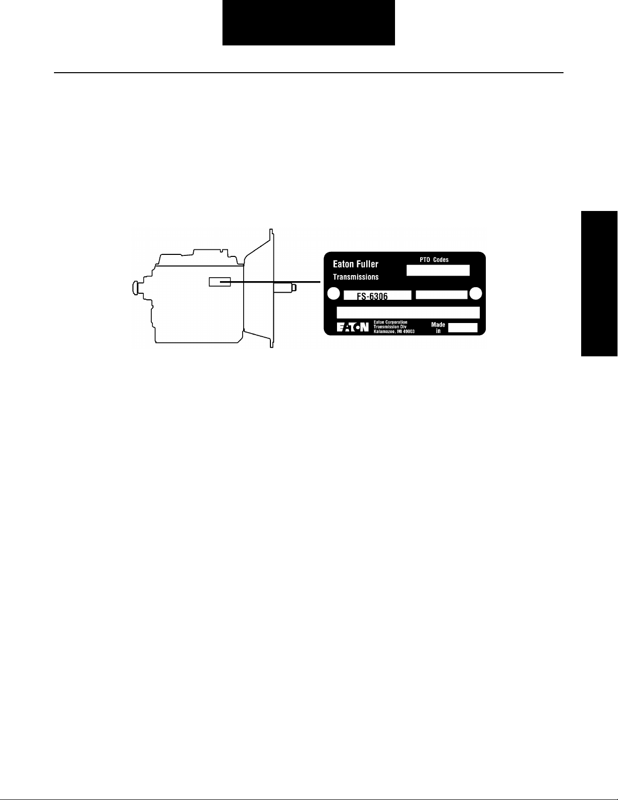
Serial Tag Information and Model Nomenclature
Transmission model designation and other transmission identification information are stamped on the transmission tag. To
identify the transmission model designation and serial number, locate the tag on the transmission and then locate the
numbers as shown.
Transmission Tag and Location
When calling for service assistance or parts, have the model
and serial numbers handy.
Do not remove or destroy the transmission identification
tag.
5
Page 11
Model Information
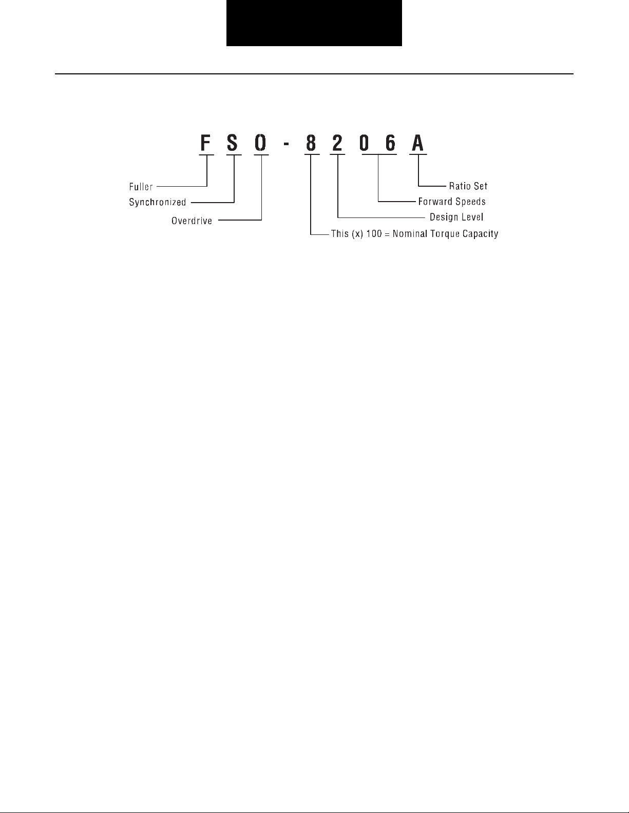
Model Number
The model number gives basic information about the transmission and is explained below. Use this number when calling
for service assistance or replacement parts.
Serial Number
The serial number is the sequential identification number of
the transmission. Before calling for service assistance, write
the number down. It may be needed.
Bill of Material or Customer Number
This number is also referred to as the "TA#" and is located
below the model and serial numbers. It is a reference number
used by Eaton® and is helpful if calling for technical support.
6
Page 12

Specifications
Specifications
Torque Ratings
Correct torque application is extremely important to assure
long transmission life and dependable performance. Overtightening or under-tightening can result in a loose installation
and, in many instances, eventually cause damage to transmission gears, shafts or bearings. Use of a thread sealer/locking
compound is recommended for all capscrews. Do not torque
capscrews dry.
TORQUE CHART
Description
6 Front Bearing Cover Capscrews 15-20 lbs. ft. 5/16-18 Apply Loctite 262 to threads.
4 Shift Lever Housing Capscrews 20-25 lbs. ft. 3/8-16 Apply Loctite 262 to threads.
4 Shift Lever Housing Capscrews for FSO-8406 30-40 lbs. ft. 3/8-16 Apply Loctite 262 to threads.
9 Shift Rail Retainer Capscrews 20-25 lbs. ft. 3/8-16 Apply Loctite 262 to threads.
17 Shift Bar Housing Capscrews 35-40 lbs. ft. 3/8-16 Apply Loctite 262 to threads.
1 Output Shaft Nut, Part Number 21937 300-350 lbs. ft. 1 1/4-18 With nylon locking insert.
1 Output Shaft Nut, Part Number 4304690 500 lbs. ft. +/- 25 1 1/4-18 With nylon locking insert.
4 Clutch Housing Nuts 145-155 lbs. ft. 5/8-16 Apply Loctite 262 to threads.
4 Clutch Housing Nuts for FS-4205 123-137 lbs. ft. 5/8-16 Apply Loctite 262 to threads.
2 Hand Hole Cover Capscrews 5-8 lbs. ft. 1/4-12 Apply Loctite 262 to threads.
4 Mainshaft Rear Bearing Cover Capscrews 60-70 lbs. ft. 1/2-32 Apply Loctite 262 to threads.
1 Oil Fill Plug 25-35 lbs. ft. 3/4" Pipe
1 Oil Drain Plug 45-55 lbs. ft. 3/4" Pipe
Torque Value
lbs. ft.
Thread Size Additional Comments
Oiled at vehicle installation.
Oiled at vehicle installation.
4 Countershaft Rear Bearing Cover Capscrews 35-40 lbs. ft. 3/8"-16 Use plain flat washers.
12 PTO Cover Capscrews 10-20 lbs. ft. 3/8" - 16 Apply Loctite 262 to threads.
Apply Loctite 262 to threads.
7
Page 13

Specifications
8
Page 14
Lubrication Information
Lubrication
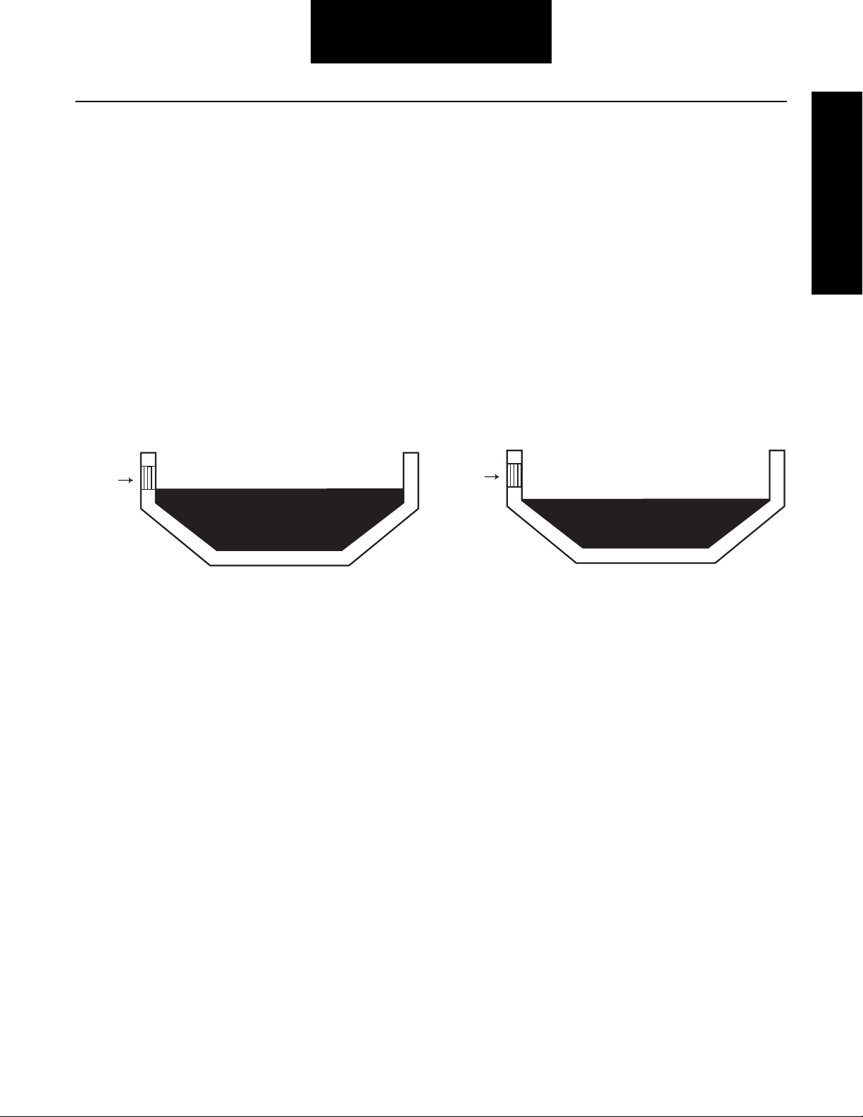
Improper Oil Level
Hole
Proper Oil Level
Hole
Lubrication Information
Proper lubrication procedures are the key to a good all-around
maintenance program.
Eaton® Fuller® Transmissions are designed so that the internal parts operate in an oil circulating bath created by the
motion of the gears and shafts.
All parts will be properly lubricated if these procedures are
closely followed:
1. Maintain oil level. Inspect regularly.
2. Follow maintenance interval chart.
Oil Level
3. Use the correct grade and type of oil.
4. Buy from a reputable dealer.
Maintain Proper Oil Level
Make sure oil is level with the filler opening. Being able to
reach oil with your finger does not mean oil is at proper level.
(One inch of oil level is about one gallon of oil.)
When adding oil, never mix engine oils and gear oils in the
9
Page 15

Lubrication Information
Maintenance Interval Chart
Eaton® Roadranger® CD50 Transmission Fluid
HIGHWAY USE-Heavy Duty and Mid-Range
Initial Fill with Eaton® Roadranger® CD50 Transmission Fluid
Every 10,000 miles Check fluid level. Check for leaks.
Every 250,000 miles Change transmission fluid.
OFF-HIGHWAY USE
Every 40 hours Inspect lubricant level. Check for leaks.
Every 1,000 hours Change transmission fluid where severe dirt conditions exist.
Every 2,000 hours Change transmission fluid. (Normal off-highway use.)
HIGHWAY USE-Heavy Duty and Mid-Range
Initial Fill with Other Recommended Oil
First 3,000 to 5,000 miles Factory fill initial drain. Refill with Eaton® Roadranger® CD50
Transmission Fluid; thereafter follow maintenance intervals above.
Heavy Duty Engine Lubricant
HIGHWAY USE
First 3,000 to 5,000 miles Factory fill initial drain.
Every 10,000 miles Inspect lubricant level. Check for leaks.
Every 50,000 miles Change transmission lubricant.
OFF-HIGHWAY USE
Every 30 hours Change transmission lubricant on new units.
Every 40 hours Inspect lubricant level. Check for leaks.
Every 500 hours Change transmission lubricant where severe dirt conditions exist.
Every 1,000 hours Change transmission lubricant (Normal off-highway use.)
If your vehicle has a transmission oil filter, you must
change the filter when fluid or lubricant is changed.
10
Page 16
Lubrication Information
Lubrication Information
Required Lubricant Chart
Type Grade (SAE) Fahrenheit Ambient Temperature
Eaton® Approved Synthetic
Transmission Oil
Heavy Duty Engine Oil MIL-L-2104D,
API-CD, or Cat TO-4
Additives and friction modifiers must not be introduced.
Never mix engine oils & gear oils in the same transmission.
The use of lubricants not meeting these requirements will
affect warranty coverage.
For a list of Eaton Approved Synthetic Lubricants, call
1-800-826-HELP (4357).
Buy from a reputable dealer
For a complete list of approved and reputable dealers, write
to:
Eaton Corporation
Worldwide Marketing Services
P.O. Box 4013
Kalamazoo, MI 49003
50 All
50 Above 10° F (-12° C)
40 Above 10° F (-12° C)
30 Below 10° F (-12° C)
Transmission Operating Angles
If the transmission operating angle is more than 12 degrees,
improper lubrication will occur. The operating angle is the
transmission mounting angle in the chassis plus the percent
of upgrade (expressed in degrees).
LUBE LEVELS
Model Fill Limit
FS-4005 9.5 pints
FS-5005 10.5 pints
FS-42/5205 11.5 pints
FS-62/6305 19 pints
FS-53/6306 18 pints
FS-5406 18 pints
FS/FSO-6406 19.5 pints
FSO-8406 19.5 pints
11
Page 17

Lubrication Information
12
Page 18

Tool Information
Recommended Tools
Tool Information
Some repair procedures pictured in this manual show the use
of specialized tools. Their actual use is recommended as they
make transmission repair easier, faster, and prevent costly
damage to critical parts.
But for the most part, ordinary mechanic's tools such as
socket wrenches, screwdrivers, etc., and other standard shop
items such as a press, mauls and soft bars are all that is
needed to successfully disassemble and reassemble any
Eaton Fuller Transmission.
SPECIAL TOOLS
REFERENCE
NUMBER
T1 Tension Spring Driver Made from Fuller Transmission Print T-11938
T2 Snap Ring Pliers Tool Supplier
T3 Impact Puller (1/2-13 Threaded End) Tool Supplier
T4 Countershaft Support Tools and Bearing Driver Made from Fuller Transmission Print T-22913-C
T5 Bearing Guide Made from Fuller Transmission Print T-18042-110
T6 Oil Seal Driver, Rear Bearing Cover Made from Fuller Transmission Print T-18088-61
TOOL HOW OBTAINED
The specialized tools can be obtained from a tool supplier or
made from tool prints as required by the individual user.
Detailed Eaton Fuller Transmission Tool Prints are available
upon request by writing to:
Eaton Corporation
Truck Components Operations
Technical Service
P.O. Box 4013
Kalamazoo, Michigan 49003
T7 Input Shaft Nut Installer Made from Fuller Transmission Print T-22553-A
T8 Torque Wrench, 1000 lbs. ft. Capacity Tool Supplier
T9 Oil Seal Driver, Front Bearing Cover (push type clutch) Made from Fuller Transmission Print T-18088-67
T10 Oil Seal Driver, Front Bearing Cover (pull type clutch) Made from Fuller Transmission Print T-18088-64
Special Tools Manufacturers
Below are the addresses and phone numbers of the companies that make tools specifically for Eaton® Fuller® transmissions.
G and W Tool Company
1105 E. Louisville
Broken Arrow, OK 74012-5724
800-247-5882
Great Lakes Tool
8530 M-89
Richland, MI 49083
800-877-9618
O.T.C.
655 Eisenhower Dr.
Owatonna, MN 55060-1171
800-533-6127
The specialized tools can be obtained from a tool supplier or
made from tool prints as required by the individual user.
Detailed Eaton Fuller Transmission Tool Prints are available
upon request by writing to:
Eaton Corporation
Truck Components Operations
Technical Service
P.O. Box 4013
Kalamazoo, Michigan 49003
13
Page 19

Tool Information
14
Page 20

Preventive Maintenance
Preventive Maintenance
Preventive Maintenance
Everyday there are countless vehicles operating over the highways with transmissions in such a neglected mechanical condition, they can be referred to as failures looking for a place to
break down. They lack a proper and organized preventive
maintenance program.
Preventive maintenance is a general term which applies to all
procedures necessary to have maximum life and satisfactory
service at the lowest possible cost, short of removing and
repairing the unit.
Checks Before Transmission Removal
A number of conditions contrary to good preventive maintenance can generally be pointed to when inspecting a failed
transmission. Taking a few minutes every so many hours or
miles to do a few simple checks could help avoid eventual
breakdown or reduce the repair cost. If the transmission is
not cared for, it will breakdown.
Transmission appearance may differ, however the procedure
is the same.
Note: Transmission appearance may differ, the procedure is
the same.
Clutch Housing Mounting (1)
• Check all capscrews of clutch housing flange for
looseness.
Clutch Release Bearing (Not Shown)
• Remove hand hole cover and check radial and axial
clearance in release bearing.
• Check relative position of thrust surface of release
bearing with thrust sleeve on push-type clutches.
Clutch Pedal Shaft and Bores (3)
• Pry upward on shafts to check wear.
• If excessive movement is found, remove clutch
release mechanism and check bushings on bores
and wear on shafts. See OEM literature.
Lubricant (4)
• Change at specified service intervals.
• Use only the types and grades as recommended. See
"Recommended Lubrication Chart".
15
Page 21

Preventive Maintenance
Filler and Drain Plugs (5)
• Remove filler plugs and check level of lubricant at
specified intervals. Tighten fill and drain plugs
securely.
Capscrews and Gaskets (6)
• Check all capscrews, especially those on PTO covers
and rear bearing covers for looseness which would
cause oil leakage.
• Check PTO opening and rear bearing covers for oil
leakage due to faulty gasket.
Gear Shift Lever (7)
• Check for looseness and free play in housing. If lever
is loose in housing, check Gear Shift Lever Housing
Assembly.
Gear Shift Lever Housing Assembly (8)
• Remove the gear shift lever housing assembly from
the transmission.
• Check the tension spring and washer for set and
wear.
• Check gear shift lever bottom end for wear in the
slots and check for wear of finger assembly and
housing.
Checks With Drive Line Dropped
Universal Joint Companion Flange or Yoke Nut (9)
• Check for tightness. Tighten to recommended
torque.
Output Shaft (Yoke Nut Tightened)
• Pry upward against output shaft to check radial
clearance in mainshaft rear bearing.
Checks With Universal Joint Companion Flange or Yoke Removed
Note: If necessary, use solvent and shop rag to clean sealing
surface of companion flange or yoke. Do not use crocus
cloth, emery paper, or other abrasive materials that will
mar surface finish.
Splines on Output Shaft (11)
• Check for wear from movement and chucking action
of the universal joint companion flange or yoke.
Mainshaft Rear Bearing Cover (12)
• Check oil seal for wear.
16
Page 22

Preventive Maintenance
Preventive Maintenance
Inspection
Part to Inspect What to Check For Action to be Done
Speedometer Connections Speedometer cables should not be
loose.
Should be an O-ring or gasket between
the mating speedometer sleeve and the
rear bearing cover.
Rear Bearing Cover Nuts Check retaining nuts for tightness. Apply Eaton Sealant #71225 to the capscrew threads.
Output Yoke Retaining Nut Check the output yoke retaining nut for
tightness.
PTO Covers and Openings Check the capscrews for tightness. Apply Eaton Sealant #71225 to the capscrew threads,
Front Bearing Cover Check front bearing cover, front case,
shift bar housing, rear bearing cover,
and clutch housing for cracks or breaks.
Check the capscrews for tightness. Tighten the capscrews to 15-25 lbs. ft.
Oil Drain Plug, Oil Fill Plug Check the oil drain plug and the oil fill
plug for leakage.
Applied hydraulic thread sealant #71208 to threads.
Torque speedometer sleeve to 35-50 lbs. ft.
Replace the O-ring/gasket if damaged or missing.
Torque capscrews to 60-70 lbs. ft.
Torque the output yoke retaining nut to 300-350 lbs.
ft. (For FS-6106 series: 235-275 lbs. ft.) Do not over
torque the output nut.
if not precoated. Tighten PTO capscrews to 10-20 lbs.
ft.
Replace parts found to be damaged.
Torque the oil drain plug to 45-55 lbs. ft.
Torque the oil fill plug to 25-35 lbs. ft.
Rear Seal Maintenance
Leakage in transmission rear seals is perhaps the most common problem in truck transmissions. The problem is more
than a nuisance because if not repaired, a leaking seal can
lead to catastrophic transmission failure. There have been
strides in reducing leakage through improved designs and the
use of new seal materials. However, the most important way
to reduce this problem continues to be through proper service
and installation procedures.
It can be very time consuming and expensive to replace a rear
seal system, then find the oil seal system was not causing the
oil leakage. Using the following checklist, inspect the transmission to insure proper identification of the leak path.
Before disassembling the rear seal system, clean the rear
bearing cover, the rear seal, and the output yoke. DO NOT
USE A HIGH PRESSURE SPRAY WASHER TO CLEAN THE
REAR SEAL SYSTEM. USE A CLEAN DRY CLOTH. Run the
vehicle, then inspect these areas for oil leaks.
For more detailed information on rear seal maintenance, order
TCSM-0912, "Seal Maintenance Guide." To receive a Product
Literature Order Form, write to:
Eaton Corporation
Global Marketing Services
P.O. Box 4013
Kalamazoo, MI 49003
17
Page 23

Preventive Maintenance
18
Page 24
Power Flow
Power Flow
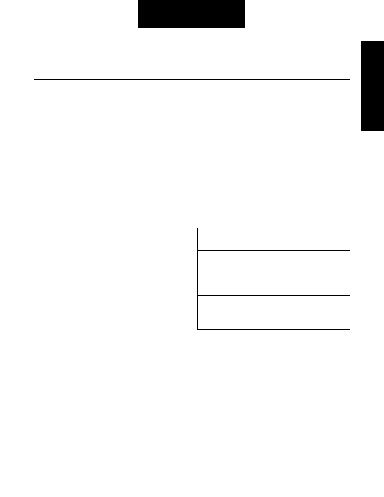
Power Flow
The transmission must efficiently transfer the engine's power,
in terms of torque, to the vehicle's rear wheels. Knowledge of
what takes place in the transmission during torque transfer is
essential when trouble-shooting and when making repairs
become necessary.
1. Power (torque) from the engine is transferred to the
transmission input shaft.
2. Torque is transferred to countershaft drive gear.
FS-5205 First Gear
3. Torque is delivered along countershaft to all countershaft gears.
4. Torque is transferred to "engaged" mainshaft gear.
The cross section view illustrates 1st speed gear
position.
5. The engaged mainshaft gear external clutching teeth
transfer torque to the mainshaft through the synchronizer assembly or sliding clutch.
6. The mainshaft transfers torque directly to driveshaft
through the output yoke.
19
Page 25
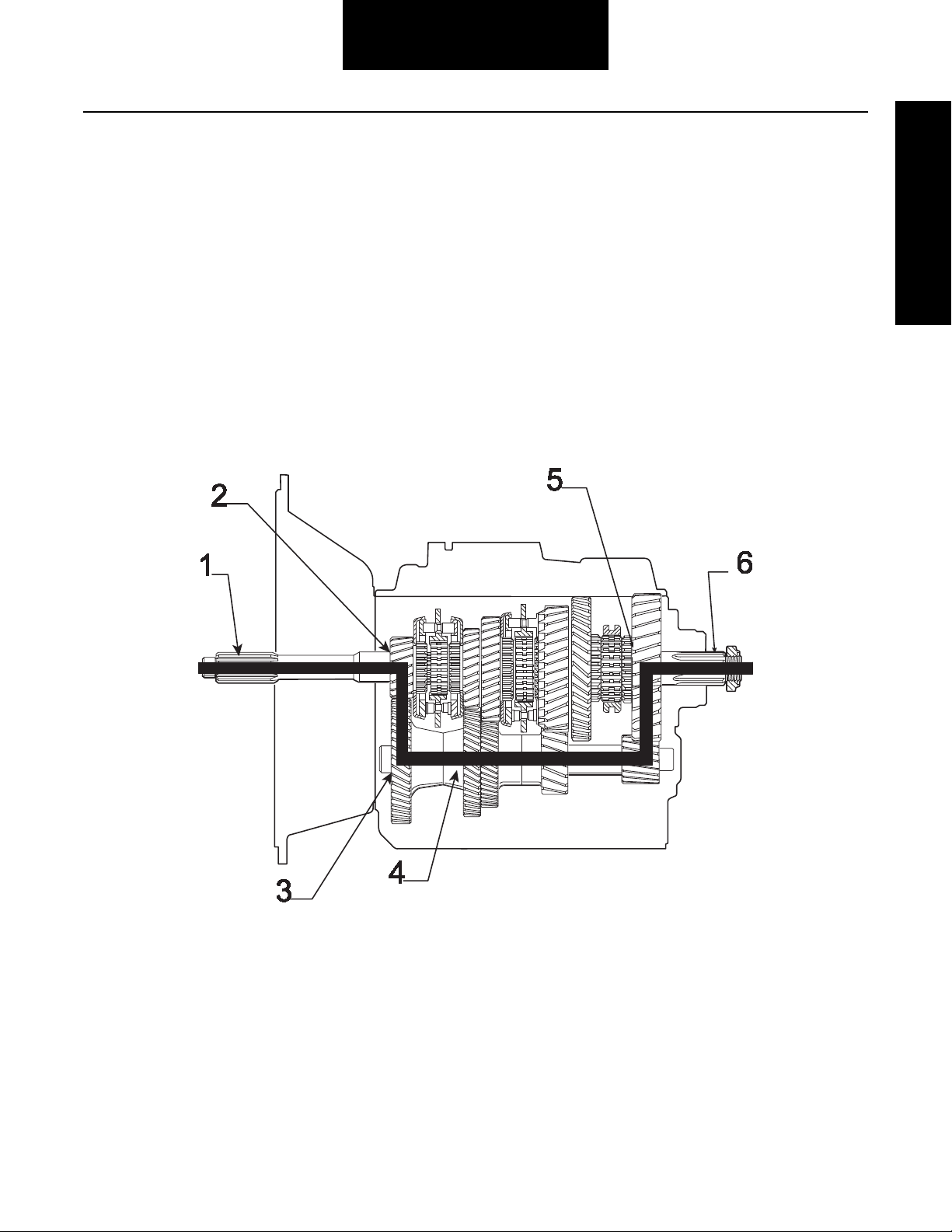
FS-5205 Second Gear
Power Flow
FS-5205 Third Gear
20
Page 26
Power Flow
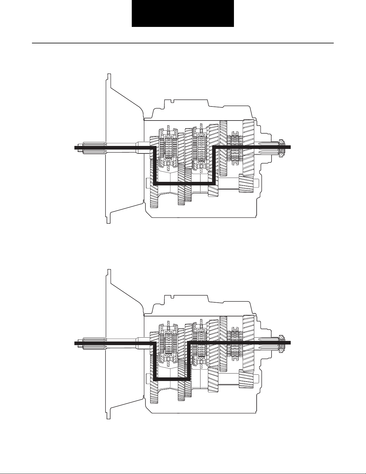
FS-5205 Fourth Gear
Power Flow
FS-5205 Fifth Gear or Direct
21
Page 27

Power Flow
22
Page 28

In-Vehicle Service Procedures
Shift Bar Housing
How to Remove the Gear Shift Lever
Special Instructions
Remote control housings are removed the same way as gear shift levers.
Procedure -
1. From the gear shift lever base, remove the four (4) retaining capscrews.
2. To break the gasket seal, lightly jar the gear shift housing.
3. Remove the gear shift lever housing.
4. Remove the gasket and clean all mounting surfaces of
gasket material.
23
Page 29

In-Vehicle Service Procedures
How to Install the Gear Shift Lever
Special Instructions
Remote control housings are installed the same way as gear shift levers.
Make sure the shift block and yoke notches are aligned in the neutral position.
Procedure -
1. Position a new gear shift lever gasket on the gear shift
lever mounting surface.
2. Fit the gear shift lever into the shift block.
3. Apply Eaton/Fuller Sealant #71225 or equivalent to the
retaining capscrews, if not precoated.
4. Install the retaining capscrews, tighten to 20-25 lbs. ft. of
torque.
Final Check
Make sure the capscrews are properly torqued.
Make sure you can shift the transmission.
24
Page 30

In-Vehicle Service Procedures
Shift Bar Housing
How to Remove the Shift Bar Housing
Special Instructions
There are two (2) lengths of capscrews. The 1 1/2" capscrews are used with the lifting eyes. Note their location.
Shift transmission into neutral position.
Procedure -
1. From the shift bar housing rim, remove the retaining capscrews.
2. To break the gasket seal, jar the shift bar housing.
3. Remove the shift bar housing.
4. Remove the gasket and clean all mounting surfaces of
gasket material.
25
Page 31

In-Vehicle Service Procedures
How to Install the Shift Bar Housing
Special Instructions
There are two (2) lengths of capscrews. The 1 1/2" capscrews are used with the lifting eyes.
Apply Eaton/Fuller gasket sealant #71233 or equivalent to shift bar housing gasket before assembly.
Procedure -
1. Place the shift bars in the neutral position.
2. Place the synchronizers in the neutral position.
3. Position a new shift bar housing gasket on the shift bar
housing mounting surface.
4. As you install the shift bar housing, make sure the yokes
fit onto the corresponding synchronizers.
6. Install the center rear retaining capscrew first and the
center front retaining capscrew second, tighten to 35-40
lbs. ft. of torque.
7. Install the remaining capscrews, tighten to 35-40 lbs. ft.
of torque.
5. Apply Eaton/Fuller sealant #71225 or equivalent to the
retaining capscrews, if not precoated.
26
Final Check
Make sure the capscrews are properly torqued.
Page 32

In-Vehicle Service Procedures
Output Yoke
How to Remove the Output Yoke/Companion Flange
Special Instructions
You must remove the shift bar housing in order to lock the transmission.
Special Tools
A large breaker bar or air impact wrench
Procedure -
1. Engage two (2) mainshaft synchronizers into two (2)
mainshaft gears to lock the transmission.
2. Use a breaker bar to remove the nut from the output
shaft.
3. Pull the output yoke or flange straight to the rear and off
the output shaft.
27
Page 33

In-Vehicle Service Procedures
How to Install the Output Yoke/Companion Flange
Special Instructions
You must remove the shift bar housing in order to lock the transmission.
Special Tools
Torque wrench with 500 lbs. ft. capacity
Procedure -
1. Engage two (2) mainshaft synchronizers into two (2)
mainshaft gears to lock the transmission.
2. Install the speedometer drive gear rotor or replacement
spacer on the output shaft inside the rear bearing cover.
3. Slide the companion flange or yoke onto the output
shaft.
Final Check
Make sure the output shaft nut is properly torqued.
Unlock the transmission.
4. Install the output shaft nut, tighten to 300-350 lbs. ft. of
torque.
28
Page 34

In-Vehicle Service Procedures
Clutch Housing
How to Remove the Clutch Housing
Special Instructions
Removal of the clutch housing is done in the horizontal position.
Procedure -
1. Remove the four clutch housing retaining bolts from the
case and clutch housing.
2. Jar clutch housing with a rubber mallet and pull the
clutch housing from transmission case.
29
Page 35

In-Vehicle Service Procedures
How to Install the Clutch Housing
Procedure -
1. Position clutch housing on front of transmission.
2. Install four retaining bolts and torque to the recommended torque.
30
Page 36

Transmission Overhaul
Shift Bar Housing
Procedures-Bench Service
Functions of a Shift Bar Housing
Shift bar housings are a very important part of the transmission. No matter what kind of shift bar housing your transmission has, they all provide the same functions:
• Engage the transmission gearing,
• Prevents the driver from shifting into 2 gears at the
same time,
• Prevents shifting into reverse without force,
• Actuates the back up lights,
• Actuates the neutral switches.
31
Page 37

Transmission Overhaul
Procedures-Bench Service
How to Disassemble the Gear Shift Lever
Special Instructions
For safety reasons when disassembling the gear shift lever, release the spring one coil at a time.
WARNING: Wear safety glasses when removing spring.
Special Tools
Vise with brass jaws or wood blocks
Procedure -
1. Remove the shift lever boot.
2. Slide the boot up the shift lever shaft and remove.
3. With housing bottom facing up, secure the assembly in a
vise.
4. Use large screwdriver to twist between the spring and
housing, forcing the spring from under the housing lugs.
5. From inside the housing tower, remove the tension
spring, washer, and gear shift lever.
6. From the housing tower remove spade pin bores, and
inspect the spade pins, discard if damaged.
32
7. If housing tower spade pin bores are worn, discard the
housing tower and replace with a new housing tower.
Page 38

Transmission Overhaul
Shift Bar Housing
Procedures-Bench Service
How to Assemble the Gear Shift Lever
Special Instructions
Inspect tension spring, washer, and pivot pin bores for wear. (Replace, if oblong.)
Apply oil to the shift lever pivot ball and housing socket prior to assembly.
Seat the tension spring one coil at a time.
Special Tools
See Recommended Tools on page 13.
Vise with brass jaws or wood blocks
Item T1: Tension spring driver
Procedure -
1. With housing bottom facing up, secure the assembly in a
vise.
2. If housing tower pivot pin bores are worn, discard the
housing tower and replace with a new housing tower.
3. If the pivot pins are damaged, replace and install the pivot
pins in housing tower bore.
4. Align the lever ball slot with the pivot pin and position the
gear shift lever in the housing tower.
6. Use a tension spring driver to install the tension spring
under the housing lugs.
7. Remove the assembly from the vise.
8. Install a rubber boot over the gear shift lever and against
the housing.
5. With dished-side up, install the washer over the ball.
9. Install the shift lever grip.
Final Check
Make sure the gear shift lever can move.
33
Page 39

Transmission Overhaul
Procedures-Bench Service
How to Disassemble the FS-4205 Shift Bar Housing
Special Instructions
The shift bar housing must be removed from the transmission.
During disassembly, lay all parts on a clean bench in order of removal to facilitate assembly.
Shift bars not being removed must be kept in the neutral position or the interlocking parts lock the bars.
Start with 1st-reverse yoke assembly.
When removing the interlock balls, detent balls, and springs, remove the interlock and detent balls before removing the springs.
Procedure -
1. Lay shift bar housing on work bench. Shift 4th-5th yoke
assembly into 4th speed position. Remove capscrews
and retainers.
2. Remove 1st-reverse yoke assembly.
4. Remove 4th-5th yoke assembly. If the yoke pad bushings
are to be replaced, remove worn pad from shift yoke,
install new pad and bend tabs over top and bottom of
yoke.
Note: If yoke replacement is required, yoke can be
removed by driving the roll pin through the yoke
and rail with a punch and hammer.
Note: Install new yoke by aligning shift yoke with shift
bar alignment hole and insert lock pin.
5. Remove interlock balls, detent balls, and springs.
3. Remove 2nd-3rd yoke assembly and interlock pin.
34
Page 40

Transmission Overhaul
Shift Bar Housing
Procedures-Bench Service
How to Assemble the FS-4205 Shift Bar Housing
Special Instructions
Interlock balls, detent balls, and springs can be used interchangeably.
Lubricate yoke pads and inserts with oil before assembly.
Lubricate yoke bar grooves with grease before assembly.
Keep yoke bars in neutral while assembling.
The shift yoke retainer holes are not tapped on new shift bar housings. The capscrews that are used are "thread forming" and can
be reused if the shift bar housing is replaced.
It may be necessary to support the yoke bars in position while installing the retainers.
Procedure -
1. Install interlock balls, detent balls and springs in the following sequence;
A. Position (3) balls in the reverse light switch bore.
B. Install 1st-reverse detent spring and ball.
C. Position (2) balls in adjacent cross bore.
D. Install 2nd-3rd detent spring and ball.
E. Position (2) balls in adjacent cross bore
F. Install 4th-5th detent spring and ball.
Note: Balls and springs can be used interchangeably.
2. Position 1st-reverse yoke in housing assembly as shown.
3. Install interlock pin in 2nd-3rd yoke assembly and position as shown.
4. Position 4th-5th yoke assembly in housing as shown.
35
Page 41

Transmission Overhaul
Procedures-Bench Service
5. Position shift yokes as shown. Install front and rear
retainer over shift rails and install front two capscrews.
Tighten all rail support capscrews to 20-25 lbs. ft. (27-34
N•m).
Note: It may be necessary to support rails in proper posi-
tion while installing rail supports.
36
Page 42

Transmission Overhaul
Shift Bar Housing
Procedures-Bench Service
How to Disassemble the FS-5205 Shift Bar Housing
Special Instructions
The shift bar housing must be removed from the transmission.
During disassembly, lay all parts on a clean bench in order of removal to facilitate assembly.
Shift bars not being removed must be kept in the neutral position or the interlocking parts lock the bars.
Start with 4th-5th yoke assembly.
When removing the interlock balls, detent balls, and springs, remove the interlock and detent balls before removing the springs.
Special Tools
Magnet
Procedure -
1. With the housing rear to the right, lay the assembly on a
flat surface.
2. In order to remove the front retaining capscrews, shift
4th-5th yoke assembly into 4th gear position (rearward).
3. Remove capscrews and retainers.
4. Remove 4th-5th yoke assembly.
5. Remove 2nd-3rd yoke assembly and interlock pin.
6. Remove 1st-reverse bar assembly.
37
Page 43

Transmission Overhaul
Procedures-Bench Service
7. If necessary, remove 1st-reverse bar front spacer.
8. From the 1st-reverse yoke assembly, remove the 1streverse lock pin.
9. Remove the 1st-reverse assembly.
12. Inspect the yoke pad bushings. If the pads are worn,
remove worn pad from shift yoke, install new pad and
bend tabs over yoke top and bottom.
13. Inspect the yokes. If the yokes are damaged, remove by
driving the roll pin through the yoke and rail.
10. Remove the 1st-reverse actuator.
11. Remove the four (4) interlock balls, the three (3) detent
balls, the three (3) back up light switch balls, and the
three (3) springs.
38
Page 44

Transmission Overhaul
Shift Bar Housing
Procedures-Bench Service
How to Assemble the FS-5205 Shift Bar Housing
Special Instructions
Interlock balls, detent balls, and springs can be used interchangeably.
Lubricate yoke pads and inserts with oil before assembly.
Lubricate yoke bar grooves with grease before assembly.
Keep yoke bars in neutral while assembling.
The shift yoke retainer holes are not tapped on new shift bar housings. The capscrews that are used are "thread forming" and can
be reused if the shift bar housing is replaced.
It may be necessary to support the yoke bars in position while installing the retainers.
Procedure -
1. Install interlock balls, detent balls and springs in the following sequence;
A. Position (3) balls in the reverse light switch bore.
B. Install 1st-reverse detent spring and ball.
C. Position (2) balls in adjacent cross bore.
D. Install 2nd-3rd detent spring and ball.
E. Position (2) balls in adjacent cross bore
F. Install 4th-5th detent spring and ball.
Note: Balls and springs can be used interchangeably.
2. Over the actuator pivot pin, seat the 1st reverse actuator.
3. Position 1st-reverse yoke in housing assembly as shown.
4. Install the 1st-reverse lock pin in the yoke assembly.
5. Position 1st-reverse bar assembly in the housing.
6. Install interlock pin in 2nd-3rd yoke assembly and position as shown.
7. Position 4th-5th yoke assembly in housing as shown.
39
Page 45

Transmission Overhaul
Procedures-Bench Service
8. Position retainers, front retainer in rear set of holes.
9. Install the capscrews in rear retainer. Tighten all rail support capscrews to 20-25 lbs. ft. (27-34 N•m).
Note: It may be necessary to support rails in proper posi-
tion while installing rail supports.
10. Carefully shift the 4th-5th yoke into 4th gear position
(rearward).
11. Install the capscrews in front retainer. Tighten all rail support capscrews to 20-25 lbs. ft. (27-34 N•m).
40
Page 46

Transmission Overhaul
Shift Bar Housing
Procedures-Bench Service
How to Disassemble the FS-6205/6305 Shift Bar Housing
Special Instructions
The shift bar housing must be removed from the transmission.
During disassembly, lay all parts on a clean bench in order of removal to facilitate assembly.
Shift bars not being removed must be kept in the neutral position or the interlocking parts lock the bars.
Start with 1st-reverse yoke assembly.
When removing the interlock balls, detent balls, and springs, remove the interlock and detent balls before removing the springs.
Procedure -
1. With the housing rear to the right, lay the assembly on a
flat surface.
2. In order to remove the front retaining capscrews, shift
4th-5th yoke assembly into 4th gear position (rearward).
3. Remove capscrews and retainers.
4. Remove 1st-reverse yoke assembly.
6. Remove 4th-5th yoke assembly.
7. Inspect the yoke pad bushings. If the pads are worn,
remove worn pad from shift yoke, install new pad and
bend tabs over yoke top and bottom.
8. Inspect the yokes. If the yokes are damaged, remove by
driving the roll pin through the yoke and rail.
9. Remove the interlock balls, detent balls, and springs.
5. Remove 2nd-3rd yoke assembly and interlock pin.
41
Page 47

Transmission Overhaul
Procedures-Bench Service
How to Assemble the FS-6205/6305 Shift Bar Housing
Special Instructions
Interlock balls, detent balls, and springs can be used interchangeably.
Lubricate yoke pads and inserts with oil before assembly.
Lubricate yoke bar grooves with grease before assembly.
Keep yoke bars in neutral while assembling.
The shift yoke retainer holes are not tapped on new shift bar housings. The capscrews that are used are "thread forming" and can
be reused if the shift bar housing is replaced.
It may be necessary to support the yoke bars in position while installing the retainers.
Procedure -
1. Install interlock balls, detent balls and springs in the following sequence;
A. Position (3) balls in the reverse light switch bore.
B. Install 1st-reverse detent spring and ball.
C. Position (2) balls in adjacent cross bore.
D. Install 2nd-3rd detent spring and ball.
E. Position (2) balls in adjacent cross bore
F. Install 4th-5th detent spring and ball.
Note: Balls and springs can be used interchangeably.
2. Position 1st-reverse yoke in housing assembly as shown.
3. Install the interlock pin in 2nd-3rd yoke assembly.
4. Position 2nd-3rd yoke in housing assembly.
5. Position 4th-5th yoke in housing assembly.
6. Position retainers, front retainer in rear set of holes.
42
Page 48

Transmission Overhaul
Shift Bar Housing
Procedures-Bench Service
7. Install the capscrews in the middle and rear retainer.
Tighten all rail support capscrews to 20-25 lbs. ft. (27-34
N•m).
Note: It may be necessary to support rails in proper posi-
tion while installing rail supports.
8. Carefully shift the 4th-5th yoke into 4th gear position
(rearward).
9. Install the capscrews in front retainer. Tighten all rail support capscrews to 20-25 lbs. ft. (27-34 N•m).
Final Check
Make sure interlocking system is working - can't shift into 2
gears at the same time.
43
Page 49

Transmission Overhaul
Procedures-Bench Service
How to Disassemble the FS-5306/6306/5406/6406 Shift Bar Housing
Special Instructions
The shift bar housing must be removed from the transmission.
During disassembly, lay all parts on a clean bench in order of removal to facilitate assembly.
Shift bars not being removed must be kept in the neutral position or the interlocking parts lock the bars.
Start with reverse yoke assembly.
When removing the interlock balls, detent balls, and springs, remove the interlock and detent balls before removing the springs.
Procedure -
1. With the housing rear to the right, lay the assembly on a
flat surface.
2. In order to remove the front retaining capscrews, shift
5th-6th yoke assembly into 5th gear position (rearward).
3. Remove capscrews and retainers.
4. Remove reverse yoke assembly.
6. Remove 3rd-4th yoke assembly and interlock pin.
7. Remove 5th-6th yoke assembly.
8. Inspect the yoke pad bushings. If the pads are worn,
remove worn pad from shift yoke, install new pad and
bend tabs over yoke top and bottom.
5. Remove 1st-2nd yoke assembly and interlock pin.
44
Page 50

Transmission Overhaul
Shift Bar Housing
Procedures-Bench Service
9. Inspect the yokes. If the yokes are damaged, remove by
driving the roll pin through the yoke and rail.
10. Remove the interlock balls, detent balls, and springs.
45
Page 51

Transmission Overhaul
Procedures-Bench Service
How to Assemble the FS-5306/6306/5406/6406 Shift Bar Housing
Special Instructions
Interlock balls, detent balls, and springs can be used interchangeably.
Lubricate yoke pads and inserts with oil before assembly.
Lubricate yoke bar grooves with grease before assembly.
Keep yoke bars in neutral while assembling.
The shift yoke retainer holes are not tapped on new shift bar housings. The capscrews that are used are "thread forming" and can
be reused if the shift bar housing is replaced.
It may be necessary to support the yoke bars in position while installing the retainers.
Procedure -
1. Install interlock balls, detent balls and springs in the following sequence;
A. Position (3) balls in the reverse light switch bore.
B. Install reverse detent spring and ball.
C. Position (2) balls in adjacent cross bore.
D. Repeat steps B and C for 1st-2nd position, 3rd-4th
position, and 5th-6th position.
Note: Balls and springs can be used interchangeably.
2. Position reverse yoke in housing assembly as shown.
4. Position 1st-2nd yoke in housing assembly.
5. Install the interlock pin in 3rd-4th yoke assembly.
6. Position 3rd-4th yoke in housing assembly.
7. Position 5th-6th shift block in housing assembly.
3. Install the interlock pin in 1st-2nd yoke assembly.
46
Page 52

Transmission Overhaul
Shift Bar Housing
Procedures-Bench Service
8. Position retainers, front retainer in rear set of holes.
9. Install the capscrews in the middle and rear retainers.
Tighten all rail support capscrews to 20-25 lbs. ft. (27-34
N•m).
Note: It may be necessary to support rails in proper posi-
tion while installing rail supports.
10. Carefully shift the 5th-6th yoke into 5th gear position
(rearward).
11. Install the capscrews in front retainer. Tighten all rail support capscrews to 20-25 lbs. ft. (27-34 N•m).
Final Check
Make sure interlocking system is working - can't shift into 2
gears at the same time.
47
Page 53

Transmission Overhaul
Procedures-Bench Service
How to Disassemble the FSO-6406/8406 Shift Bar Housing
Special Instructions
The shift bar housing must be removed from the transmission.
During disassembly, lay all parts on a clean bench in order of removal to facilitate assembly.
Shift bars not being removed must be kept in the neutral position or the interlocking parts lock the bars.
Start with 5th-6th yoke assembly.
When removing the interlock balls, detent balls, and springs, remove the interlock and detent balls before removing the springs.
Procedure -
1. With the housing rear to the right, lay the assembly on a
flat surface.
2. Remove capscrews and retainers.
3. Remove 5th-6th yoke assembly.
4. Remove 5th-6th shift block.
6. Remove 1st-2nd yoke assembly and interlock pin.
7. Remove reverse yoke assembly.
8. Inspect the yoke pad bushings. If the pads are worn,
remove worn pad from shift yoke, install new pad and
bend tabs over yoke top and bottom.
5. Remove 3rd-4th yoke assembly and interlock pin.
48
Page 54

Transmission Overhaul
Shift Bar Housing
Procedures-Bench Service
9. Inspect the yokes. If the yokes are damaged, remove by
driving the roll pin through the yoke and rail.
10. Remove the interlock balls, detent balls, and springs.
49
Page 55

Transmission Overhaul
Procedures-Bench Service
How to Assemble the FSO-6406/8406 Shift Bar Housing
Special Instructions
Interlock balls, detent balls, and springs can be used interchangeably.
Lubricate yoke pads and inserts with oil before assembly.
Lubricate yoke bar grooves with grease before assembly.
Keep yoke bars in neutral while assembling.
The shift yoke retainer holes are not tapped on new shift bar housings. The capscrews that are used are "thread forming" and can
be reused if the shift bar housing is replaced.
It may be necessary to support the yoke bars in position while installing the retainers.
Procedure -
1. Install interlock balls, detent balls and springs in the following sequence;
A. Position (3) balls in the reverse light switch bore.
B. Install reverse detent spring and ball.
C. Position (2) balls in adjacent cross bore.
D. Repeat steps B and C for 1st-2nd position, 3rd-4th
position, and 5th-6th position.
Note: Balls and springs can be used interchangeably.
2. Position reverse yoke in housing assembly as shown.
3. Install the interlock pin in 1st-2nd yoke assembly.
4. Position 1st-2nd yoke in housing assembly.
5. Install the interlock pin in 3rd-4th yoke assembly.
6. Position 3rd-4th yoke in housing assembly.
7. Position 5th-6th shift block in housing assembly.
50
Page 56

Transmission Overhaul
Shift Bar Housing
Procedures-Bench Service
8. Install the middle retainer capscrews.
Note: It may be necessary to support rails in proper posi-
tion while installing retainer.
9. Position 5th-6th yoke in housing assembly.
Note: The 5th-6th yoke is aligned by the dowel pin and
the capscrew hole shown in the picture.
Final Check
Make sure interlocking system is working - can't shift into 2
gears at the same time.
10. Position the last retainer and start the capscrews in the
remaining capscrew holes.
11. Start with the capscrew shown in the picture and tighten
all rail support capscrews to 20-25 lbs. ft. (27-34 N•m).
51
Page 57

Transmission Overhaul
Procedures-Bench Service
How to Disassemble the Reverse Plunger on FS-4X05/5X05
Special Instructions
Retainer is under spring pressure.
Procedure -
1. Remove the reverse plunger retaining plug and gasket.
2. Remove the reverse plunger spring.
3. Remove the reverse plunger stop.
5. Inspect reverse plunger. Replace damaged parts.
4. Remove the reverse plunger.
52
Page 58

Transmission Overhaul
Shift Bar Housing
Procedures-Bench Service
How to Assemble the Reverse Plunger on FS-4X05/5X05
Special Instructions
With the reverse plunger bore up, place the shift bar housing on its side.
Procedure -
1. Install the reverse plunger.
2. Install the reverse plunger spring.
4. Install the reverse plunger gasket and plug.
5. Tighten the plug to 8-12 lbs. ft. (10.8-16.2 N•m) of
torque.
Final Check
Make sure snap ring is securely in shift block groove.
3. Install the reverse plunger stop.
53
Page 59

Transmission Overhaul
Procedures-Bench Service
How to Disassemble the Reverse Plunger For All Models Except FS-4205/5205
Special Instructions
Snap ring and retainer are under spring pressure.
WARNING: Wear safety glasses when removing snap rings.
Procedure -
1. Depress reverse plunger springs and retainer.
2. Remove snap ring and spring retainer.
3. Remove the reverse plunger springs.
4. Remove washer and plunger.
5. Inspect reverse plunger parts. Replace worn or damaged
parts.
54
Page 60

Transmission Overhaul
Shift Bar Housing
Procedures-Bench Service
How to Assemble the Reverse Plunger For All Models Except FS-4205/5205
Special Instructions
Place the reverse yoke bar in a vise.
WARNING: Wear safety glasses when installing snap rings.
Special Tools
Vise with brass jaws or wood blocks
Snap ring pliers
Procedure -
1. Install plunger and washer.
2. Install reverse plunger springs.
3. Depress the reverse plunger retainer and springs.
4. Install the snap ring in the shift block groove.
Final Check
Make sure snap ring is securely in shift block groove.
55
Page 61

Transmission Overhaul
Procedures-Bench Service
56
Page 62

Transmission Overhaul
Disassemble Main Section
Procedures-Bench Service
How to Remove the Input Shaft Assembly
Special Instructions
WARNING: Wear safety glasses when using a chisel to remove bearing cage.
Procedure -
1. Turn out six capscrews, jar front bearing cover with a
rubber mallet and remove. If necessary remove oil seal
from cover.
2. Remove input shaft assembly from transmission.
3. Using a chisel, remove bearing cage and rollers. Install
bearing puller and remove bearing race from input shaft.
57
Page 63

Transmission Overhaul
Procedures-Bench Service
How to Remove the Mainshaft Assembly
Special Instructions
WARNING: Wear safety glasses when removing snap rings.
Special Tools
Sling and hoist
Procedure -
1. Remove the speedometer sleeve and driven gear.
2. Turn out four retaining nuts and lockwashers.
3. Using screwdrivers in notches, remove rear bearing
cover. If necessary remove oil seal from cover.
5. For the FS-5205 model, tap on the mainshaft front to
move the mainshaft rearward about 1/4". Use pry bars to
remove the rear bearing cup and locating snap ring.
6. Wrap a sling around the 3rd-4th synchronizer assembly.
Use a hoist to remove the mainshaft assembly from the
case.
4. Remove shims and speedometer drive gear or rotor.
Note: Shims may come off with rear bearing cover.
58
Page 64

Transmission Overhaul
Disassemble Main Section
Procedures-Bench Service
How to Remove the Countershaft Assembly
Procedure -
1. Turn out capscrews, remove countershaft rear bearing
cover and shims.
2. Remove the countershaft rear bearing cup.
Note: Countershaft may slide to the rear and out of bear-
ing bore.
4. If countershaft front bearing race is to be replaced, drive
bore plug through front of transmission and drive the
race to the rear toward the inside of the case.
3. Move countershaft assembly to the rear and lift it from
the case.
59
Page 65

Transmission Overhaul
Procedures-Bench Service
How to Remove the Reverse Idler Gear Assembly For All Models Except FS-5306/6306
Special Tools
Rolling wedge bar
Procedure -
1. Remove the reverse idler lock and retaining capscrew.
2. Using a rolling wedge bar, remove reverse idler shaft.
3. Remove reverse idler, bearings, spacer and thrust washers.
60
Page 66

Transmission Overhaul
Disassemble Main Section
Procedures-Bench Service
How to Remove the FS-5306/6306 Reverse Idler Gear Assembly
Special Tools
Sliding hammer
Procedure -
1. Use the slide hammer and remove reverse idler shaft.
2. Remove the locating ball.
3. Remove reverse idler assembly and thrust washers.
4. From the reverse idler assembly, remove the bearings
and spacer.
61
Page 67

Transmission Overhaul
Procedures-Bench Service
62
Page 68

Transmission Overhaul
Mainshaft Assembly
Procedures-Bench Service
How to Disassemble the FS-4205 Mainshaft Assembly
Special Instructions
During disassembly, lay all parts on a clean bench in order of removal to facilitate reassembly.
WARNING: Wear safety glasses when removing snap rings.
Special Tools
Vise with brass jaws or wood blocks
Snap ring pliers
Gear puller
Procedure - See Mainshaft FRONT Facing Up illustration
1. With mainshaft front facing up, install the mainshaft
assembly vertically in a vise.
2. Remove shift hub thrust bearing and bearing race.
3. Remove 4th-5th speed synchronizer and cups.
4. Remove 4th-5th clutch hub.
5. Remove 4th gear and 4th gear bearing.
6. Remove 3rd gear retaining snap ring.
7. Remove 3rd gear thrust washer and locating ball.
8. Remove 3rd gear and 3rd gear bearing.
9. Remove 2nd-3rd speed synchronizer and cups.
10. Remove snap ring and 2nd-3rd shift hub.
11. Remove 2nd gear and 2nd gear bearing.
Procedure - See Mainshaft REAR Facing Up illustration
16. With mainshaft rear facing up, install the mainshaft
assembly vertically in a vise.
17. Using a puller, remove reverse gear, washer, and rear
bearing.
18. Remove reverse gear bearing.
12. Remove split ring retainer ring.
13. Separate split washers and remove half rings and locating ball.
14. Remove 1st gear and 1st gear bearing.
15. Remove 1st-reverse clutch hub.
63
Page 69

Transmission Overhaul
1. Bearing Race
2. Thrust Bearing
3. 4th-5th Speed
Synchronizer and Cups
4. 4th-5th Clutch Hub
5. 4th Gear
6. Gear Bearing
7. Snap Ring
8. Thrust Washer and
Locating Ball
9. 3rd Gear
10. 2nd-3rd Speed
Synchronizer and Cups
11. 2nd-3rd Clutch Hub
12. 2nd Gear
13. Split Ring Retainer Ring
14. Split Washers and
Locating Ball
15. 1st Gear
16. 1st-Reverse Clutch Hub
17. Mainshaft
1. Rear Bearing
2. Washer
3. Reverse Gear
4. Gear Bearing
5. Mainshaft
Procedures-Bench Service
Mainshaft FRONT Facing Up Mainshaft REAR Facing Up
64
Page 70

Transmission Overhaul
Mainshaft Assembly
Procedures-Bench Service
How to Assemble the FS-4205 Mainshaft Assembly
Special Instructions
Lubricate the gear bearing bores, gear hub faces, split washers, synchronizer friction surfaces, synchronizer cups and the mainshaft with transmission lube as the mainshaft is assembled.
WARNING: Wear safety glasses when installing snap rings.
Special Tools
Vise with brass jaws or wood blocks
Sleeve type bearing driver
Snap ring pliers
Procedure - See Mainshaft REAR Facing Up illustration
1. With mainshaft rear facing up, install the mainshaft
assembly vertically in a vise.
2. Install reverse gear bearing.
3. With reverse gear clutching teeth down, install reverse
gear.
4. Install reverse gear washer. Washer can be installed
either way.
5. Use a sleeve type bearing driver and install the rear mainshaft bearing.
Procedure - See Mainshaft FRONT Facing Up illustration
6. With mainshaft front facing up, install the mainshaft
assembly vertically in a vise.
7. Install the 1st-reverse clutch hub.
8. Install 1st gear bearing.
9. With 1st gear clutching teeth down, install 1st gear.
10. Install locating ball and split washer in mainshaft groove,
position split washer ends together at locating ball.
13. With 2nd gear clutching teeth up, install 2nd gear.
14. With 2nd-3rd clutch hub stepped face up, install 2nd-3rd
clutch hub.
15. Install snap ring in mainshaft groove.
16. Install 2nd-3rd speed synchronizer and cups.
17. Install 3rd gear bearing.
18. With 3rd gear clutching teeth down, install 3rd gear.
19. Install locating ball and washer. Washer can be installed
either way.
20. Install snap ring in mainshaft groove.
21. Install 4th gear bearing.
22. With 4th gear clutching teeth up, install 4th gear.
23. With 4th-5th clutch hub machined surface up, install 4th5th clutch hub.
24. Install 4th-5th speed synchronizer and cups.
25. Install the shift hub thrust bearing and bearing race.
Final Check
11. Install retainer ring over split washer.
12. Install 2nd gear bearing.
Make sure the mainshaft gears rotate freely.
65
Page 71

Transmission Overhaul
1. Rear Bearing
2. Washer
3. Reverse Gear
4. Gear Bearing
5. Mainshaft
1. Bearing Race
2. Thrust Bearing
3. 4th-5th Speed
Synchronizer and Cups
4. 4th-5th Clutch Hub
5. 4th Gear
6. Gear Bearing
7. Snap Ring
8. Thrust Washer and
Locating Ball
9. 3rd Gear
10. 2nd-3rd Speed
Synchronizer and Cups
11. 2nd-3rd Clutch Hub
12. 2nd Gear
13. Split Ring Retainer Ring
14. Split Washers and
Locating Ball
15. 1st Gear
16. 1st-Reverse Clutch Hub
17. Mainshaft
Procedures-Bench Service
Mainshaft REAR Facing Up Mainshaft FRONT Facing Up
66
Page 72

Transmission Overhaul
Mainshaft Assembly
Procedures-Bench Service
How to Disassemble the FS-5205 Mainshaft Assembly
Special Instructions
During disassembly, lay all parts on a clean bench in order of removal to facilitate reassembly.
Use caution when removing 1st gear, the needle bearings are loose under 1st gear.
WARNING: Wear safety glasses when removing snap rings.
Special Tools
Vise with brass jaws or wood blocks
Snap ring pliers
Bearing puller
Procedure - See Mainshaft FRONT Facing Up illustration
1. With mainshaft front facing up, install the mainshaft
assembly vertically in a vise.
2. Remove 4th~5th speed synchronizer and cups.
3. Remove shift hub thrust bearing and bearing race.
4. Remove 4th-5th clutch hub.
5. Remove 4th gear and 4th gear bearing.
6. Remove 3rd gear retaining snap ring.
7. Remove 3rd gear thrust washer and locating ball.
8. Remove 3rd gear and 3rd gear bearing.
9. Remove 2nd-3rd speed synchronizer and cups.
Procedure - See Mainshaft REAR Facing Up illustration
10. With mainshaft rear facing up, install the mainshaft
assembly vertically in a vise.
11. Using a puller, remove mainshaft rear bearing.
12. Remove 1st gear split washer retaining ring.
13. Separate split washers and remove half rings.
14. Remove 1st gear and 1st gear bearing.
15. Remove 1st-reverse sliding clutch.
16. Remove 1st-reverse clutch hub snap ring.
17. Remove shift hub.
18. Remove reverse gear and reverse gear bearing.
19. Remove 2nd gear split washer retaining ring.
20. Remove 2nd gear split washer and locating ball.
21. Remove 2nd gear and 2nd gear bearing.
67
Page 73

Transmission Overhaul
1. Rear Bearing
2. Washer Retainer Ring
3. Split Washers
4. 1st Gear
5. Gear Bearing
6. 1st-Reverse Sliding Clutch
7. Snap Ring
8. Shift Hub
9. Reverse Gear
10. Split Washers and
Locating Ball
11. 2nd Gear
12. Mainshaft
1. 4th-5th Speed
Synchronizer and Cups
2. Bearing Race
3. Thrust Bearing
4. 4th-5th Clutch Hub
5. 4th Gear
6. Gear Bearing
7. Snap Ring
8. Thrust Washer and
Locating Ball
9. 3rd Gear
10. 2nd-3rd Speed
Synchronizer and Cups
11. Mainshaft
Procedures-Bench Service
Mainshaft FRONT Facing Up Mainshaft REAR Facing Up
68
Page 74

Transmission Overhaul
Mainshaft Assembly
Procedures-Bench Service
How to Assemble the FS-5205 Mainshaft Assembly
Special Instructions
Lubricate the gear bearing bores, gear hub faces, split washers, synchronizer friction surfaces, synchronizer cups and the mainshaft with transmission lube as the mainshaft is assembled.
WARNING: Wear safety glasses when installing snap rings.
Special Tools
Vise with brass jaws or wood blocks
Sleeve type bearing driver
Snap ring pliers
Procedure - See Mainshaft REAR Facing Up illustration
1. With mainshaft rear facing up, install the mainshaft
assembly vertically in a vise.
2. Install 2nd gear bearing.
3. With 2nd gear clutching teeth down, install 2nd gear.
4. Install locating ball and split washer in mainshaft groove,
position split washer ends together at locating ball.
5. Install 2nd gear split washer retaining ring.
6. Install reverse gear bearing.
7. Install reverse gear.
8. Install 1st-reverse clutch hub.
9. Install 1st-reverse clutch hub snap ring in mainshaft
groove.
10. Install 1st-reverse sliding clutch.
Procedure - See Mainshaft FRONT Facing Up illustration
16. With mainshaft front facing up, install the mainshaft
assembly vertically in a vise.
17. Install 2nd-3rd speed synchronizer and cups.
18. Install 3rd gear bearing.
19. With 3rd gear clutching teeth down, install 3rd gear.
20. Install locating ball and 3rd gear thrust washer. Align
washer indent with ball.
21. Install snap ring in mainshaft groove.
22. Install 4th gear bearing.
23. With 4th gear clutching teeth up, install 4th gear.
24. With 4th-5th clutch hub machined surface up, install 4th5th clutch hub.
25. Install the clutch hub thrust bearing and bearing race.
11. Install 1st gear bearing.
12. Install 1st gear.
13. Install 1st gear split washer in mainshaft groove, position
split washer ends together.
14. Install retainer ring over split washer.
15. Use a sleeve type bearing driver and install the rear mainshaft bearing.
26. Install 4th-5th speed synchronizer and cups.
Final Check
Make sure the mainshaft gears rotate freely.
69
Page 75

Transmission Overhaul
1. Rear Bearing
2. Washer Retainer Ring
3. Split Washers
4. 1st Gear
5. Gear Bearing
6. 1st-Reverse Sliding Clutch
7. Snap Ring
8. Shift Hub
9. Reverse Gear
10. Split Washers and
Locating Ball
11. 2nd Gear
12. Mainshaft
1. 4th-5th Speed
Synchronizer and Cups
2. Bearing Race
3. Thrust Bearing
4. 4th-5th Clutch Hub
5. 4th Gear
6. Gear Bearing
7. Snap Ring
8. Thrust Washer and
Locating Ball
9. 3rd Gear
10. 2nd-3rd Speed
Synchronizer and Cups
11. Mainshaft
Procedures-Bench Service
Mainshaft REAR Facing Up Mainshaft FRONT Facing Up
70
Page 76

Transmission Overhaul
Mainshaft Assembly
Procedures-Bench Service
How to Disassemble the FS-6205 Mainshaft Assembly
Special Instructions
During disassembly, lay all parts on a clean bench in order of removal to facilitate reassembly.
WARNING: Wear safety glasses when removing snap rings.
Special Tools
Vise with brass jaws or wood blocks
Snap ring pliers
Bearing puller
Procedure - See Mainshaft FRONT Facing Up illustration
1. With mainshaft front facing up, install the mainshaft
assembly vertically in a vise.
2. Remove 4th-5th speed synchronizer and cups.
3. Using a puller mounted behind 4th-5th clutch hub,
remove hub and bearing.
4. Remove 4th gear, bearings, and spacer.
5. Remove snap ring, thrust washer, and locating ball.
6. Remove 3rd gear, bearings, and spacer.
7. Remove 2nd-3rd speed synchronizer and cups.
8. Remove snap ring and 2nd-3rd shift hub.
9. Remove 2nd gear, bearings and spacer.
10. Remove snap ring, thrust washer, and locating ball.
11. Remove 1st gear, bearings, and spacer.
Procedure - See Mainshaft REAR Facing Up illustration
13. With mainshaft rear facing up, install the mainshaft
assembly vertically in a vise.
14. Using a puller, remove reverse gear, washer, and rear
bearing.
15. Remove reverse gear bearings and spacer.
12. Remove sliding clutch.
71
Page 77

Transmission Overhaul
1. Front Beari
ng
2. 4th-5th Speed
Synchronizer and Cups
3. 4th-5th Clutch Hub
4. 4th Gear
5. Gear Bearing
6. Spacer
7. Snap Ring
8. Thrust Washer and
Locating Ball
9. 3rd Gear
10. 2nd-3rd Speed
Synchronizer and Cups
11. 2nd-3rd Clutch Hub
12. 2nd Gear
13. 1st Gear
14. Sliding Clutch
15. Mainshaft
1. Rear Bearing
2. Washer
3. Reverse Gear
4. Gear Bearing
5. Spacer
6. Mainshaft
Procedures-Bench Service
Mainshaft FRONT Facing Up Mainshaft REAR Facing Up
72
Page 78

Transmission Overhaul
Mainshaft Assembly
Procedures-Bench Service
How to Assemble the FS-6205 Mainshaft Assembly
Special Instructions
CAUTION: Do not heat the bearing above 275°F (136°C). If possible, use a heat lamp as the source.
Lubricate the gear bearing bores, gear hub faces, split washers, synchronizer friction surfaces, synchronizer cups and the mainshaft with transmission lube as the mainshaft is assembled.
WARNING: Wear safety glasses when installing snap rings.
Special Tools
Vise with brass jaws or wood blocks
Sleeve type bearing driver
Snap ring pliers
Procedure - See Mainshaft REAR Facing Up illustration
1. With mainshaft rear facing up, install the mainshaft
assembly vertically in a vise.
2. Install reverse gear bearings with spacer between bearings.
3. With reverse gear clutching teeth down, install reverse
gear.
4. Install reverse gear washer. Washer can be installed
either way.
5. Use a sleeve type bearing driver or heat lamp and install
the rear mainshaft bearing.
Procedure - See Mainshaft FRONT Facing Up illustration
6. With mainshaft front facing up, install the mainshaft
assembly vertically in a vise.
7. Install the sliding clutch.
13. With 2nd gear clutching teeth up, install 2nd gear.
14. With 2nd-3rd clutch hub stepped face up, install 2nd-3rd
clutch hub.
15. Install snap ring in mainshaft groove.
16. Install 2nd-3rd speed synchronizer and cups.
17. Install 3rd gear bearings with spacer between bearings.
18. With 3rd gear clutching teeth down, install 3rd gear.
19. Install locating ball and washer. Washer can be installed
either way.
20. Install snap ring in mainshaft groove.
21. Install 4th gear bearings with spacer between bearings.
22. With 4th gear clutching teeth up, install 4th gear.
23. With 4th-5th clutch hub shoulder end facing down, install
4th-5th clutch hub.
8. Install 1st gear bearings with spacer between the bearings.
9. With 1st gear clutching teeth down, install 1st gear.
10. Install locating ball and washer in mainshaft groove.
Washer can be installed either way.
11. Install snap ring in mainshaft groove.
12. Install 2nd gear bearings with spacer between bearings.
24. Install 4th-5th speed synchronizer and cups.
25. Use a sleeve type driver and install the front mainshaft
bearing.
Final Check
Make sure the mainshaft gears rotate freely.
73
Page 79

Transmission Overhaul
1. Rear Bearing
2. Washer
3. Reverse Gear
4. Gear Bearing
5. Spacer
6. Mainshaft
1. Front Beari
ng
2. 4th-5th Speed
Synchronizer and Cups
3. 4th-5th Clutch Hub
4. 4th Gear
5. Gear Bearing
6. Spacer
7. Snap Ring
8. Thrust Washer and
Locating Ball
9. 3rd Gear
10. 2nd-3rd Speed
Synchronizer and Cups
11. 2nd-3rd Clutch Hub
12. 2nd Gear
13. 1st Gear
14. Sliding Clutch
15. Mainshaft
Procedures-Bench Service
Mainshaft REAR Facing Up Mainshaft FRONT Facing Up
74
Page 80

Transmission Overhaul
Mainshaft Assembly
Procedures-Bench Service
How to Disassemble the FS-6305 Mainshaft Assembly
Special Instructions
During disassembly, lay all parts on a clean bench in order of removal to facilitate reassembly.
WARNING: Wear safety glasses when removing snap rings.
Special Tools
Vise with brass jaws or wood blocks
Snap ring pliers
Bearing puller
Procedure - See Mainshaft FRONT Facing Up illustration
1. With mainshaft front facing up, install the mainshaft
assembly vertically in a vise.
2. Remove 4th-5th speed synchronizer and cups.
3. Using a puller mounted behind 4th-5th clutch hub,
remove hub and bearing.
4. Remove 4th gear, bearings, and spacer.
5. Remove snap ring, thrust washer, and locating ball.
6. Remove 3rd gear, bearings, and spacer.
7. Remove 2nd-3rd speed synchronizer and cups.
8. Remove snap ring and 2nd-3rd shift hub.
9. Remove 2nd gear, bearings and spacer.
10. Remove snap ring, thrust washer, and locating ball.
11. Remove 1st gear, bearings, and spacer.
Procedure - See Mainshaft REAR Facing Up illustration
13. With mainshaft rear facing up, install the mainshaft
assembly vertically in a vise.
14. Using a puller, remove reverse gear, washer, and rear
bearing.
15. Remove reverse gear bearings and spacer.
12. Remove 1st speed synchronizer.
75
Page 81

Transmission Overhaul
1. Front Bearing
2. 4th-5th Speed
Synchronizer and Cups
3. 4th-5th Clutch Hub
4. 4th Gear
5. Gear Bearing
6. Spacer
7. Snap Ring
8. Thrust Washer and
Locating Ball
9. 3rd Gear
10. 2nd-3rd Speed
Synchronizer and Cups
11. 2nd-3rd Clutch Hub
12. 2nd Gear
13. 1st Gear
14. 1st Speed Synchronizer
15. Mainshaft
1. Rear Bearing
2. Washer
3. Reverse Gear
4. Gear Bearing
5. Spacer
6. Mainshaft
Procedures-Bench Service
Mainshaft FRONT Facing Up Mainshaft REAR Facing Up
76
Page 82

Transmission Overhaul
Mainshaft Assembly
Procedures-Bench Service
How to Assemble the FS-6305 Mainshaft Assembly
Special Instructions
CAUTION: Do not heat the bearing above 275°F (136°C). If possible, use a heat lamp as the source.
Lubricate the gear bearing bores, gear hub faces, split washers, synchronizer friction surfaces, synchronizer cups and the mainshaft with transmission lube as the mainshaft is assembled.
WARNING: Wear safety glasses when installing snap rings.
Special Tools
Vise with brass jaws or wood blocks
Sleeve type bearing driver
Snap ring pliers
Procedure - See Mainshaft REAR Facing Up illustration
1. With mainshaft rear facing up, install the mainshaft
assembly vertically in a vise.
2. Install reverse gear bearings with spacer between bearings.
3. With reverse gear clutching teeth down, install reverse
gear.
4. Install reverse gear washer. Washer can be installed
either way.
5. Use a sleeve type bearing driver or heat lamp and install
the rear mainshaft bearing.
Procedure - See Mainshaft FRONT Facing Up illustration
6. With mainshaft front facing up, install the mainshaft
assembly vertically in a vise.
7. Install the 1st-reverse synchronizer.
13. With 2nd gear clutching teeth up, install 2nd gear.
14. With 2nd-3rd clutch hub stepped face up, install 2nd-3rd
clutch hub.
15. Install snap ring in mainshaft groove.
16. Install 2nd-3rd speed synchronizer and cups.
17. Install 3rd gear bearings with spacer between bearings.
18. With 3rd gear clutching teeth down, install 3rd gear.
19. Install locating ball and washer. Washer can be installed
either way.
20. Install snap ring in mainshaft groove.
21. Install 4th gear bearings with spacer between bearings.
22. With 4th gear clutching teeth up, install 4th gear.
23. With 4th-5th clutch hub shoulder end facing down, install
4th-5th clutch hub.
8. Install 1st gear bearings with spacer between the bearings.
9. With 1st gear clutching teeth down, install 1st gear.
10. Install locating ball and washer in mainshaft groove.
Washer can be installed either way.
11. Install snap ring in mainshaft groove.
12. Install 2nd gear bearings with spacer between bearings.
24. Install 4th-5th speed synchronizer and cups.
25. Use a sleeve type driver and install the front mainshaft
bearing.
Final Check
Make sure the mainshaft gears rotate freely.
77
Page 83

Transmission Overhaul
1. Rear Bearing
2. Washer
3. Reverse Gear
4. Gear Bearing
5. Spacer
6. Mainshaft
1. Front Bearing
2. 4th-5th Speed
Synchronizer and Cups
3. 4th-5th Clutch Hub
4. 4th Gear
5. Gear Bearing
6. Spacer
7. Snap Ring
8. Thrust Washer and
Locating Ball
9. 3rd Gear
10. 2nd-3rd Speed
Synchronizer and Cups
11. 2nd-3rd Clutch Hub
12. 2nd Gear
13. 1st Gear
14. 1st Speed Synchronizer
15. Mainshaft
Procedures-Bench Service
Mainshaft REAR Facing Up Mainshaft FRONT Facing Up
78
Page 84

Transmission Overhaul
Mainshaft Assembly
Procedures-Bench Service
How to Disassemble the FS-5306/6306 Mainshaft Assembly
Special Instructions
During disassembly, lay all parts on a clean bench in order of removal to facilitate reassembly.
WARNING: Wear safety glasses when removing snap rings.
Special Tools
Vise with brass jaws or wood blocks
Snap ring pliers
Bearing puller
Procedure - See Mainshaft FRONT Facing Up illustration
1. With mainshaft front facing up, install the mainshaft
assembly vertically in a vise.
2. Remove 5th-6th speed synchronizer and cups.
3. Using a puller mounted behind 5th-6th clutch hub,
remove hub and bearing.
4. Remove 5th gear and bearings.
5. Remove snap ring, thrust washer, and locating ball.
6. Remove 4th gear and bearings.
7. Remove 3rd-4th speed synchronizer and cups.
8. Remove snap ring and 3rd-4th clutch hub.
9. Remove 3rd gear and bearings.
10. Remove snap ring, thrust washer, and locating ball.
11. Remove 2nd gear and bearings.
Procedure - See Mainshaft REAR Facing Up illustration
13. With mainshaft rear facing up, install the mainshaft
assembly vertically in a vise.
14. Using a puller, remove reverse gear, washer, and rear
bearing.
15. Remove reverse gear bearings and sliding clutch.
16. Remove snap ring and clutch hub.
17. Remove 1st gear and bearings.
12. Remove 1st-2nd speed synchronizer and cups.
79
Page 85

Transmission Overhaul
1. Front Bearing
2. 5th-6th Speed
Synchronizer and Cups
3. 5th-6th Clutch Hub
4. 5th Gear
5. Gear Bearing
6. Snap Ring
7. Thrust Washer and
Locating Ball
8. 4th Gear
9. 3rd-4th Speed
Synchronizer and Cups
10. 3rd-4th Clutch Hub
11. 3rd Gear
12. 2nd Gear
13. 1st
–
2nd Speed
Synchronizer and Cups
14. Mainshaft
1. Rear Bearing
2. Washer
3. Reverse Gear
4. Gear Bearings
5. Sliding Clutch
6. Snap Ring
7. 1st Gear Clutch Hub
8. 1st Gear
9. Mainshaft
Procedures-Bench Service
Mainshaft FRONT Facing Up Mainshaft REAR Facing Up
80
Page 86

Transmission Overhaul
Mainshaft Assembly
Procedures-Bench Service
How to Assemble the FS-5306/6306 Mainshaft Assembly
Special Instructions
CAUTION: Do not heat the bearing above 275°F (136°C). If possible, use a heat lamp as the source.
Lubricate the gear bearing bores, gear hub faces, synchronizer friction surfaces, synchronizer cups and the mainshaft with transmission lube as the mainshaft is assembled.
WARNING: Wear safety glasses when installing snap rings.
Special Tools
Vise with brass jaws or wood blocks
Sleeve type bearing driver
Snap ring pliers
Procedure - See Mainshaft REAR Facing Up illustration
1. With mainshaft rear facing up, install the mainshaft
assembly vertically in a vise.
2. Install 1st gear bearings.
3. With 1st gear clutching teeth down, install 1st gear.
4. With reverse gear clutch hub notched teeth facing down,
install clutch hub.
5. Install snap ring.
6. With reverse gear sliding clutch counterbore up, install
sliding clutch.
7. Install reverse gear bearings.
8. With reverse gear clutching teeth facing down, install
reverse gear.
9. Install reverse gear washer. Washer can be installed
either way.
Procedure - See Mainshaft FRONT Facing Up illustration
11. With mainshaft front facing up, install the mainshaft
assembly vertically in a vise.
12. Install the 1st-2nd synchronizer and cups.
13. Install 2nd gear bearings.
14. With 2nd gear clutching teeth down, install 2nd gear.
15. Install locating ball and washer in mainshaft groove.
Washer can be installed either way.
16. Install snap ring in mainshaft groove.
17. Install 3rd gear bearings.
18. With 3rd gear clutching teeth up, install 3rd gear.
19. With 3rd-4th clutch hub stepped face up, install 3rd-4th
clutch hub.
20. Install snap ring in mainshaft groove.
10. Use a sleeve type driver or heat lamp and install the rear
mainshaft bearing.
21. Install 3rd-4th speed synchronizer and cups.
22. Install 4th gear bearings.
23. With 4th gear clutching teeth down, install 3rd gear.
81
Page 87

Transmission Overhaul
1. Rear Bearing
2. Washer
3. Reverse Gear
4. Gear Bearings
5. Sliding Clutch
6. Snap Ring
7. 1st Gear Clutch Hub
8. 1st Gear
9. Mainshaft
Procedures-Bench Service
24. Install locating ball and washer. Washer can be installed
either way.
25. Install snap ring in mainshaft groove.
26. Install 5th gear bearings.
27. With 5th gear clutching teeth up, install 5th gear.
28. With 5th-6th clutch hub flat surface facing up, install 5th6th clutch hub.
29. Install 5th-6th speed synchronizer and cups.
30. Use a sleeve type driver and install the front mainshaft
bearing.
Final Check
Make sure the mainshaft gears rotate freely.
Mainshaft REAR Facing Up
82
Page 88

Mainshaft Assembly
Mainshaft FRONT Facing Up
1. Front Bearing
2. 5th-6th Speed
Synchronizer and Cups
3. 5th-6th Clutch Hub
4. 5th Gear
5. Gear Bearing
6. Snap Ring
7. Thrust Washer and
Locating Ball
8. 4th Gear
9. 3rd-4th Speed
Synchronizer and Cups
10. 3rd-4th Clutch Hub
11. 3rd Gear
12. 2nd Gear
13. 1st
–
2nd Speed
Synchronizer and Cups
14. Mainshaft
Transmission Overhaul
Procedures-Bench Service
83
Page 89

Transmission Overhaul
Procedures-Bench Service
How to Disassemble the FS-5406/6406 and FSO-6406 Mainshaft Assembly
Special Instructions
During disassembly, lay all parts on a clean bench in order of removal to facilitate reassembly.
WARNING: Wear safety glasses when removing snap rings.
Special Tools
Vise with brass jaws or wood blocks
Snap ring pliers
Bearing puller
Procedure - See Mainshaft FRONT Facing Up illustration
1. With mainshaft front facing up, install the mainshaft
assembly vertically in a vise.
2. Remove 5th-6th speed synchronizer and cups.
3. Using a puller mounted behind 5th-6th clutch hub,
remove hub and bearing.
4. Remove 5th gear and bearings.
5. Remove snap ring, thrust washer, and locating ball.
6. Remove 4th gear and bearings.
7. Remove 3rd-4th speed synchronizer and cups.
8. Remove snap ring and 3rd-4th clutch hub.
9. Remove 3rd gear and bearings.
10. Remove snap ring, thrust washer, and locating ball.
11. Remove 2nd gear and bearings.
Procedure - See Mainshaft REAR Facing Up illustration
13. With mainshaft rear facing up, install the mainshaft
assembly vertically in a vise.
14. Using a puller, remove reverse gear, washer, and rear
bearing.
15. Remove reverse gear bearing and sliding clutch.
16. Remove snap ring and clutch hub.
17. Remove 1st gear and bearings.
12. Remove 1st-2nd speed synchronizer.
84
Page 90

Transmission Overhaul
Mainshaft Assembly
1. Front Bearing
2. 5th-6th Speed
Synchronizer and Cups
3. 5th-6th Clutch Hub
4. 5th Gear
5. Gear Bearing
6. Snap Ring
7. Thrust Washer and
Locating Ball
8. 4th Gear
9. 3rd-4th Speed
Synchronizer and Cups
10. 3rd-4th Clutch Hub
11. 3rd Gear
12. 2nd Gear
13. 1st
–
2nd Speed
Synchronizer
14. Mainshaft
1. Rear Bearing
2. Washer
3. Reverse Gear
4. Gear Bearing
5. Sliding Clutch
6. Snap Ring
7. 1st Gear Clutch Hub
8. 1st Gear
9. Mainshaft
Procedures-Bench Service
Mainshaft FRONT Facing Up Mainshaft REAR Facing Up
85
Page 91

Transmission Overhaul
Procedures-Bench Service
How to Assemble the FS-5406/6406 and FSO-6406 Mainshaft Assembly
Special Instructions
CAUTION: Do not heat the bearing above 275°F (136°C). If possible, use a heat lamp as the source.
Lubricate the gear bearing bores, gear hub faces, synchronizer friction surfaces, synchronizer cups and the mainshaft with transmission lube as the mainshaft is assembled.
WARNING: Wear safety glasses when installing snap rings.
Special Tools
Vise with brass jaws or wood blocks
Sleeve type bearing driver
Snap ring pliers
Procedure - See Mainshaft REAR Facing Up illustration
1. With mainshaft rear facing up, install the mainshaft
assembly vertically in a vise.
2. Install 1st gear bearings.
3. With 1st gear clutching teeth down, install 1st gear.
4. With reverse gear clutch hub notched teeth facing down,
install clutch hub.
5. Install snap ring.
6. With reverse gear sliding tapered clutching teeth facing
up, install sliding clutch.
7. Install reverse gear bearing.
8. With reverse gear clutching teeth facing down, install
reverse gear.
Procedure - See Mainshaft FRONT Facing Up illustration
11. With mainshaft front facing up, install the mainshaft
assembly vertically in a vise.
12. Install the 1st-2nd synchronizer.
a. Slide synchronizer part way on mainshaft to engage
one sliding clutch spline teeth on the mainshaft
spline teeth.
b. Slide the synchronizer center plate on the mainshaft
aligning the three internal fingers with the three
mainshaft grooves to get it started.
c. Rotate the 2nd sliding clutch using fingers so it
engages the splines on the mainshaft and position
center plate axially to the mainshaft spline teeth center.
13. Install 2nd gear bearings.
14. With 2nd gear clutching teeth down, install 2nd gear.
9. Install reverse gear washer. Washer can be installed
either way.
10. Use a sleeve type driver or heat lamp and install the rear
mainshaft bearing.
86
15. Install locating ball and washer in mainshaft groove.
Washer can be installed either way.
16. Install snap ring in mainshaft groove.
17. Install 3rd gear bearings.
18. With 3rd gear clutching teeth up, install 3rd gear.
Page 92

Transmission Overhaul
Mainshaft Assembly
1. Rear Bearing
2. Washer
3. Reverse Gear
4. Gear Bearing
5. Sliding Clutch
6. Snap Ring
7. 1st Gear Clutch Hub
8. 1st Gear
9. Mainshaft
Procedures-Bench Service
19. With 3rd-4th clutch hub stepped face up, install 3rd-4th
clutch hub.
20. Install snap ring in mainshaft groove.
21. Install 3rd-4th speed synchronizer and cups.
22. Install 4th gear bearings.
23. With 4th gear clutching teeth down, install 3rd gear.
24. Install locating ball and washer. Washer can be installed
either way.
25. Install snap ring in mainshaft groove.
26. Install 5th gear bearings.
27. With 5th gear clutching teeth up, install 5th gear.
28. With 5th-6th clutch hub flat surface facing up, install 5th6th clutch hub.
29. Install 5th-6th speed synchronizer and cups.
Mainshaft REAR Facing Up
30. Use a sleeve type driver and install the front mainshaft
bearing.
Final Check
Make sure the mainshaft gears rotate freely.
87
Page 93

Mainshaft FRONT Facing Up
1. Front Bearing
2. 5th-6th Speed
Synchronizer and Cups
3. 5th-6th Clutch Hub
4. 5th Gear
5. Gear Bearing
6. Snap Ring
7. Thrust Washer and
Locating Ball
8. 4th Gear
9. 3rd-4th Speed
Synchronizer and Cups
10. 3rd-4th Clutch Hub
11. 3rd Gear
12. 2nd Gear
13. 1st
–
2nd Speed
Synchronizer
14. Mainshaft
Transmission Overhaul
Procedures-Bench Service
88
Page 94

Transmission Overhaul
Mainshaft Assembly
Procedures-Bench Service
How to Disassemble the FSO-8406 Mainshaft Assembly
Special Instructions
During disassembly, lay all parts on a clean bench in order of removal to facilitate reassembly.
WARNING: Wear safety glasses when removing snap rings.
Special Tools
Vise with brass jaws or wood blocks
Snap ring pliers
Bearing puller
Procedure - See Mainshaft FRONT Facing Up illustration
1. With mainshaft front facing up, install the mainshaft
assembly vertically in a vise.
2. Remove overdrive-5th speed synchronizer and cups.
3. Using a puller mounted behind overdrive-5th clutch hub,
remove hub and bearing.
4. Remove overdrive gear and bearings.
5. Remove snap ring, thrust washer, and locating ball.
6. Remove 4th gear and bearings.
7. Remove 3rd-4th speed synchronizer and cups.
8. Remove snap ring and 3rd-4th clutch hub.
9. Remove 3rd gear and bearings.
10. Remove snap ring, thrust washer, and locating ball.
11. Remove 2nd gear and bearings.
Procedure - See Mainshaft REAR Facing Up illustration
13. With mainshaft rear facing up, install the mainshaft
assembly vertically in a vise.
14. Using a puller, remove reverse gear, washer, and rear
bearing.
15. Remove reverse gear bearing and sliding clutch.
16. Remove snap ring and clutch hub.
17. Remove 1st gear and bearings.
12. Remove 1st-2nd speed synchronizer:
a. Rotate 2nd sliding clutch with your fingers so that it
disengages the splines on the mainshaft and position center plate axially to the mainshaft spline teeth
center.
b. Slide the synchronizer center plate off the mainshaft
to separate the three internal fingers with the three
mainshaft grooves and to disengage the sliding
clutch spline teeth from the mainshaft spline teeth.
89
Page 95

Transmission Overhaul
1. Front Bearing
2. 5th-6th Speed
Synchronizer and Cups
3. 5th-6th Clutch Hub
4. 5th Gear
5. Gear Bearing
6. Snap Ring
7. Thrust Washer and
Locating Ball
8. 4th Gear
9. 3rd-4th Speed
Synchronizer and Cups
10. 3rd-4th Clutch Hub
11. 3rd Gear
12. 2nd Gear
13. 1st
–
2nd Speed
Synchronizer
14. Mainshaft
1. Rear Bearing
2. Washer
3. Reverse Gear
4. Gear Bearings
5. Sliding Clutch
6. Snap Ring
7. 1st Gear Clutch Hub
8. 1st Gear
9. Mainshaft
Procedures-Bench Service
Mainshaft FRONT Facing Up Mainshaft REAR Facing Up
90
Page 96

Transmission Overhaul
Mainshaft Assembly
Procedures-Bench Service
How to Assemble the FSO-8406 Mainshaft Assembly
Special Instructions
CAUTION: Do not heat the bearing above 275°F (136°C). If possible, use a heat lamp as the source.
Lubricate the gear bearing bores, gear hub faces, synchronizer friction surfaces, synchronizer cups and the mainshaft with transmission lube as the mainshaft is assembled.
WARNING: Wear safety glasses when installing snap rings.
Special Tools
Vise with brass jaws or wood blocks
Sleeve type bearing driver
Snap ring pliers
Procedure - See Mainshaft REAR Facing Up illustration
1. With mainshaft rear facing up, install the mainshaft
assembly vertically in a vise.
2. Install 1st gear bearings.
3. With 1st gear clutching teeth down, install 1st gear.
4. With reverse gear clutch hub notched teeth facing down,
install clutch hub.
5. Install snap ring.
6. With reverse gear sliding tapered clutching teeth facing
up, install sliding clutch.
7. Install reverse gear bearing.
8. With reverse gear clutching teeth facing down, install
reverse gear.
Procedure - See Mainshaft FRONT Facing Up illustration
11. With mainshaft front facing up, install the mainshaft
assembly vertically in a vise.
12. Install the 1st-2nd synchronizer.
a. Slide synchronizer part way on mainshaft to engage
one sliding clutch spline teeth on the mainshaft
spline teeth.
b. Slide the synchronizer center plate on the mainshaft
aligning the three internal fingers with the three
mainshaft grooves to get it started.
c. Rotate the 2nd sliding clutch using fingers so it
engages the splines on the mainshaft and position
center plate axially to the mainshaft spline teeth center.
13. Install 2nd gear bearings.
14. With 2nd gear clutching teeth down, install 2nd gear.
9. Install reverse gear washer. Washer can be installed
either way.
10. Use a sleeve type driver or heat lamp and install the rear
mainshaft bearing.
15. Install locating ball and washer in mainshaft groove.
Washer can be installed either way.
16. Install snap ring in mainshaft groove.
17. Install 3rd gear bearings.
18. With 3rd gear clutching teeth up, install 3rd gear.
91
Page 97

Transmission Overhaul
1. Rear Bearing
2. Washer
3. Reverse Gear
4. Gear Bearing
5. Sliding Clutch
6. Snap Ring
7. 1st Gear Clutch Hub
8. 1st Gear
9. Mainshaft
Procedures-Bench Service
19. With 3rd-4th clutch hub stepped face up, install 3rd-4th
clutch hub
20. Install snap ring in mainshaft groove.
21. Install 3rd-4th speed synchronizer and cups.
22. Install 4th gear bearings.
23. With 4th gear clutching teeth down, install 4th gear.
24. Install locating ball and washer. Washer can be installed
either way.
25. Install snap ring in mainshaft groove.
26. Install overdrive gear bearings.
27. With overdrive gear clutching teeth up, install overdrive
gear.
28. With overdrive-5th clutch hub flat surface facing up,
install 5th-6th clutch hub.
29. Install overdrive-5th speed synchronizer and cups.
Mainshaft REAR Facing Up
30. Use a sleeve type driver and install the front mainshaft
bearing.
Final Check
Make sure the mainshaft gears rotate freely.
92
Page 98

Mainshaft Assembly
Mainshaft FRONT Facing Up
1. Front Bearing
2. 5th-6th Speed
Synchronizer and Cups
3. 5th-6th Clutch Hub
4. 5th Gear
5. Gear Bearing
6. Snap Ring
7. Thrust Washer and
Locating Ball
8. 4th Gear
9. 3rd-4th Speed
Synchronizer and Cups
10. 3rd-4th Clutch Hub
11. 3rd Gear
12. 2nd Gear
13. 1st
–
2nd Speed
Synchronizer
14. Mainshaft
Transmission Overhaul
Procedures-Bench Service
93
Page 99

Transmission Overhaul
Procedures-Bench Service
94
Page 100

Transmission Overhaul
Countershaft Assembly
Procedures-Bench Service
How to Disassemble the FS-4X05 Countershaft Assembly
Special Instructions
This procedure destroys the bearing assembly and should not be attempted unless replacement of bearing is planned.
WARNING: Wear safety glasses when removing snap rings.
Special Tools
Maul and chisel
Snap ring pliers
Press
Procedure -
1. Using a maul and chisel, remove the cage around roller
bearings on front of countershaft.
2. Remove roller bearings and cage.
3. Using a snap ring pliers and screwdriver, move the countershaft retaining snap ring from snap ring groove and up
against bearing race.
Note: Snap ring must be completely out of snap ring
groove.
4. Using the rear face of the drive gear as a base, press it
from the countershaft.
5. Remove drive gear locating key from shaft.
95
 Loading...