

Page 1

Fuller® Heavy-Duty FR/FRO Transmissions
More time on the road
Service Manual
®
Fuller Heavy-Duty FR/FRO Transmissions
TRSM2400
January 2010
FR-11210B
FR-12210B
FR-13210B
FR-14210B
FR-15210B
FR-9210B
FRF-11210B
FRF-12210B
FRF-13210B
FRF-14210B
FRF-15210B
FRF-9210B
FRO-11210B
FRO-11210C
FRO-12210B
FRO-12210C
FRO-13210B
FRO-13210C
FRO-14210B
FRO-14210C
FRO-15210B
FRO-15210C
FRO-16210B
FRO-16210C
FRO-17210C
FRO-18210C
FROF-11210B
FROF-11210C
FROF-12210B
FROF-12210C
FROF-13210B
FROF-13210C
FROF-14210B
FROF-14210C
FROF-15210B
FROF-15210C
FROF-16210B
FROF-16210C
Page 2
Warnings and Precautions
!
Warnings and Precautions
WARNING
Before starting a vehicle always be seated in the driver’s seat, place the transmission in neutral, set the parking brakes and
disengage the clutch.
Before working on a vehicle place the transmission in neutral, set the parking brakes and block the wheels.
Before towing the vehicle place the transmission in neutral, and lift the rear wheels off the ground, remove the axle shafts,
or disconnect the driveline to avoid damage to the transmission during towing.
The description and specifications contained in this service publication are current at the time of printing.
Eaton Corporation reserves the right to discontinue or modify its models and/or procedures and to change specifications at any
time without notice.
Any reference to brand name in this publication is made as an example of the types of tools and materials recommended for use
and should not be considered an endorsement. Equivalents may be used.
This symbol is used throughout this manual to call attention to procedures where carelessness or failure to follow
specific instructions may result in personal injury and/or component damage.
Departure from the instructions, choice of tools, materials and recommended parts mentioned in this publication may jeopardize
the personal safety of the service technican or vehicle operator.
WARNING
Failure to follow indicated procedures creates a high risk of personal injury to the service technician.
CAUTION
Failure to follow indicated procedures may cause component damage or malfunction.
Note: Additional service information not covered in the service procedures.
Tip: Helpful removal and installation procedures to aid in the service of this unit.
Always use genuine Eaton replacement parts.
Page 3

Table of Contents
General Information
Purpose and Scope of Manual .................................... 1
Serial Tag Information and Model Nomenclature ........ 5
Lubrication Specifications ........................................... 8
Oil Leak Inspection Process ....................................... 10
Transmission Operation ............................................ 11
Tool Specifications ....................................................15
Torque Specifications ................................................ 19
Power Flow Diagrams ............................................... 21
Air System Troubleshooting ...................................... 31
General Troubleshooting Chart ................................. 42
Air System Overview ................................................. 45
Timing Procedures ....................................................60
In-Vehicle Service Procedures
How to Disassemble the Roadranger Valve ............... 62
How to Assemble the Roadranger Valve ................... 64
How to Remove Compression Type Fittings .............. 66
How to Install Compression Type Fittings ................. 67
How to Remove Push-To-Connect Type Fittings ...... 68
How to Install Push-To-Connect Type Fittings .......... 69
How to Remove a Roadranger Valve ......................... 70
How to Install a Roadranger Valve ............................ 71
How to Remove the Gear Shift Lever/Remote
Shift Control ....................................................... 72
How to Install the Gear Shift Lever/Remote
Shift Control ....................................................... 73
How to Adjust the Remote Shift Control (LRC Type) . 74
How to Remove the Detent Spring ............................ 76
How to Install the Detent Spring ............................... 77
Neutral Switch Operation and Testing .......................78
How to Remove the Neutral Switch ........................... 79
How to Install the Neutral Switch .............................. 80
Reverse Switch Operation and Testing ...................... 81
How to Remove the Reverse Switch ......................... 82
How to Install the Reverse Switch ............................. 83
How to Install the Shift Bar Housing ......................... 84
How to Remove the Shift Bar Housing ......................85
Ho to Remove the Oil Seal Mechanical/Magnetic
Speedometer ...................................................... 86
How to Install the Oil Seal Mechanical/Magnetic
Speedometer ...................................................... 88
How to Remove the Auxiliary Section in Chassis ......90
How to Install the Auxiliary Section in Chassis .......... 92
How to Disassemble the Integral Oil Cooler .............. 96
How to Assemble the Integral Oil Cooler ................... 98
How to Remove the Air Module ................................ 99
How to Install the Air Module .................................. 101
Transmission Overhaul
Procedures-Bench Service
How to Disassemble the Gear Shift Lever ................102
How to Assemble the Gear Shift Lever ....................104
How to Remove the Shift Bar Housing ....................106
How to Install the Shift Bar Housing ........................107
How to Disassemble the Shift Bar Housing .............108
How to Disassemble the Range Cylinder .................111
How Assemble the Range Cylinder ..........................112
How to Assemble the Shift Bar Housing ..................114
How to Remove the Input Shaft Assembly
(without main case disassembly) .....................118
How to Install the Input Shaft Assembly
(without main case disassembly) .....................120
How to Remove the Auxiliary Section ......................122
How to Disassemble the Auxiliary Section ...............124
How to Disassemble the Range Yoke ......................127
How to Disassemble the Output Shaft .....................128
How to Disassemble the Synchronizer Assembly ....129
How to Assemble the Synchronizer Assembly .........130
How to Remove the Clutch Housing ........................132
How to Assemble the Output Shaft ..........................133
How to Assemble the Range Yoke ...........................135
How to Disassemble the Auxiliary Countershaft ......136
How to Remove the Auxiliary Countershaft
Bearing Races ..................................................137
How to Install the Auxiliary Countershaft
Bearing Races ..................................................138
How to Assemble the Auxiliary Countershaft ...........139
How to Remove the Auxiliary Drive
Gear Assembly .................................................140
How to Disassemble the Upper and Lower
Reverse Idler Gear Assembly ............................141
How to Remove the Upper and Lower
Countershaft Bearings ......................................144
How to Remove the Mainshaft Assembly ................146
How to Remove the Countershaft Assemblies .........149
How to Disassemble the
Countershaft Assemblies ..................................151
How to Remove the Input Shaft and
Main Drive Gear ................................................153
How to Prepare the Main Case for Reassembly .......155
How to Disassemble the Mainshaft Assembly .........156
How to Assemble the Mainshaft Assembly with
Non-Selective (Non-Adjustable)
Tolerance Washers ...........................................158
How to Install the Mainshaft Assembly ....................161
How to Assemble the Countershaft Assemblies .......163
How to Assemble the Lower Reverse Idler
Gear Assembly .................................................165
How to Install Countershaft Assemblies ..................167
Page 4

Table of Contents
How to Install the Lower Countershaft Bearings ..... 168
How to Install the Input Shaft and Main
Drive Gear ........................................................ 170
How to Install the Input Bearing Cover .................... 172
How to Install the Upper Countershaft Bearings ..... 173
How to Install the Upper Reverse Idler
Gear Assembly ................................................. 175
How to Install the Auxiliary Drive Gear Assembly .... 177
How to Install the Clutch Housing ...........................178
How to Remove the Oil Pump ................................. 180
How to Install the Oil Pump .................................... 181
How to Install the Oil Seal ....................................... 182
How to Assemble the Auxiliary Section ................... 183
How to Install the Auxiliary Section ......................... 187
Shim Procedure without a Shim Tool for
Tapered Bearings ............................................189
Page 5

Purpose and Scope of Manual
Introduction
This manual is designed to provide information necessary to service and repair the Eaton Fuller transmissions listed on the front.
How to use this Manual
The service procedures have been divided into two sections: In-Vehicle Service Procedures and Transmission Overhaul Procedures—Bench Service. In-Vehicle Service Procedures contain procedures that can be performed while the transmission is still
installed in the vehicle. Transmission Overhaul Procedures contain procedures that are performed after the transmission has been
removed from the vehicle.
The procedure sections are laid out with a general heading at the top outside edge of each page followed by more specific headings
and the procedures. To find the information you need in these sections, first go to the section that contains the procedure you
need. Then look at the heading at the top and outside edge of each page until you find the one that contains the procedure you need.
Transmission Overhaul Procedures follow the general steps for complete disassembly and then assembly of the transmission.
Note: In some instances the transmission appearance may be different from the illustrations, but the procedure is the same.
Disassemble Precautions
It is assumed in the detailed assembly instructions that the lubricant has been drained from the transmission, the necessary linkage and vehicle air lines disconnected and the transmission has been removed from vehicle chassis. Removal of the gear shift
lever housing assembly (or remote control assembly) is included in the detailed instructions (How to Remove the Gear Shift Lever). This assembly MUST be detached from the shift bar housing before the transmission can be removed.
Introduction
Follow closely each procedure in the detailed instructions, make use of the text, illustrations, and photographs provided.
Assemblies
• When disassembling the various assemblies, such as the mainshaft, countershafts, and shift bar housing, lay all parts
on a clean bench in the same sequence as removed. This procedure will simplify assembly and reduce the possibility of
losing parts.
Bearings
• Carefully wash and lubricate all usable bearings as removed and protectively wrap until ready for use. Remove bearings
planned to be reused with pullers designed for this purpose.
Cleanliness
• Provide a clean place to work. It is important that no dirt or foreign material enters the unit during repairs. Dirt is an
abrasive and can damage bearings. It is always a good practice to clean the outside of the unit before starting the planned
disassembly.
Input Shaft
• The input shaft can be removed from the transmission without removing the countershafts, mainshaft, or main drive
gear. Special procedures are required and provided in this manual.
Snap Rings
• Remove snap rings with pliers designed for this purpose. Snap rings removed in this manner can be reused, if they are
not sprung or loose.
1
Page 6

Introduction
When Using Tools to Move Parts
• Always apply force to shafts, housings, etc., with restraint. Movement of some parts is restricted. Never apply force to
driven parts after they stop solidly. The use of soft hammers, soft bars, and mauls for all disassembly work is recom-
mended.
Inspection Precautions
Before assembling the transmission, check each part carefully for abnormal or excessive wear and damage to determine reuse or
replacement. When replacement is necessary, use only genuine Eaton® Fuller® Transmission parts to assure continued performance and extended life from your unit.
Since the cost of a new part is generally a small fraction of the total cost of downtime and labor, avoid reusing a questionable part
which could lead to additional repairs and expense soon after assembly. To aid in determining the reuse or replacement of any
transmission part, consideration should also be given to the unit's history, mileage, application, etc.
Recommended inspection procedures are provided in the following checklist.
Bearings
• Wash all bearings in clean solvent. Check balls, rollers, and raceways for pitting, discoloration, and spalled areas. Re-
place bearings that are pitted, discolored, spalled, or damaged during disassembly.
• Lubricate bearings that are not pitted, discolored, or spalled and check for axial and radial clearances.
• Replace bearings with excessive clearances.
• Check bearing fit. Bearing inner races should be tight to shaft; outer races slightly tight to slightly loose in case bore. If
the bearing spins freely in the bore the case should be replaced.
Bearing Covers
• Check covers for wear from thrust of adjacent bearing. Replace covers damaged from thrust of bearing outer race.
• Check cover bores for wear. Replace those worn or oversized.
Clutch Release Parts
• Check clutch release parts. Replace yokes worn at cam surfaces and bearing carrier worn at contact pads.
• Check pedal shafts. Replace those worn at bushing surfaces.
Gears
• Check gear teeth for frosting and pitting. Frosting of gear teeth faces presents no threat of transmission failure. Often
in continued operation of the unit, frosted gears "heal" and do not progress to the pitting stage. In most cases, gears
with light to moderate pitted teeth have considerable gear life remaining and can be reused, but gears in the advanced
stage of pitting should be replaced.
• Check for gears with clutching teeth abnormally worn, tapered, or reduced in length from clashing during shifting. Re-
place gears found in any of these conditions.
• Check axial clearance of gears.
Gear Shift Lever Housing Assembly
• Check spring tension on shift lever. Replace tension spring if lever moves too freely.
• If housing is disassembled, check gear shift lever bottom end and shift finger assembly for wear. Replace both gears if
excessively worn.
2
Page 7

Gray Iron Parts
Introduction
• Check all gray iron parts for cracks and breaks. Replace parts found to be damaged.
Oil Return Threads and Seals
• Check oil return threads on the input shaft. If return action of threads has been destroyed, replace the input shaft.
• Check oil seal in rear bearing cover. If sealing action of lip has been destroyed, replace seal.
O-Rings
• Check all O-rings for cracks or distortion. Replace if worn.
Reverse Idler Gear Assemblies
• Check for excessive wear from action of roller bearings.
Shift Bar Housing Assembly
• Check for wear on shift yokes and block at pads and lever slot. Replace excessively worn parts.
• Check yokes for correct alignment. Replace sprung yokes.
• If housing has been disassembled, check shift shaft and all related parts for wear.
Sliding Clutches
• Check all shift yokes and yoke slots in sliding clutches for extreme wear or discoloration from heat.
• Check engaging teeth of sliding clutches for partial engagement pattern.
Splines
Introduction
• Check splines on all shafts for abnormal wear. If sliding clutch gears, companion flange, or clutch hub has wear marks
in the spline sides, replace the specific shaft effected.
Synchronizer Assembly
• Check synchronizer for burrs, uneven and excessive wear at contact surface, and metal particles.
• Check blocker pins for excessive wear or looseness.
• Check synchronizer contact surfaces on the synchronizer cups for wear.
Washers
• Check surfaces of all washers. Washers scored or reduced in thickness should be replaced.
Assembly Precautions
Make sure that case interiors and housings are clean. It is important that dirt and other foreign materials are kept out of the transmission during assembly. Dirt is an abrasive and can damage polished surfaces of bearings and washers. Use certain precautions, as listed below, during assembly.
Bearings
• Use a flange-end bearing driver for bearing installation. These special drivers apply equal force to both bearing races,
preventing damage to balls/rollers and races while maintaining correct bearing alignment with bore and shaft. Avoid us-
ing a tubular or sleeve-type driver, whenever possible, as force is applied to only one of the bearing races.
3
Page 8

Introduction
Capscrews
• To prevent oil leakage and loosening, use Eaton Fuller sealant #71205 on all capscrews.
Gaskets
• Use new gaskets throughout the transmission as it is being rebuilt. Make sure all gaskets are installed. An omission of
any gasket can result in oil leakage or misalignment of bearing covers.
Initial Lubrication
• Coat all limit washers and shaft splines with Lubricant during assembly to prevent scoring and galling of such parts.
O-Rings
• Lubricate all O-rings with silicon lubricant.
Universal Joint Companion Flange or Yoke
• Pull the companion flange or yoke tightly into place with the output shaft nut, using 450-500 lb. ft. of torque. Make sure
the speedometer drive gear or a replacement spacer of the same width has been installed. Failure to pull the companion
flange or yoke tightly into place can result in damage to the mainshaft rear bearing.
IMPORTANT
See the appropriate Illustrated Parts Lists (specified by model series) to ensure that proper parts are used during assembly
of the transmission.
4
Page 9
Model Designations
Ratio Set
Forward Speed s
This (x) 100 = N ominal Torque Capacit y
= Helical Auxi lary Gearing and
"Multi-Mesh" Front Gearing
Eaton
Fuller
Model Designation Prefix
See options be low:
Fuller Roadra nger Twin Countershaf t
FRF
w/ Forward Shi ft Bar Housing
FRO
w/ Overdrive
FROF
w/ Overdrive a nd Forward Shift Bar Ho using
Prefix
Definiti on
FR
Serial Tag Information and Model Nomenclature
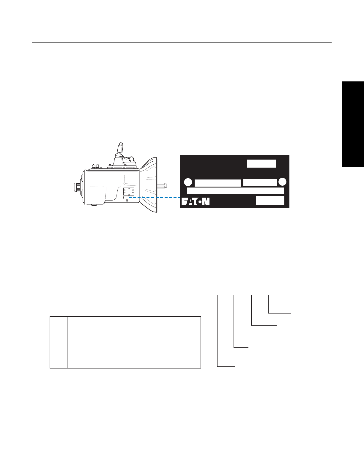
Transmission model designation and other transmission identification information are stamped on the serial tag. To identify the
transmission model and serial number, locate the tag on the transmission and then locate the numbers as shown. Figure 1-1 below
shows the tag which is located on the transmission.
When calling for service assistance or parts, have the model and serial numbers handy
Do not remove or destroy the transmission identification tag!
PTO Code
Eaton Fuller
Transmissions
Model
FRO-14210-C
Eaton Corporation
Transmission Div
Kalamazoo, MI 49003
Fig 1-1
Transmission Tag and Location
Model Number
The model number gives basic information about the transmission and is explained below. Use this number when calling for service assistance or replacement parts.
Made
In
Serial
Model Designations
Serial Number
The serial number is the sequential identification number of the transmission. Before calling for service assistance, write the number down as it may be needed.
Bill of material or Customer number
This number may be located below the model and serial numbers. It is a reference number used by Eaton®.
Eaton
Fuller
Model Designation Prefix
See options below:
Definition
Prefix
FR
Fuller Roadranger Twin Countershaft
FRF
w/ Forward Shift Bar Housing
FRO
w/ Overdrive
FROF
w/ Overdrive and Forward Shift Bar Housing
FR -
14210C
2
= Helical Auxilary Gearing and
"Multi-Mesh" Front Gearing
This (x) 100 = Nominal Torque Capacity
Ratio Set
Forward Speeds
5
Page 10
Model Designations
Model Options
Torque Rating
The torque rating of the transmission specified in the model number is the input torque capacity in lb. ft.. Various torque ratings
are available. For more information, call the Roadranger Help Desk at 1-800-826-HELP (4357).
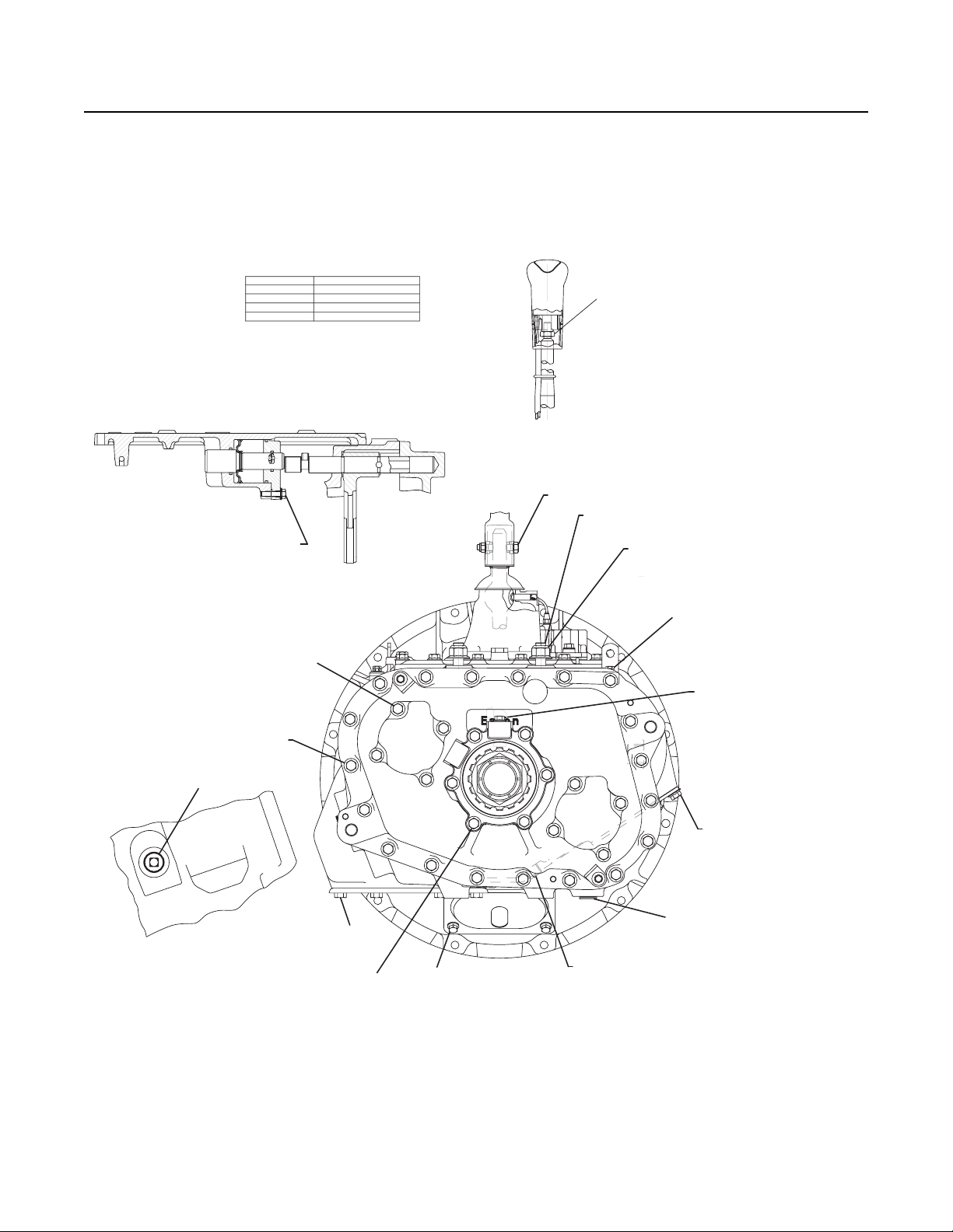
Two types of shift bar housings are available for this transmission. Both are described and shown below.
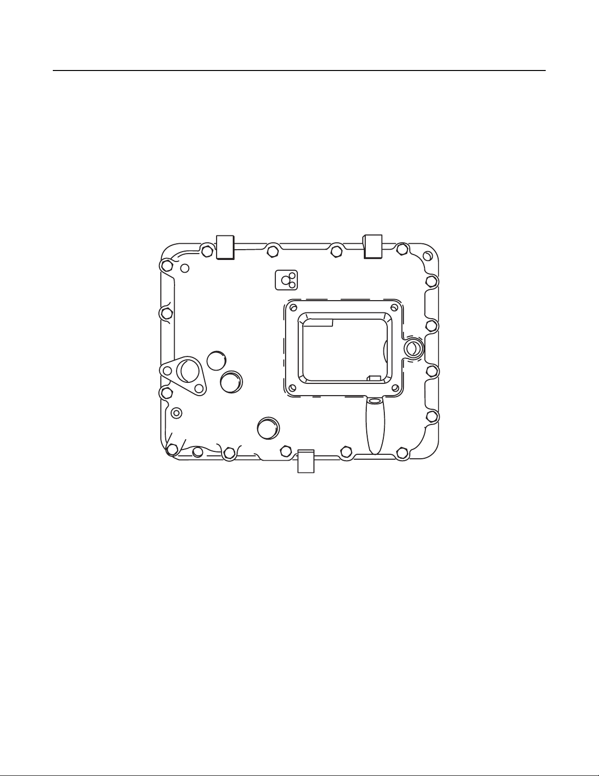
Shift Bar housings
Standard: The standard shift bar housing has a gear shift lever opening that is located toward the rear of the transmission. The
housing is shown in figure 1-2.
Fig 1-2
6
Page 11
Model Designations
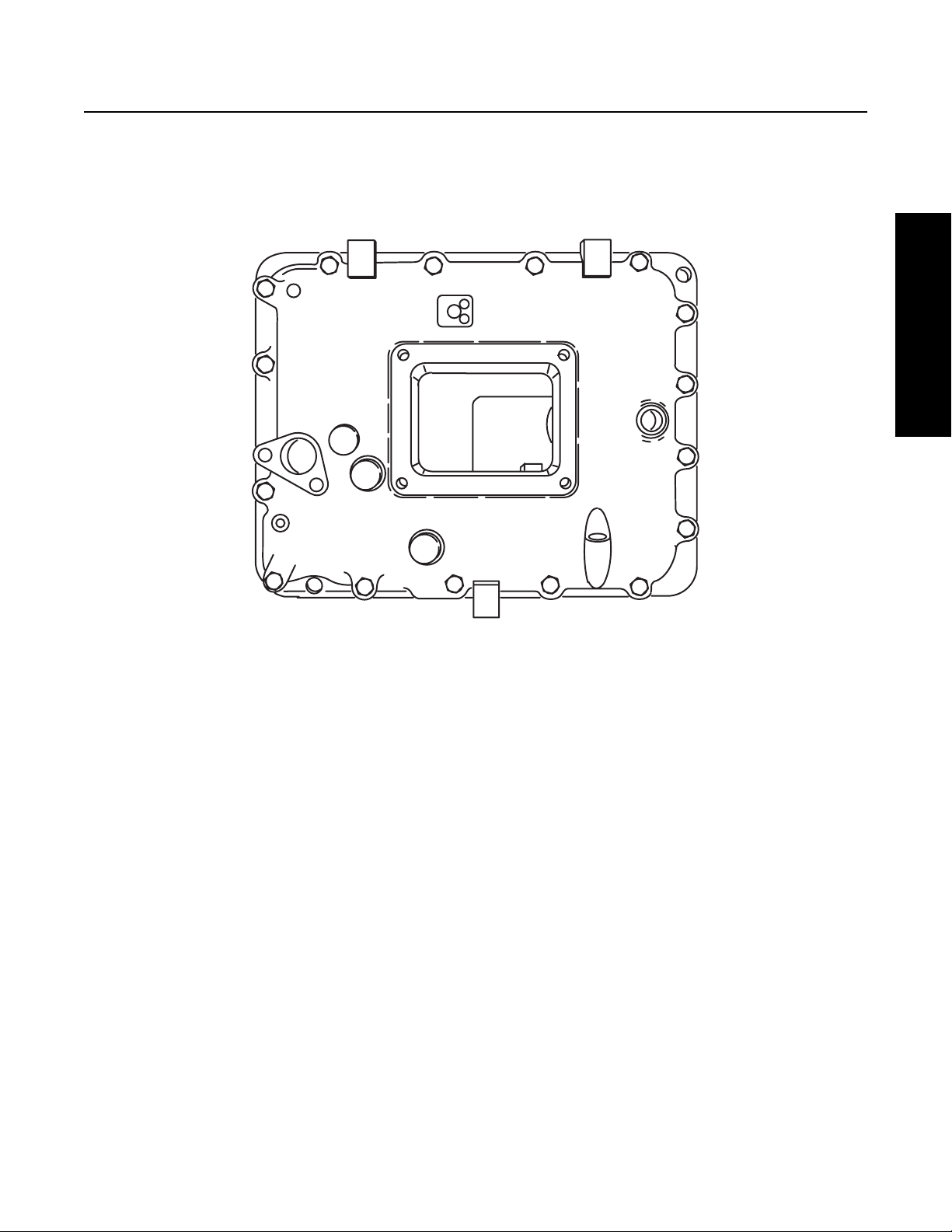
Forward Opening: The forward opening shift bar housing has a gear shift lever opening located three inches closer to the front of
the transmission than the standard opening. This forward design allows greater flexibility in mounting the transmission and in
indicated by an “F” in the model number. The housing is shown in figure1-3.
Model Designations
Fig 1-3
Lubrication Pumps
Two types of lubrication pumps are available for use on this transmission and are described below:
PTO Driven: A PTO driven pump is externally mounted on the 6 or 8 bolt PTO openings and driven off the PTO gear.
Auxiliary Countershaft: An auxiliary countershaft pump is mounted on the rear of the transmission and driven off the auxiliary
countershaft.
Power Take Off (PTO) Usage
PTO’s can be mounted in the following ways:
6 or 8 Bolt: The 6 or 8 bolt openings are standard with the transmission. The PTO is mounted to the opening and driven from the
PTO gear on the front countershaft.
Thru-Shaft: The thru-shaft PTO mounts on the rear of the transmission. It requires a special auxiliary housing and main case countershaft with internal splines.
7
Page 12

Lubrication
Lubrication Specifications
Note: For a list of Eaton Approved Synthetic Lubricants, see TCMT-0021 or call 1-800-826-HELP (4357).
Note: The use of lubricants not meeting these requirements will affect warranty coverage.
Note: Additives and friction modifiers must not be introduced. Never mix engine oils and gear oils in the same transmission.
IMPORTANT
Transmission filters should be changed during regular lube intervals. Inspection of the transmission filter should be conducted during preventive maintenance checks for damage or corrosion. Replace as necessary.
Buy from a reputable dealer
For a complete list of approved and reputable dealers, write to: Eaton Corporation, Worldwide Marketing Services, P.O. Box 4013,
Kalamazoo, MI 49003
Transmission Operating Angles
If the transmission operating angle is more than 12 degrees, improper lubrication will occur. The operating angle is the transmission mounting angle in the chassis plus the percent of upgrade (expressed in degrees). For operating angles over 12 degrees, the
transmission must be equipped with an oil pump or cooler kit to insure proper lubrication.
Operating Temperatures with Oil Coolers
The transmission must not be operated consistently at temperatures above 250° F. Operation at temperatures above 250°F
[121°C] causes loaded gear tooth temperatures to exceed 350°F [177°C] which will ultimately destroy the heat treatment of the
gears. If the elevated temperature is associated with an unusual operating condition that will reoccur, a cooler should be added,
or the capacity of the existing cooling system increased.
The following conditions in any combination can cause operating temperatures of over 250° F [121°C]:
• Operating consistently at slow speed.
• High ambient temperatures.
• Restricted air flow around transmission.
• Use of engine retarder.
• High horsepower operation.
Note: Transmission coolers must be used to reduce the operating temperatures when the above conditions are encountered.
Oil Cooler Chart
Table 4
Transmission Oil Coolers are:
Recommended
• With engines of 350 H.P. and above.
Required
• With engines 399 H.P. and above and GCW’s over 90,000 lbs.
• With engines 399 H.P. and above and 1400 lb. ft. or greater torque.
• With engines 1500 lb. ft. and above
8
Page 13

Table 4
Transmission Oil Coolers are:
18-speed AutoShift transmissions require use of an Eaton supplied oil-to-water cooler or approved equivalent.
• With engines 450 H.P. and above.
Lubrication
Lubrication
9
Page 14
Lubrication
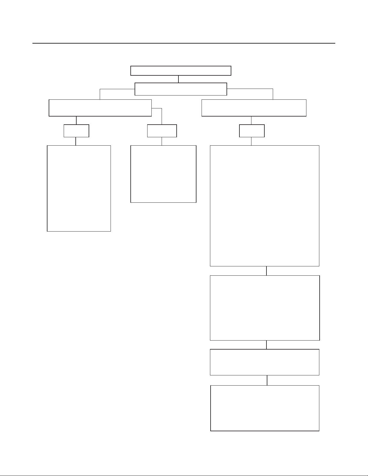
Oil Leak Inspection Process
Inspect for Oil Leak
Determine if it is a Weep or a Leak
Weep: Stained, damp, no drips, light oil film,
dirt adhered to the contaminated area.
Gasket Rear Seal Leak
Leak: Extremely wet or dripping of oil in the
contaminated area.
Step 1
1. Clean suspected oil weep
area with a clean dry cloth
or mild soluble degreaser.
2. Ensure lube is to proper
level.
3. Notify the customer that it
is only a weep and it is not
considered to be detrimental
to the life of the transmission.
4. Repair is complete.
1. Do not repair: Rear seal is
designed to allow min
seepage (refer to Roadranger
TCSM-0912 Seal Maintance
Guide).
2. Ensure lube is to proper
level.
imal
Step 2
1. Determine the origin of the leak path.
2. If origin of leak is obvious skip to Step 3.
3. If the origin of the oil leak is not obvious then
use either of the two following steps to determine
the oil leak:
Note: Do not use a high pressure spray washer to
clean the ar
force contamination into the area of concern and
temporarily disrupt the leak path.
i. Clean area with a clean dry cloth or mild
soluble degreaser and fill the transmission to
the proper lube level.
OR
ii. Clean the area as noted above and insert tracer
dye into the tr
transmission to proper lube level.
ea. Use of a high pressure spray may
ansmission lube and fill
Operate vehicle to normal transmission operating
temperature and inspect the area for oil leak(s)
visually or if tracer dye was introduced use an UVL
(Ultraviolet Light) to detect the tracer dye’s point
of origin.
Note: When i
make sure the assumed leak area is not being
contaminated by a source either forward or above
the identified area such as the engine, shift tower,
shift bar housing, top mounted oil cooler, etc...
nspecting for the origin of the leak(s)
Step 3
Once the origin of the leak is identified, repair the
oil leak using proper repair proced
designated model service manual.
ures from the
Step 4
After the repair is completed, verify the leak is
repaired and operate the vehicle to normal
transmission operating temperature.
Inspect repaired area to ensure oil leak has been
eliminated. If the leak(s) still occurs, repeat steps
or contact the Roadranger Call Cen
1-800-826-4357.
ter at
10
Page 15
Transmission Operation
10
1-2-3-4-5
RAISE RANGE SELECTOR
10-9-8-7-6 MOVE RANGE SELECTOR DOWN
5-4-3-2-1
6
1
3
2
4
8
9
7
10
5
6-7-8-9-10
Transmission Operation and Theory
Transmission Operation and
Transmission Operation
This Eaton® Fuller® Roadranger® transmission model contains ten forward speeds and two and reverse speeds. The gear shift
lever mechanically engages and disengages five forward gears and one reverse gear in the transmission front section. The range
lever on the shift knob allows the operator to control an air shifted auxiliary section to provide a low and high “range”. The five
forward gears selected in low range are used again in high range to provide the remaining 5 progressive forward gear ratios.
Once the highest shift lever position (5th gear) is obtained in low range, the operator preselects the range shift lever for high range.
The range shift occurs in neutral as the shift lever is moved from 5th gear position to 6th gear position.
When downshifting, the operator preselects the range lever for low range and the range shift occurs automatically as the shift lever
is moved to the next gear position. Refer to the illustrations in the “Power Flow” portion of this section.
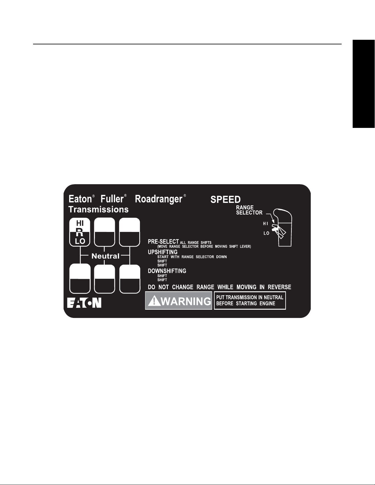
Shift Patterns
A Shift pattern decal that explains how to properly shift the transmission should be in your vehicle. The decal is shown in Figure
2-1. If it has been lost, a replacement may be obtained from any Eaton® parts distributor.
10
Theory
Figure 2-1 Shift Pattern Decal
10
RAISE RANGE SELECTOR
1-2-3-4-5
6-7-8-9-10
10-9-8-7-6 MOVE RANGE SELECTOR DOWN
5-4-3-2-1
11
Page 16
Transmission Operation and Theory
Operating Instructions
Initial Start - Up
WARNING
Before starting a vehicle always be seated in the driver’s seat, move the shift lever to neutral, and set the parking brakes.
CAUTION
Before moving a vehicle, make sure you understand the shift pattern configuration.
1. Make sure the shift lever is in neutral and the parking brakes are set.
2. Turn on the key switch, and start the engine.
3. Allow the vehicle air pressure to build to the correct level. Refer to your “Operator and Service Manual” supplied with the
truck.
4. Apply the service brakes.
5. Release the parking brakes on the vehicle.
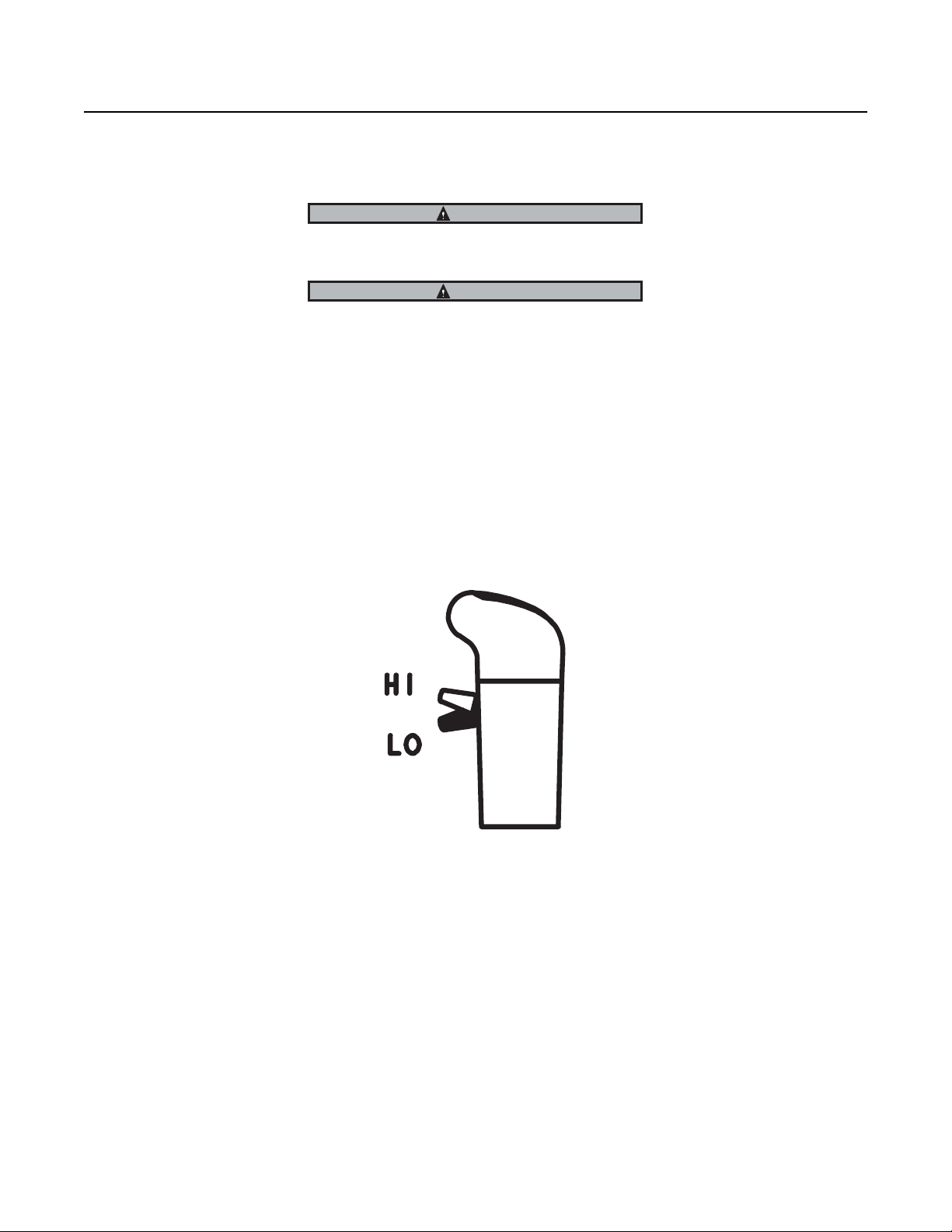
6. Make sure the Range Selector is down in the low range position as shown below in Figure 2-2.
Figure 2-2
7. Depress the clutch pedal to the floor.
8. Move the shift lever to the desired initial gear.
9. Slowly release the clutch pedal and apply the accelerator.
12
Page 17

Upshifting
Transmission Operation and Theory
Transmission Operation and
CAUTION: Never move the Range Selector with the shift lever in neutral while the vehicle is moving.
1. Move the shift lever, double-clutching, to the next desired gear position in low range.
Range shift - low to high Range (5th to 6th)
2. When in last gear position for low range and ready for the next upshift, pull up the Range Selector and move the shift
lever, double-clutching, to the next higher speed position according to your shift pattern. As the shift lever passes
through neutral, the transmission will automatically shift from low to high range.
Note: If after attempting a range shift to high, the transmission remains in neutral with the shift lever in gear, the range synchro-
nizer protection device may deactivated. Move the shift lever into neutral to allow the range shift to complete, and then move
the shift lever back into gear.
3. Continue upshifting, double-clutching, to the next desired gear position in high range
Downshifting
1. Move the shift lever, double-clutching, to the next desired gear position in high range
Range shift from High Range to Low Range (6th to 5th)
2. While in 6th and ready for the next downshift, preselect low range, and push the Range Selector down.
3. Move the shift lever, double-clutching, to the next desired gear position in low range. As the shift lever passes through
neutral, the transmission automatically shifts from high range to low range.
4. Continue downshifting, double-clutching, to the next desired gear position in low range
Theory
Double - Clutching Procedure
1. Depress the pedal to disengage the clutch.
2. Move the shift lever to neutral.
3. Release the pedal to engage the clutch.*
a. Upshifts-decelerate engine until engine RPM and road speed match.
b. Downshifts-accelerate engine until engine RPM and road speed match.
4. Quickly depress the pedal to disengage the clutch and move the shift lever to the next gear speed position.
5. Release the pedal to engage the clutch.
Note: * By engaging the clutch with the shift lever in the neutral position, the operator is able to control the mainshaft gear RPM
since it is regulated by engine RPM. This procedure allows the operator to speed up or slow down the mainshaft gearing to
properly match the desired gear speed and output shaft speed.
13
Page 18

Transmission Operation and Theory
Additional Operating Information
Preselect
IMPORTANT: Always preselect all range shifts when upshifting or downshifting. Preselection requires that the Range Selector is
moved to the needed position before starting the lever shift.
Preselected range shifts are completed automatically as the lever is moved through neutral and into the next gear. Preselecting all
range shifts prevents damage to the transmission and provides for smoother shifts.
SynchroSaver™
The transmission contains a range synchronizer protection device to prevent damage to the high range synchronizer. If the shift
lever engages a front section gear prior to completion of the air shift into high range, the range synchronizer remains in neutral,
preventing damage to the range synchronizer. If this neutral condition occurs, the operator must shift the lever to neutral and then
back into gear to complete the range shift.
Clutch Brake (Used with pull-type clutches)
The Clutch Brake is applied by fully depressing the clutch pedal to the floor board. When applied, the brake slows down and can
stop the transmission front box gearing. It is a disc-type brake incorporated into the clutch and transmission drive gear assemblies. Never use the Clutch Brake when upshifting or downshifting. Use only for initial gear engagement when the vehicle is standing still.
Countershaft Brake (Used with push-type clutches)
The control button is mounted on the shift lever just below the shift knob. To operate the brake, disengage the clutch, press down
the control button, and shift into 1st or reverse. This is an air operated mechanical brake which slows down the transmission gearing by forcing a piston against the countershaft PTO gear.
Note: Never use the Countershaft Brake when upshifting or downshifting. Use only for initial gear engagement when the vehicle
is standing still.
Driver Instruction Booklet
Complete operation instruction can be found in the Drive Instruction Booklet TRDR-0515.
14
Page 19

Tools
Tool Specifications
Some repair procedures pictured in this manual show the use of specialized tools. Their actual use is recommended as they make
transmission repair easier, faster, and prevent costly damage to critical parts.
For the most part, ordinary mechanic's tools such as socket wrenches, screwdrivers, etc., and other standard shop items such as
a press, mauls and soft bars are the only tools needed to successfully disassemble and reassemble any Eaton®Fuller® transmission.
The following tables list and describe the typical tools required to properly service this model transmission above and beyond the
necessary basic wrenches, sockets, screwdrivers, and prybars.
General Tools
The following tools are available from several tool manufacturers such as Snap-On, Mac, Craftsman, OTC, and many others.
Table 5 General Tools
TOOL PURPOSE
0 - 100 lb. ft. 1/2" drive Torque Wrench General torquing of fasteners (Typically 15-80 lb. ft.)
0 - 600 lb. ft. 3/4" or 1" drive Torque Wrench Torquing of output nut to 500 lb. ft.
0 - 50lb. in. 3/8" drive Torque Wrench General torquing of fasteners
0 - 30lb. in. 1/4" drive Torque Wrench Torquing of capscrews to 7 lb. in. during auxiliary countershaft
bearing endplay setting procedure
70 MM or 2 2/4" Socket - Standard Depth To remove the output yoke nut
Large Brass Drift Used to protect shafts and bearings during removal
Large Dead Blow Hammer or Maul To provide force for shaft and bearing removal
Snap Ring Pliers - Large Standard External To remove the snap rings at the auxiliary drive gear, input shaft
bearing, and countershaft bearings
Tool s
Feeler Gauges To set mainshaft washer endplay and auxiliary tapered bearing
endplay
Rolling Head (Crow's Foot) Prybar To remove the auxiliary drive gear bearing
(2) Air Pressure Gauges 0-100 PSI (0-1034 kPa) To troubleshoot and verify correct operation of air system
Universal Bushing Driver To remove and install clutch housing bushings. Bushing OD =
1.125", ID = 1.000"
15
Page 20

Tools
The following special tools are designed for this Eaton®Fuller® transmission. The addresses and phone numbers of the tool suppliers are listed after the table. This list is provided as a convenience to our customers. These tools are manufactured by independent companies with no relationship to Eaton®Fuller®. Eaton®Fuller® does not warrant the fit or function of the listed tools. To
obtain the tools, contact the tool supplier directly.
REF.
NO.
T1 Output Yoke Puller May be required to remove a rusted
T2 Auxiliary Section Hanger To support, or hang, the auxiliary sec-
T3 Auxiliary
Countershaft
Support and Shim Tool
T4 Shift Lever Spring
Installation Tool
(Tension Spring Driver)
T5 Slide Hammer To remove the output seal and reverse
T6 Bearing Puller To remove front section countershaft
TOOL PURPOSE G & W TOOL
output yoke.
tion in the horizontal position.
To hold the auxiliary countershafts in
position while installing the auxiliary
section in the horizontal position. Also
to simplify the
checking and setting of the auxiliary
countershaft bearing endplay.
To install the shift tower tension
spring.
idler shafts. Requires 1/2"-13 threads.
(Optional, idler shaft can be driven out
from front.)
bearings.
GREAT LAKES
NO.
SP-450 7075
G-40 T-125 5061
G-250
(can also use
G-251)
G-116 T-170
G-70 (with g247D for Rev.
Idler removal)
G-246 T-2 7070A Kit
TOOL NO.
T-311 5062
T-150 (with T151 metric
adapter)
OTC TOOL
NO.
1155 Slide
Hammer /
8007 1/2" -13
Adapter
T7 Bearing Driver To install front section countershaft
bearings
T8 Bearing Driver To install the front countershaft rear
bearings
T9 Countershaft
Support Tools (2)
T10 Input Bearing Driver To install input bearing on input shaft. G-35 T-120 5066 (2" shaft)
T11 Bearing Puller To remove the auxiliary countershaft
T12 Bearing Driver To install the auxiliary countershaft ta-
T13 Output Seal Removal Tool To remove the output seal in
* Tool numbers are referenced in the service procedures.
16
To support and locate the front
section countershafts during
bearing removal and installation.
tapered bearings.
pered bearings.
chassis. Can use slide hammer.
G-230 T-101 Kit or
T-120 with T120A adapter
G-230 T-101 Kit
G-54 T-132 7109
G-247 or
G-247A
G-230 T-101 Kit
1123 / 927
Use 27315
hook with 1155
slide hammer
Page 21

Tools
REF.
NO.
T14 Auxiliary Section Removal
Adapter Plate
T15 Mainshaft Hook To assist in lifting of mainshaft from
T16 Input Bearing Puller To remove input bearing. G-38 T-3 7070A Kit
T17 Bearing Race Puller To remove the auxiliary countershaft
T18 Bearing Race Installer To install the auxiliary countershaft ta-
* Tool numbers are referenced in the service procedures.
TOOL PURPOSE G & W TOOL
NO.
To attach transmission jack to
auxiliary section for auxiliary
section removal in chassis.
front section.
tapered bearing outer races.
pered bearing outer races.
G-115 49611
G-225 T-165
G-247B (used
with G-70
slide hammer)
G-247C (used
with G-230)
GREAT LAKES
TOOL NO.
T-157 with
T-150
T-101 Kit 27524/27530
OTC TOOL
(Used with OTC
transmission
jack P/N 5019.)
7136 puller attached to 1155
slide hammer
discs used with
27488 handle
and 10020
screw.
Table 7 Shop Equipment
20 Ton capacity press To press countershaft gears from countershaft.
NO.
Tool s
Special Tools Manufacturers
Below are the addresses and phone numbers of the companies that make tools specifically for Eaton® Fuller® transmissions.
G & W Tool Company Great Lakes Tool O.T.C.
907 S. Dewey Ave 8530 M-89 655 Eisenhower Dr.
Wagoner, OK 74467 Richland, MI 49083 Owatonna, MN 55060-1171
800-247-5882 800-877-9618 800-533-6127
www.gwtoolco.com 269-629-9628
www.greatlakestools.com
17
Page 22

Tools
Eaton Aftermarket Parts
The following tools are available through Eaton Aftermarket Parts. To obtain any of the tools listed, contact your local Eaton parts
distributor.
TOOL PURPOSE EATON PART NUMBER
5/32" Air Line Release Tool To remove 5/32" air lines from
push-to-connect fittings.
Air Line Cutting Tool To cut plastic air lines smoothly
and squarely.
Output Seal Driver To install output seal. For 7 series: Eaton P/N 5564501 driver.
Output Seal Slinger Driver To install output seal slinger. For 7 series: Eaton P/N 71223.
P/N 4301157 included in kit K-2394.
P/N 4301158 included in kit K-2394.
For 9 series: Use Eaton P/N 5564509 adapter with 5564501 driver. Both parts included in Complete Eaton Seal Kit P/N K-3651.
For 9 series: Eaton P/N 4303829.
18
Page 23
Torque Specifications
Transmission Overhaul Procedures-Bench Service
FRONT BEARING COVER CAPSCREWS
54-61 N.m [40-45 lb
M10x1.5 THREAD
CLUTCH HOUSING STUDS
81 N.m [60 lb.ft.] MIN
M16x2 THREAD
DRIVEN UNTIL BOTTOMED
.ft.]
CLUTCH HOUSING NUTS
ALUMINUM HOUSING
CAST IRON HOUSING
244-271 N.m [180-200 lb
M16x1.5 THREAD
SHIFT BLOCK TO SHIFT ROD CAPSCREW
54-61 N.m [40-45 lb
M10x1.5 THREAD
.ft.]
.ft.]
SHIFT LEVER HOUSING CAPSCREWS
54-61 N.m [40-45 lb
M10x1.5 THREAD
AUX DRIVE GEAR
BEARING RETAINER CAPSCREWS
54-61 N.m [40-45 lb
M10x1.5 THREAD
.ft.]
.ft.]
Procedures-Bench Service
Transmission Overhaul
CLUTCH HOUSING CAPSCREWS
ALUMINUM HOUSING
CAST IRON HOUSING
97-108 N.m [72-80 lb
M12x1.75 THREAD
.ft.]
COUNTERSHAFT FRONT BEARING
RETAINER CAPSCREWS
122-162 N.m [90-120 lb
.625-18-THREAD
.ft.]
OUTPUT SHAFT NUT
610-677 N.m [450-500 lb
M48x2 THREAD
USE NYLON LOCKING INSERT
(OILED AT YOKE INSTALLATION)
.ft.]
19
Page 24
Transmission Overhaul Procedures-Bench Service
PIPE THREAD TORQUE SPECIFICATIONS. UNLESS OTHERWISE SPECIFIED:
PIPE THREAD SIZE
.0625 - 27 6.8-9.5 N.m [60-84 lb.in]
.125 - 27 9.5-13.6 N.m [84-120 lb.in]
.250 - 18
.375 - 18
RANGE COVER TO SBH
RANGE CYL CAPSCREWS
27-31 N.m [20-23 lb
.ft.]
M8x1.25 THREAD
AUX C'SHAFT REAR BEARING COVER CAPSCREWS
54-61 N.m [40-45 lb.ft.]
M10x1.5
AUX HOUSING CAPSCREWS
54-61 N.m [40-45 lb
M10x1.5 THREAD
.ft.]
OIL FILL PLUG
47-67 N.m [35-50 lb
1.0625-12 THREAD
.ft.]
HYDRAULIC LINE SEALANT
20.3-27.1 N.m [180-240 lb.in]
33.9-47.5 N.m [300-420 lb.in]
MASTER VALVE JAM NUT
48-61 N.m [35-45 lb
.500-13 THREAD
SHIFT LEVER SHOULDER BOLT AND NUT
14-16 N.m [10-12 lb.ft.]
.3125-18 THREAD
SUPPORT STUDS
81 N.m [60 lb.
M16x2 THREAD
DRIVE UNTIL BOTTOMED
SUPPORT STUD NUTS
230-257 N.m [170-190 lb
M16x1.5 THREAD
.ft.]
ft.]
.ft.]
CAPTIVATED LIFTING EYE CAPSCREWS
54-61 N.m [40-45 lb
M10x1.5 THREAD
SPEEDO SENSOR CAPSCREW
27-31 N.m [20-23 lb
M8x1.25 THREAD
.ft.]
.ft]
20
LARGE PTO COVER CAPSCREWS
77-88 N.m [57-65 lb
M12x1.75 THREAD
REAR BEARING COVER CAPSCREWS
54-61 N.m [40-45 lb
M10x1.5 THREAD
.ft.]
.ft.]
HAND HOLE COVER CAPSCREWS
19-24 N.m [14-18 lb
.3125-18 THREAD
.ft.]
OIL DRAIN PLUG
61-74 N.m [45-55 lb
.750 PIPE THREAD
THERMOCOUPLE PLUG
54-67 N.m [40-50 lb
.500 PIPE THREAD
SMALL PTO COVER CAPSCREWS
54-61 N.m [40-45 lb.ft.]
M10x1.5 THREAD
.ft.]
.ft.]
Page 25
Power Flow
Power Flow Diagrams
An understanding of the engine’s power flow through a transmission in each particular gear will assist the technician in troubleshooting and servicing a transmission.
The Eaton Fuller Roadranger transmission can be thought of as two separate “transmissions” combined into one unit. The first
“transmission” or front section contains six gear sets which are shifted with the gear shift lever. The second “transmission” called
the auxiliary section, contains two gear sets and is shifted with air pressure.
Note: This transmission is referred to as a constant mesh type transmission. When in operation, all gears are turning even though
only some of them are transferring power.
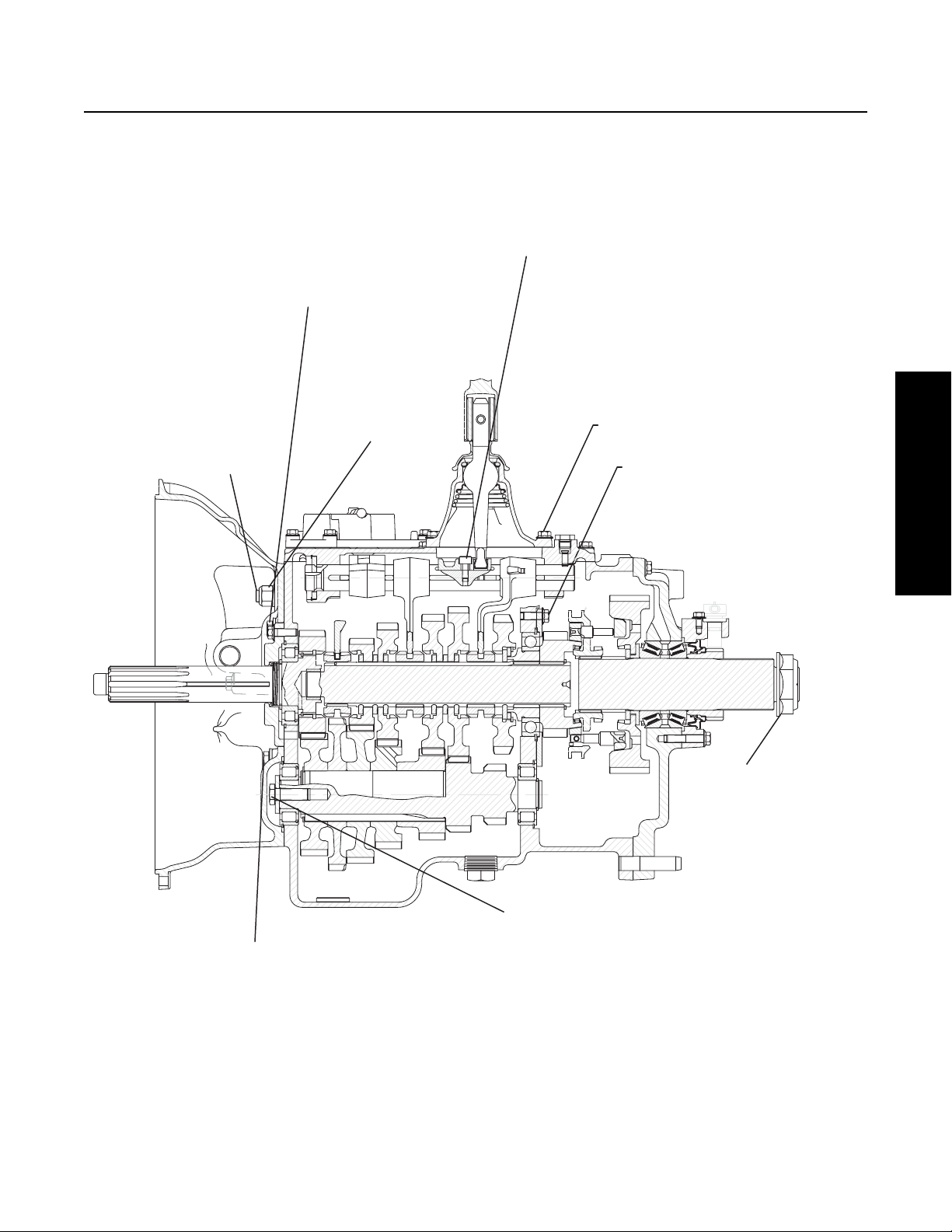
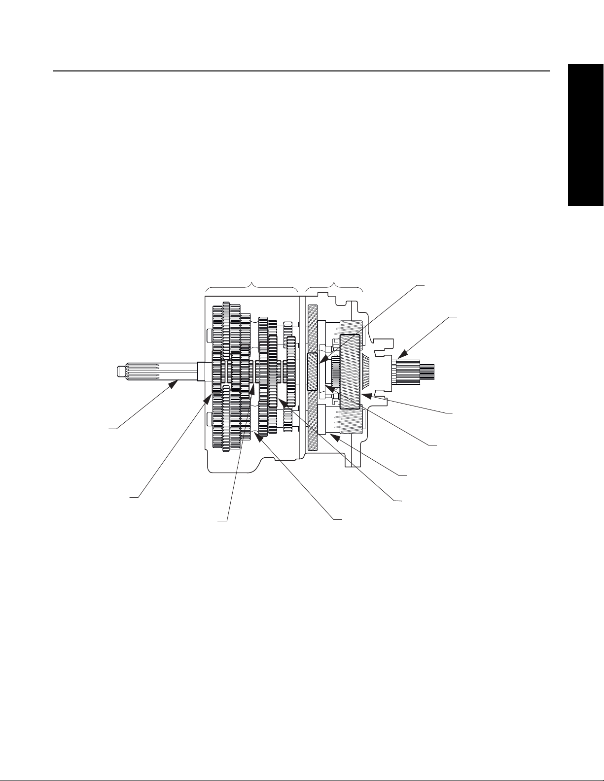
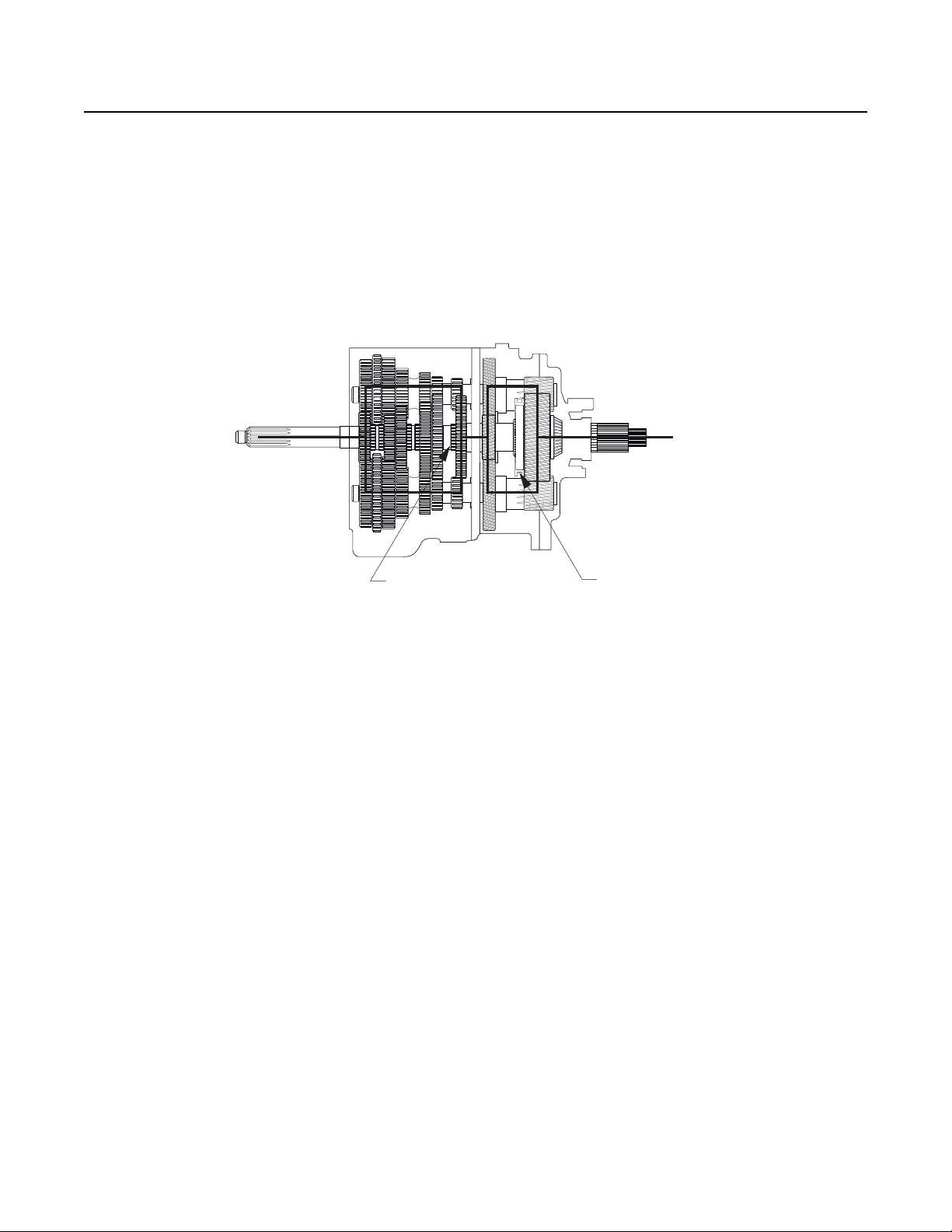
Figure 2-3 below shows the transmission with the main components called out. Note that the transmission is in the neutral position because the sliding clutches are all in their center positions and not engaged is any gears.
Front Section
Auxiliary Section
Auxiliary Drive Gear
Output Shaft
(Auxiliary Mainshaft)
General Information
Input Shaft
Main Drive Gear
Sliding Clutch
Figure 2-3. Transmission Components Important for Understanding Power Flow
Countershaft
Auxiliary Mainshaft
Reduction Gear
Range Sliding Clutch
Auxiliary Countershaft
Mainshaft Gear
21
Page 26
Power Flow
k
Front Section Power Flow
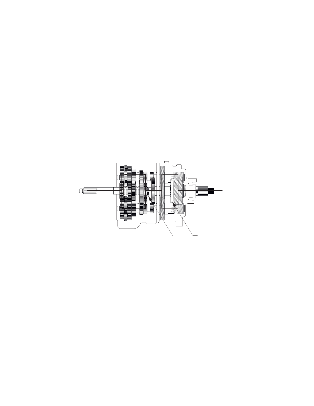
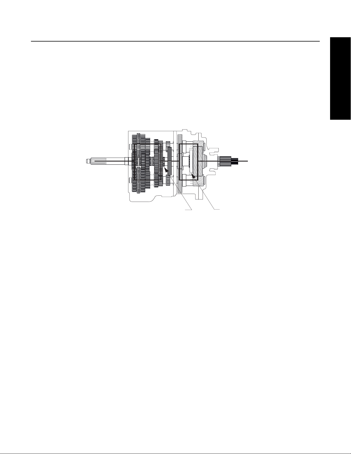
Note: The heavy lines in Figure 2-4 outline the power flow description below. For help in understanding the transmission compo-
nents, refer to Figure 2-3.
1. Power (torque) from the vehicle’s engine is transferred to the transmission’s input shaft.
2. The input shaft rotates the main drive gear through internal splines in the hub of the gear.
3. The main drive gear meshes with both countershaft driven gears and the torque is split between both countershafts.
4. Because the countershaft gears are in constant mesh with the mainshaft gears, all the front section gearing rotates. However, only the engaged mainshaft gear will have torque. External clutching teeth on the sliding clutch will engage internal
clutching teeth on the selected mainshaft gear. Torque will now be provided from both opposing countershaft gears, into
the engaged mainshaft gear, and through the sliding clutch to the front section mainshaft.
5. The rear of the front section mainshaft is spined into the auxiliary drive gear and torque is now delivered to the auxiliary
section.
Figure 2-4 Front Section Torque (1st Gear)
Sliding Clutch Forward
Sliding Clutch Bac
22
Page 27
Power Flow
k
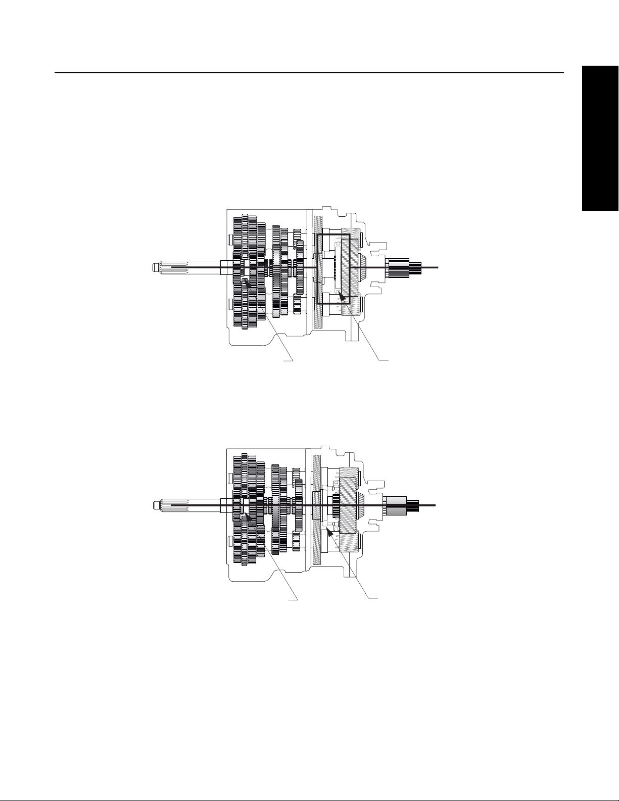
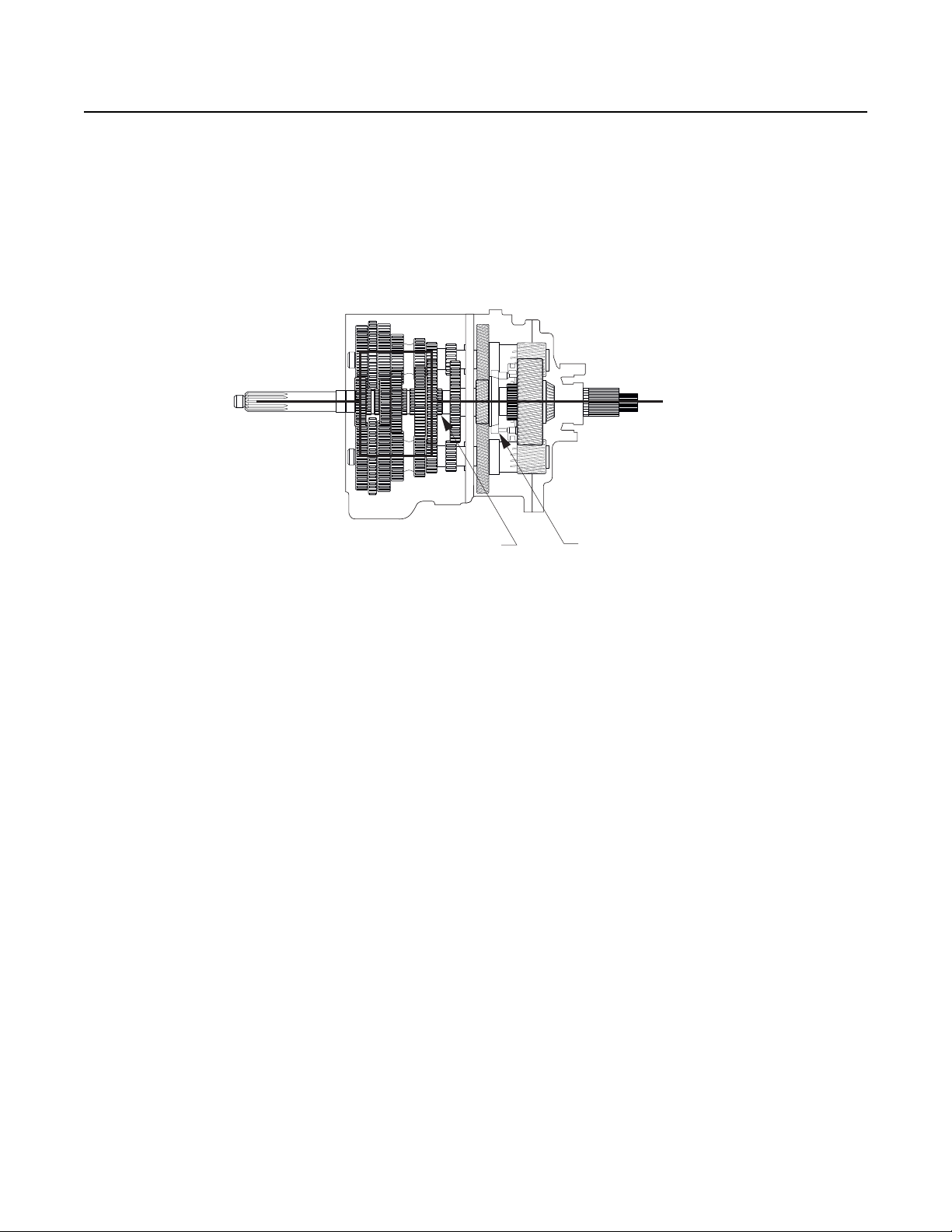
Front Section Power Flow - Direct gear
In direct gear (5th/10th for FR model, 4th/9th for FRO model), the front sliding clutch is moved forward and engages into the back
of the main drive gear. Torque will flow from the input shaft to the main drive gear, main drive gear to sliding clutch, sliding clutch
straight into the front section mainshaft which delivers the torque to the auxiliary drive gear.
Note: All countershaft and mainshaft gears will rotate, but the gears will not be loaded.
Sliding Clutch Forward
Sliding Clutch Bac
General Information
Figure 2-5 5th Gear FR, 4th Gear FRO
Sliding Clutch Forward
Figure 2-6 10th Gear FR, 9th Gear FRO
Sliding Clutch Forward
23
Page 28
Power Flow
Front Section Power Flow - Reverse Gear
Torque will flow from the countershafts to the reverse idler gears. Torque will then flow from the reverse idler gears to the mainshaft reverse gear. Torque will now travel through the mainshaft reverse gear, the sliding clutch in the reverse position and then
to the mainshaft and auxiliary drive gear.
Note: The idler gears cause the reversal of rotation.
Figure 2-7 Reverse Gear - Low Range
Sliding Clutch Back Sliding Clutch Back
24
Page 29
Power Flow
Auxiliary Section Power Flow - Low Range
The auxiliary drive gear transfers torque to both auxiliary countershafts.
If the auxiliary section is in low range, the range sliding clutch is rearward and engaged into the auxiliary mainshaft reduction gear.
Torque will flow from the auxiliary countershafts, into the auxiliary mainshaft reduction gear, through the range sliding clutch and
then into the output shaft (auxiliary mainshaft).
Sliding Clutch Forward
Sliding Clutch Back
General Information
Figure 2-8 Low Range (Sliding Clutch Back)
25
Page 30
Power Flow
Auxiliary Section Power Flow - High Range
If the auxillairy section is in high range, the range sliding clutch is forward and engaged into the back of the auxiliary drive gear.
Torque will flow from the auxillairy drive gear to the range sliding clutch. Because the range sliding clutch has internal splines
which connect to the output shaft, torque will flow straight through the auxiliary section.
Note: The auxiliary gearing will still turn, but the gears will not be loaded.
Sliding Clutch Forward
Figure 2-9 High Range Selected (Sliding Clutch Forward)
Sliding Clutch Forward
26
Page 31

Power Flow
k
k
FR/FRO-1X210
1st Gear
2nd Gear
Sliding Clutch Forward
General Information
Sliding Clutch Bac
3rd Gear
Sliding Clutch Back
Sliding Clutch Forward
Sliding Clutch Bac
Sliding Clutch Back
27
Page 32

Power Flow
k
4th Gear-FR/Direct Drive Transmission
5th Gear- FRO/Overdrive Transmission
5th Gear- FR/Direct Drive Transmission
4th Gear FRO/Overdrive Transmission
Sliding Clutch Forward
6th Gear
Sliding Clutch Back
Sliding Clutch Back
Sliding Clutch Bac
28
Sliding Clutch Forward
Sliding Clutch Forward
Page 33

Power Flow
7th Gear
8th Gear
Sliding Clutch Back
General Information
Sliding Clutch Forward
9th Gear-FR/Direct Drive Transmission
10th Gear-FRO/Overdrive Transmission
Sliding Clutch Back
Sliding Clutch Forward
Sliding Clutch Forward
Sliding Clutch Forward
29
Page 34

Power Flow
10thGear-FR/Direct Drive Transmission
9th Gear-FRO/Overdrive Transmission
Sliding Clutch Forward
Sliding Clutch Forward
30
Page 35

Air System Troubleshooting
Air System Troubleshooting
The symptoms listed below are covered on the following pages. Before beginning any of those troubleshooting procedures, place
the transmission in neutral and move the range selection lever from low to high. Listen for any constant air leak from the shift
knob, air module base (exhaust), or transmission breather. If a constant leak is heard, go to that particular leak troubleshooting
procedure first.
If you do not see the symptom you need to correct, refer to the General Troubleshooting chart.
Symptom
• Air Leak from Air Module Base (Exhaust Leak)
• No or Slow Range Shift into High (Shift into low range is good)
• No or Slow Range Shift into Low (Shift into high range is good)
• Constant Air Leak from Shift Knob
• Range Shifts in Gear
• Air Leak from Transmission Breather or Transmission Case is Pressurized
Note: Use the air system troubleshooting procedures for part replacement only if the symptom can be duplicated. If the problem
is intermittent, parts that are not defective could be replaced.
Note: During all testing, the vehicle air pressure must be greater than 90 PSI (620 kPa). If during testing the pressure falls below
90 PSI (620 kPa), make sure the transmission is in neutral, start the engine and let the pressure build to governor cutoff.
After the pressure reaches the governor cutoff, continue testing. The pressure is critical if the vehicle is equipped with a vehicle air system Pressure Protection Valve that would shut off the air supply to certain air circuits if the system pressure
dropped below a preset level.
General Information
Note: A 0-150 PSI (0-1034 kPa) air gauge with a 1/16" male pipe thread fitting attachment is required for some of the test proce-
dures.
Note: Regulated air pressure is 75 to 85 PSI (517 - 586 kPa).
WARNING
Prior to removing the air module, exhaust the air from it. Failure to exhaust the air module may result in personal injury or
damage to parts from the sudden release of air.
Use care when removing the test port pipe plugs. If air pressure is present on the plug, it can become a projectile during
removal. When removing the “L” plug or “H” plug, pressure can be shut off by selecting the opposite range mode. If removing the “F” plug, exhaust the air to the module inlet.
31
Page 36

Air System Troubleshooting
Air System Symptom - Air leak from Module Base (Exhaust)
Short bursts of air leakage from the module base (exhaust) are normal as the range system is shifted. The module base is defined
as both the interface of the module cover and module base and the extreme underside of the module. Leakage is a problem when
it is audible and constant. Air leakage from the module base may result from either a defective air module or a defective range
piston. The following procedure will identify the defective component.
Test Procedure:
1. Check for air leakage from the module base (exhaust) in each of the four following conditions. (Make sure the range is shifted
when the shift lever is shifted into neutral.)
a. Range selection lever in Low and shift lever in neutral.
b. Range selection lever in Low and shift lever in gear.
c. Range selection lever in High and shift lever in neutral.
d. Range selection lever in High and shift lever in gear.
Record the findings (constant leak or no leak) in the following table.
Range Selector in LOW Range Selector in HIGH
Lever in Neutral
Lever in Gear
2. If the information you recorded at step 1 matches one of the following tables, replace the air module. If your table does not
match either of the tables, it will be necessary to isolate and test the air module separately, continue to step 3.
Range Selector in LOW Range Selector in HIGH
Lever in Neutral No Leak Constant Leak
Lever in Gear No Leak Constant Leak
Range Selector in LOW Range Selector in HIGH
Lever in Neutral Constant Leak Constant Leak
Lever in Gear Constant Leak Constant Leak
WARNING
Failure to exhaust the air pressure may cause personal injury or damage to parts.
3. Exhaust the air pressure from the air module. To do so, the vehicle’s air tanks may need to be exhausted.
4. Leaving all air lines connected to the module, remove the four capscrews attaching the air module to the shift bar housing. Lift
the air module and tilt it to gain access to the two air holes at the underside on the rear capscrew location. Do not damage or lose
the two o-rings used to seal the holes.
5. Block off the air ports on the underside of the module. Use a piece of gasket material or rubber material to seal the bottom of
the module as shown in Figure 4-4 “Air System Nomenclature”.
6. Repressurize the air module with an inlet supply pressure of over 90 PSI (620 kPa). To repressurize the air module, the vehicle
may need to be started and air pressure allowed to build up.
32
Page 37

Air System Troubleshooting
7. Check for air leakage in both high and low range. If air continues to leak constantly from the exhaust, the air module is defective.
If air does not leak, a range cylinder piston or piston seal failure has occurred. Remove the shift bar housing to gain access to the
range shift cylinder.
Air System Symptom - No or Slow Range Shift into High (Shift into Low Range is Good)
This transmission contains a SynchroSaver feature to protect the high range synchronizer. When high range is selected and a front
section gear is engaged, air pressure is supplied to both sides of the range piston, which reduces synchronizer force. Therefore,
if the driver engages a front section gear before the high range synchronizer engages, the high range synchronizer will remain in
neutral. When a front section gear engages before the synchronizer shift completes, the driver must shift the lever back to neutral
to allow the high range synchronizer to complete its shift. Once the range shift is complete, the driver can complete the front section shift.
If the high range synchronizer hangs up or is slow to synchronize, the front section may engage first. The driver complaint will be
that the transmission “neutralizes” on a shift to high range. If this condition occurs, perform the following test of the air system
to eliminate the air system as the source of the problem. If the air system performs properly, then the problem is internal to the
transmission range synchronizer system.
Note: The driver must preselect all range shifts.
Note: If a capscrew or stud is installed too far into the right side (air module side) rear support hole, the fastener can extend too
far into the transmission. The fastener may contact the range yoke and bind the range synchronizer assembly during the
range shift.
Test Procedure
1. Check the shift knob operation.
General Information
On the shift knob, remove the screws holding the plastic skirt. Slide the skirt down and out of the way. Move the range selection
lever up into high range. Disconnect the black line connected to the “P” port on the knob.
Question Result What to do next
Does air come out of the “P” port on the
knob
2. Test the regulator pressure. (Regulator pressure should be between 75 and 85 PSI (517-586 kPa))
Reconnect the “P” line at the shift knob. Locate the two small pipe plugs on the rear of the air module. One is labeled “H” the other
“L”. (See figure 4-1 “Air System Nomenclature”). Install a 0-150 PSI (0-1034 kPa) air gauge in the port marked “H.”
Note: Prior to removing the pipe plug, turn off the air flow by flipping the range selector down into the low range position. The
transmission must be in neutral.
Move the range selector up to the high range position and record the pressure on the gauge. Match the pressure to one of those
on the chart on the next page, and follow the corresponding instructions.
Question Result What to do Next
What is the air pressure at
the “H” port?
75-85 PSI (517-586 kPa)
(to specification)
Yes Repair or replace the knob
No Reconnect the air line to the knob, and con-
tinue to the next step.
Continue to the next step
33
Page 38

Air System Troubleshooting
Question Result What to do Next
Less than 75 PSI
(517 kPa)
Greater than 85 PSI
(586 kPA)
3. Check the spool valve function.
With the shift lever in neutral, move the range selector from low to high several times. Answer the question on the chart below,
and follow the instructions corresponding to the result.
Question Result What to do Next
Does the gauge rapidly go from 7585 PSI (517-586 kPa) in High to 0
PSI in Low?
Yes Air system performs properly. Go to
Warning: The pipe plug to be removed in this procedure is pressurized and could be expelled with great force. To prevent personal injury or damage to parts, exhaust the air module before removing the
plug, and repressurize the air module after installing the gauge.
On the top of the air module, remove the test port pipe plug for filtered vehicle air. (Marked “F” as shown in figure 4-1.)
Install the test gauge in the “F” port, and check the pressure. If the
pressure is less than 90 PSI (620 kPa), repair the vehicle air system
to achieve full vehicle air pressure at the air module inlet, and repeat
the test. If the pressures greater than 90 PSI (620 kPa) and no external air leaks were detected from the air module, shift knob, or
transmission, replace the air module.
Replace the air module
step 5.
No Continue to the next step
4. Isolate and test the air module. Refer to Figure 4-4 “Air System Nomenclature” to see an example of an isolated air module.
WARNING
Failure to exhaust the air module may cause personal injury or damage to parts due to the rapid release of air.
Exhaust the air pressure from the air module. To do so, the vehicle air tanks may need to be exhausted. Remove the four capscrews
attaching the air module to the shift bar housing. Lift the air module and tilt it to gain access to the two air holes at the underside
at the rear capscrew location. Do not damage or lose the two O-rings used to seal the holes. Block off the air ports on the underside
of the module. Repressurize the air module with an inlet supply pressure of over 90 PSI (620 kPa). To repressurize the air module,
the vehicle may need to be started and the air pressure allowed to build. With the shift lever in neutral and the gauge still in the
“H” test port, move the range selection lever from high to low (down) position.
Answer the question on the chart below, and follow the instructions corresponding to the result.
Question Result What to do Next
Does the gauge rapidly go from 75-85
PSI (517-586 kPa) in High to) PSI in
Low?
Yes Continue to the next step.
No Replace the air module.
34
Page 39

Air System Troubleshooting
5. Install the air module, and remove the range alignment lock cover (Figure 4-3 “Air System Nomenclature”). Then move the
range selection lever from the low to high (up) position. If range now shifts properly, inspect and correct the source of binding
between lock cover and range yoke bar. NOTE: To prevent binding, range alignment lock cover capscrews must be tightened when
transmission is in Low Range. If the transmission does not shift properly, continue to Step 6.
6. Remove the auxiliary section and inspect the range synchronizer, range yoke, range yoke bar, range yoke snap ring, range sliding clutch, and mating gears for excessive wear, binding, or damage. Repair as necessary. If these components do not need repair,
continue to Step 7.
7. Remove the shift bar housing and inspect the range piston, piston bar, and cylinder for excessive wear, binding, or damage.
Repair as necessary.
General Information
35
Page 40

Air System Troubleshooting
Air System Symptom - No or Slow Range Shift into low (Shift into High is Good)
Test Procedure:
1. Check the shift knob operation.
On the shift knob, remove the two screws holding the plastic skirt. Slide the skirt down and out of the way. Move the range selector
up into high range. Disconnect the black line connected to the “P” port on the knob. Move the range selector down into low. Answer the question on the chart below and follow the instructions corresponding to the result.
Question Result What to do Next
Does air come out of the “P” port on the
knob?
2. Check the air supply to the shift knob.
Disconnect the red line from the “S” port on the shift knob. Answer the question on the chart below and follow the instructions
corresponding to the result.
Question Result What to do Next
Is air coming out of the red line? Yes Repair or replace the shift knob
3. Check the black line for obstruction.
Yes Go to Step 3
No Reconnect the air line to the knob, and con-
tinue to the next step.
No Loosen the air fitting for the line that sup-
plies vehicle air to the module inlet. If no air
is available here, repair the vehicle air to the
air module. If air is available at the inlet,
check the red line going from the air module
to the shift knob for obstructions or damage. If the line is clear, replace the air module.
Reconnect the black line at the shift knob. At the air module, disconnect the black air line from the “P” port. Answer the question
on the chart below and follow the instructions corresponding to the result.
Question Result What to do Next
Is air available on the line when the
range selector is in the Low position?
4. Check the regulator pressure.
Reconnect the “P” line at the air module. Locate the two small pipe plugs on the rear of the air module. One is labeled “H,” and
the other is labeled “L”. (See Figure 4-1 “Air System Nomenclature”). Install a 0-150 PSI (0-1034 kPa) air gauge in the port marked
“L”.
Note: Prior to removing the pipe plug, turn off the air flow by placing the range selector up into the high range position. The trans-
mission must be in neutral.
36
Yes Continue to next step
No Repair the black line for damage or obstruc-
tion.
Page 41

Air System Troubleshooting
Move the range selector down to the low position and record the pressure on the gauge. Match the air pressure to one of those
described on the chart on the next page, and follow the corresponding instructions.
Question Result What to do Next
What is the air pressure at the “L” port? 75-85 PSI (517-586 kPa) (To specifica-
tion.)
Less than 75 PSI (517 kPa) Warning: The pipe plug to be removed in
Continue to the next step.
this procedure is pressurized and could be
expelled with great force. To prevent personal injury or damage to parts, exhaust the
air module before removing the plug, and
repressurize the air module after installing
the gauge
On the top or the air module, remove the
test port pipe plug for filtered vehicle air.
(Marked “F” as shown in figure 4-1 “Air
System Nomenclature”)
Install the test gauge in the “F” port, and
check the pressure. If the pressure is less
than 90 PSI (620 kPa), repair the vehicle air
system to achieve full vehicle air pressure at
the module inlet, and repeat the test. If the
pressure is greater than 90 PSI (620spa)
and no external air leaks were detected form
the air module, shift knob, or transmission,
replace the air module.
General Information
Greater than 85 PSI (586 kPa) Replace the air module.
5. Check the spool valve function.
With the shift lever in neutral, move the range select from low to high several times. Answer the question on the chart below and
follow the instructions corresponding to the result.
Question Result What to do Next
Does the gauge rapidly go from 7585PSI (517-586 kPa) in Low to 0 PSI in
High
6. Isolate the air module from the transmission. Refer to Figure 4-4 “Air System Nomenclature” to see an example of an isolated
air module.
Failure to exhaust the air module may cause personal injury or damage to parts due to the rapid release of air.
Exhaust the air pressure from the air module. To do so, you may have to exhaust the vehicle air. Remove the four capscrews attaching the air module to the shift bar housing. Lift the air module and tilt it to gain access to the two air holes on the underside
at the rear capscrew location. Do not lose or damage the two small O-rings that seal the holes. Block off the air ports at the underside of the module. Repressurize the air module with an inlet supply pressure of over 90 PSI (620 kPa). To repressurize the air
module, the vehicle may have to be started and the air pressure allowed to build. With the shift lever in neutral and the gauge still
in the “L” test port, move the range selector from low to high (up) position.
Yes Air system performs properly. Go to step 7.
No Continue to the next step.
WARNING
37
Page 42

Air System Troubleshooting
Answer the question on the chart below, and follow the corresponding instructions.
Question Result What to do Next
Does the gauge rapidly go from 7585PSI (517-586 kPa) in Low to 0 PSI in
High
7. Install the air module, and remove range alignment lock cover (Figure 4-4 “Air System Nomenclature”). Then move the range
selector from low to high (up) position. If range now shifts properly, inspect and correct source of binding between lock cover
and range yoke bar. NOTE: To prevent binding, range alignment lock cover capscrew must be tighten when transmission is in Low
Range. If transmission does not shift properly, continue to Step 8.
8. Remove the auxiliary section, and inspect range synchronizer, range yoke, range yoke bar, range yoke snap rings, range sliding
clutch, and mating gears for excessive wear, binding, or damage. Repair as necessary. If these components do not need repair,
continue to step 9.
9. Remove shift bar housing and inspect range piston, piston bar, and cylinder for excessive wear, binding, or damage. Repair as
necessary.
Yes Continue to next step.
No Replace the air module.
38
Page 43

Air System Troubleshooting
Air System Symptom - Constant Air Leak from Shift Knob
In normal operation, a burst of air will be exhausted from the shift knob when moving the range selector from low to high range.
If a constant air leak is detected, first check for a leaking fitting. If the leak occurs when both high and low range are selected and
the leak is from the exhaust “E” port on the shift knob. Repair or replace the shift knob.
If the leak only occurs in high range, check for reversed hook up of “P” and “S” air lines. If the air lines are connected properly,
repair or replace the shift knob.
General Information
39
Page 44

Air System Troubleshooting
Air System Symptom - Range Shift While Transmission is in Gear
The interlock mechanism allows the driver to move the range selection lever while still in gear (preselect). The range will then shift
when the shift lever moves into neutral. If the driver preselects a range shift and the shift occurs while the shift lever is in gear, a
problem is present.
Test Procedure:
WARNING
Failure to exhaust the air module may cause personal injury or damage to parts due to the rapid release of air.
1. Exhaust air pressure from the air module. To do so, the vehicle air may need to be exhausted.
2. Remove the four capscrews attaching the air module to the shift bar housing. Lift the air module and tilt it to gain access to the
module interlock finger. Do not lose or damage the two O-rings at the rear mounting capscrew.
3. Inspect the module interlock finger for excessive wear. Replace, if necessary.
4. Shine a bright light into the hole the interlock finger engages. Inspect the chamfer on the shift shaft for excessive wear. To
inspect the chamfer, the transmission may need to be shifted into gear so both the forward and rearward chamfers are visible. If
the chamfer is excessively worn, remove the shift bar housing, disassemble, and replace the worn parts.
5. If the shift shaft is not excessively worn, replace the air module.
40
Page 45

Air System Troubleshooting
Air System Symptom - Air Leak From Breather or Case is Pressurized
If the air leak occurs when the transmission is in high range, the problem is with the range cylinder in the transmission. Remove
the shift bar housing, and disassemble and inspect the range cylinder for worn or missing o-rings. Also, inspect the shift bar housing for cracks or porosity.
If the leak only occurs when the transmission is shifted to low range, the air module may be leaking into the transmission at the
interlock finger location. Prior to removing the shift bar housing, perform the following test to determine the problem.
Test Procedure:
WARNING
Failure to exhaust the air module may cause personal injury or damage to parts due to the rapid release of air.
Exhaust the air pressure from the air module. To do so, the vehicle air may need to be exhausted. Remove the four capscrews
attaching the air module to the shift bar housing. Lift the air module and tilt it to gain access to the two air holes at the underside
at the rear capscrew location. Do not lose or damage the two small o-rings near the rear capscrew location. Block off the air ports
on the underside of the module (Figure 4-4 “Air System Nomenclature”). Repressurize the air module with an inlet supply pressure
of over 90 PSI (620 kPa). Repressurizing the air module may require starting the vehicle and allowing the air pressure to build.
Shift the transmission into low range. Answer the question on the chart below, and follow the instructions corresponding to the
result.
Question Result What to do Next
Can any air leakage be detected at the
module interlock finger
Yes Replace the air module
General Information
No Air leak is at the range cylinder. Remove
the shift bar housing, and disassemble
and inspect the range cylinder for worn
or missing o-rings. Also inspect the shift
bar housing for cracks or porosity.
41
Page 46

General Troubleshooting
General Troubleshooting Chart
The chart on the following pages contains some of the most common problems that may occur with this transmission along with
the most common causes and solutions.
Complaint Cause Corrective Action
Noise - Growl / Rumble Torsional Vibration.
[Noise may be most pronounced when
transmission is in a “float” (low torque)
condition. May also be confined to a particular vehicle speed.]
Transmission bearing or gear failure.
[Noise may be most pronounced under
hard pull or coast (high torque).]
Noise - Growl / Rumble at Idle (Idle Gear
Rattle)
Noise - High Pitched Whine Gear Noise.
Excess engine torsional vibration at idle. Check for low engine RPM.
Isolate as to axle or transmission noise.
If transmission, isolate to specific gear
or gears.
Check driveline angles for proper u-joint
working angles.
Check driveline for out of balance or
damage.
Check u-joints for proper phasing.
Check clutch assembly for broken
damper springs.
Check for inadequate clutch disc damping.
Check transmission oil for excessive
metal particles.
Check for uneven engine cylinder performance.
Check for proper clutch damper operation.
Check for worn or defective shift lever
isolator.
Check for direct cab or bracket contact
with transmission (“grounding”).
Check for proper driveline u-joint working angles.
Check for damaged or worn gearing.
42
Page 47

General Troubleshooting
General Troubleshooting Chart (cont)
Complaint Cause What to do next
Hard Lever Shifting
(Shift lever is hard to gear into or out of
gear)
Shift Lever Jumpout
(Shift lever comes out of gear on rough
roads)
Master clutch dragging. Check master clutch for proper disen-
gagement.
Check master clutch for proper adjustment (both release bearing travel and
clutch brake height).
Shift linkage problem. (Remote shifter) Check shift linkage or cables for proper
adjustment, binding, lubrication, or
wear.
Shift bar housing problem. Check shift bar housing components for
binding, wear, or damage.
Transmission mainshaft problem. Check mainshaft for twist.
Check sliding clutches for binding, damage, or excessive wear.
Driver technique. Driver not familiar or skilled with proper
double-clutching technique.
Driver contacting the clutch brake during
shifts.
Loose or worn engine mounts. Check engine mounts for damage, wear,
or excessive looseness.
General Information
Shift lever problem. Check shift lever floor boot for binding
or stretching.
Check shift lever isolator for excessive
looseness or wear.
Check for excessive offset or overhang
on the shift lever.
Check for extra equipment or extra
weight added to shift lever or knob.
Worn or broke detent spring or mechanism.
Check for broken detent spring.
Check for excessive wear on the detent
key of detent plunger.
Replace detent spring with heavier
spring or add additional spring.
43
Page 48

General Troubleshooting
General Troubleshooting Chart (cont)
Complaint Cause Corrective Action
Shift Lever Slipout
(Transmission comes out of gear under
torque)
Transmission goes to neutral
(Shift lever doesn’t move)
No range shift or slow range shift
(Also see Air System Troubleshooting)
Internal transmission problem. Check for excessively worn or damaged
sliding clutches or shift yokes.
Low air pressure. Check air regulator pressure.
Internal transmission problem. Check for excessively worn or damaged
range sliding clutch or yoke.
Transmission air system problem. Preform air system troubleshooting pro-
cedure.
Check for proper air signal from master
valve.
Check air module test ports for proper
air delivery.
Range cylinder problem. Check for failed or damaged range pis-
ton, piston bar, or cylinder.
Check for failed or loose range piston
snap ring.
Range yoke assembly problem. Check for failed or damaged range yoke.
Check for failed or loose range yoke
snap rings.
Check for excessively long fastener
installed in rear support hole.
Check for binding between range yoke
bar and range alignment lock cover.
Range synchronizer problem. Check for failed or damaged range syn-
chronizer, sliding clutch, or mating gear.
Check for excessively worn range synchronizer friction material.
Grinding Noise on Range Shift Driver not preselecting range shift. Instruct driver to preselect range shifts.
Range synchronizer worn or defective. Check range synchronizer and mating
parts for excessive wear or damage.
44
Page 49

Air System
Air System Overview
The range shift air system uses pressurized air to allow the operator to shift the auxiliary section between low range and high
range. The operator controls this shift with a switch on the shift knob.
The range shift air system components are described below in figure 2-10, which shows the transmission with the air system
components labeled.
Shift knob (Master Control Valve)
Located in the shift knob, the master control valve is an operator controlled switch. When the range selector is in the down position, low range is selected. When the range selector is in the up position, high range is selected.
Air Module
Located on the top of the transmission, this module contains an air filter, and air pressure regulator, a spool valve, and an interlock
mechanism. Depending on the position on the range selector, the air module directs air flow to the low range or high range side
of the range piston to complete a range shift
The Range Shift Interlock feature of the air module allows the driver to preselect range shifts (place the range selector in the up
or down position) while the transmission is still in gear. The system interlock will prevent the range shift until the shift lever and
transmission are in neutral. The range shift will complete as the shift lever passes through neutral, This feature prevents transmission damage and smooths shifting. The air module interlock operation is described in greater detail later in this section.
Figure 2-10 Transmission Air System Components
Shift Knob
(Master Control Valve)
Range Cylinder
General Information
Range Selector
Air Module
Piston
Range
Bar
High Range
Synchronizer
Range Piston
Range Yoke Bar
Range Yoke
Low Range
Synchronizer
Range Sliding
Clutch
45
Page 50

Air System
Range Cylinder and Piston
The range cylinder is located on the underside of the shift bar housing. It contains the range piston and bar assembly. The range
piston and bar assembly is connected with the range yoke bar to move the range sliding clutch back and forth. Depending on the
position of the range selector, pressurized air is supplied to the front or back of the range piston to shift the auxiliary section into
low or high range.
Range Bar and Yoke
Located in the transmission auxiliary section, the range yoke bar and yoke move the range sliding clutch to low or high range. The
range yoke bar extends into the main case where it is connected with the range piston bar. The range yoke is positioned in the slot
of the range sliding clutch. When the range cylinder moves the range bar and yoke, the yoke moves the sliding clutch into the high
or low range position.
Range Sliding Clutch and Synchronizer
The range sliding clutch and synchronizer are located on the auxiliary mainshaft (output shaft). The range sliding clutch connects
the auxiliary mainshaft to either the auxiliary drive gear (in high range) or the auxiliary reduction gear (in low range). The synchronizer allows the sliding clutch to move into gear without grinding.
46
Page 51

Air System
Air Module Part Nomenclature
Figure 2-11 shows the air module with its components labeled. Refer to this figure as necessary while reading about the air system.
Return Spring
Interlock
Balls
Interlock/
Slave Piston
Housing
Interlock
End Cap
Interlock
"P" Pilot
Signal Port
Slave
Piston
Slave Piston
Guide
Low Range
Exhaust Port
Spool Valve
Housing
High Range
Exhaust Port
High Range
Port
Spool
Valve
Air Module
Cover
Spool Return
Spring
Spool Return
Spring Rest
Spool Valve
End Cap
Exhaust
Filter
Air Module Base
General Information
Interlock
Finger
Figure 2-11 Air Module Part Nomenclature
Low Range
Port
Base Plate
Manifold
Gasket
Base
Plate
Supply
Port
47
Page 52

Air System
Air Module Interlock
Purpose
The air module interlock allows the range to shift only when the transmission is in neutral. The interlock prevents a range shift
when a front section gear is engaged.
This feature allows the driver to preselect the range shift (move the range selector on the shift knob) while a front section gear is
still engaged. The range shift will start and finish as the shift lever is moved through neutral. The range shift must occur with the
front section in neutral to prevent damage to the range synchronizers.
Interlock Construction
The air module interlock finger extends out of the bottom of the air module and through a hole in the shift bar housing where it
contacts the shift shaft. The interlock return spring continuously forces the interlock finger against the shift shaft.
The shift shaft contains a groove that corresponds with the neutral shift position. The groove provides clearance so that the interlock finger and interlock end cap can move to the relaxed position when the transmission front section is in neutral.
Four interlock balls are contained in four separate holes in the slave piston guide. The slave piston end of the interlock end cap
contains a relief that provides clearance for the interlock balls.
Interlock
Return Spring
Interlock
Balls
(Only Two
Shown)
Interlock/
Slave Piston
Housing
Interlock
End Cap
Interlock
Finger
Figure 2-12 Air Module Interlock Components
Slave Piston
Guide
48
Page 53

Air System
Interlock Operation
When the transmission front section is shifted into gear, the shift shaft is moved either forward of rearward. When the shift shaft
moves, the interlock finger rides up a ramp and out of the shift shaft neutral notch. The interlock finger pivots into the air module
and forces the interlock end cap to the right, compressing the interlock return spring. The four interlock balls are forced down into
their respective holes. In this position, the interlock balls drop into a groove on the slave piston and prevent fore and aft movement
of the slave piston. This effectively locks the slave piston and spool valve in position. Figure 2-13 shows the positioning of the air
module interlock components when the shift lever is in gear.
Spring is compressed
as interlock end cap
is forced to the right.
General Information
NOTE: Interlock finger pushed left
due to contact with shift shaft.
(Shift shaft is in shift bar housing.)
Figure 2-13 Interlock with Shift Lever in Gear
Interlock balls
are held down
against slave piston.
49
Page 54

Air System
When the transmission is shifted to neutral, the interlock return spring forces the interlock end cap to the left as the interlock finger
pivots into the neutral notch on the shift shaft. The interlock balls can now move up out of the groove on the slave piston and the
slave piston can move freely. Figure 2-14 shows the positioning of the air module interlock components when the shift lever is in
neutral.
Spring forces
interlock end cap
and finger to the left.
NOTE: Interlock finger
in relaxed position against
shift shaft notch.
Figure 2-14 Interlock with Shift Lever in Neutral
Interlock balls
can move away
from slave piston.
50
Page 55

Air System
Air System Air Flow
Supply Air Flow
Vehicle air is supplied to the air module inlet at the vehicle air pressure of 90-130 PSI (620-896 kPa). The air passes through the
inlet filter inside the air module and goes to a pressure regulator, which regulates the air pressure to 80 PSI (551kPa). Through
internal passages of the air module, the regulated air is available at the “S” supply port on the air module cover and the supply
port on the shift knob master valve through 1/8” or 5/32” plastic air line. Figure 2-14 shows the supply air flow through the air
module.
Filter
Vehicle Supply
Air INLet
Air
Module
Filtered Air
Test Port
Pressure
Regulator
"F"
SP
Shift Knob
"H"
"L"
General Information
Figure 2-14 Supply Air Flow
120 PSI (827 kPa)
80 PSI (551 kPa)
51
Page 56

Air System
Low Range Air Flow
When low range is selected, supply air will flow through the air module spool valve to the low range port. Air flows through the
low range passages in the air module and exits the module near the rear attaching capscrew. After exiting the air module, the air
flows into a passage in the shift bar housing and is supplied to the front side of the range cylinder piston. The range piston, yoke,
and sliding clutch move rearward to shift the auxiliary into low range. Figure 2-15 shows the low range air flow through the air
module.
Shift Knob
Vehicle Supply
Air INLet
Air
Module
120 PSI (827 kPa)
80 PSI (551 kPa)
0 PSI
Figure 2-15 Low Range Air Flow
"F"
Filtered Air
Test Port
SP
Range C
ylinder
High Range
Test Port
"H"
"L"
Low Range
Test Port
52
Page 57

Air System
High Range Air Flow
When high range is selected, supply air will flow through the air module spool valve to the high range port. Air flows through the
high range passages in the air module and exits the module near the rear attaching capscrews. After exiting the air module, the
air flows into a passage in the shift bar housing and is supplied to the back side of the range cylinder piston. The range piston,
yoke, and sliding clutch move forward to shift the auxiliary into high range. Figure 2-16 shows the high range air flow through the
air module.
Shift Knob
Vehicle Supply
Air INLet
Filtered Air
Test Port
"F"
SP
High Range
Test Port
"H"
"L"
Low Range
Test Port
Air
Module
General Information
120 PSI (827 kPa)
80 PSI (551 kPa)
0 PSI
Figure 2-16 High Range Air Flow
Range Cylinder
53
Page 58

Air System
Air Module Operation
Low Range - Shift Lever in Neutral
When the range lever on the shift knob is placed in the down (low range) position, air flows through the master control valve and
back to the air module through 5/32” air line. This signal air will enter the air module at the “P” port where it will enter the slave
piston chamber. With the shift lever in neutral, the air pressure will move the slave piston and spool valve to the full right position
as shown in figure 2-17, and the spool return spring will be compressed. At this point, the supply port will be connected with the
low range port, and the high range port will be exhausted. Pressurized air will move the range piston, bars, range yoke, and range
sliding clutch to the low range position.
"P" Pilot Signal
ExhaustExhaust
Low Range
High Range
Supply
Figure 2-17 Air Flow for Low Range with Shift Lever in Neutral
Low Range - Shift Lever in Gear
When the transmission is shifted into gear, the interlock mechanism will shift to the right as shown in Figure 2-18, locking the
slave piston and spool valve into position. Air flow through the air module is not affected.
"P" Pilot Signal
ExhaustExhaust
Low Range
Supply
Figure 2-18 Air Flow for Low Range with Shift Lever in Gear
54
High Range
Page 59

Air System
Low Range - Shift Lever in Gear, High Range Preselected
With the shift lever still in gear, the driver will preselect high range by switching the range lever on the shift knob to the up position.
When the range lever is in the up position, the air supply is shut off to the “P” port. The “P” air line will be exhausted at the shift
knob. The spool valve and slave piston will not move due to the interlock mechanism and the transmission being in gear. Figure
2-19 shows the air flow with high range preselected.
"P" Pilot Signal
ExhaustExhaust
Low Range
High Range
Supply
Figure 2-19 Air Flow for Low Range with high Range Preselected
General Information
High Range - Shift Lever in Neutral
With high range preselected, the interlock mechanism will release as soon as the shift lever is moved to neutral. The spool return
spring will move the spool valve and the slave piston to the full left position. Supply air will be provided to the high range port.
The low range port will be exhausted. Pressurized air will move the range piston, bars, range yoke, and range sliding clutch to the
high range position. Figure 2-20 shows the air flow with high range selected and the shift lever in neutral.
"P" Pilot Signal
ExhaustExhaust
Low Range
High Range
Supply
Figure 2-20 Air Flow for High Range with Shift Lever in Neutral
55
Page 60

Air System
High Range - Shift Lever in Gear
When the shift lever is moved into gear, the interlock finger moves the interlock end cap to the right, which activates the interlock
mechanism. It also moves the slave piston and spool valve partially to the right. The partial travel of the spool valve exposes the
low range port to pressurized air from the supply port. Supply air is available to both the low and high range ports, and both exhaust ports are sealed. Equal air pressure is available on both sides of the range cylinder piston. Because the high range side of
the piston has more available surface area than the low range side, the range remains in high range. Figure 2-21 shows the air
flow with high range selected and the shift lever in gear.
"P" Pilot Signal
ExhaustExhaust
Low Range
Supply
Figure 2-21 Air Flow for High Range with Shift Lever in Gear
High Range
56
Page 61

Air System
SynchroSaver Operation
For the range synchronizer to properly preform a range shift, the front section of the transmission must be in neutral. The range
shift occurs after being properly preselected and while the driver moves the shift lever through neutral to the next gear
Because the range synchronizer can be damaged if the driver engages the front section while the range synchronizer attempts to
synchronizer for high range, a range synchronizer protection feature (SynchroSaver) is incorporated in this design.
The SynchroSaver™ feature protects the synchronizer by decreasing the force the synchronizer applies to the auxiliary drive gear
when the front section is engaged in gear.
When high range is selected and the transmission is in neutral, air pressure is available on the high range side of the piston and
no air pressure is available on the low range side of the piston. The air pressure creates maximum force on the range piston, range
yoke, and high range synchronizer to provide a fast and efficient shift into high range.
When the transmission is in gear, air pressure is supplied to both the high range and low range side of the range piston to equalize
the air pressure on both sides. however, the high range side of the piston has a slightly larger surface area than the low range side;
therefore, some force (much reduced from in neutral) is still trying to shift the transmission to high range. The reduced force will
prevent extensive damage to the high range synchronizer.
General Information
57
Page 62

Air System
Air System Nomenclature
Figures 4-1 through 4-3 below show the air module, shift knob, and range alignment lock cover (earlier models) with their components labeled. These are the primary components used during troubleshooting. If necessary, refer to these figures while troubleshooting the air system.
Figure 4-1 Air Module Ports
Vehicle Supply
IN
Air
P
41
let
1
IN
S
21
F
22
S
upply Port
P
ilot Signal Port
H
igh Range
Test Port (1/16" NPT)
H
23
L
25
L
ow Range
Test Port (1/16" NPT)
F
iltered Vehicle
Supply Air Test Port (1/16" NPT)
Indication Notch
Range
Selector
Shift
Knob
Figure 4-2 Shift Knob Components Figure 4-3 Range Alignment Lock Cover
58
Range
Alignment
Lock Cover
Auxiliary Section
Housing
Page 63

Air System
Figure 4-4 below shows how to isolate the air module. If necessary, refer to this figure when isolating the air module.
5/16" X 1 1/2"
Capscrew
5/16" Flat Washer
Gasket Material*
1/2" Flat Washer
5/16" Flat Washer
5/16" Nut
General Information
* Gasket material must be used to seal the two
holes in the bottom of air module.
Figure 4-4 Air Module Isolation
The table below shows which air lines connect to which ports on the shift knob and air module. If necessary, refer to this table
when connecting the air lines.
Port on Knob Port on Air Module Air Line Color (Typical)
SSRed
PPBlack
59
Page 64

Timing
Timing Procedures
Special Instructions
It is essential that both countershaft assemblies of the front and auxiliary sections are "timed." This assures proper tooth contact
is made between mainshaft gears seeking to center on the mainshaft during torque transfer and mating countershaft gears that
distribute the load evenly. If not properly timed, serious damage to the transmission is likely to result from unequal tooth contact
causing the mainshaft gears to climb out of equilibrium.
Timing is a simple procedure of marking the appropriate teeth of a gear set prior to installation and placing them in proper mesh
while in the transmission. In the front section, it is necessary to time only the drive gear set. And depending on the model, only
the LO range, deep reduction, or splitter gear set is timed in the auxiliary section.
Procedure - Front Section
1. Marking countershaft drive gear teeth: Prior to placing
each countershaft assembly into the case, clearly mark the
tooth located directly over the drive gear keyway as shown.
This tooth is stamped with an "O" to aid identification.
60
2. Marking main drive gear teeth: Mark any two adjacent teeth
on the main drive gear.
Mark the two adjacent teeth located directly opposite the
first set marked on the main drive gear. As shown to the left,
there should be an equal number of unmarked gear teeth on
each side between the marked sets.
3. Meshing marked countershaft drive gear teeth with
marked main drive gear teeth: After placing the mainshaft
assembly into the case, the countershaft bearings are installed to complete installation of the countershaft assemblies.
When installing the bearings on the left countershaft, mesh
the countershaft drive gear marked tooth with either set of
main drive gear two marked teeth.
Repeat the procedure when installing the bearings on the
right countershaft, make use of the remaining set of main
drive gear two marked teeth to time assembly.
Page 65

Procedure - Auxiliary Section
4. Marking the helical auxiliary countershafts: Mark any two
teeth on the LO range gear. Then mark two teeth located directly opposite the first marked.
Prior to placing each auxiliary countershaft assembly into
housing, mark the tooth on each auxiliary countershaft assembly LO range gear stamped with the two "O"s. Repeat the
procedure on each auxiliary countershaft reduction gear.
Follow the assembly procedures in the "Auxiliary Section".
Timing
5
6
Timing
61
Page 66

In-Vehicle Service Procedures
How to Disassemble the Roadranger Valve
Special Instructions
None
Special Tools
• Typical service tools
1
7
2
2
6
6
2
8
3
8
2
5
4
5
Component Nomenclature and Auxiliary Countershaft Sectional View
1. Medallion
2. Spring
3. Lever
4. Cover
5. Screw
6. Ball 5/32”
7. Retainer
8. O-Ring
9. Old Style Shift Knob
Old Design
5
9
5
62
Page 67

Procedure -
1. Remove the two screws holding the bottom cover to the
valve and slide the cover down the gearshift lever to expose
air line fittings. Disconnect the air lines.
2. Loosen the jam nut and turn the Roadranger valve from the
gear shift lever.
3. Pry the medallion from the recess in the top cover.
4. Turn out the two screws to remove the top cover from the
valve housing.
5. Turn out the two screws in the side of the valve housing to
separate the housing.
6. Remove the range selection lever from the left housing along
with the position balls and guide.
7. If necessary, remove the spring and O-ring from the bores
in the left housing.
In-Vehicle Service Procedures
In-Vehicle Service Procedures
8. If necessary, remove the springs, O-ring and sleeve from the
bores in the right housing.
63
Page 68

In-Vehicle Service Procedures
How to Assemble the Roadranger Valve
Special Instructions
None
Special Tools
• Typical service tools
1
7
2
2
6
6
2
8
3
8
2
5
4
5
Component Nomenclature and Auxiliary Countershaft Sectional View
1. Medallion
2. Spring
3. Lever
4. Cover
5. Screw
6. Ball 5/32”
7. Retainer
8. O-Ring
9. Old Style Shift Knob
Old Design
5
9
5
64
Page 69

Procedure -
1. Refer to the drawing for proper reassembly. Use a very small
amount of silicone lubricant on the O-rings to avoid clogging
the ports. A small amount of grease on the position springs
and balls will help to hold them in place during reassembly.
2. Reinstall Roadranger valve on gear shift lever and tighten the
jam nut.
3. Attach the air lines and reinstall the bottom cover.
In-Vehicle Service Procedures
In-Vehicle Service Procedures
65
Page 70

In-Vehicle Service Procedure
How to Remove Compression Type Fittings
Special Instructions
WARNING
A sudden release of air pressure can cause personal injury or damage to equipment. To prevent injury or equipment damage,
exhaust the vehicle air tanks
CAUTION
Small air lines are available in 1/8" or 5/32" sizes. Make sure 1/8" air lines are used with 1/8" fittings and 5/32" air lines are
used with 5/32" fittings. Mixing sizes can cause air leaks or damage to fittings.
Before removing the air lines and hoses, label or record their location.
Special Tools
• Typical service tools
Procedure -
1. Exhaust the vehicle air tanks before continuing.
2. Loosen the nut on the fitting, and slide it back out of the way.
3. Pull the air line and attached collet from the fitting.
4. Inspect the fitting, air line, collet, and nut for damage or
wear. Replace as necessary.
66
Page 71

In-Vehicle Service Procedure
How to Install Compression Type Fittings
Special Instructions
WARNING
A sudden release of air pressure can cause personal injury or damage to equipment. To prevent injury or equipment damage,
exhaust the vehicle air tanks
CAUTION
Small air lines are available in 1/8" or 5/32" sizes. Make sure 1/8" air lines are used with 1/8" fittings and 5/32" air lines are
used with 5/32" fittings. Mixing sizes can cause air leaks or damage to fittings.
Special Tools
• Typical service tools
Procedure -
1. Check the threads of the fitting for thread sealant. If no sealant is present, apply Eaton® Fuller® thread sealant #71205
or equivalent.
2. Install the fitting.
Note: Do not overtighten the nut. Overtightening can com-
press the collet too much and cause an air line restriction.
3. Install the air line, collet, and nut. If installing a new fitting,
place the collet in the fitting and loosely install the nut. (Do
not tighten the nut yet.) Insert the air line through the nut
and into the collet. Tighten the nut as usual.
In-Vehicle Service Procedure
4. Enable the vehicle air system. Allow the air tanks to pressurize, and check for leaks. Repair as necessary.
67
Page 72

In-Vehicle Service Procedures
How to Remove Push-To-Connect Type Fittings
Special Instructions
WARNING
A sudden release of air pressure can injure you or damage equipment. To prevent injury or equipment damage, exhaust the
vehicle air tanks.
CAUTION
Make sure only 5/32” air lines are used with push-to-connect fittings. Using sizes other than 5/32” can cause air leaks or
damage to fittings.
Special Tools
• Air Line Release Tool
• Cutting Tool
Procedure -
2
1. Exhaust the vehicle air tanks before continuing.
2. Use the air line release tool from kit K-2394 to press the release sleeve down while pulling the air line from the fitting as
shown at right.
3. Inspect the fitting for damage or wear. Remove and replace
2
as necessary.
68
Page 73

How to Install Push-To-Connect Type Fittings
Special Instructions
None
Special Tools
• Air Line Cutting Tool
Procedure -
1. Check the threads of the fitting for thread sealant. If no sealant is present, apply Eaton®Fuller® thread sealant #71205
or equivalent.
2. Install the fitting.
In-Vehicle Service Procedures
In-Vehicle Service Procedures
3. Inspect the air line for burrs or deformed areas. Trim the air
line if necessary using a sharp razor blade or the air line cutting tool from kit K-2394. The cut must be smooth and
square. If the tubing end is deformed or burred, the internal
O-ring in the fitting will be damaged when the air line is inserted.
4. Push the air line into the fitting. It should insert approximately 3/4”. If it does not insert far enough or is difficult to insert,
the fitting may be damaged and should be replaced. After inserting, give the air line a slight tug to make sure the line
stays in place. If line does not stay in place, replace the fitting.
5. Enable the vehicle air system. Allow the air tanks to pressurize, and check for leaks.
3
69
Page 74

In-Vehicle Service Procedure
How to Remove a Roadranger Valve
Special Instructions
WARNING
A sudden release of air pressure can injure you or damage equipment. To prevent injury or equipment damage, the vehicle
air tanks must be exhausted.
Special Tools
• Typical service tools
Procedure -
1. From the Roadranger valve cover, remove the two (2)
mounting screws.
2. Slide the Roadranger valve cover down.
3. From the air fittings, disconnect the air lines.
4. From the Roadranger base, loosen the jam nut. Rotate the
Roadranger valve until the valve is removed.
5. Inspect the parts: nut, valve cover, air lines, sheathing, and
O-rings from the lever shaft.
6. In the Roadranger valve, inspect the air fittings, and remove
if damaged.
70
Page 75

In-Vehicle Service Procedure
How to Install a Roadranger Valve
Special Instructions
To position the Roadranger valve, the range lever must be to the front or the splitter button to the left when facing forward.
Special Tools
• Typical service tools
Procedure -
1. Make sure the nut, valve cover, air lines, sheathing, and Orings are in position on the lever shaft.
2. If previously removed, replace the air fittings and torque to
84-120 lb. in.
3. Place the Roadranger valve on the lever shaft and rotate so
the range selector faces the vehicle front.
In-Vehicle Service Procedure
4. From the Roadranger valve bottom, tighten the jam nut to
35-45 lb. ft. of torque.
5. Connect the air lines to the air fittings.
6. Slide the cover into position on the Roadranger valve.
7. Install the Roadranger valve cover mounting screws.
Note: Make sure the air lines are seated fully.
71
Page 76

In-Vehicle Service Procedure
How to Remove the Gear Shift Lever/Remote Shift Control
Special Instructions
The air lines must be disconnected from the transmission or from the Roadranger valve.
Different detent springs are available to increase or decrease shifting effort. Note and record specific locations for specific springs.
In some cases, a stiffer spring is installed in the top rail position.
Remote control housings are removed the same way as gear shift levers.
Special Tools
• Typical service tools
Procedure -
1. From the gear shift lever base/shift control housing, remove
the four (4) retaining capscrews.
2. To break the gasket seal, lightly jar the gear shift/shift control housing.
3. Remove the gear shift lever housing.
CAUTION
Make sure the detent springs do not fall into the transmission.
4. Remove detent springs as needed.
5. Remove the gasket and clean the area the replacement gasket will contact.
72
Page 77

In-Vehicle Service Procedure
How to Install the Gear Shift Lever/Remote Shift Control
Special Instructions
Remote control housings are installed the same way as gear shift levers.
For standard and forward shift bar housings, make sure the detent springs and balls are in the shift bar housing top bores.
Make sure the shift block and yoke notches are aligned in the neutral position.
Special Tools
• Typical service tools
Procedure -
1. Thoroughly clean mounting surface.
2. Position a new gear shift lever/shift control housing gasket
on the gear shift lever mounting surface.
3. Install the detent springs.
4. Install the shift lever/shift control housing. Make sure the tip
(finger) of the gear shift lever fits into the slots in the shift
block.
In-Vehicle Service Procedure
5. Apply Eaton/Fuller Sealant #71205 or equivalent to the retaining capscrews.
6. Install the retaining capscrews, tighten to 35-45 lbs.ft. of
torque.
Note: Make sure the capscrews are properly torqued.
Note: Make sure you can shift the transmission.
73
Page 78

In-Vehicle Service Procedure
How to Adjust the Remote Shift Control (LRC Type)
Special Instructions
The following is a typical adjustment procedure for an LRC type slave control. It is recommended that the OEM Chassis Service
Manual be consulted first.
Special Tools
• Typical service tools
Procedure -
1. Move the gear shift lever forward or backward to the neutral
position.
2. Move the gear shift lever sideways, toward reverse, until you
feel resistance from the reverse plunger spring. DO NOT
shift to reverse. The shift finger must remain in this position
while you are making all the adjustments.
3. Remove the cotter pin, castle nut and ball joint A (see figure
A) from the selection lever. Do not remove the ball joint from
the pivot link.
4. Loosen the capscrew B (see figure A) and remove the shift
arm from the inner shift shaft. Do not disconnect the selection lever from the shift arm.
5. Turn the shift arm until it is at a right angle (90°) to the selection lever as viewed from the side (see figure B).
Note: Ideally, the shift arm should be adjusted 90° to the se-
lection lever as described, but in some chassis configurations it may be necessary to index the shift arm in
the vertical position. Indexing the shift lever is done to
prevent shift lever jump out. This type of adjustment
will cause an unequal amount of gear shift lever travel
between neutral and a forward lever position as compared to neutral and a rearward lever position.
74
Page 79

6. Install the shift arm on the splines of the inner shift shaft.
You may have to move the shift arm 4° or 5° to align the
splines of the two parts. Disregard any movement of the
gear shift lever at this point. The gear shift lever will be adjusted later.
7. Tighten the capscrew B (see figure A) on the shift arm.
8. Connect the pivot link assembly ball joint to the selection lever. Secure it with the castle nut and cotter pin.
9. Loosen the jam nuts C (see figure C) on the pivot link.
In-Vehicle Service Procedure
10. Check to be sure the inner shift finger is still in place.
11. Rotate the pivot link until the curved end of the selection lever is parallel with the shift arm as viewed from the rear (see
figure C).
12. Tighten the pivot link jam nuts C (see figure C).
13. Loosen both capscrews on the turnbuckle D (see figure A).
14. Check to be sure inner shift finger is still in place.
15. Rotate the turnbuckle to obtain the proper forward-backward neutral position of the gear shift lever in the cab.
16. Tighten one turnbuckle D capscrew (see figure A).
17. Move the gear shift lever to the desired position.
18. Turn the second turnbuckle D capscrew.
19. Check for linkage obstructions in all gear positions.
In-Vehicle Service Procedure
75
Page 80

In-Vehicle Service Procedures
How to Remove the Detent Spring
Special Instructions
None
Special Tools
• Typical service tools
Procedure -
Detent Plunger
Capscrew
Shift Block
2
Detent Spring
Optional Spring
Design
1. Remove the shift lever or remote shift control according to
the “Shift Lever/Remote Shift Control Removal” instructions
in this section.
2. Remove the shift block socket head capscrew using an 8
mm or 5/16” hex driver.
76
3. Gently pry the shift block loose, and lift it straight up to prevent the detent plunger and spring from falling into the
transmission case.
3
4. Remove the detent plunger and spring(s).
Note: Some transmissions may have two springs to in-
crease the detent force.
Page 81

How to Install the Detent Spring
Special Instructions
None
Special Tools
• Torque Wrench 50 lb. ft. Capacity
Procedure -
1. Place the detent spring(s) and detent plunger in the shift
block.
In-Vehicle Service Procedures
Detent Plunger
Capscrew
Detent Spring
In-Vehicle Service Procedures
Optional Spring
Design
2. Place the shift block on the shift shaft using the following
procedure.
a. Tilt the shift block so the plunger faces slightly upward.
b. Place the plunger in the center of the detent notch, and
press the detent plunger in to compress the detent
springs.
c. While the springs are compressed, roll the shift block
into place on the shift shaft. If the shift shaft has been
moved or otherwise disturbed, it may be necessary to
slide the shift shaft fore or aft to properly install the shift
block.
3. Install the socket head capscrew to secure the shift block.
Apply Thread Sealant/Adhesive and Torque the screw to 4045 lb. ft. (54-61 N•m)
4. Install the shift lever or remote shift control according to the
“Shift Lever/ Remote Shift Control Installation” instructions
in this section.
Shift Block
2
3
77
Page 82

In-Vehicle Service Procedures
Neutral Switch Operation and Testing
Special Instructions
The neutral switch is a normally closed switch. An electrical current flows through it when the transmission shifter is in the center
neutral position. When the transmission shifter is in gear or a side neutral position, the switch is open and no current flows through
it.
Special Tools
• Ohm Meter
Procedure -
Center Neutral Position
(Neutral Switch Active)
R
2
7
4
9
1. Disconnect the wiring from the switch by lifting the connector locking tab and pulling the connector out of the switch.
2. Connect an ohm meter to check for continuity or a small
reading.
3. Place the transmission shift lever in the center neutral position. The ohm meter should register continuity or a small
reading. If it does, go to the next step. If it does not, remove
the switch and replace it according to the removal instructions below.
1
6
3
8
Shift Position
Diagram
5
10
4. Shift the transmission into all gear positions. The ohm meter
should read open or infinity. If it does not, remove the
switch, recheck it for continuity, and replace it as necessary.
Also, check for the presence of the neutral switch pin.
78
Page 83

In-Vehicle Service Procedures
How to Remove the Neutral Switch
Special Instructions
If the ohm meter responds as indicated in the test procedure, do not perform this procedure as the switch is in good working
condition.
Special Tools
• Typical service tools
Procedure -
1. Remove the switch using a 22 mm or 7/8” deep well socket
or box end wrench.
2. Check for the presence of the neutral pin in the bore under
the switch.
3. While watching the neutral pin, move the transmission in
and out of gear. The pin should raise up when the transmission is in gear and lower when the transmission is in neutral.
If the pin does not operate properly, remove the pin with a
magnet and check it for wear. Also, remove the shift bar
housing and check the shift shaft for wear.
4. Remove the pin from the bore with a magnet and check it for
excessive wear. If it is worn, replace it.
5. If the pin is present and not worn, replace the switch with a
new one.
Neutral Switch
In-Vehicle Service Procedures
O-ring
Neutral Pin
Reverse Pin
O-ring
Reverse Switch
79
Page 84

In-Vehicle Service Procedures
How to Install the Neutral Switch
Special Instructions
None
Special Tools
• Torque Wrench 25 lb. ft. Capacity
Neutral Switch
O-ring
Procedure -
1. Insert the neutral pin in the neutral switch bore. (The neutral
pin is shorter than the reverse pin).
Reverse Pin
O-ring
Reverse Switch
Neutral Pin
2. Lubricate the O-ring on the switch.
3. Install the neutral switch. Tighten it to 15-20 lb. ft. (20-27
N•m) of torque.
4. Connect the wiring connector to the switch, making sure the
locking tab engages properly.
80
Page 85

In-Vehicle Service Procedures
Reverse Switch Operation and Testing
Special Instructions
The reverse switch is a normally open ball switch. When the transmission is shifted into reverse, a ramp on the reverse shift yoke
contacts and raises a pin. The pin depresses the ball on the switch, which closes the switch contact, allowing current to flow
through the switch and light up the vehicle’s backup lights.
Special Tools
• Ohm Meter
Procedure -
1. Disconnect the wiring from the switch by lifting the connector locking tab and pulling the connector out of the switch.
2. Connect an ohm meter to test for continuity.
3. Place the transmission shift lever in any position except reverse. If the switch is working properly, the ohm meter
should read open or infinity. If it is not, remove the switch
and recheck it for continuity. Replace it as necessary.
4. Place the transmission shift lever in the reverse position. If
the switch is working properly, the ohm meter should register continuity, or a small reading. If it does not, remove the
switch and recheck it for continuity. Replace it as necessary.
Also, check for the presence of the reverse pin.
In-Vehicle Service Procedures
Neutral Switch
O-ring
Neutral Pin
Reverse Pin
O-ring
Reverse Switch
81
Page 86

In-Vehicle Service Procedures
How to Remove the Reverse Switch
Special Instructions
If the ohm meter responds as indicated in the test procedure, do not perform this procedure as the switch is in good working
condition.
Special Tools
• Typical service tools
Procedure -
Reverse Pin
O-ring
Reverse Switch
Neutral Switch
O-ring
Neutral Pin
1. Remove the switch using a 22 mm or 7/8” deep well socket
or box end wrench.
2. Check for the presence of the reverse pin in the bore under
the switch.
3. While watching the reverse pin, move the transmission
shifter between the reverse position and any gear. The pin
should raise when the transmission is shifted to reverse and
lower when the transmission is in neutral. If the pin does not
raise and lower, inspect it to see if something is causing it to
stick, and inspect it for wear. Also, remove the shift tower
and check for wear on the reverse yoke ramp. This ramp can
be seen through the shifter opening.
4. Remove the pin from the bore with a magnet and check it for
excessive wear. If it is worn, replace it.
5. If the pin is present and not worn, replace the switch with a
new one.
82
Page 87

How to Install the Reverse Switch
Special Instructions
None
Special Tools
• Torque Wrench 25 lb. ft. Capacity
Procedure -
1. Insert the reverse pin in the reverse switch bore. (The reverse pin is longer than the neutral pin.)
In-Vehicle Service Procedures
Neutral Switch
O-ring
In-Vehicle Service Procedures
2. Lubricate the O-ring on the switch.
3. Install the reverse switch. Tighten it to 15-20 lb. ft. (20-27
N•m) of torque.
4. Connect the wiring connector, making sure the locking tab
engages properly.
Neutral Pin
Reverse Pin
O-ring
Reverse Switch
83
Page 88

In-Vehicle Service Procedures
How to Install the Shift Bar Housing
Special Instructions
None
Special Tools
• Torque Wrench 50 lb. ft. capacity
Procedure -
1. Clean the gasket mounting surface of the main case and shift
bar housing, and place a new gasket on the main case.
2. Place the shift bar housing shift shaft in the Neutral position
so the yokes will be positioned to fit over the mainshaft sliding clutches.
3. In the main case of the transmission, place the mainshaft
sliding clutches in their neutral positions.
5
4. If the auxiliary section is in place, slide the range piston bar
forward or rearward to align the notch in the piston bar with
the notch in the range yoke bar.
5. With all parts properly aligned, lower the shift bar housing
straight down into position. Position can be verified thru
shift tower opening.
6. Apply Eaton® Fuller® thread sealant #71205 or equivalent
to the retaining capscrews.
7. Install the 16 retaining capscrews. Tighten the screws in sequence per numbers on shift bar housing to 40-45 lb. ft.
(54-61 N•m) of torque.
4
7
84
Page 89

In-Vehicle Service Procedures
How to Remove the Shift Bar Housing
Special Instructions
The air module does not have to be removed in order to remove the shift bar housing.
Special Tools
• Typical service tools
Procedure -
Pry Slot
Dowel
Pin
1. From the shift bar housing rim, remove the 16 retaining capscrews.
2. Insert a screw driver into the pry slots near the dowel pins
and pry the housing off the dowel pins.
TIP: Light upward hammering on the three tabs may help
loosen the shift bar housing. Do not hammer excessively as
the housing may crack.
In-Vehicle Service Procedures
Dowel
Pin
2
1
3. Lift the shift bar housing straight off the transmission case
and set it on a bench.
4. Remove the gasket, and clean all mounting surfaces of gasket material.
Pry Slot
85
Page 90

In-Vehicle Service Procedures
How to Remove the Oil Seal Mechanical/Magnetic Speedometer
Special Instructions
Prior to replacing the seal, carefully inspect the transmission to make sure the oil leakage is coming from the seal. Pay particular
attention to the gasketed surfaces of the rear bearing cover, rear countershaft bearing covers, and shift bar housing.
For additional Information on rear seal service, refer to the “Seal Maintenance Guide” TCSM-0912.
Special Tools
• Output Yoke Puller T1
1. Bushing
2. Rear Bearing Cover Assembly
3. Capscrew
4. Speedometer Drive Gear
5. Oil Seal with Slinger
6. O-Ring
7. Speedometer Spacer Assembly
86
1. Rear Bearing Cover
2. Sensor Retaining Capscrew
3. O-Ring
4. Speedometer Sensor
5. Capscrew
6. Oil Seal
7. Slinger
8. O-Ring
9. Speedometer Spacer Assembly
10. Slinger
Page 91

Procedure -
In-Vehicle Service Procedures
1. Disconnect the driveshaft and U-joint from the output yoke
according to the OEM or driveshaft manufacturer’s instructions.
2. Shift the transmission into 1st gear or low gear or use a yoke
holding tool to prevent the output yoke from turning when
you loosen the output yoke nut.
3. Remove the output yoke nut using a 70 mm or 2 3/4” socket.
4. Remove the output yoke. Use an output yoke puller (Tool ref.
ID T1).
a. For Magnetic Speedometers:
Remove the speedometer sensors from the rear bearing
cover
TIP: If the sensor is a thread in type, note the number of
threads exposed so that the sensor can be reinstalled to
the same depth. If the sensor is a push in type, remove
the hold down capscrew and pull the sensor out of the
bore.
Remove the speedometer rotor/seal sleeve and the Oring.
b. For Mechanical Speedometers:
9
7
9
7
8
9
In-Vehicle Service Procedures
4
5
Remove the seal sleeve and O-ring
5. For transmissions with magnetic speedometers, pry the seal
out as shown using a large screwdriver or prybar in the metal groove of the seal. For transmissions with mechanical
speedometers, use a slide hammer with a hook attachment
to remove the seal.
Note: The seal will be damaged during removal and must be
replaced.
6. Remove seal slinger from the speedometer rotor/seal sleeve
using a brass drift and hammer.Remove seal slinger from
the speedometer rotor/seal sleeve using a brass drift and
hammer.
7. Inspect all parts of the oil seal according to the instructions
in the “General Service Practices” section of the manual.
6
87
Page 92

In-Vehicle Service Procedures
How to Install the Oil Seal Mechanical/Magnetic Speedometer
Special Instructions
To prevent oil leaks, do not touch the seal lip, and make sure the seal driver is clean.
Special Tools
• Seal Driver Eaton K-2413
• Torque Wrench 500 lb. ft. capacity
Procedure -
1. Place a seal on the oil seal driver (Eaton # K-2413), and drive
the new seal into the rear bearing cover. The seal is fully installed when the flange on the seal is flush with the shoulder
in the bore.
1
2. Install the new slinger on speedometer rotor/seal sleeve using a slinger driver.
2
88
Page 93

3. If previously removed, install the O-ring over the output
shaft.
CAUTION
To avoid creating oil leaks, make sure the speedometer
rotor/seal sleeve is free from contaminants.
4. Install the speedometer rotor/seal sleeve over the output
shaft, and install the speedometer sensors.
5. Install the output yoke over the output shaft. The yoke
should slide on and stop before contacting the speedometer
rotor. As the output shaft nut is installed, the output yoke will
contact the speedometer rotor.
6. Inspect the output shaft nut for damage and wear. If the nylon locking material is damaged or excessively worn, use a
new output nut.
Note: The nylon locking material must be in good condition
so that nut does not loosen when the vehicle is in use.
In-Vehicle Service Procedures
3
4
In-Vehicle Service Procedures
7. Lightly oil the output shaft threads and the output nut
threads, and install the nut. Torque the nut to 450-500 lb. ft.
(610-677 N•m).
8. Connect the driveshaft and U-joint according to the OEM or
driveshaft manufacturer’s instructions.
89
Page 94

In-Vehicle Service Procedures
How to Remove the Auxiliary Section in Chassis
Special Instructions
The following procedure covers the removal of the auxiliary section with the transmission remaining in the chassis. If the transmission has been removed, refer to “Auxiliary Section Removal (Bench Procedure)” for removal procedures.
CAUTION: The lock cover was removed on new units, so the shiftbar needs to be removed to unlock the range cylinder and remove
the auxiliary section.
Special Tools
• Floor Jack
• M10 x 1.5 tap
• Mounting Plate T19 (see Table 6)
Procedure -
Roadranger¨ Valve
Jam Nut
1. Place the range selector on the shift knob in the down position to shift the transmission into low range. Removing the
auxiliary section when the transmission is in Low Range will
aid in reassembly.
2. Drain the transmission oil.
3. Disconnect the driveshaft and U-joint from the output yoke.
4. If the auxiliary section is to be disassembled, remove the
output nut using a 70 mm or 2 3/4” socket. To prevent the
output shaft from rotating while removing the nut, shift the
transmission to 1st gear or use a yoke holding tool.
WARNING
If the shift bar housing is still installed, you MUST perform
steps 5 and 6 if the lock cover is present. New designs no
longer use the lock cover and the shiftbar housing must be
removed for auxiliary section removal.
5. Remove the capscrews from the range bar lock cover, and
rotate the lock cover counterclockwise until the notch on the
cover lines up with the unlock symbol.
90
Note: The left is the old style cover and the right is the new
style cover.
Note: If the system still contains air pressure, greater force
is required to turn the lock cover.
6. Insert the right capscrew to secure the cover in the unlock
position.
Page 95

Note: This step unlocks the range yoke bar in the auxiliary
from the range piston bar in the shift bar housing.
In-Vehicle Service Procedures
9
7. Drive the two dowel pins forward, and remove them.
8. Remove 18 of the 19 capscrews that secure the auxiliary
section to the main section. Leave one capscrew to secure
the housing until it is ready to be removed.
Note: Capscrews are different lengths. Note their locations
for reassembly purposes.
9. Clean and oil the three threaded pusher holes in the auxiliary
section flange. To clean them, thread an M10x1.5 tap into
each hole to remove paint, rust, and other debris.
WARNING
Use the proper equipment with safety chains attached to remove the auxiliary section. The auxiliary section can slide
rearward and could fall, causing you serious injury and/or
damage to the auxiliary section.
10. Attach the chain and lifting device to the auxiliary section
hanger, or attach the support jack to the auxiliary section.
(Tool ref. ID T19).
Remove the rear bearing covers and install the Auxiliary
countershaft shim/retaining plates T3.
11. Thread capscrews into each of the three previously cleaned
pusher holes in the auxiliary section flange. Run the capscrews in evenly to break the gasket seal and move the auxiliary housing rearward approximately 1/4.” After breaking
the gasket seal, remove the pusher screws.
7
9
7
8
9
In-Vehicle Service Procedures
1
1
2
CAUTION
The weight of the auxiliary section must be supported during
removal to avoid damage to the range yoke bar.
12. Support the weight of the auxiliary section with the lifting device or support jack and move the auxiliary section rearward
until it is free from the front section of the transmission.
91
Page 96

In-Vehicle Service Procedures
How to Install the Auxiliary Section in Chassis
Special Instructions
CAUTION
The lock cover was removed on new units, so the shiftbar housing must remain off during auxiliary assembly to attach the
range cylinder.
Special Tools
• Floor Jack
• Torque Wrench 500 lb. ft. capacity
• Torque Wrench 100 lb. ft. capacity
• Mounting Plate (tool ref. ID T19)
• Auxiliary countershaft support tools T3
Procedure -
1. Install the countershaft support tools (Tool ref. ID T3) on the
auxiliary section countershafts to center and hold the countershafts in position.
2. Install the output yoke over the output shaft. The yoke
should slide on and stop before contacting the speedometer
rotor. As the output shaft nut is installed, the output yoke will
1
1
2
4
3/8"-1/2"
contact the speedometer rotor.
Note: To prevent the output shaft from rotating while install-
ing the nut, place a clean shop rag in the gear mesh or
use a yoke holding tool.
Note: Due to chassis interference, it may not be possible to
install the yoke at this step. However, the output shaft
must be drawn fully into position to prevent it from
sagging when the auxiliary section is installed in the
chassis. If the chassis causes interference, the yoke
can be temporarily installed to draw up the output
shaft and then removed before the auxiliary section is
installed.
3. Use crocus cloth or a wire wheel to clean rust and paint from
the dowel pins before installing them.
CAUTION
If the dowel pins are not installed in the main case to the
proper depth in step 4, the auxiliary section will not properly align with the main case and bearing or synchronizer
failure may occur.
92
Shoulder
4. Install the dowel pins into the main case so that 3/8”-1/2” of
the shoulder is exposed.
Page 97

5. Clean all rust and paint from the dowel pin holes in the auxiliary section housing, and lightly grease the dowel pins on
the main case and the dowel pin holes on the auxiliary section housing.
6. Make sure the auxiliary section is in low range. If not, use
one or two large screwdrivers or prybars to apply even rearward pressure to the range sliding clutch to move it into the
Low Range position.
7. Make sure the range bar lock cover is in the unlock position.
If not, rotate it counterclockwise until the notch on the cover
is aligned with the unlock symbol, and secure it in that position.
In-Vehicle Service Procedures
6
In-Vehicle Service Procedures
CAUTION
The lock cover has been removed on newer models, so the
shiftbar housing needs to remain removed until the range
cylinder and auxiliary section are assembled.
Note: Old style auxiliary cover on the left and new style cover
on the right.
8. Position the gasket onto the main case mounting surface.
9. Mount the auxiliary section on the lifting device or jack. (Tool
ref. ID T19).
10. Tighten the center capscrew on the countershaft support
tools to draw the countershafts into a level position. Do not
overtighten the capscrews. The output yoke and shaft must
be able to rotate.
11. Position the auxiliary section in line with the main case, and
perform the following steps:
a. Insert the range yoke bar into the bore.
b. Mesh the countershafts with the auxiliary drive gear.
Rotate the output yoke and shaft slightly to help the
gears mesh.
10
10
9
93
Page 98

In-Vehicle Service Procedures
CAUTION
The auxiliary section should slide into place fairly easily.
DO NOT force it on or pull it into place with the capscrews.
Excessive force may damage the transmission. If excessive force is necessary, the gearing is likely out of time.
Remove the auxiliary section, tighten the countershaft
support tools, and try again.
12. While rotating the output shaft, slide the auxiliary section
forward as far as it can go.
13. Apply Eaton®Fuller® thread sealant #71205 or equivalent to
the capscrew threads.
14. Install the 19 retaining capscrews to secure the auxiliary
section to the main case. Torque the capscrews to 40-45 lb.
ft. (54-61 N•m).
16
15. Remove the capscrew securing the range bar lock cover in
the unlock position, and remove the lock cover. Check the Oring on the inside of the cover to be sure it is in position, and
look for signs of wear or damage. Replace it if necessary.
Apply Eaton®Fuller® thread sealant #71205 or equivalent to
the capscrews used to secure the cover.
15
16. Install the range bar lock cover, and rotate it clockwise until
the notch on the cover aligns with the lock symbol.
Note: The cover should rotate fairly easily. If it does not ro-
tate, the range piston bar and the range yoke bar may
not be in the same range position (low range). Move
the range lever from low to high and back to low,
while rotating the lock cover.
17
17. Secure the cover in the locked position with the capscrews,
and torque them to 20-23 lb. ft. (27-31 N•m).
94
Note: To properly align the lock cover the transmission
must be in Low Range prior to tightening the capscrews.
Page 99

18. If the countershaft, countershaft bearings, or auxiliary housing have been replaced, or if the countershafts, bearings, or
shims were not marked and reassembled in the same location, the bearing endplay must be checked and set by shimming. Shim the countershaft bearings using the shim
procedure in Transmission Overhaul Procedure-Bench Service.
19. If shimming is not required, remove the support tools, and
install the original shim in the proper location, new gasket
and countershaft bearing cover. Secure the bearing covers
with the capscrews. Tighten the capscrews to 40-45 lb. ft.
(54-61 N•m)
20. Connect the driveshaft and U-joint, and refill the transmission with the recommended lubricant. For lubrication instructions refer to the Lubrication section of this manual.
In-Vehicle Service Procedures
In-Vehicle Service Procedures
95
Page 100

Transmission Overhaul Procedures-Bench Service
How to Disassemble the Integral Oil Cooler
Special Instructions
None
Special Tools
• Typical service tools
Procedure -
1. Remove capscrews retaining the internal cooler cover.
2. Remove the cooler cover taking care not to damage the steel
beaded gasket.
3. Loosen the cooler fittings from the cooler cover plate.
96
 Loading...