


 Loading...
GE
Digital Solutions
Pressure Automated Calibration Equipment
User manual - K0443 Revision A
PACE5000
PACE6000
© 2008 General Electric Company. All Rights Reserved. Specifications are subject to change without notice. GE is a registered trademark of General Electric Company. Other company or product names mentioned in this document may be trademarks or registered trademarks of their respective companies, which are not affiliated with GE.

PACE Pressure Controller User Manual
Introduction
This manual contains Installation and operating instructions for PACE Pneumatic Pressure Controllers.
Safety
The manufacturer has designed this equipment to be safe when operated using the procedures detailed in this manual. Do not use this equipment for any other purpose than that stated, the protection provided by the equipment may be impaired.
This publication contains operating and safety instructions that must be followed to make sure of safe operation and to maintain the equipment in a safe condition. The safety instructions are either warnings or cautions issued to protect the user and the equipment from injury or damage.
Use qualified * technicians and good engineering practice for all procedures in this publication.
Pressure
Do not apply pressures greater than the maximum working pressure to the equipment.
Toxic Materials
There are no known toxic materials used in construction of this equipment.
Maintenance
The equipment must be maintained using the procedures in this publication. Further manufacturer’s procedures should be carried out by authorized service agents or the manufacturer’s service departments.
Technical Advice
For technical advice contact the manufacturer.
* A qualified technician must have the necessary technical knowledge, documentation, special test equipment and tools to carry out the required work on this equipment.
General Specification
Display |
LCD: Colour display with touch screen |
|
|
|
|
EMC |
EN61326 |
|
|
|
|
Electrical safety |
EN 61010-1, UL61010-1, CSA 22.2, No. 61010-1 and IEC 61010-1 |
|
|
|
|
|
PACE 5000: Input range: 100-240V (50/60Hz) 2A, Installation Catergory II, Fuse |
|
Power Supply |
T2AH250V |
|
|
||
PACE 6000: Input range: 100-120/200-240V (50/60Hz) 5A, Installation Cater- |
||
|
||
|
gory II, Fuse T5AH250V |
|
|
|
|
Pressure safety |
Pressure equipment Directive - class: sound engineering practice (SEP) |
|
|
|
[EN] English |
i |
K0443 Revision A |

Environmental Conditions
Operating Environment |
Indoor use only |
Operating temperature |
10°C to 50°C (50° to 122°F) |
Storage temperature |
-20°C to 70°C (-4° to 158°F) |
Ingress protection |
IP20 (EN60529) |
Operating humidity |
5% to 95% RH (non-condensing) |
Vibration |
MIL-PRF-28800 Type 2 class 5 Style E/F |
Operating altitude |
Maximum 2000 metres (6560ft) |
Pollution degree |
2 |
Abbreviations
The following abbreviations are used in this manual; the abbreviations are the same in the singular and plural.
a |
Absolute |
min |
Minute or minimum |
|
a.c |
Alternating current |
mm |
millimetre |
|
ALT |
Altitude |
mV |
millivolts |
|
ASCII |
American Standard Code for Information Interchange |
MWP |
Maximum working pressure |
|
BSP |
British pipe thread |
No |
Number |
|
CAS |
Calibrated airspeed |
NPT |
National Pipe Thread |
|
CSK |
Countersunk |
PACE |
Pressure automated calibration |
|
equipment |
||||
|
|
|
||
d.c. |
Direct current |
Para. |
Paragraph |
|
DPI |
Digital Pressure Instrument |
PDCR |
Pressure transducer |
|
etc. |
And so on |
PED |
Pressure equipment directive |
|
e.g. |
For example |
psi |
Pounds per square inch |
|
Fig. |
Figure |
PTX |
Pressure transmitter |
|
ft |
Foot |
ROC |
Rate of climb (vertical speed) |
|
g |
Gauge |
RS232 |
Serial communications standard |
|
GPIB |
General purpose interface bus |
Rt CAS |
Rate of Calibrated airspeed |
|
Hg |
Mercury |
Rt MACH |
Rate of MACH |
|
Hz |
Hertz |
Rx |
Receive data |
|
IAS |
Indicated airspeed |
SCPI |
Standard commands for |
|
programmable instruments |
||||
|
|
|
||
IDOS |
Intelligent digital output sensor (GE product) |
SDS |
Sales data sheet |
|
i.e. |
That is |
SELV |
Separated (or Safety) extra low |
|
voltage |
||||
|
|
|
||
IEEE 488 |
Institute of Electrical and Electronic Engineers standard |
Tx |
Transmit data |
|
488 (for programmable devices with a digital interface) |
||||
in |
Inch |
UUT |
Unit under test |
|
kg |
kilogram |
V |
Volts |
|
kts |
knots |
+ve |
Positive |
|
m |
Metre |
-ve |
Negative |
|
mA |
milliampere |
°C |
Degrees Celsius |
|
max |
Maximum |
°F |
Degrees Fahrenheit |
|
mbar |
Millibar |
|
|
K0443 Revision A |
ii |
[EN] English |

PACE Pressure Controller User Manual
Related publications
K0447 PACE 5000/6000 User Guide and Safety Instructions
K0450 PACE Series Calibration Manual
K0476 Pressure Control Module User Guide and Safety Instructions
K0472 Remote Communications Manual
K0469 Heritage Communications Manual - Instrument Emulation
Symbols
This equipment meets the requirements of all relevant European safety directives. The equipment carries the CE mark.
This symbol, on the equipment, indicates that the user should read the user manual.
This symbol, on the equipment, indicates a warning and that the user should refer to the user manual.
Ce symbole, sur l’instrument, indique que l’utilisateur doit consulter le manuel d’utilisation. Ce symbole, dans le manuel, indique une situation dangereuse.
This symbol warns the user of the danger of electric shock.
Ce symbole alerte l’utilisateur sur le danger de choc électrique.
Do not dispose of this product as household waste. Use an approved organisation that collects and/or recycles waste electrical and electronic equipment. For more information, contact one of these:
- Our customer service department: www.gemeasurement.com - Your local government office.
[EN] English |
iii |
K0443 Revision A |
WARNINGS
TURN OFF THE SOURCE PRESSURE(S) AND CAREFULLY VENT THE PRESSURE LINES BEFORE DISCONNECTING OR CONNECTING THE PRESSURE LINES. PROCEED WITH CARE.
ONLY USE EQUIPMENT WITH THE CORRECT PRESSURE RATING.
BEFORE APPLYING PRESSURE, EXAMINE ALL FITTINGS AND EQUIPMENT FOR DAMAGE. REPLACE ALL DAMAGED FITTINGS AND EQUIPMENT. DO NOT USE ANY DAMAGED FITTINGS AND EQUIPMENT.
DO NOT EXCEED THE MAXIMUM WORKING PRESSURE OF THE INSTRUMENT. THIS EQUIPMENT IS NOT RATED FOR OXYGEN USE.
THE GROUND LEAD OF THE INSTRUMENT MUST BE CONNECTED TO THE AC SUPPLY PROTECTIVE SAFETY GROUND.
ISOLATE THE POWER SUPPLY BEFORE MAKING ANY ELECTRICAL CONNECTIONS TO THE REAR PANEL.
K0443 Revision A |
iv |
[EN] English |

PACE Pressure Controller User Manual
Pressure units and conversion factors
|
|
|
|
|
|
|
Pressure units |
Factor (hPa) |
Pressure units |
Factor (hPa) |
|
|
|
|
|
|
|
|
mbar |
1.0 |
cmH2O @ 20°C |
0.978903642 |
|
|
|
|
|
|
|
|
bar |
1000.0 |
mH2O @ 20°C |
97.8903642 |
|
|
|
|
|
|
|
|
Pa (N/m2) |
0.01 |
kg/m2 |
0.0980665 |
|
|
hPa |
1.0 |
kg/cm2 |
980.665 |
|
|
kPa |
10.0 |
torr |
1.333223684 |
|
|
|
|
|
|
|
|
MPa |
10000.0 |
atm |
1013.25 |
|
|
|
|
|
|
|
|
mmHg @ 0°C |
1.333223874 |
psi |
68.94757293 |
|
|
|
|
|
|
|
|
cmHg @ 0°C |
13.33223874 |
lb/ft2 |
0.4788025898 |
|
|
mHg @ 0°C |
1333.223874 |
inH2O @ 4°C |
2.4908891 |
|
|
|
|
|
|
|
|
inHg @ 0°C |
33.86388640341 |
inH2O @ 20°C |
2.486413 |
|
|
|
|
|
|
|
|
mmH2O @ 4°C |
0.0980665 |
inH20 @ 60°F |
2.487641558 |
|
|
|
|
|
|
|
|
cmH2O @ 4°C |
0.980665 |
ftH2O @ 4°C |
29.8906692 |
|
|
mH2O @ 4°C |
98.0665 |
ftH2O @ 20°C |
29.836983 |
|
|
mmH2O @ 20°C |
0.097890364 |
ftH20 @ 60°F |
29.8516987 |
|
|
|
|
|
|
|
|
|
|
|
|
|
Unit Conversion
Convert FROM pressure VALUE 1 in pressure UNITS 1 TO pressure VALUE 2 in pressure UNITS 2, calculate as follows:
VALUE 2 |
= |
VALUE 1 x FACTOR 1 |
|
|
FACTOR 2 |
[EN] English |
v |
K0443 Revision A |

|
CONTENTS |
|
Section |
Title |
Page |
1 |
Description |
1-1 |
1.1 |
Introduction |
1-1 |
2 |
Installation |
2-1 |
2.1 |
Packaging |
2-1 |
2.2 |
Packaging for Storage and Transportation |
2-1 |
2.3 |
Preparation for Use |
2-1 |
2.4 |
Pneumatic connections |
2-2 |
2.5 |
Rack-mount option |
2-8 |
2.6 |
Electrical connections |
2-9 |
3 |
OPERATION |
3-1 |
3.1 |
Preparation |
3-1 |
3.2 |
Power-up Sequence |
3-2 |
3.3 |
Measure Mode |
3-3 |
3.4 |
Control Mode |
3-6 |
3.5 |
Operation and Example Procedures |
3-10 |
3.6 |
Global Set-up Selections |
3-14 |
3.7 |
Barometric Reference Option |
3-15 |
3.8 |
Supervisor Set-up |
3-16 |
3.9 |
Instrument Status |
3-17 |
4 |
MAINTENANCE |
4-1 |
4.1 |
Introduction |
4-1 |
4.2 |
Visual inspection |
4-1 |
K0443 Revision A |
vi |
[EN] English |

PACE Pressure Controller User Manual
4.3 |
Cleaning |
4-1 |
4.4 |
Test |
4-1 |
4.5 |
Calibration |
4-2 |
4.6 |
Replacement parts |
4-2 |
4.7 |
Fuse replacement |
4-2 |
4.8 |
Filter replacement |
4-4 |
4.9 |
Pressure module replacement |
4-5 |
5 |
TESTING AND FAULT FINDING |
5-1 |
5.1 |
Introduction |
5-1 |
5.2 |
Standard Serviceability Test |
5-1 |
5.3 |
Fault Finding |
5-3 |
5.4 |
Approved Service Agents |
5-3 |
6 |
REFERENCE AND SPECIFICATION |
6-1 |
6.1 |
Installation notes |
6-1 |
6.2 |
Operational Requirements |
6-4 |
6.3 |
Icons |
6-6 |
6.4 |
Measure Set-up |
6-9 |
6.5 |
Control Set-up |
6-10 |
6.6 |
Global Set-up |
6-11 |
6.7 |
Supervisor Set-up |
6-12 |
6.8 |
Options |
6-24 |
6.9 |
Calibration |
6-41 |
6.10 |
Communications - Instrument Emulation |
6-41 |
6.11 |
Specification |
6-41 |
6.12 |
Return Goods/Material Procedure |
6-41 |
6.13 |
Packaging Procedure |
6-42 |
[EN] English |
vii |
K0443 Revision A |

6.14 |
Vacuum System Parts |
6-43 |
K0443 Revision A |
viii |
[EN] English |
PACE Pressure Controller User Manual
1 Description
1.1Introduction
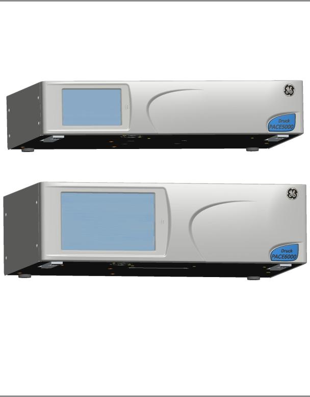
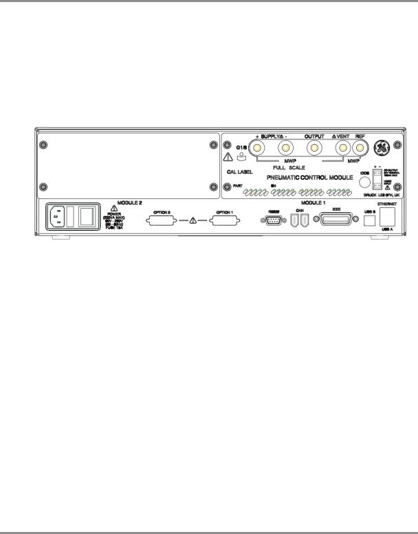
The PACE5000 single-channel and PACE6000 single/dual-channel, Pressure Automated Calibration Equipment measures and controls pneumatic pressures and displays, on a touch-screen, the pressure measurement and controller status. The touch-screen enables selections and settings in both measure and control modes. The instrument can be operated remotely through communication interfaces.
Figure 1-1 PACE5000 General view
Figure 1-2 PACE6000 General view
The rear of the instrument houses all the electrical and pneumatic output and input connections. The electrical connections provide an a.c. power supply, serial and parallel communication interfaces, d.c. output and logic input and output. The system pneumatic controller module contains a positive and negative pressure supply port, an output port, vent port and reference port.
The instrument can be mounted in a standard 19 inch rack system (rack-mount option).
[EN] English |
1 - 1 |
K0443 Revision A |
1 Description
Figure 1-3 PACE5000 Rear view
Figure 1-4 PACE6000 Rear view
Options available are detailed in the product datasheet.
Information and notes on applications (Ref: Reference and Specification, Section 6) or www.gemeasurement.com
K0443 Revision A |
1 - 2 |
[EN] English |

PACE Pressure Controller User Manual
2 Installation
2.1Packaging
Check the contents of the PACE5000/6000 packaging with the list that follows:
Packaging List
i)PACE5000 or PACE6000 Pressure Controller.
ii)Cable, power supply.
iii)User guide and CD (UD-0001) containing the full documentation suite.
iv)Pneumatic Control Module blanking plate (keep this plate for future use).
CAUTIONS
After removing a control module, use a blanking plate to keep the flow of cooling air.
After unpacking an instrument that has been in cold conditions allow time to stabilise and any condensation to evaporate.
2.2Packaging for Storage or Transportation
To store or return the instrument for calibration/repair do the procedures that follow:
1.Pack the instrument (Ref: Reference and Specification, Section 6.8).
2.Return the instrument for calibration/repair complete the return goods procedure (Ref: Reference and Specification, Section 6.8).
Note: The procedure above applies to the pressure control module as a separate item.
2.3Preparation for Use
The instrument can be used as a:
•Free-standing instrument positioned on a horizontal surface.
•Rack-mounted in a standard 19 inch rack using the rack-mount option kit (Ref: Section 2.5, Rack-mount option).
For free-standing instruments, the feet on the front of the base can be used elevate the instrument to a better viewing angle.
Note: Do not obstruct the air cooling outlet on the underside of the instrument and allow a free flow of air around the instrument, especially at high ambient temperatures.
[EN] English |
2 - 1 |
K0443 Revision A |
2 Installation
2.4Pneumatic connections
WARNINGS
TURN OFF THE SOURCE PRESSURE(S) AND CAREFULLY VENT THE PRESSURE LINES BEFORE DISCONNECTING OR CONNECTING THE PRESSURE LINES. PROCEED WITH CARE.
ONLY USE EQUIPMENT WITH THE CORRECT PRESSURE RATING.
BEFORE APPLYING PRESSURE, EXAMINE ALL FITTINGS AND EQUIPMENT FOR DAMAGE. REPLACE ALL DAMAGED FITTINGS AND EQUIPMENT. DO NOT USE ANY DAMAGED FITTINGS AND EQUIPMENT.
DO NOT EXCEED THE MAXIMUM WORKING PRESSURE OF THE INSTRUMENT. THIS EQUIPMENT IS NOT RATED FOR OXYGEN USE.
PARALLEL THREADS MUST BE USED. FEMALE THREAD TYPE IS PARALLEL THREAD TO ISO228/1 (DIN ISO228/1, JIS B0202) G1/8.
TAPERED THREADS NOT ALLOWED.
|
PACE pressure port |
PACE rear |
9 |
panel |
|
|
PACE pressure port |
PACE rear |
8 |
panel |
Parallel threads must be used.
Female thread type is parallel thread to ISO228/1 (DIN ISO228/1, JIS B0202) G1/8
Tapered threads NOT allowed.
K0443 Revision A |
2 - 2 |
[EN] English |
PACE Pressure Controller User Manual
|
|
|
|
Connection |
|
Port |
|
Input |
supply + |
ISO228/1 G 1/8 parallel threads (DIN ISO228/1, JIS B0202) |
|
supply - |
|||
|
|
||
Output |
Output |
ISO228/1 G 1/8 parallel threads (DIN ISO228/1, JIS B0202) |
|
Vent |
|||
|
Reference |
|
Refer to the data sheet for a complete range of adaptors.
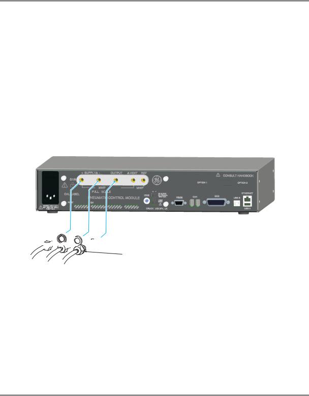
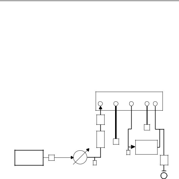
Pressure supply (Ref: Figure 2-1, Pneumatic connections)
1.The pressure supply must be clean, dry gas, nitrogen or air and at the correct pressure, (Ref: Section 6, Reference and Specification).
2.Make sure the user systems can be isolated and vented.
3.Connect pressure and vacuum supplies to the SUPPLY + and SUPPLY - connection ports.
4.Connect the Unit Under Test (UUT) to the required output connection port.
1 Connector
2 Bonded seal


 2
2
1
Figure 2-1, Pneumatic Connections
Note: For systems requiring NPT connections, please order optional NPT adaptors.
[EN] English |
2 - 3 |
K0443 Revision A |
2 Installation
Installation
The safety of any system incorporating the equipment is the responsibility of the assembler of the system.
The instrument requires a positive pressure supply, instruments operating in an absolute range or negative pressure range require a vacuum supply.
A vacuum supply should be used for a fast response for instruments operating near atmospheric pressure.
For dual channel operation two independent pressure and vacuum supplies can be used.
Figure 2-2, Pressure module rear view
Note: When using two pressure modules (Ref: Section 4.9, Pressure module replacement) make sure that:
•The module with the highest pressure rating is fitted to the right hand side Module 1 position as viewed from the rear of the product refer to (Ref: Fig 2-2)
•If two modules have the same pressure rating, make sure that the module with the higher serial number is fitted to the right hand side Module 1 position as viewed from the rear of the product.
Note: All pneumatic connections must comply with the Pressure Equipment Directive (PED) or other regional pressure standards.
Note: When connecting the output ports of two pressure modules together make sure both are either:
•below 70 bar OR
•between 100 to 210 bar.
To prevent over-pressurisation of pneumatic parts and maintain compliance with the PED do not mix categories.
K0443 Revision A |
2 - 4 |
[EN] English |
PACE Pressure Controller User Manual
Supply equipment
Pneumatic supplies should have isolation valves and, where necessary, conditioning equipment.
The positive pressure supply should be regulated to between 110% of the full-scale pressure range and MWP stated on the control module.
To protect the instrument from over-pressure a suitable protection device (such as a relief valve or bursting disc) must be fitted to prevent over pressurization.
On instruments without a negative supply, the positive pressure discharges from the system to atmosphere through the negative supply port. Pipe the negative port to a safe discharge area or fit a diffuser to the negative port.
During system pressure vent operations, the pressure discharges from the system to atmosphere through the negative and vent ports. Pipe both ports to a safe discharge area or fit a diffuser to the negative port.
Pneumatic Connection Examples (Ref: Figures 2-3, 2-4 and 2-5)
The examples that follow show a single channel connection detail, using supply equipment described above.
SUPPLY |
OUTPUT VENT REF |
+ -
1 |
2 |
8 |
7 |
3  4
4
14
5 |
5 |
6
14
9
a
Figure 2-3, Pneumatic Connections without vacuum supply
1) |
Pressure source |
2) |
Conditioner |
3) |
Filter |
4) |
Regulate to between 110% full-scale and MWP |
5) |
Diffuser* |
||
6) |
Unit under test |
7) |
Optional reservoir † |
8) |
Protection device |
9) Optional differential connection |
|
14) Manual external vent valves |
a) Atmosphere |
|
|
|
|
|
[EN] English |
2 - 5 |
K0443 Revision A |
2 Installation
Note: (Ref: Section 6, Reference and Specification) for details of other system components.
SUPPLY |
OUTPUT VENT REF |
+ -
|
3 |
1 |
4 |
2 |
|
|
12 |
11 |
10 |
8 |
|
|
5 |
|
7 |
|
14 |
|
6 |
|
14 |
9 |
|
|
|
|
7 |
a |
|
13 |
|
|
|
Figure 2-4, Pneumatic Connections with vacuum supply
1) |
Pressure source |
2) Conditioner |
3) Filter |
||
4) Regulate to between 110% full-scale and MWP |
5) Diffuser* |
||||
6) |
Unit under test |
7) Optional reservoir † |
8) Protection device |
||
9) |
Optional differential connection |
10) |
Oil mist trap |
||
11) |
Vacuum source |
12) Normally open electrical release valve |
13) |
Check valve ** |
|
14) |
Manual external vent valves |
a) Atmosphere |
|||
Note: The PACE option IO-VAC-SYS Vacuum System Check Valve Kit should be used in the vacuum line mounted near the PACE CM -ve port to exhaust most HP gas directly to atmosphere. The vacuum buffer volume needs to be rated at least to the highest system pressure.
Note: (Ref: Section 6, Reference and Specification) for details of other system components
K0443 Revision A |
2 - 6 |
[EN] English |
PACE Pressure Controller User Manual
|
|
|
SUPPLY |
OUTPUT VENT REF |
|
|
|
|
+ |
- |
|
|
|
|
8 |
|
|
|
|
3 |
|
5 |
|
|
|
|
|
|
|
1 |
2 |
4 |
7 |
|
|
|
|
|
|||
|
|
|
14 |
6 |
|
|
11 |
|
|
14 |
|
|
|
|
|
9 |
|
|
|
|
|
|
|
|
10 |
|
7 |
|
a |
|
|
|
|
13 |
|
|
|
|
|
|
12
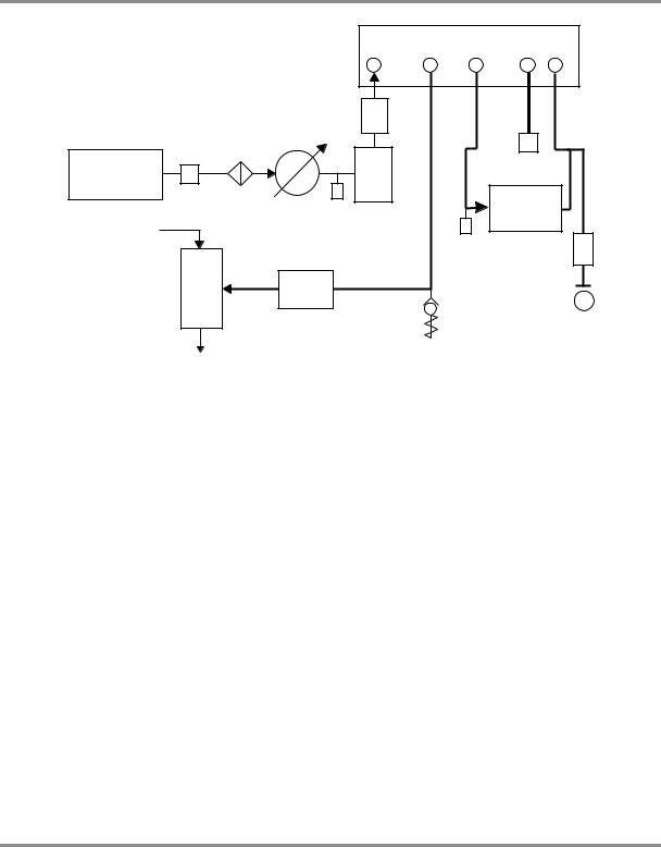
Figure 2-5, Pneumatic Connections with negative gauge pressure generator
1) |
Pressure source |
2) |
Conditioner |
3) |
Filter |
4) |
Regulate to between 110% full-scale and MWP |
5) |
Diffuser * |
||
6) |
Unit under test |
7) |
Optional reservoir † |
8) |
Protection device |
9) Optional differential connection |
a) Atmosphere |
||
10) |
Vacuum generator ‡ |
11) Source pressure (regulated compressed air supply) |
|
12) |
Exhaust to atmosphere |
13) Check valve ** |
14) Manual external vent valves |
Notes: (Ref: Section 6 Reference and Specification) for details of other system components.
*High pressure gas exhaust - depending on pressure range.
**Optional vacuum system kit, allows the -ve port gas to be directly discharged to atmosphere, by-passing the vacuum pump.
†Optimum controller transient response and minimum time to set-point may be degraded if either the pneumatic supply or vacuum system has restricted flow. Installing a reservoir volume, which has larger capacity than the load volume, located in close proximity to the controller supply ports can improve the controller response.
‡Optional negative gauge pressure generator kit.
To protect the control module, for ranges of 70 bar and above from over-pressure a suitable protection device (such as a relief valve or bursting disc) must be fitted to limit the applied supply pressure to below the MWP.
Optional differential connection kit.
[EN] English |
2 - 7 |
K0443 Revision A |

2 Installation
2.5Rack-mount option (Ref: Figure 2-6)
General
There must be enough space at the rear of the instrument for all the cables and pipes. The length of the cables and pipes must allow for the removal and fitment of the instrument. The cooling air of the instrument must not be obstructed. Allow a free flow of air through the equipment rack and around the instrument, especially at high ambient temperatures.
Figure 2-6 Rack-mounting
K0443 Revision A |
2 - 8 |
[EN] English |
PACE Pressure Controller User Manual
Procedure
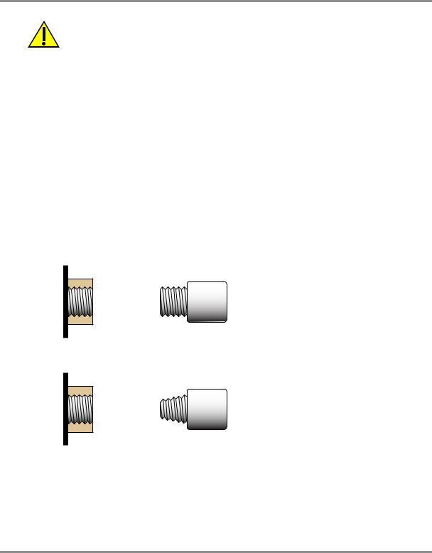
1.Locate bracket in rack assembly .
2.Remove the four M3x10mm countersunk screws from each of the instrument side panels.
3.Locate the two brackets on each side of the instrument.
4.Secure with the four countersunk screws.
5.Support the instrument and connect the cables and pipes.
6.Refer to the electrical connections below before fitting the instrument into the rack.
7.Temporarily locate the two spigots * to each side of the equipment rack.
8.Locate and slide the instrument into the rack.
9.Locate the instrument on the spigots*.
10.Secure the instrument in the equipment rack with two of the screws and washers (supplied).
11.Remove the two spigots* and replace with the remaining two screws and washers (supplied).
2.6Electrical connections
WARNINGS
THE GROUND LEAD OF THE INSTRUMENT MUST BE CONNECTED TO THE AC SUPPLY PROTECTIVE SAFETY GROUND.
ISOLATE THE POWER SUPPLY BEFORE MAKING ANY ELECTRICAL CONNECTIONS TO THE REAR PANEL.
Connecting (Ref: Figure 2.7 Electrical connections)
1.Install an accessible power isolator to use as the disconnecting device in the power supply circuit.
2.For the power input power supply range, Installation Category and VA (Ref: Introduction, General specification table).
Note: The power must be supplied by a fused or overload-protected power supply.
3.Connect the power supply to the instrument.
4.Switch the power supply on.
5.Check that the front panel display shows the power-up sequence (Ref: section 3.2, Power-up sequence).
[EN] English |
2 - 9 |
K0443 Revision A |
2 Installation
1
3
2
1 IEC power connector
2 Fuse carrier
3 Fuse
Figure 2-7 Electrical Connections
Pressure Control Module Input and Output Connectors
24V DC Output @ 100mA maximum
4-way connector: pin “+” |
= |
+24 Vdc |
pin “-” |
= |
0 Vdc |
An integral self-resetting fuse protects this output.
Logic (switch) Input
4-way connector: Input Output
This facility can be used to trigger the instrument from a pressure switch contact during the Pressure Switch Task (Ref Section 3.4, Control Mode).
Connections are not polarised and can be connected either way. Integral opto-isolators protect this input circuit.
This facility can be energised by external SELV compliant equipment.
K0443 Revision A |
2 - 10 |
[EN] English |

PACE Pressure Controller User Manual
Communication Connections (Ref: Fig 2-8 Communication Connectors)
Connect the applicable connectors into the rear panel communications ports and, if appropriate, secure with the captive screws.
Note: Refer to the data sheet for a list of optional communication ports. Refer to the data sheet for a list of standard shipped communication ports.
Set the required parameters in Supervisor Setup/communications menu, (Ref: Section 3.8,
Supervisor set-up).
1
3 |
4 |
5 |
6 |
|
|||
|
|
|
|
|
Figure 2-8, Communication Connectors |
|
1 |
RS232 |
3 IEEE488 |
4 USB B |
5 |
USB A |
6 Ethernet |
|
[EN] English |
2 - 11 |
K0443 Revision A |

2 Installation
RS232 Interface
When using the RS232 interface, a cable must be connected directly from the instrument to a suitable port on the computer in a ‘point to point’ link. The pin connections for the 9-pin D- type, RS232 connector and the relationship between the instrument and the RS232 control signals, together with device interconnection interface is shown in Table 2-1. The instrument is configured as Data Circuit Terminating Equipment (DCE).
Instrument |
Control Line |
Computer/Printer |
||||
|
|
|
|
|
|
|
Instrument |
Connector |
Signal |
RS232 |
Connector Type |
||
|
|
|||||
Function |
9-way |
Direction |
Terminology |
|
|
|
|
D-type |
|
|
9-way |
25-way |
|
|
|
|
D-type |
D-type |
||
|
Pin No. |
|
|
|||
|
|
|
Pin No. |
Pin No. |
||
|
|
|
|
|||
|
|
|
|
|
|
|
RxD (I/P) |
3 |
|
TxD |
3 |
2 |
|
|
|
|
|
|
|
|
TxD (O/P) |
2 |
|
RxD |
2 |
3 |
|
|
|
|
|
|
|
|
GND |
5 |
|
GND |
5 |
7 |
|
|
|
|
|
|
|
|
CTS (I/P) |
7 |
|
RTS |
7 |
4 |
|
|
|
|
|
|
|
|
RTS (O/P) |
8 |
|
CTS |
8 |
5 |
|
|
|
|
|
|
|
|
Pulled |
|
|
RLSD |
|
|
|
high |
1 |
|
1 |
8 |
||
(DCD) |
||||||
internally |
|
|
|
|
||
|
|
|
|
|
||
|
|
|
|
|
|
|
Not |
4 |
|
DTR |
4 |
20 |
|
connected |
||||||
|
|
|
|
|
||
|
|
|
|
|
|
|
Pulled |
|
|
DSR |
|
|
|
high |
6 |
|
6 |
6 |
||
DCE Ready |
||||||
internally |
|
|
|
|
||
|
|
|
|
|
||
|
|
|
|
|
|
|
Equipment |
Connector |
|
Cable Screen |
- |
1 |
|
chassis |
shell |
|||||
|
|
|
|
|||
|
|
|
|
|
|
|
Table 2-1, RS232 Connections
Handshaking connections
Software handshaking use: TXD, RXD and GND.
Hardware handshaking use: TXD, RXD, GND, CTS, RTS and DTR.
K0443 Revision A |
2 - 12 |
[EN] English |
PACE Pressure Controller User Manual
IEEE 488 Interface
The interface complies with IEEE 488 standard.
The IEEE 488 parallel interface connects a computer/controller to one or more PACE instruments and other instruments.
Up to 30 instruments can be connected through a high-speed data bus to the computer/ controller.
Note: The length of each IEEE 488 cable must be less than 3 metres to comply with the EMC requirements (Ref: Section 6, Reference and Specification).
Single Unit Installation (Ref: Figure 2-9)
1.Connect an IEEE 488 connector/cable assembly to the rear panel of the instrument.
2.Connect the other end of the connector/cable assembly to the IEEE 488 connector on the controller/computer.
3.Change the IEEE 488 communication parameters (Ref: Section 6.7, Supervisor set-up).
Multiple Unit Installation (Ref: Figure 2-9)
To install multiple units use stacking plugs to link the first instrument and second instrument as follows.
1Connector to rear panel of first instrument (Ref Illustration).
2Connector from controller/computer (Ref Illustration).
3Connector to rear panel of second instrument (Ref Illustration).
 1
1
2


 3
3
4.Connect the IEEE 488 connector on the controller/computer and the other connector into the next instrument.
5.Repeat this procedure for all the instruments in the system.
6.Use the Supervisor set-up (communications) menu on each instrument to set-up the required communication parameters (Ref: Section 3.8, Supervisor set-up).
[EN] English |
2 - 13 |
K0443 Revision A |
A Revision K0443
- 2 |
IEEE - 9-2 Figure |
14 |
488 |
|
Connection |
English [EN]
ADDRESS 1
IEEE 488 |
|
6 |
DAV (DATA VALID) |
|||
|
||||||
|
7 |
NRFD (NOT READY FOR DATA) |
||||
|
|
|
|
|||
|
|
|
||||
|
|
|
|
8 |
NDAC (NO DATA ACCEPTED) |
|
|
|
|
|
|||
|
|
|
|
5 |
EOI (END OF IDENTIFY) |
|
|
|
|
|
|||
|
|
|
|
9 |
IFC (INTERFACE CLEAR) |
|
|
|
|
|
|||
|
|
ADDRESS 2 |
|
10 |
SRQ (SERVICE REQUEST) |
|
|
|
|
||||
|
|
|
11 |
ATN (ATTENTION) |
||
|
|
|
|
|||
|
|
|
|
17 |
REN (REMOTE ENABLE) |
|
|
|
|
|
|||
|
|
|
1 |
DIO1 |
|
|
|
|
|
|
|||
|
|
|
|
2 |
DIO2 |
|
|
|
|
|
|
||
|
|
|
|
3 |
DIO3 |
DATA/ |
|
|
|
|
|||
|
|
|
|
4 |
DIO4 |
|
|
|
|
|
STATUS |
||
|
|
|
|
13 |
DIO5 |
|
|
|
ADDRESS N (30 maximum) |
|
BAR |
||
|
|
|
14 |
DIO6 |
||
|
|
|
|
|
||
|
|
|
|
15 |
DIO7 |
|
|
|
|
|
|
||
|
|
|
16 |
DIO8 |
|
|
|
|
|
18 |
GND (6) |
|
|
|
|
|
|
19 |
GND (7) |
|
|
|
|
|
|
||
|
|
|
|
20 |
GND (8) |
|
|
|
|
|
|
||
|
|
|
|
21 |
GND (9) |
0V (GND) |
|
|
|
|
|||
|
|
|
|
22 |
GND (10) |
|
|
|
|
|
|
||
|
|
|
|
23 |
GND (11) |
|
|
|
|
|
|
||
|
|
|
24 |
GND |
|
|
|
|
CHASSIS/FRAME |
|
12 |
CHASSIS/FRAME |
|
|
|
|
||||
Installation 2

PACE Pressure Controller User Manual
3Operation
This section contains quick reference charts detailing all the available functions and the setup menu.
3.1Preparation
Make sure the electrical cables and pneumatic pipes comply with the installation requirements (Ref: Section 2, Installation).
Before use do the following:
1.If necessary, do the maintenance task (Ref: Section 4, Maintenance).
2.For bench-top, single instrument operation do the following:
a.Connect the instrument to the electrical supply.
b.Inspect the pneumatic hoses for damage, ingress of dirt and moisture.
3.Before use, the instrument should be tested.
4.Review and become familiar with the procedure before starting a process on a component or system.
Note: The touch-screen can be permanently damaged by sharp objects.
[EN] English |
3 - 1 |
K0443 Revision A |
3 Operation
3.2Power-up sequence
The following sequences of operation shows the instrument display.
Note: The following sequence is an example, the values and selections displayed depend on the range(s) and options enabled in the instrument (Ref: Touch screen areas).
1.Set the power supply to ON:
2.The display shows the power-up sequence.
3.The instrument carries out a self-test.
If the test finds a fault, the display shows an error (Ref: Fault Finding and Testing, Section 5).
4.If the self-test is successful the system enables the touch screen and changes to measure mode.
5.The touch screen shows the measured pressure in the parameters selected in set-up.
6.The instrument is now ready for use.
Note: The PACE 6000 shows a single display (default) this is the left hand pressure control module. Change to dual display in Global Setup/Display.
 1
1
 2
2
 3
3
|
6 |
5 |
|
4 |
|
|
|
Touch screen areas |
|
1 |
Measure set-up |
|
2 |
Control/Measure 3 Nudge up 4 Set-point entry |
5 |
Status (touch to enter control set-up |
6 |
Nudge down |
|
K0443 Revision A |
3 - 2 |
[EN] English |
PACE Pressure Controller User Manual
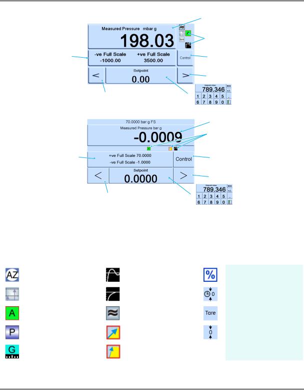
3.3Measure mode
|
PACE5000 |
1 |
|
|
2 |
|
7 |
3 |
|
|
4 |
|
6 |
5 |
|
PACE6000 |
1 |
|
|
|
|
|
2 |
|
7 |
3 |
|
|
4 |
|
6 |
5 |
1 |
Pressure measurement of current selected sensor in current selected pressure measurement units |
|
2 |
Current enabled functions |
3 Control/measure selection |
4 |
Nudge up, changed in control set-up |
5 Current set-point value, change with numeric keys |
6 |
Nudge down, changed in control set-up |
7 Status area, changed in global set-up |
Display Icons
|
|
Auto zero |
|
|
Control mode with overshoot |
|
|
Percentage |
|
|
|
|
|
|
|
||||
|
|
Reference level difference |
|
|
Control mode with no |
|
|
|
Timed zero |
|
|
|
|
|
|
|
|||
|
|
|
|
|
|
|
|||
|
|
(gas head correction) |
|
|
overshoot |
|
|
|
|
|
|
|
|
|
|
|
|
||
|
|
Control mode active |
|
|
Filter pressure reading |
|
|
|
Tare enabled |
|
|
|
|
|
|
|
|||
|
|
|
|
|
|
|
|||
|
|
Control mode passive |
|
|
Linear rate |
|
|
|
Zero |
|
|
|
|
|
|
|
|||
|
|
|
|
|
|
|
|||
|
|
Control mode gauge |
|
|
Maximum rate |
|
|
|
|
|
|
|
|
|
|
|
|
||
|
|
|
|
|
|
|
|
||
|
|
|
|
|
|
|
|
|
|
|
|
|
|
|
|
|
|
|
|
[EN] English |
3 - 3 |
K0443 Revision A |
3 Operation
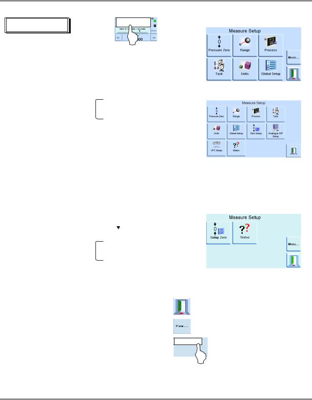
Measure set-up
|
|
|
|
|
|
|
|
|
|
|
|
|
|
|
|
|
|
|
|
|
|
|
|
|
|
|
|
|
|
|
|
|
|
|
|
|
|
|
|
|
|
|
|
|
|
Pressure zero |
- current pressure reading to zero, |
||||||||
|
|
|
|
||||||||||
|
|
|
|
|
|
|
offset stored for current range. |
||||||
|
|
|
|
|
|
|
|||||||
|
|
|
|
|
|
|
|||||||
|
|
|
|
|
|
|
|
|
|
|
|||
|
|
|
|
Range |
- allows selection of available pressure |
||||||||
|
|
|
|
||||||||||
|
|
|
|
|
|
|
ranges. Ê |
||||||
|
|
|
|
|
|
|
|||||||
|
|
|
|
|
|
|
|||||||
|
|
|
|
|
|
|
% |
|
|
|
|
|
|
|
|
|
|
Process |
|
Filter pressure reading |
|||||||
|
|
|
|
|
|||||||||
|
|
|
|
|
|
|
|
Tare |
|||||
|
|
|
|
|
|
|
|||||||
|
|
|
|
|
|
|
|||||||
|
|
|
|
|
|
|
|
|
|
|
|
|
|
|
|
|
|
Task |
|
|
|
|
|
|
|
||
|
|
|
|
|
|
|
|
|
|
|
|||
|
|
|
|
|
|
|
|
|
|
|
|||
|
|
|
|
|
|
|
|
|
|
|
|
|
|
|
|
|
|
|
|
|
|
|
|
|
|||
|
|
|
|
Units |
- select from list of available |
||||||||
|
|
|
|
||||||||||
|
|
|
|
|
|
|
pressure measurement |
||||||
|
|
|
|
|
|
|
|||||||
|
|
|
|
|
|
|
|||||||
|
|
|
|
|
|
|
units. |
||||||
|
|
|
|
|
|
|
|
|
|
|
|||
|
|
|
|
Global set-up |
- see 3.6: |
||||||||
|
|
|
|
||||||||||
|
|
|
|
|
|
|
|
|
|
|
|||
|
|
|
|
|
|
|
|
|
|
|
|
|
|
|
|
|
|
|
|
|
|
|
|
|
|||
|
|
|
|
More |
|
|
- next page: |
|
|
||||
|
|
|
|
|
|
|
|||||||
|
|
|
|
|
|
|
|
Timed |
|||||
|
|
|
|
|
|
|
|
||||||
|
|
|
|
Set-up zero |
|
Auto |
|||||||
|
|
|
|
|
|||||||||
|
|
|
|
|
|
|
|
Tare |
|||||
|
|
|
|
|
|
|
|||||||
|
|
|
|
|
|
|
|||||||
|
|
|
|
|
|
|
|
|
|
|
|
|
|
|
|
|
|
Status |
|
|
|
|
|
|
|
||
|
|
|
|
|
|
|
|
|
|
|
|||
|
|
|
|
|
|
|
|
|
|
|
|
|
|
|
|
|
|
|
|
|
|
|
|
|
|
|
|
PACE5000
PACE6000
ÊAbsolute range selection available when barometric option installed.
Auto-range only available with two-channel instruments.
Exit set-up.
Next page of menu options. Loops from last page to first page.
Stores settings and exits set-up.
K0443 Revision A |
3 - 4 |
[EN] English |

PACE Pressure Controller User Manual
AUTO-RANGE (only available with two-channel instruments)
Note: Not all Auto-Range and task functions are available using the remote communications, this allows more flexibility to the remote programmer.
Controller Off – Increasing Set-point
With both controllers in Measure mode, if a set-point within the range of the lower ranged controller is entered and Control is then selected the lower ranged controller controls to the entered set-point.
With both controllers in Measure mode, if a set-point above the range of the lower ranged controller is entered and Control is then selected, then the range is changed to the higher ranged controller and this then controls to the entered set-point.
Controller Off – Decreasing Set-point
With both controllers in Measure mode, if a set-point within the range of the higher ranged controller is entered and Control is then selected the higher ranged controller controls to the entered set-point.
With both controllers in Measure mode, if a set-point above the range of the lower ranged controller is entered and Control is then selected, then the higher ranged controller will control to this set-point. When the controller is in limits then the range is changed to the lower ranged controller and this then controls to the entered set-point.
Controller On – Increasing Set-point
With the lower ranged controller in Control mode, if a set-point within the range of the lower ranged controller is entered then the lower ranged controller controls to the entered set-point.
If the set-point is increased to above the lower range but still within the higher range then the lower range controller switches off and that the higher range controller switches on and controls to the entered set-point.
Controller On – Decreasing Set-point
With the higher ranged controller in Control mode, if a set-point within the range of the higher ranged controller is entered then the higher ranged controller controls to the entered set-point.
If the set-point is decreased to within the lower range then the higher range controller will control to this set-point. When the controller is in limits then the range is changed to the lower ranged controller and this then controls to the entered set-point.
[EN] English |
3 - 5 |
K0443 Revision A |
Loading...