


 Loading...
DPI 705E/705E-IS
Digital Pressure Indicator
User Manual
Druck.com
Introduction
This user manual covers the DPI 705E / DPI 705E-IS measurement instrument and its associated remote probes, PM 700E / PM 700E-IS for pressure measurement and RTD-INTERFACE / RTD-INTERFACE-IS for temperature measurement.
Unless specifically stated in a section all references to DPI 705E cover both DPI 705E (nonIntrinsically Safe) and DPI 705E-IS (Intrinsically Safe). This also applies to PM 700E, PM 700E-IS and RTD-INTERFACE, RTD-INTERFACE-IS.
RTD-INTERFACE
DPI 705E |
DPI 705E-IS |
PM 700E (Absolute, Gauge) |
PM 700E (Differential) |
|
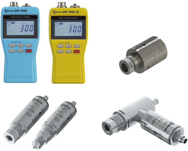
DPI 705E Series Digital Pressure Indicator
The Druck DPI 705E pressure indicator uses a silicon transducer to produce a pressure reading in variouspressure measurement units. These user instructions include the operations for all DPI 705E Pressure Indicators, safety instructions and the requirements for intrinsically safe instruments.
The PM 700E provide a remote pressure sensor function for the DPI 705E to allow more convenient connectionwhendirectconnectionofthehandheld instrumentwouldbeinconvenient.ThePM 700E is a “plug and play” device holding its own calibration data, so it can be used to have multiple pressure range sensors available for immediate use with a single DPI 705E instrument.
The RTD-INTERFACE is a remote interface for use with the DPI 705E or the DPI 620G to allow connection of a PT 100 RTD probe to the instrument for the purpose of measuring temperature.
For all accuracy specifications etc refer to the relevant product datasheet, available for download from Druck.com/essential.
Copyright 2019 Baker Hughes, a GE company, LLC (“BHGE”) — All rights reserved.
137M7122 DPI 705E / DPI 705E IS User Manual–English | i
Commercial and Intrinsically Safe Product versions
The DPI 705E is available as either non-Intrinsically Safe (blue in color) or Intrinsically safe (yellow in color) versions, with case coloring used as well as labeling to indicate the version.
Theremotepressuresensor PM 700Eand the remote RTDinterfaceRTD-INTERFACEareavailable as either non-Intrinsically Safe or Intrinsically safe versions. The outer metal body of the product is marked with its part number and relevant approvals.
Safety
For all safety information on both commercial and Intrinsically Safe versions refer to the Quick Start and Safety Manual provided with the unit and also available for download on Druck.com/essential.
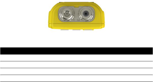
Pressure Connectors and Adaptors
The DPI 705E and PM 700E are fitted with female G1/8 pressure connectors for the main pressure port P1 for ranges 25 mbar - 200 bar(0.36 psi - 2900 psi). For pressures 350 bar-1400 bar(5000 psi - 20000 psi) Autoclavemale pressureconnectorsare used.Themainpressure port P1 is shownonthe left in the picture below.
For differential units/sensors fitted with a reference port a Legris adaptor is fitted giving a 4mm tubing fitting. This is shown as the Ref port on the right in the image below.
Various adaptors are available (either as accessories or configured when ordering) for the G1/8 connection to convert to other standards. Please see datasheet for full details.
Part Code |
Description |
IO-ADAPT-G1/4 |
G1/4 female adaptor |
IO-ADAPT-1/4NPT |
1/4 NPT adaptor |
IO-ADAPT-1/8NPT |
1/8 NPT adaptor |
IO-ADAPT-QF |
Quick-fit hose adaptor |
Copyright 2019 Baker Hughes, a GE company, LLC (“BHGE”) — All rights reserved.
ii | 137M7122 DPI 705E / DPI 705E IS User Manual–English
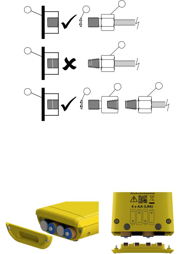
See below for cautions on adaptor and connector fitting:
3 τ;> Xq
: |
; |
0;;: mr pf1 |
4
:
> 4
: ;
1 DPI 705E or PM 700E G1/8 port
2 Bonded seal 110N3018
3ISO 228/1 G1/8
4 NPT thread pressure connector IO-ADAPT-1/4NPT or IO-ADAPT-1/8NPT
5NPT female to G1/8 male adapter part number IO-ADAPT-1/4NPT
Batteries
For compatible battery types refer to Quick Start and Safety Manual provided with the unit and also available for download on Druck.com/essential
The instrument requires 4 x AA/LR6 batteries, fitted as per below image. Use a small Posidrive screwdriver to loosen the screws in the battery compartment cover and fit as per the battery orientation shown on the back of the instrument as illustrated below:
Copyright 2019 Baker Hughes, a GE company, LLC (“BHGE”) — All rights reserved.
137M7122 DPI 705E / DPI 705E IS User Manual–English | iii
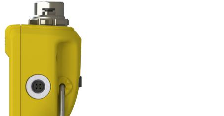
External Sensors
The DPI 705E supports two types of external sensor, both of which connect via a cable into the righthand side of the unit.
 External sensor connector
The sensor must be connected via supplied connection cable (it will not engage correctly if directly pluggedin).The connectorspushin(withpip featuresaligned)thentheouterbodyrotates clockwise to lock the connector in position. Multiple cables may be used in series (i.e. as extenders). Up to a maximum of 10 in series if very long cabled connections are needed.
When an external sensor is connected it is automatically detected and has precedence over the internal sensors. The display shows “


 ” (External Sensor) to show that the reading is from the external sensor. To show a reading from the internal pressure sensor the external sensor must be unplugged.
The external sensor may be either:
•A pressure sensor PM 700E ranging from 25 mbar to 1,400 bar (0.36 psi to 20,000 psi) full-scale.
•A temperature sensor adaptor RTD-INTERFACE which supports a 4-wire PT100 probe.
If a PM 700E pressure sensor is plugged in then the pressure Full-scale will be displayed (only at first plug-in), followed by the calibration due date in days. Normal pressure measurement display will then start.
If an RTD-INTERFACE temperature sensor is plugged in then temperature/resistance full-scale will be displayed (only at first plug-in), followed by the calibration due date in days. Normal resistance or temperature measurement display will then start.
RTD Wiring
The DPI 705E M12 connector is to be connected to an external RTD probe as shown below.
Copyright 2019 Baker Hughes, a GE company, LLC (“BHGE”) — All rights reserved.
iv | 137M7122 DPI 705E / DPI 705E IS User Manual–English
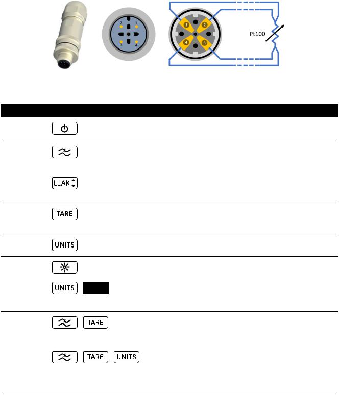
The RTD-INTERFACE is optionally supplied with a field-rewirable M12 connector for customers to connect their own wire-ended RTD's into. This is accessory part number IO-RTD-M12CON. The pin numbering is printed on the rear of the connector body and is reproduced below for clarity.
Customer M12 connector pinout
Connector front |
Connector rear (wiring side) |
|
Controls and Functions
Function Control
Power
Filter
Leak
Tare
Units
Backlight
Alarm
(Press Simultaneously)
Zero
(Press Simultaneously)
Settings
(Press Simultaneously)
Description
Turn the instrument on or off.
Use to get a stable pressure reading over a noisy pressure source.
It has a secondary function as a Back key.
Use to measure pressure leaks over a configurable time interval
It has a secondary function as an OK key.
Set a temporary zero for relative measurements by using the Tare feature.
It has a secondary function as an Increment key.
Change the measurement unit of the instrument It has a secondary function as a Next key.
Turn the instrument backlight on/off.
Set a high and low alarm based on a high/low configurable threshold.
Set the Zero point for your gauge or differential sensor before performing measurement.
Perform Advanced operations such as sensor calibration, configure calibration interval, units, user pin, display lock behavior and factory reset. Also check sensor full-scale values, system date/time, software version and other General settings.
Copyright 2019 Baker Hughes, a GE company, LLC (“BHGE”) — All rights reserved.
137M7122 DPI 705E / DPI 705E IS User Manual–English | v

Display Segments |
|
|
|
|
|
|
|
The DPI 705E display segment is explained below: |
|
|
|
|
|
||
2 |
3 |
4 |
5 |
6 |
7 |
8 |
9 |
1 |
|
|
|
|
|
|
|
18 |
|
|
|
|
|
|
10 |
|
|
|
|
|
|
|
|
17
16 

15
14 


11
|
13 |
|
12 |
1. |
Leak Test Indicator |
2. |
Battery Level Indicator |
3. |
Filter On Indicator |
4. |
External Sensor Functional Indicator |
5. |
Calibration Due Indicator |
6. |
Remote State Indicator |
7. |
Internal Sensor Functional Indicator |
8. |
Lock Indicator |
9. |
Alarm State Indicator |
10. |
Temperature Degree Indicator |
11. |
Resistance (Ohms) Indicator |
12. |
Custom Units Indicator |
13. |
Pressure Units Indicator |
14. |
Tare Indicator |
15. |
Sensor Type Absolute/Gauge Indicator |
16. |
Minimum Symbol Indicator |
17. |
Negative Value Indicator |
18. |
Maximum Symbol Indicator |
Copyright 2019 Baker Hughes, a GE company, LLC (“BHGE”) — All rights reserved.
vi | 137M7122 DPI 705E / DPI 705E IS User Manual–English
Contents
1. |
Basic Functionality |
1 |
|
|
1.1 |
Turn on/off |
1 |
|
1.2 |
Pressure Measurement |
2 |
|
1.3 |
Temperature Measurement |
2 |
|
1.4 |
ZERO |
3 |
|
1.5 |
TARE |
4 |
|
1.6 |
FILTER |
4 |
|
1.7 |
UNITS |
4 |
|
1.8 |
Backlight |
5 |
2. |
Advanced Functionality |
6 |
||
|
2.1 |
Maximum Reading |
6 |
|
|
2.2 |
Minimum Reading |
6 |
|
|
2.3 |
Leak Test |
7 |
|
|
2.4 |
Alarm |
|
8 |
|
|
2.4.1 |
Set High Alarm |
9 |
|
|
2.4.2 |
Set Low Alarm |
11 |
3. |
Settings |
|
13 |
|
|
3.1 |
Advanced Settings |
14 |
|
|
|
3.1.1 |
Adjust Sensor Calibration |
14 |
|
|
3.1.2 |
Calibrate Sensor |
16 |
|
|
3.1.3 |
Set Calibration Date |
18 |
|
|
3.1.4 Set Calibration Due Interval |
18 |
|
|
|
3.1.5 |
Change User Pin |
20 |
|
|
3.1.6 |
Units Lock |
21 |
|
|
3.1.7 |
Lock Display |
22 |
|
|
3.1.8 |
Factory Reset |
23 |
|
3.2 |
General Settings |
24 |
|
|
|
3.2.1 |
Full-scale Value |
25 |
|
|
3.2.2 |
Calibration Due Date |
25 |
|
|
3.2.3 |
Audio |
26 |
|
|
3.2.4 |
Auto shutdown |
27 |
|
|
3.2.5 |
Battery Type |
28 |
|
|
3.2.6 |
Date |
29 |
|
|
3.2.7 |
Time |
31 |
|
|
3.2.8 |
Custom Unit |
32 |
|
|
3.2.9 |
Software Version |
34 |
4. |
Accessories |
|
36 |
|
5. |
Error Codes & Diagnostics |
37 |
||
|
5.1 |
Error Codes |
37 |
|
|
5.2 |
Diagnostics |
38 |
|
Copyright 2019 Baker Hughes, a GE company, LLC (“BHGE”) — All rights reserved.
137M7122 DPI 705E / DPI 705E IS User Manual–English | vii
6. |
Approved Service Centers |
38 |
|
6.1 Return Goods/Material Procedure |
38 |
Copyright 2019 Baker Hughes, a GE company, LLC (“BHGE”) — All rights reserved.
viii | 137M7122 DPI 705E / DPI 705E IS User Manual–English
1. Basic Functionality
1.1 Turn on/off
 INFORMATION
If no date has been previously set, a “


 ” (Date) symbol is
displayed prompting for a system date. Refer to the Section 3.2.6. to set a system date. After the date is set, follow step 3 onwards.
 INFORMATION The externalsensor has precedence over theinternal sensor.
This means that if an external sensor is connected, the instrument will measure from the external sensor by default.
To turn on the unit, press the power button briefly. All the segments illuminate on the LCD Display as shown below.
Upon successful power up, the sequence of events that follow are,
1.The backlight turns on (unless disabled).
2.The battery level is displayed.
3.The positive full-scale of the sensor is briefly displayed.
4.The number of days remaining to the next calibration due date are then briefly displayed.
Copyright 2019 Baker Hughes, a GE company, LLC (“BHGE”) — All rights reserved.
137M7122 DPI 705E / DPI 705E IS User Manual–English | 1
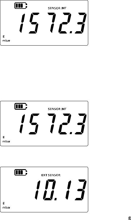
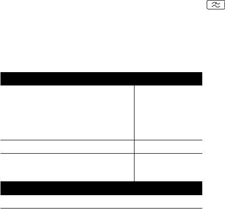
5.The sensor reading screen is then displayed as below. This is the default state or main screen of the instrument.
1.2Pressure Measurement
The DPI 705E can be used to measure pressure from an external pressure source - it does not generate pressure itself.
To measure pressure:
1.Connect an external pressure source to be measured via the P1 pressure port at the top of the instrument.
2.The instrument will display the measured pressure using the internal sensor as shown below.
3.To measure pressure via an external sensor, connect an external sensor via the port on the right side of the instrument.
4.The instrument will then measure pressure using the external sensor as shown below.
Note: The sensor type (absolute or gauge) will be shown on the display as “
 ” or “ ”. Differential sensors are indicated as gauge.
1.3 Temperature Measurement
The DPI 705E can be used to measure temperature using the RTD-INTERFACE. To measure temperature:
1.Connect the RTD-INTERFACE via the port on the right of the instrument, and connect an RTD-PROBE or PT100 to the RTD-INTERFACE.
Copyright 2019 Baker Hughes, a GE company, LLC (“BHGE”) — All rights reserved.
2 | 137M7122 DPI 705E / DPI 705E IS User Manual–English
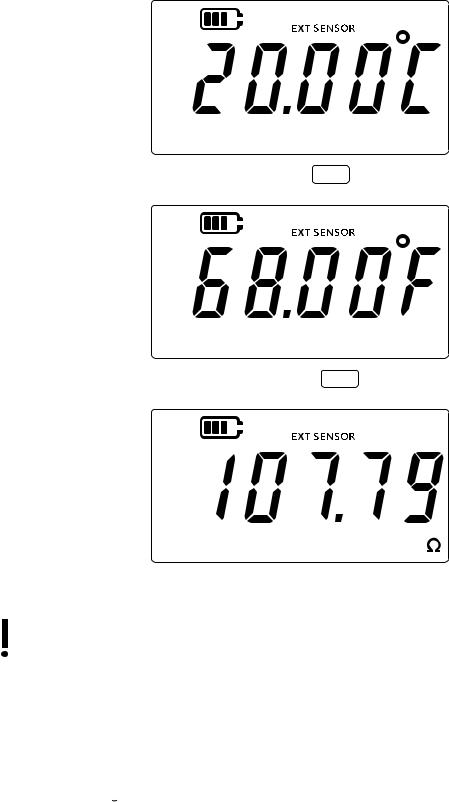
2.The instrument will measure temperature in Degrees Celsius by default as shown below.
3.To change the temperature unit, press the 

 key. The temperature reading is now shown in Degrees Fahrenheit.
4.To change the measurement unit, press the 

 key again. The reading is now shown in Ohms.
1.4ZERO
 CAUTION Zero is a function that causes a non-reversible adjustment of the
zero reading and effectively adjusts the calibration of the sensor. Do not confuse zero with tare - please read both sections if uncertain.
A zero should be performed on a Gauge or Differential pressure instrument before measuring pressure. The zero function is not available on absolute pressure sensors (becauseabsolute vacuum would have to be applied to them to make it valid) and is not available on RTD-Interface.
To perform a zero:
1.Open all pressure ports to atmospheric pressure.
2.Press the  and
and  keys together.
Copyright 2019 Baker Hughes, a GE company, LLC (“BHGE”) — All rights reserved.
137M7122 DPI 705E / DPI 705E IS User Manual–English | 3
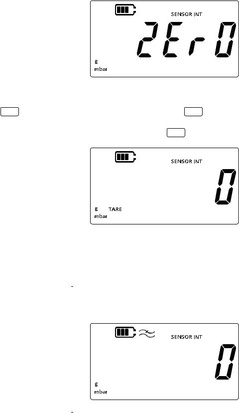
3.The display will briefly show “


 ” (Zero) indicating that the zero function has been successful.
1.5TARE
The tare function allows a temporary offset to make the reading go to zero at the point when the

 key is pressed. This offset is maintained until the
 key is pressed again, or the unit is powered off.
To toggle the tare functionality on or off press the 
 key. If tare is active then “
 ” will be shown on the display as below.
1.6 FILTER
The filter functionality allows a filtered pressure reading by showing a rolling average of last 10 measurements. This will give a more stable reading of a noisy measurement.
To toggle the filter functionality,
1.Press the  key.
key.
2.The current status of the filter function will be displayed.
3.The “ ” (Filter) indication on display means the filter functionality is on. The device will start displaying filtered readings on the display.
4.Press the  key again to turn the filter functionality off. The filter symbol will disappear.
1.7UNITS
To change the pressure units of the display:
Copyright 2019 Baker Hughes, a GE company, LLC (“BHGE”) — All rights reserved.
4 | 137M7122 DPI 705E / DPI 705E IS User Manual–English
1. |
Ensure the sensor reading (home) screen is shown. Otherwise, press the |
key to go |
|
back to the pressure reading screen. |
|
2.Press the  key to go to the next unit until the desired unit of measure is displayed. Note: Some pressure units are not appropriate for some pressure ranges (e.g. mbar units for a 1400 bar sensor, bar for a 25 mbar sensor etc.).
3.The units listed below are supported by DPI 705E.
Pressure Sensor Units:
mbar |
Ib/ft2 |
bar |
kgf/cm2 |
Pa |
kgf/m2 |
hPa |
mmHg (0°C) |
kPa |
mHg (0°C) |
MPa |
inHg (0°C) |
psi |
mmH2O |
RTD Interface Units: |
|
°F |
Ω (Resistance) |
cmH2O (4°C) mH2O (4°C) inH2O (4°C) inH2O (20°C) ftH2O (4°C) ftH2O (20°C)
 Custom Unit
 °C
°C
Custom Unit functionality allows a custom scaling factor for any one of the current units which then automatically gets applied for all units. See Section 3.2.8 for more details.
A custom unit is indicated by a down arrow on the bottom right corner of the display.
1.8 Backlight
The backlight works in 3 modes:
Default mode
• Backlight turns on for a few seconds at any key press (including brief press of backlight key).
Permanently on mode
1.Press and Hold the backlight key on the instrument until the backlight turns on.
2.A double beep is heard if audio is enabled.
3.The backlight should now remain on (regardless of key press).
4.To return the backlight to default mode short press the backlight key.
Permanently off mode
1.Press and Hold the backlight key on the instrument until the backlight turns off.
2.A double beep is heard if audio is enabled.
3.The backlight should now remain off (regardless of key press).
4.To return the backlight to default mode short press the backlight key.
Copyright 2019 Baker Hughes, a GE company, LLC (“BHGE”) — All rights reserved.
137M7122 DPI 705E / DPI 705E IS User Manual–English | 5
2. Advanced Functionality
2.1 Maximum Reading
The maximum reading is the highest read by the instrument since power up. The value will be reset each time the device is turned off.
To view / reset the maximum pressure reading:
1.Ensure the sensor reading screen is shown per below.
2.Press the  key.
key.
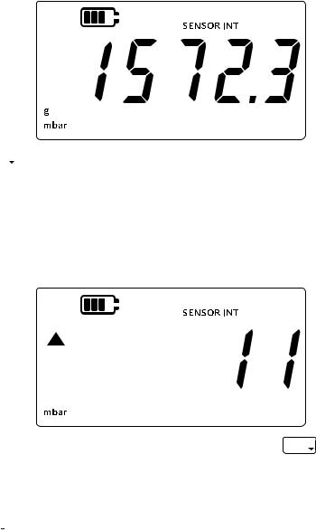
3.The display will now show the maximum recorded reading.
Note:
•The up-arrow on the display indicates that the current reading is the maximum pressure reading. e.g. 11 mbar.
•If there is a dash symbol below the up arrow, it means the reading is negative (not shown in current example).
4.To reset the maximum pressure reading, press and hold the 

 key until a beep sound is heard (if audio is enabled).
5.The reading will now reset, and the unit will immediately start measuring again, but is still only showing the maximum reading on the display - this is effectively Peak Hold mode.
6.Press the  key to exit maximum display mode.
2.2Minimum Reading
The minimum reading is the lowest read by the instrument since power up. The value will be reset each time the device is turned off.
To view / reset the minimum pressure:
Copyright 2019 Baker Hughes, a GE company, LLC (“BHGE”) — All rights reserved.
6 | 137M7122 DPI 705E / DPI 705E IS User Manual–English
Loading...