


Infrastructure
Sensing
Pressure Indicator DPI 142/150
Standard Commands for Programmable Instruments SCPI User Manual K381
g
©2005 General Electric Company. All rights reserved.

i
Introduction
This technical manual provides programming and communication instructions for the Druck DPI 142/150 Pressure Indicator compatible with the requirements of a programming technician.
!Scope
This technical manual contains the communications protocol for the operator of this equipment.
!Software
This technical manual applies to software version 2.
Safety
!The manufacturer has designed this product to be safe when operated using the procedures detailed in this manual. Do not use this product for any other purpose than that stated.
!This publication contains operating and safety instructions that must be followed to make sure of safe operation and to maintain the equipment in a safe
condition. The safety instructions are either warnings or cautions issued to protect the user and the equipment from injury or damage.
!Use qualified* programming technicians and good engineering practice for all procedures in this publication.
"Pressure
Do not apply pressure greater the maximum safe working pressure to the Druck DPI 142/150 Pressure Indicator.
"Maintenance
The Druck DPI 142/150 Pressure Indicator must be maintained using the manufacturer’s procedures and should be carried out by authorised service agents or the manufacturer’s service departments.
"Technical Advice
For technical advice contact the manufacturer or subsidiary.
*A programming technician must have the necessary specialist knowledge of programming, technical knowledge and documentation to carry out the required work on the Druck DPI 142/150 Pressure Indicator.
Associated Druck Documents:
K343 DPI 142 User Manual
K344 DPI 150 User Manual
K382 DPI 142/150 Calibration Manual
Associated Documents:
A beginners Guide To SCPI by Barry Eppler, Published by Addison-Wesley Publishing Company Inc. for Hewlett Packard (ISBN 0-201-56350-9).
K381 Issue No. 1

ii
|
Table of Contents |
|
Preliminary pages |
|
|
Section |
|
page |
Introduction ............................................................................................................................ |
i |
|
Safety |
............................................................................................................................ |
i |
Table of contents (this table) ............................................................................................................................ |
ii |
|
List of Illustrations ............................................................................................................................ |
iv |
|
List of Tables ............................................................................................................................ |
iv |
|
Abbreviations ............................................................................................................................ |
v |
|
Pressure measurement units ............................................................................................................................ |
v |
|
Code Definitions ............................................................................................................................ |
vi |
|
Glossary ............................................................................................................................ |
vii |
|
Pressure unit conversions ............................................................................................................................ |
ix |
|
Section |
|
page |
1 |
INTRODUCTION ....................................................................................................... |
1-1 |
2 |
COMMAND STRUCTURE ................................................................................................... |
2-1 |
2.1 |
Notation ............................................................................................................................ |
2-1 |
2.2 |
Message terminators ............................................................................................................................ |
2-1 |
2.3 |
Program headers ............................................................................................................................ |
2-3 |
2.4 |
SCPI data types ............................................................................................................................ |
2-4 |
2.5 |
Output Queue ............................................................................................................................ |
2-6 |
3 |
COMMAND AND QUERY SUMMARY ............................................................................... |
3-1 |
3.1 |
Command structure ............................................................................................................................ |
3-1 |
|
CALibration ............................................................................................................................ |
3-3 |
|
:CAL:DIOD:ABOR ............................................................................................................................ |
3-3 |
|
:CAL:DIOD:ACC ............................................................................................................................ |
3-4 |
|
:CAL:DIOD:POIN ............................................................................................................................ |
3-5 |
|
:CAL:DIOD:SAMP ............................................................................................................................ |
3-6 |
|
:CAL:DIOD:SAMP:STAR ............................................................................................................................ |
3-7 |
|
:CAL:DIOD:VAL ............................................................................................................................ |
3-8 |
|
:CAL:PRES:ABOR ............................................................................................................................ |
3-9 |
|
:CAL:PRES:ACC ............................................................................................................................ |
3-10 |
|
:CAL:PRES:POIN ............................................................................................................................ |
3-11 |
|
:CAL:PRES:SAMP ............................................................................................................................ |
3-12 |
|
:CAL:PRES:SAMP:STAR ............................................................................................................................ |
3-13 |
|
:CAL:PRES:VAL ............................................................................................................................ |
3-14 |
K381 Issue No. 1

iii
|
|
Table of Contents (contd) |
Section |
|
|
page |
|
|
|
INSTrument ............................................................................................................................ |
3-15 |
|
:INST:CAT ............................................................................................................................ |
3-15 |
|
:INST:SN ............................................................................................................................ |
3-16 |
|
SENSe ............................................................................................................................ |
3-17 |
|
:SENS:PRES ............................................................................................................................ |
3-17 |
|
:SENS:ALT ............................................................................................................................ |
3-18 |
|
:SENS:SPE ............................................................................................................................ |
3-19 |
|
:SENS:MACH ............................................................................................................................ |
3-20 |
|
:SENS:RANG ............................................................................................................................ |
3-21 |
|
SYSTem ............................................................................................................................ |
3-22 |
|
:SYST:ERR ............................................................................................................................ |
3-22 |
|
:SYST:PASS ............................................................................................................................ |
3-24 |
|
:SYST:PASS:CDIS ............................................................................................................................ |
3-25 |
|
:SYST:PASS:STAT ............................................................................................................................ |
3-26 |
|
UNIT ............................................................................................................................ |
3-27 |
|
:UNIT ............................................................................................................................ |
3-27 |
3.2 |
* Standard commands ........................................................................................................................... |
3-29 |
|
*CLS ............................................................................................................................ |
3-29 |
4 |
ERRORS ............................................................................................................................ |
4-1 |
K381 Issue No. 1

iv
List of Illustrations
Figure
page
Figure 1-1 |
System Model ............................................................................................................................ |
1-1 |
Figure 3-1 |
Command and Query Summary ...................................................................................... |
3-2 |
|
|
List of Tables |
Table |
|
|
page |
|
|
4-1 |
Errors -100 to -199 |
............................................................................................................................ 4-1 |
4-2 |
Errors -200 to -299 ................................................................................ |
............................................ 4-2 |
4-3 |
Errors -300 to -400 ................................................................................ |
............................................ 4-2 |
4-3 |
Errors +201 to +212 .................................................................................. |
.......................................... 4-3 |
K381 Issue No. 1

v
Abbreviations
The following abbreviations are used in this manual; abbreviations are the same in the singular and plural.
abs |
Absolute |
|
ASCII |
American Standard Code for Information Interchange |
|
ATE |
Automatic test equipment |
|
e.g. |
For example |
|
etc. |
And so on |
|
Fig. |
Figure |
|
ft |
Foot |
|
g |
Gauge |
|
GPIB |
General purpose interface bus |
|
i.e. |
That is |
|
IEEE 488 |
Institute of Electrical and Electronic Engineers standard 488 data |
|
m |
Metre |
|
max |
Maximum |
|
mbar |
Millibar |
|
min |
Minute or minimum |
|
No. |
Number |
|
qa |
Quasi-absolute |
(combination of barometric and gauge sensor readings) |
RS232 |
Serial communications standard |
|
SCM |
Sensor calibration module |
|
SCPI |
Standard commands for programmable instruments |
|
+ve |
Positive |
|
-ve |
Negative |
|
°C |
Degrees Celsius |
|
°F |
Degrees Fahrenheit |
|
Pressure measurement units
The following units are used in this manual
ATM |
atmosphere |
BAR |
bar |
CMH2O |
centimetres of water at 20°C |
CMHG |
centimetres of mercury |
FTH2O |
feet of water at 20°C |
FTH2O4 |
feet of water at 4°C |
HPA |
hecto Pascals |
INH2O |
inches of water at 20°C |
INH2O4 |
inches of water at 4°C |
INH2O60 |
inches of water at 60°F |
INHG |
inches of mercury |
KG/CM2 |
kilogrammes per square centimetre |
KG/M2 |
kilogrammes per square metre |
KPA |
kilo Pascals |
LB/FT2 |
pounds per square foot |
MH2O |
metres of water |
MHG |
metres of mercury |
MMH2O |
millimetres of water |
MMHG |
millimetres of mercury |
MPA |
mega Pascals |
PA |
Pascals |
PSI |
pounds per square inch |
TORR |
torr |
MBAR |
millibar |
|
|
|
|
K381 Issue No. 1

vi
Code Definitions
The following codes are used in this manual.
ALT |
Altitude |
ACC |
Accept |
CAL |
Calibration |
CAT |
Catalogue |
CLS |
Clear |
COND |
Condition |
CONF |
Configuration |
DIOD |
Diode |
ERR |
Error |
INST |
Instrument |
MACH |
Mach number |
PASS |
Passive |
POIN |
Point |
PRES |
Pressure |
RANG |
Range |
SAMP |
Sample |
SENS |
Sense |
SPE |
Speed |
STAT |
State |
SYST |
System |
UNIT |
Unit of pressure |
VAL |
Value |
K381 Issue No. 1

vii
Glossary
Terminology
The terminology used in this manual is specific and individual interpretation must not be introduced. The terms are defined as follows:
Adjust |
To bring to a more satisfactory state; to manipulate controls, levers, linkages, |
|
etc. to return equipment from an out-of-tolerance condition to an in-tolerance |
|
condition. |
Align |
To bring into line; to line up; to bring into precise adjustment, correct relative |
|
position or coincidence. |
Assemble: |
To fit and secure together the several parts of; to make or form by combining |
|
parts. |
Calibrate: |
To determine accuracy, deviation or variation by special measurement or by |
|
comparison with a standard. |
Check: |
Make a comparison of a measure of time, pressure, temperature, resistance, |
|
dimension or other quality with a known figure for that measurement. |
Disconnect: |
To detach the connection between; to separate keyed or matched equipment |
|
parts. |
Dismantle: |
To take apart to the level of the next smaller unit or down to all removable parts. |
Examine: |
To perform a critical visual observation or check for specific conditions; to test the |
|
condition of. |
Fit: |
Correctly attach one item to another. |
Inspect: |
Review the work carried out by Specialists to ensure it has been performed |
|
satisfactorily. |
Install: |
To perform operations necessary to properly fit an equipment unit into the next |
|
larger assembly or system. |
Maintain: |
To hold or keep in any particular state or condition especially in a state of |
|
efficiency or validity. |
Operate: |
Make sure that an item or system functions correctly as far as possible without |
|
the use of test equipment or reference to measurement. |
Readjust: |
To adjust again; to move back to a specified condition; to bring back to an |
|
in-tolerance condition. |
K381 Issue No. 1

viii
Reconnect: |
To rejoin or refasten that which has been separated. |
Refit: |
Fit an item which has previously been removed. |
Remove: |
To perform operations necessary to take an equipment unit out of the next larger |
|
assembly or system. To take off or eliminate. To take or move away. |
Repair: |
To restore damaged, worn out or malfunctioning equipment to a serviceable, |
|
usable or operable condition. |
Replace: |
Remove an item and fit a new or a serviced item. |
Reset: |
To put back into a desired position, adjustment or condition. |
Service: |
To perform such operations as cleaning, lubricating and replenishing to prepare for |
|
use. |
Test: |
Ascertain by using the appropriate test equipment that a component or system |
|
functions correctly. |
K381 Issue No. 1
ix
Pressure unit conversions
Pressure unit |
Factor (Pascals) |
Pressure unit |
Factor (Pascals) |
|||
|
|
|
|
|
|
|
bar |
|
100000 |
lbf/ft2 |
|
|
47.8803 |
|
|
|
|
|
|
|
lbf/in2 (psi) |
|
6894.76 |
inHg |
|
|
3386.39 |
|
|
|
|
|
|
|
mH2O |
|
9806.65 |
inH2O |
[1] |
|
249.089 |
|
|
|
|
|
|
|
mbar |
|
100 |
ftH2O |
[1] |
|
2989.07 |
kgf/cm2 |
|
98066.5 |
atm |
|
|
101325.0 |
|
|
|
|
|
|
|
kgf/m2 |
|
9.80665 |
pdl/ft2 |
|
|
1.48816 |
|
|
|
|
|
|
|
mmHg |
|
133.322 |
dyn/cm2 |
|
0.1 |
|
|
|
|
|
|
|
|
cmHg |
|
1333.22 |
hbar |
|
|
10000000 |
|
|
|
|
|
|
|
mHg |
|
133322.0 |
tonf/ft2 |
(UK) |
|
107252.0 |
|
|
|
|
|
|
|
mm/H O |
[1] |
9.80665 |
tonf/in2 |
(UK) |
|
15444300 |
2 |
|
|
|
|
|
|
cm/H2O |
[1] |
98.0665 |
inH2O (USA) |
[2] |
248.64135 |
|
N/m2 |
|
1 |
ftH O (USA) |
[2] |
2983.6983 |
|
|
|
|
2 |
|
|
|
hPa |
|
100 |
kp/mm2 |
|
|
9806650 |
|
|
|
|
|
|
|
kPa |
|
1000 |
kp/cm2 |
|
|
98066.5 |
|
|
|
|
|
|
|
MPa |
|
1000000 |
kp/m2 |
|
|
9.80665 |
|
|
|
|
|
|
|
torr |
|
133.322 |
|
|
|
|
|
|
|
|
|
|
|
Table of pressure units and conversion factors
Unit Conversion
To convert FROM pressure VALUE 1 in pressure UNITS 1
TO pressure VALUE 2 in pressure UNITS 2, calculate as follows:
VALUE 2 = |
VALUE 1 x FACTOR 1 |
|
FACTOR 2 |
Note:
The conversion factor for pressure units referenced [1] are calculated for a water temperature of 4°C. Pressure units referenced [2] are calculated for a water temperature of 68°F, these units are normally used in the USA.
K381 Issue No. 1

x
intentionally left blank
K381 Issue No. 1
Druck DPI 142/150 SCPI User Manual |
1 - 1 |
1INTRODUCTION
1.1General
The IEEE 488 and RS232 interfaces of the DPI 142/150 Pressure Indicators provide remote control of the instrument from a suitable computer or controller. The SCPI protocol enables any instrument with a SCPI facility to be controlled using the same commands. The DPI 142/150 Pressure Indicators use a reduced SCPI command set and the defined SCPI syntax.
The following sections describe and define each instrument command used by the DPI 142/150 Pressure Indicators. Each section contains a quick reference structure of the relevant commands.
CALibration
sub-system
SYSTem sub-system
Pressure |
|
SENSe |
|
UNITs |
|
|
|
|
|||
in |
|
|
|
||
|
|
sub-system |
|
sub-system |
|
|
|||||
|
|
|
|
|
|
|
|
|
|
|
|
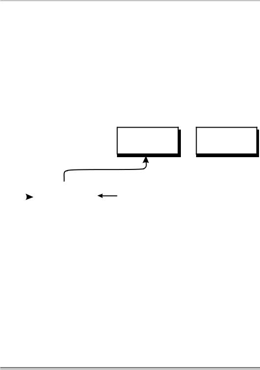
Figure 1-1 System Model
System Model
SCPI starts with a high-level block diagram of the measurement functions of the instrument. Each functional block is broken down into smaller block diagrams. SCPI contains a hierarchy of commands called a subsystem that maps directly to the hierarchy of the block diagram.
K381 Issue No. 1

1 - 2 |
Introduction |
|
|
intentionally left blank
K381 Issue No. 1

Druck DPI 142/150 SCPI User Manual |
2 - 1 |
2COMMAND STRUCTURE
This section describes the structure of the commands and data sent and received by the DPI 142/150 Pressure Indicator.
2.1Notation
All SCPI commands are based on a hierarchical tree structure consisting of key words and parameters. Associated commands are grouped together under a common node in the hierachy.
root |
|
|
|
Level 1 |
|
Level 2 |
||
A |
|
|
|
B |
|
|
|
E |
|
|
|
|
|
|
|
|
F |
|
|
|
|
|
|
|
|
G |
|
|
|
|
C |
|
H |
||
|
|
|
|
|
||||
|
|
|
|
|
|
|
|
|
|
|
|
|
D |
|
|
J |
|
|
|
|
|
|
|
|
|
|
In the command tree the command A is the root command. A tree pointer is used to decode the SCPI commands. At power-up the pointer goes to the root command.
2.2Message Terminators
All SCPI commands are terminated by line feed i.e., either <newline> (ASCII character, decimal 10), EOI for IEEE. After receiving a termination character the tree pointer returns to the root command.
Colon
A colon moves the current path down one level in the command tree, (e.g., the colon in UNIT:PRESSURE specifies PRESSURE the is one level below UNIT). When the colon is the first character of the command, it specifies that the next command is a root level command (e.g., :UNIT specifies that UNIT is a root level command).
K381 Issue No. 1

2 - 2 |
Command Syntax |
|
|
Semicolon
A semicolon separates two commands in the same message without changing the tree pointer.
(e.g., with reference to the tree) :A:B:E;F:G This equivalent to sending three messages
:A:B:E
:A:B:F
:A:B:G
SCPI commands are not case sensitive and may have a short form. In this manual, upper case letter identify the short form.
(e.g.) :INSTrument:SN?
Some nodes can be the default node and these key words are optional when programming the command. The instrument processes the command, with the same effect, with or without the option node. In this manual [] enclose [default notes].
(e.g.) :UNIT[:PRESsure:]? can be sent as
:UNIT:PRESsure?
or
:UNIT?
This gives the pressure units
K381 Issue No. 1

Druck DPI 142/150 SCPI User Manual |
2 - 3 |
2.3Program Headers
Program headers are keywords that identify a command, instruments accept both upper and lower case characters in a program header. There are two types of program header, common command headers and instrument control headers; each header can be a command or a query.
Common Command and Query Headers
The common command and query program header syntax, specified in IEEE 488.2, are defined as follows:
Command
*<PROGRAM MNEMONIC>
Query
*<PROGRAM MNEMONIC>?
Instrument Control Command and Query Headers
The instrument control command and query program header syntax controls and extracts data from the instrument as follows:
Command
:<MNEMONIC> :<MNEMONIC> <PARAMETER>
Query
:<MNEMONIC>?
Queries
Most SCPI commands can be queried. A query is a command header with an attached question mark character (?). On receiving a query command, the current settings for the command are loaded in the output buffer. A query does not affect the operation or set-up of the instrument.
When the parameter contains enumerated character data, both long form and short form are recognised. Querying the command causes the return of data in the short form.
Querying numeric parameters causes the resulting data to be returned in the units selected by the instrument unless specified otherwise.
K381 Issue No. 1
 Loading...