


PRESSURE MEASUREMENT
DPI 610
PORTABLE PRESSURE
CALIBRATOR/INDICATOR
CALIBRATION INSTRUCTIONS
K235
Issue Date: 12th March, 1999
© Druck Limited 1999
This document is the property of Druck Limited and may not be copied or otherwise reproduced, communicated in any way to third parties, nor stored in any Data Processing System without the express written authority of Druck Limited.
Druck Limited, Fir Tree Lane, Groby, Leicester LE6 0FH, England. Tel: (0116) 231 7100 Fax: (0116) 231 7103
K235 Issue 2
Calibration Procedures |
DPI 610 |
DPI 610
PORTABLE PRESSURE CALIBRATOR/INDICATOR
CALIBRATION INSTRUCTIONS
K235
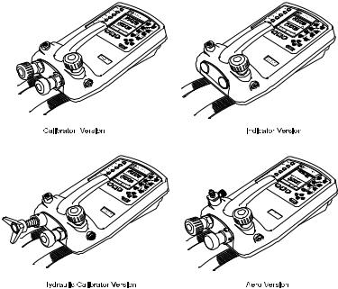
DPI 610 Instrument Versions
© Druck Ltd. 1998
This document is the property of Druck Limited and may not, either in part or whole, be copied or otherwise reproduced, communicated in any way to third parties nor stored in any Data Processing system, without the express written authority of Druck Limited.
1 |
K235 Issue No. 2 |
DPI 610 |
Calibration Procedures |
Calibrator Version
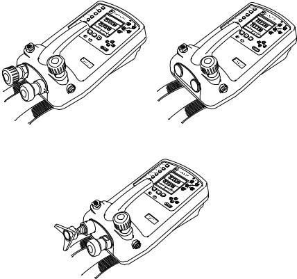
DPI 610 IS Intrinsically Safe Instrument Versions
K235 Issue No. 2 |
2 |
Calibration Procedures |
DPI 610 |
Contents |
|
General ................................................................................................... |
5 |
Introduction ............................................................................................. |
6 |
General Procedures.......................................................................... |
6 |
Calibration Protection ....................................................................... |
6 |
Calibration Check ............................................................................. |
7 |
Calibration Adjustment ...................................................................... |
7 |
Test Equipment ................................................................................. |
7 |
Using The Calibration Menu ............................................................. |
7 |
Change Calibration PIN Number ............................................................ |
8 |
Calibrate Internal Ranges ....................................................................... |
9 |
Pressure ........................................................................................... |
9 |
Voltage Input Range ( 5 Volts) ........................................................ |
10 |
Voltage Input Range (30 Volts) ....................................................... |
12 |
Voltage Input Range (50 Volts) ....................................................... |
14 |
Current Input Range (55 mA) .......................................................... |
16 |
Current Output Range (24 mA) ....................................................... |
18 |
Ambient Temperature Channel ....................................................... |
21 |
Calibrate External Ranges .................................................................... |
22 |
Pressure ......................................................................................... |
22 |
Service ................................................................................................. |
24 |
Approved Service Agents .............................................................. |
24 |
Returned Goods Procedure ........................................................... |
25 |
Safety Precautions (Returned Goods) ...................................... |
25 |
Tables |
|
Table 1 - Internal/External Pressure Transducer Verification ................. |
26 |
Table 2 - Voltage Input Calibration Tolerances (Standard models) ........ |
27 |
Table 3 - Current Input Calibration Tolerances ...................................... |
28 |
Table 4 - Current output Calibration Tolerances .................................... |
29 |
Table 5 - Voltage Input Calibration Tolerances (IS models only) ............ |
27 |
3 |
K235 Issue No. 2 |
DPI 610 |
Calibration Procedures |
INTRINSIC SAFETY CONDITIONS OF USE
This handbook covers the calibration instructions for both standard instruments and intrinsically safe models. Intrinsically safe models are designed to be intrinsically safe when operated in accordance with the BASEEFA Certification document and schedule which is supplied.
BASEEFA Certificate of Conformity No. Ex 99E2002X
BASEEFA being an Approved Certification Body, in accordance with Article 14 of the Council Directive of th European Communities of 18th December, 1975 (76/117/EEC) certifies that the apparatus has been found to comply with harmonised European Standards:
EN 50014: 1992
EN 50020: 1994
and has successfully met the examination and test requirements recorded in confidential report Number
98(C)0818 (ERA Report Ref.3627/856), dated January, 1999
NOTE: For intrinsically safe models, attention is drawn to Pages 4/5 of the Certificate of conformity.
INTRINSICALLY SAFE MODELS SHOULD BE CALIBRATED IN A SAFE AREA
K235 Issue No. 2 |
4 |
Calibration Procedures |
DPI 610 |
General
This publication covers the calibration procedures for DPI 610 Portable Pressure Calibrator/
Indicators and should be read in conjunction with Druck Publications K213 and K239.
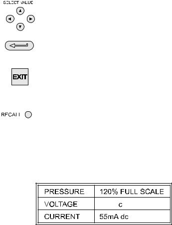
The following key symbols are used in the procedure diagrams which follow and are repeated here (from K213), to allow this supplement to stand alone. Pages 1 to 7 of K213 and K239 detail the operator controls and general information which is relevant to all options of the DPI 610 Instrument.
Shaded cursor keys indicate that a combination of these four keys, Up, Down, Left and Right should be used to (e.g.) enter an alpha numeric value or to select a function.
Indicates the ENTER key. Used to confirm an operation or a selection. Shading indicates key operation.
Exit key, used to clear current menu selection and return to next menu level above current level. Used as an escape key from current operation. Shading indicates key operation.
Hardkey (total 7). Legend beside key symbol indicates function.
Shading indicates key operation.
Maximum Instrument Ratings
The following table shows the maximum measurement ratings of the standard instrument which should not be exceeded. Pressure overrange (120% of FS) is indicated by the pressure display flashing.Voltage or current overrange, causes either the voltage or current display to flash.


 ,[30V dc (IS)]
Note: For the DPI 610 AERO version, when the AERO task is selected,the display flashes if the voltage or current input overranges by 110% of the above maximum values. The pressure display flashes at altitudes below -3000 ft and above
50,000 ft or at airspeeds greater than 600 kts,depending upon the mode selected.
5 |
K235 Issue No. 2 |
DPI 610 |
Calibration Procedures |
Introduction
The instrument is supplied by the manufacturer, complete with calibration certificate(s).
The re-calibration interval will depend on the total measurement uncertainty which is acceptable for a particular application. In order that the instrument remains within the quoted accuracy, it is suggested that it’s calibration be checked at 90 day intervals.
The DPI 610 is a very precise measuring instrument and the test equipment and conditions of test must be suitable for the type of work. The use of a Class A compensated deadweight tester is essential. The tests should be carried out in a controlled environment by a competent, trained person.
If, when the accuracy of the instrument is checked, it is found to fall outside the specification, calibration adjustment can be undertaken to compensate errors.
The manufacturer offers a comprehensive and, if required, NAMAS accredited calibration service.
General Procedures
The following general hints are provided as a guide to calibration procedures.
Do
Use high quality Repeatable and Linear pressure sources and allow adequate stabilisation time before calibration (minimum 1 hour).
Conduct the calibration in a temperature and preferably, humidity controlled environment.
Recommended temperature is 21°C, ±2°C .
Use deadweight testers carefully and away from draughts.
Review and become familiar with the whole calibration procedure before commencing the calibration process.
Ensure that the instrument is NOT set to BASIC mode. The Instrument’s calibration routines are not accessible from this mode. If necessary, use the TASK key to select another mode
(e.g.) ADVANCED.
Calibration Protection
In order to protect against accidental loss,the calibration of this instrument is protected by a PIN number. Initially, this PIN number is set to 4321. To prevent unauthorised access to the calibration routines, it is recommended that this PIN number should be changed at the earliest opportunity(refer to Page 8).
K235 Issue No. 2 |
6 |
Calibration Procedures |
DPI 610 |
Calibration Check
At the chosen interval, the instrument readings should be compared with a known standard. Any deviations between the instrument and the standard should be noted, taking due account of the traceability (accuracy to a National Standard). If these deviations exceed the published tolerance, or any other suitable chosen performance standard, then the user may wish to carry out a calibration adjustment.
It is recommended that measurements be checked at 0, 20, 40, 60, 80 and 100% of full scale on an ascending and descending run. Refer to Tables 1 to 4, pages 27 to 30, for details of test inputs and tolerances.
Calibration Adjustment
If the instrument is operating correctly, only zero and full scale calibration will vary. Any excessive non-linearity or temperature effects indicate a fault. In these circumstances,the instrument should be returned to a qualified service agent (refer to pages 22 and 23).
Test Equipment
The following laboratory standard test equipment will be required for the calibration procedures:-
Instrument |
Calibration |
Calibration |
Range |
Equipment |
Uncertainty |
|
Accuracy |
|
|
|
|
5V Input |
± 30 ppm ± 1 digit |
± 10 ppm ± 5 mV |
|
|
|
30V Input (IS Types) |
± 45 ppm ± 1 digit |
± 11 ppm ± 110 mV |
|
|
|
50V Input |
± 45 ppm ± 1 digit |
± 11 ppm ± 110 mV |
|
|
|
55 mA Input |
± 150 ppm ± 4 digits |
± 100 ppm ± 1 nA |
|
|
|
24 mA Output |
± 150 ppm ± 4 digits |
± 160 ppm ± 1 nA |
|
|
|
Ambient Temp |
± 0.2 °C |
± 0.1°C ± 1 digit |
|
|
|
Pressure Int/Ext |
Class A Deadweight |
< 0.025% |
|
|
|
Using the Calibration Menu
The calibration routines are selected from the Setup menu as detailed on page 8. The calibration routines are not accessible whilst the instrumement is in BASIC mode. If necessary therefore,use the TASK key to select another mode (e.g.) ADVANCED before attempting to access the CALIBRATION mode.
7 |
K235 Issue No. 2 |

DPI 610 |
Calibration Procedures |
To enter the CALIBRATION mode, press SETUP and select CALIBRATE from the menu as shown below.
Use a combination of the cursor keys to enter the PIN number (Initially set to 4321) as shown below. The Up and Down keys enter numerals (0 to 9) or (9 to 0) respectively and the right and left keys shift number position. If the Enter pin prompt disappears before the first digit is entered, press ENTER to re-display.
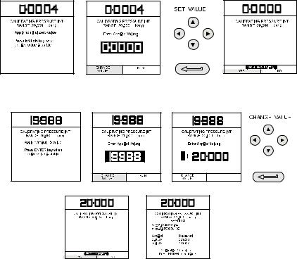
Change Calibration PIN Number
The Calibration PIN number is changed from the Calibration Menu. Use the cursor keys to select CHANGE PIN and proceed as follows.
Note that the new PIN number requires to be entered twice, the second entry being used to verify the change. If the second PIN number entry differs from the first, the PIN number is not changed and the following error message is displayed.
|
|
|
|
|
|
|
|
|
|
|
|
|
|
|
|
|
|
|
|
|
|
|
|
|
|
|
|
|
|
|
|
|
|
|
|
|
|
|
|
|
|
|
|
|
K235 Issue No. 2 |
8 |
|
|
|||||
Calibration Procedures |
DPI 610 |
Calibrate Internal Ranges
Pressure
The following procedure should be adopted for calibrating the internal pressure range.
Note: If calibrating the hydraulic calibrator version, the calibrator must first be primed as detailed on pages 39 to 42 of K213, pages 37 to 41 of K239.
(1)Connect the outlet port of the instrument to a pressure standard.
(2)Allow the instrument’s temperature to stabilise for a minimum of 1 hour.
(3)Switch the instrument on, enter CALIBRATION mode and select INT RANGES from the CALIBRATION menu as shown on Page 8 and then PRESSURE INT.
(4)Apply zero pressure and store the zero point as shown below (e.g.),
(5)Close the vent valve, apply full scale pressure and store the full scale (FS) point as shown below (e.g.),
(6)Press the ENTER key to accept the calibration. Press the EXIT key four times to quit the CALIBRATION and SETUP modes.
(7)Check calibration by applying test pressures detailed in Table 1, Page 27.
9 |
K235 Issue No. 2 |
 Loading...