


GE
Measurement and control
Druck DPI611
Portable Pressure Calibrator
User Manual – K0571
© 2014 General Electric Company. All Rights Reserved. Specifications are subject to change without notice. GE is a registered trademark of General Electric Company. Other company or product names mentioned in this document may be trademarks or registered trademarks of their respective companies, which are not affiliated with GE.
GE
Measurement and control
Revision History
This document supersedes all previously issued versions, providing new or revised information. The most recent publication can be determined by comparing the last three characters at the end of the part number and the date issued.
DPI 611 Portable Pressure Calibrator User Manual
Part Number: K0571
Revision |
Date |
General Description of Changes |
|
Level |
Issued |
||
|
|||
Issue 1 |
13/08/14 |
Initial release |
|
|
|
|
|
|
|
|
|
|
|
|

User Manual |
Druck DPI611 |
Contents
1 INTRODUCTION......................................................................................................................................... |
7 |
||
1.1 |
EQUIPMENT IN THE BOX ........................................................................................................ |
7 |
|
1.2 |
OBSERVANCE OF THE USER MANUAL........................................................................... |
7 |
|
1.3 |
GENERAL SAFETY PRECAUTIONS...................................................................................... |
7 |
|
1.4 |
GENERAL WARNINGS.............................................................................................................. |
8 |
|
1.5 |
ELECTRICAL WARNINGS......................................................................................................... |
9 |
|
1.6 |
PRESSURE WARNINGS......................................................................................................... |
10 |
|
1.7 |
OVERVOLTAGE CATEGORY ................................................................................................ |
11 |
|
1.8 |
PREPARING THE INSTRUMENT........................................................................................ |
11 |
|
1.8.1 |
Initial Checks................................................................................................................... |
11 |
|
1.8.2 |
Install the Battery......................................................................................................... |
12 |
|
1.9 |
PARTS.............................................................................................................................................. |
13 |
|
1.9.1 |
Test Port............................................................................................................................. |
14 |
|
1.9.2 |
Pneumatic Pressure Release Valve.................................................................. |
15 |
|
1.10 |
SELECTOR..................................................................................................................................... |
15 |
|
1.10.1 |
Pump.................................................................................................................................... |
16 |
|
1.10.2 |
Volume Adjuster ........................................................................................................... |
16 |
|
1.11 |
ACCESSORIES:............................................................................................................................ |
17 |
|
1.11.1 |
Carry Case (P/N IO611-CASE-1) .......................................................................... |
17 |
|
1.11.2 |
Rechargeable Battery pack (P/N IO611-BATTERY) ................................. |
17 |
|
1.11.3 |
Mains Adaptor (P/N IO620-PSU)......................................................................... |
17 |
|
1.11.4 |
USB Cable (P/N IO620-USB-PC)........................................................................... |
17 |
|
1.11.5 |
IDOS to USB Converter (P/N IO620-IDOS-USB) ......................................... |
17 |
|
Page 3 of 79 |
[EN] English – K0571 Issue 1 |

User Manual |
Druck DPI611 |
1.11.6 USB to RS 232 Cable (P/N IO620-USB-RS232)........................................... |
17 |
|
1.11.7 Dirt Moisture Trap (P/N IO620-IDT621)........................................................... |
18 |
|
1.11.8 |
Pneumatic Hose........................................................................................................... |
18 |
1.11.9 |
Pressure Adaptor set................................................................................................. |
19 |
1.11.10 Comparator Adaptor (P/N IO620-COMP)................................................ |
19 |
|
1.12 DRUCK DPI611, MODES....................................................................................................... |
20 |
|
1.12.1 |
Power ON.......................................................................................................................... |
20 |
1.12.2 |
Power OFF........................................................................................................................ |
20 |
1.12.3 Power up from Standby Mode............................................................................ |
21 |
|
1.13 NAVIGATION ............................................................................................................................... |
21 |
|
1.13.1 Set Date, Time and Language............................................................................. |
22 |
|
1.13.2 |
Themes............................................................................................................................... |
22 |
1.13.3 |
DRUCK DPI611 Manual ............................................................................................ |
22 |
1.14 SOFTWARE AND FIRMWARE UPGRADES.................................................................. |
22 |
|
1.14.1 |
Viewing Software Revision..................................................................................... |
22 |
1.14.2 |
Upgrading the Software.......................................................................................... |
23 |
1.14.3 Upgrade the Application Software................................................................... |
23 |
|
1.14.4 Upgrade the Operating System and Boot Loader Software. .......... |
23 |
|
1.15 MAINTENANCE.......................................................................................................................... |
24 |
|
1.15.1 |
Cleaning............................................................................................................................. |
25 |
1.15.2 |
Replace the Batteries................................................................................................ |
25 |
1.16 INSTRUMENT RETURN.......................................................................................................... |
25 |
|
1.16.1 |
Returned Material Procedure............................................................................... |
25 |
1.16.2 |
Safety Precautions...................................................................................................... |
25 |
1.16.3 |
Important Notice.......................................................................................................... |
26 |
1.16.4 Instrument Disposal in the European Union.............................................. |
26 |
|
Page 4 of 79 |
[EN] English – K0571 Issue 1 |

User Manual |
Druck DPI611 |
1.16.5 |
For more information contact............................................................................. |
26 |
|
1.17 |
ENVIRONMENT.......................................................................................................................... |
26 |
|
1.18 |
MARKS AND SYMBOLS......................................................................................................... |
27 |
|
2 OPERATIONS............................................................................................................................................ |
28 |
||
2.1 |
PNEUMATIC PRESSURE OPERATIONS......................................................................... |
28 |
|
2.1.1 |
Introduction..................................................................................................................... |
28 |
|
2.1.2 |
Release the Pressure................................................................................................. |
28 |
|
2.1.3 |
Attach/Remove the device under test ........................................................... |
28 |
|
2.1.4 |
Vacuum or Pressure Operation.......................................................................... |
30 |
|
2.2 |
CALIBRATOR OPERATIONS................................................................................................. |
31 |
|
2.2.1 |
Basic Calibrator Operation.................................................................................... |
31 |
|
2.2.2 |
Set the Function Utility Options.......................................................................... |
38 |
|
2.2.3 |
Measurement Display Options............................................................................ |
42 |
|
2.2.4 |
Example Procedures.................................................................................................. |
43 |
|
2.3 |
PRESSURE CALIBRATION..................................................................................................... |
48 |
|
2.3.1 |
Set up a Leak Test ....................................................................................................... |
49 |
|
2.3.2 |
Set the Pressure Module to Zero........................................................................ |
51 |
|
2.3.3 |
Error Indications........................................................................................................... |
51 |
|
2.4 |
MEASURE PRESSURE: IDOS Option............................................................................... |
52 |
|
2.4.1 |
IDOS Option Assembly Instructions ................................................................. |
52 |
|
2.4.2 |
IDOS Function Procedures..................................................................................... |
53 |
|
3 DATA LOGGING OPERATION.......................................................................................................... |
54 |
||
3.1 |
SET-UP............................................................................................................................................ |
55 |
|
3.2 |
OPERATION.................................................................................................................................. |
57 |
|
3.3 |
FILE REVIEW................................................................................................................................ |
57 |
|
3.4 |
FILE MANAGEMENT................................................................................................................ |
58 |
|
Page 5 of 79 |
[EN] English – K0571 Issue 1 |

User Manual |
Druck DPI611 |
3.4.1 |
Transfer.............................................................................................................................. |
58 |
|
3.4.2 |
Erase .................................................................................................................................... |
59 |
|
3.4.3 |
Memory Status.............................................................................................................. |
59 |
|
3.5 |
DATA FORMAT ........................................................................................................................... |
59 |
|
4 DOCUMENTATION................................................................................................................................ |
61 |
||
4.1 |
ANALYSIS ...................................................................................................................................... |
61 |
|
4.2 |
SET-UP............................................................................................................................................ |
62 |
|
4.2.1 Define the Reference Channel ............................................................................ |
62 |
||
4.2.2 Define each Input Channel.................................................................................... |
63 |
||
4.3 |
ANALYSIS FUNCTION............................................................................................................. |
64 |
|
4.4 |
RUN PROCEDURE.................................................................................................................... |
65 |
|
4.4.1 Sequence to Upload and Download file....................................................... |
66 |
||
5 CALIBRATION........................................................................................................................................... |
67 |
||
5.1 |
GENERAL....................................................................................................................................... |
67 |
|
5.2 |
CALIBRATION CHECK ............................................................................................................ |
67 |
|
5.3 |
CALIBRATION ADJUSTMENTS.......................................................................................... |
68 |
|
5.4 |
BEFORE STARTING .................................................................................................................. |
68 |
|
5.5 |
PROCEDURES: CURRENT (measure)............................................................................. |
70 |
|
5.6 |
PROCEDURES: CURRENT (source).................................................................................. |
71 |
|
5.7 |
PROCEDURES: DC mV/Volts (measure)...................................................................... |
72 |
|
5.8 |
PROCEDURES: DC Volts (source) .................................................................................... |
74 |
|
5.9 |
PROCEDURES: PRESSURE INDICATOR........................................................................ |
75 |
|
5.10 |
PROCEDURES: IDOS UPM ................................................................................................... |
76 |
|
6 GENERAL SPECIFICATION................................................................................................................ |
77 |
||
7 MANUFACTURER................................................................................................................................... |
79 |
||
Page 6 of 79 |
[EN] English – K0571 Issue 1 |

User Manual |
Druck DPI611 |
1 INTRODUCTION
The Druck DPI611 is a battery-powered instrument for performing pressure and electrical calibration operations. The Druck DPI611 also supplies the power and user interface functions for all optional items.
1.1EQUIPMENT IN THE BOX
The following items are supplied with the Druck DPI611:
•Standard AA size batteries
•1/8” NPT & BSP pressure adaptors
•Set of four test leads
•Safety and Quick Start Guide
•Stylus
1.2OBSERVANCE OF THE USER MANUAL
This manual contains safety and battery installation information for the Druck DPI611. It is the responsibility of the customer, to make sure that all personnel operating and maintaining the equipment are correctly trained and qualified. Before operating or using the equipment read and obey all sections, including all WARNINGS and CAUTIONS given in the Quick Start Guide.
1.3GENERAL SAFETY PRECAUTIONS
Read and obey all the operator's local health and safety regulations and safe working procedures or practices. When doing a procedure or task.
•Use only the approved tools, consumable materials and spares to operate and maintain the equipment.
•Read and obey all applicable WARNING signs.
Page 7 of 79 |
[EN] English – K0571 Issue 1 |

User Manual |
Druck DPI611 |
•Make sure that:
a)All work areas are clean and clear of unwanted tools, equipment and materials.
b)All unwanted consumable materials are discarded in accordance with local health and safety and environmental regulations.
1.4GENERAL WARNINGS
•It is dangerous to ignore the specified limits for the instrument or its related accessories. This can cause injuries.
•If the equipment is used in a manner not specified by the manufacturer, the protection provided by the equipment may be impaired.
•Do not use the instrument in locations with explosive gas, vapor or dust. There is a risk of an explosion.
•Make sure all equipment is serviceable.
•Use equipment only for the purpose for which it is provided.
•Wear all applicable Personal Protective Equipment (PPE).
•Do not use sharp objects on the touch-screen.
Page 8 of 79 |
[EN] English – K0571 Issue 1 |

User Manual |
Druck DPI611 |
1.5ELECTRICAL WARNINGS
•The DC input to the DPI611 is rated at 5V (+/-5%) 4 Amps.
•External circuits should have appropriate insulation to the mains.
•To prevent electrical shocks or damage to the instrument, do not connect more than 30V CAT I between the terminals or between the terminals and the ground (earth).
•This instrument uses standard AA size batteries. To prevent an explosion or fire do not short circuit.
•The power supply input range to the optional power supply unit is 100 – 260Vac, 50 to 60Hz, 250mA, installation category CAT II.
•When using the optional power supply unit as position the power supply so as not to obstruct the supply disconnecting device.
•Note that the operating and storage temperature range of the optional PSU does not match that of the DPI611. Mains PSU operating temperature range 0°C to +40°C, storage temperature range -40°C to +70°C.
•To make sure the display shows the correct data, disconnect the test leads before power is set to ON or changing to another measure or source function.
•Keep the leads free from all contaminants.
Page 9 of 79 |
[EN] English – K0571 Issue 1 |

User Manual |
Druck DPI611 |
1.6PRESSURE WARNINGS
•Some liquid and gas mixtures are dangerous. This includes mixtures that occur because of contamination. Make sure that the equipment is safe to use with the necessary media.
•It is dangerous to attach an external source of pressure to a DPI611 pressure station. Use only the internal mechanisms to set and control pressure in the pressure station.
•To prevent a dangerous release of pressure, isolate and bleed the system before disconnecting a pressure connection.
•To prevent a dangerous release of pressure, make sure that all the related pipes, hoses and equipment have the correct pressure rating, are safe to use and are correctly attached.
•To prevent damage to the DPI611 calibrator, only use it within the specified pressure limits.
•Do not exceed the maximum pressures stated in the appropriate component manual for the unit under test.
•Reduce pressure at a controlled rate when venting to atmosphere.
•Carefully de-pressurize all pipes to atmospheric pressure before disconnecting and connecting to the unit under test.
•Observe absolute cleanliness when using the instrument.
•Severe damage can be caused if equipment connected to this instrument is contaminated.
Page 10 of 79 |
[EN] English – K0571 Issue 1 |
User Manual |
Druck DPI611 |
•Connect only clean equipment to the instrument. To avoid any contamination, an external Dirt Moisture Trap (See Section 1.11.7) is recommended.
•Always wear appropriate eye protection when working with pressure.
1.7OVERVOLTAGE CATEGORY
The following summary of installation and measurement overvoltage categories are derived from IEC61010-1. The overvoltage categories indicate the severity of overvoltage transients.
|
|
|
|
|
Table 1-1 |
|
|
|
|
|
|
|
Overvoltage |
|
|
Description |
|
|
Category |
|
|
|
|
|
|
|
|
|
|
|
|
|
|
|
|
|
|
|
|
Overvoltage category I has the least severe overvoltage |
|
|
CAT I |
|
transients. Generally CAT I equipment is not designed to |
||
|
|
|
|
be directly connected to the mains supply. Examples of |
|
|
|
|
|
CAT I equipment are process loop powered devices. |
|
|
|
|
|
|
|
|
|
|
|
Overvoltage category II describes an electrical |
|
|
CAT II |
|
installation where typically single phase equipment is |
||
|
|
|
|
connected. Examples of such equipment are appliances |
|
|
|
|
|
and portable tools. |
|
|
|
|
|
|
|
1.8PREPARING THE INSTRUMENT
On receipt of the instrument check the contents in the box, listed in accessories See Section 1.11. It is recommended to retain the box and packaging for future use.
1.8.1Initial Checks
Before you use the instrument for the first time:
•Make sure that there is no damage to the instrument, and that there are no missing items; See Section 1.11.
Page 11 of 79 |
[EN] English – K0571 Issue 1 |
User Manual |
Druck DPI611 |
•Remove the plastic film that protects the display.
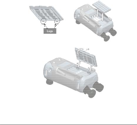
1.8.2Install the Battery
•Remove the battery cover by loosening the captive battery cover fixing screw and lifting the cover upwards.
•Place the batteries in the battery compartment with the correct +/– position.
•Replace the battery cover by pressing the lugs inside the slots (A) and bring down the cover, securing by tightening the fixing screw. (See Figure 1-1).
Figure 1-1 Battery Cover Insert
Page 12 of 79 |
[EN] English – K0571 Issue 1 |
User Manual |
Druck DPI611 |
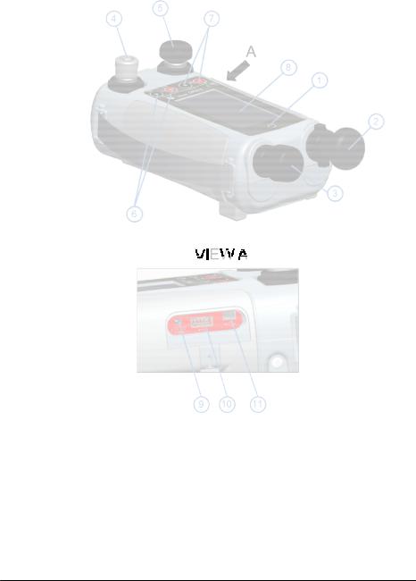
1.9PARTS
Figure 1-2 DPI611 Pressure Calibrator
Page 13 of 79 |
[EN] English – K0571 Issue 1 |

User Manual |
Druck DPI611 |
|
|
|
Table 1-2 |
|
|
|
|
1 |
ON or OFF button. |
|
2 |
Pump mechanism and pressure/vacuum selector. |
|
3 |
Pneumatic volume adjuster. |
|
4 |
Test port: To attach the device under test. |
|
5 |
Pneumatic pressure release valve to release pressure in the |
|
|
system. |
|
6 |
Electrical connectors for: Voltage Measure (V); |
|
|
Current (mA+, mA-); Switch Operation. |
|
7 |
Isolated electrical connectors for: Voltage Source (10 Vo); |
|
|
24 V loop power supply (24 Vo). |
|
8 |
Liquid Crystal Display (LCD): Color display with touch- |
|
|
screen. To make a selection, lightly tap on the applicable |
|
|
display area. |
|
9 |
+5 V DC power input socket. |
|
|
|
|
10 |
USB type A connector for connections to external |
|
|
peripherals (USB flash memory or optional external |
|
|
modules). |
|
11 |
USB mini-type B connector for communication with a |
|
|
computer. |
1.9.1Test Port
Figure 1-3
Test port
To attach the device under test, the test port uses “Quick fit” pressure adaptors;
See Section 1.11. These are easy to remove, change and install; See Section 2.1.3 (Attach/Remove the device under test).
Page 14 of 79 |
[EN] English – K0571 Issue 1 |

User Manual |
Druck DPI611 |
1.9.2Pneumatic Pressure Release Valve
This is a needle point valve that lets you
release the pressure or vacuum, or seal
the system.
 OPEN
OPEN  CLOSE
CLOSE
Figure 1-4
Pressure Release
Valve
1.10SELECTOR
Before you turn the pressure/vacuum selector to + or -, release all the pressure. Sudden high pressure in the pump mechanism can cause damage.
Figure 1-5
Selector
This control sets the operation of the instrument (pressure or vacuum). To prevent a pressure leak, turn it fully clockwise or counterclockwise.
+: Pressure, - : Vacuum
Page 15 of 79 |
[EN] English – K0571 Issue 1 |
User Manual
1.10.1 Pump
Figure 1-6
Pump
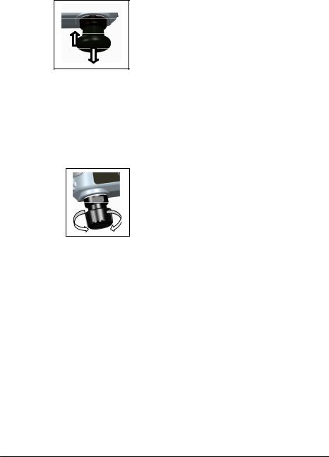
1.10.2 Volume Adjuster
Figure 1-7
Volume Adjuster
Druck DPI611
When you have set the operation to
pressure or vacuum (See Section 1.10),
seal the system (See Section 1.9.2) and
use the pump to set the necessary
pressure or vacuum.
You can then make the last
adjustments with the volume adjuster
(See Section 1.10.2).
This control increases or decreases the
pressure/vacuum.
Before you seal the system (See Section
1.9.2), turn this control to the necessary
position:
•For equal adjustment, turn it to the middle of its range.
•For maximum adjustment, turn it fully clockwise or counterclockwise.
When you have set the necessary pressure or vacuum with the pump (See Section 1.10.1), use the volume adjuster to make the fine adjustments.
Page 16 of 79 |
[EN] English – K0571 Issue 1 |
User Manual |
Druck DPI611 |
1.11ACCESSORIES:
1.11.1 Carry Case (P/N IO611-CASE-1)
A tailored fabric carry case with carrying strap allows the DPI611 to be used without removing it from the case.
1.11.2 Rechargeable Battery pack (P/N IO611-BATTERY)
Use in place of AA cells. The battery pack is charged within the instrument.
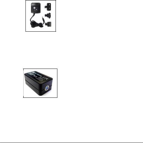
1.11.3 Mains Adaptor (P/N IO620-PSU)
A universal input mains adaptor (Input voltage 100 to 240VAC (50/60Hz) and Mains socket adaptors are provided.
1.11.4 USB Cable (P/N IO620-USB-PC)
It connects the DPI611 to a PC.
1.11.5 IDOS to USB Converter (P/N IO620-IDOS-USB)
It allows connection of an IDOS universal pressure module to the DPI611. USB Cable (P/N IO620-USB-PC) is also required to connect the converter to the DPI611 USB port.
1.11.6 USB to RS 232 Cable (P/N IO620-USB-RS232)
It connects the DPI611 to an RS232 interface.
Page 17 of 79 |
[EN] English – K0571 Issue 1 |
User Manual |
Druck DPI611 |
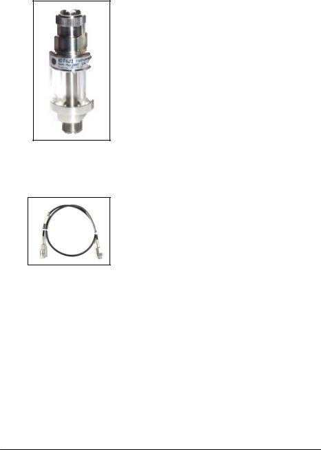
1.11.7 Dirt Moisture Trap (P/N IO620-IDT621)
It prevents contamination of the DPI611 pneumatic system and cross contamination from one device under test to another. The trap connects directly to the pressure port and replicates the DPI611 quick fit connection for compatibility with standard adaptors, adaptor kits and hoses.
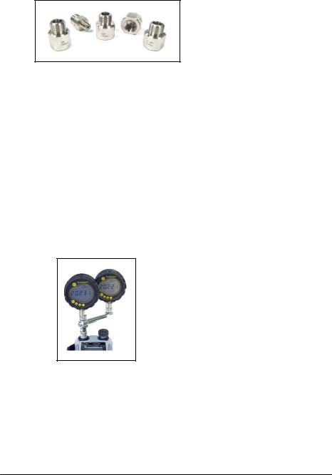
1.11.8 Pneumatic Hose
A high pressure pneumatic hose rated to 400 bar (5800 psi). The hose connects directly to the DPI611 pressure port and replicates the quick fit connection for compatibility with the standard adaptors supplied and the other adaptor kits.
P/N IO620-HOSE-P1: 1m/3,2ft pneumatic adaptor hose
P/N IO620-HOSE-P2: 2m/6.4ft pneumatic adaptor hose
Page 18 of 79 |
[EN] English – K0571 Issue 1 |
User Manual |
Druck DPI611 |
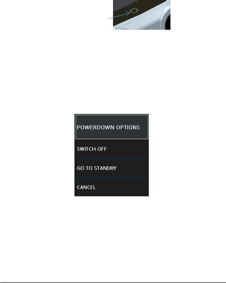
1.11.9 Pressure Adaptor set
A set of test point adaptors to connect the tool-less quick fit DPI611 pressure port or the extension hoses to the device under test.
P/N IO620-BSP: G1/8 male and G1/4 male, G1/4 female, G3/8 female and G1/2 female.
P/N IO620-NPT: 1/8” male and ¼” male, ¼” female, 3/8” female and ½” female.
P/N IO620-MET: 14mm female and 20mm female.
1.11.10 Comparator Adaptor (P/N IO620-COMP)
For greater efficiency, two test devices can be connected at the same time. The adaptor connects to the pressure port of the DPI611 and provides two outlet ports. It is compatible with the standard adaptors supplied and the adaptor kits.
Page 19 of 79 |
[EN] English – K0571 Issue 1 |
User Manual |
Druck DPI611 |
1.12DRUCK DPI611, MODES
1.12.1 Power ON
From OFF – momentarily press the power button until the GE
Logo appears.
Power ON/OFF
Figure 1-8 Power Button
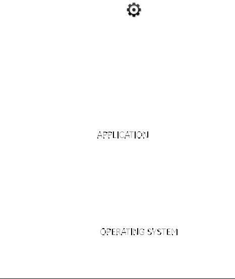
1.12.2 Power OFF
Press and Release the Power Button:
Select SWITCH OFF from the POWERDOWN OPTIONS window displayed.
Figure 1-9 Power Down Options
SWITCH OFF – Full power down of DPI611 – Recommended if unit is not going to be used for several hours (Requires full reboot on next power up).
Page 20 of 79 |
[EN] English – K0571 Issue 1 |
User Manual |
Druck DPI611 |
GO TO STANDBY– DPI611 placed in standby mode – Reduced power consumption from operating mode – recommended if unit is to be inactive for short periods. (DPI611 has fast turn on from STANDBY mode).
CANCEL – Touch CANCEL option if you do not want to Switch Off or Standby the instrument.
1.12.3 Power up from Standby Mode
When powered-up from standby mode the instrument always opens the last screen shown before going into standby mode.
1.13NAVIGATION
On power up the DPI611 displays the Dashboard. The user should select the desired option by touching the appropriate icon. Function screens are navigated by swiping a finger from right to left while touching the screen. List menus are navigated by swiping a finger up and down while touching the screen.
Figure 1-10 Dash Board
Page 21 of 79 |
[EN] English – K0571 Issue 1 |

User Manual |
Druck DPI611 |
1.13.1 Set Date, Time and Language
To access Date, Time and Language menus
Select:
DASHBOARD >>  SETTINGS >> DATE
Note:The DPI611 will maintain the date and time for 30 days after being left without batteries. In case of loss of date and time, replace the batteries, connect the mains adaptor to the DPI611 and keep it turned on for 50 hours to fully recharge the clock battery.
1.13.2 Themes
Two themes are available: Dark and Light; select the correct theme for the light level.
Select:
DASHBOARD >>  SETTINGS >> THEME
1.13.3 DRUCK DPI611 Manual
Select the Help icon on the Dashboard to access the manual. The manual can be downloaded onto a memory stick for viewing or printing on a remote PC.
DASHBOARD >> |
HELP |
1.14SOFTWARE AND FIRMWARE UPGRADES
1.14.1 Viewing Software Revision
The software revisions running on the DPI611 can be viewed by selecting:
DASHBOARD >>  SETTINGS >> STATUS >> SOFTWARE BUILD
Page 22 of 79 |
[EN] English – K0571 Issue 1 |
User Manual |
Druck DPI611 |
Note: If the software revision number is highlighted red then an upgrade is available.
1.14.2 Upgrading the Software
Follow the website instructions to download the files onto a
USB flash memory drive.
www.ge-mcs.com |
|
DASHBOARD >> |
SETTINGS |
>> ADVANCED |
|
Enter the calibration PIN: 5487; Select the button and
continue upgrade with one of these operations.
1.14.3Upgrade the Application Software
1.Copy the ‘AMC’ application folder into the root of a USB flash memory device.
2.Put the USB flash memory drive into the USB type A connector.
3. Select:
4.Follow the on-screen instructions.
1.14.4Upgrade the Operating System and Boot Loader Software.
1.Copy the ‘OS’ folder into the root of a USB flash memory device.
2.Put the USB flash memory drive in the USB type A connector.
3. Select:
Page 23 of 79 |
[EN] English – K0571 Issue 1 |

User Manual |
Druck DPI611 |
4. Follow the on-screen instructions.
Note: The boot loader can only be upgraded as part of an operating system upgrade.
Notes:
•If a mistake is made during upgrade and there are no files to upload, follow the on-screen instructions and complete the procedure.
•When an upgrade completes normally, the initial operation of the touch screen may be slower (a period of approximately 30 seconds).
•To make sure the upgrade completed correctly, use the Status menu.
1.15MAINTENANCE
The DPI611 instrument contains no user serviceable parts and should be returned to a GE service center or an approved service agent for all repairs.
Do not dispose of this product as household waste. Use an approved organization that collects and/or recycles waste electrical and electronic equipment.
For more information, contact our customer service department at www.ge-mcs.com
Page 24 of 79 |
[EN] English – K0571 Issue 1 |
 Loading...