


GE
Sensing
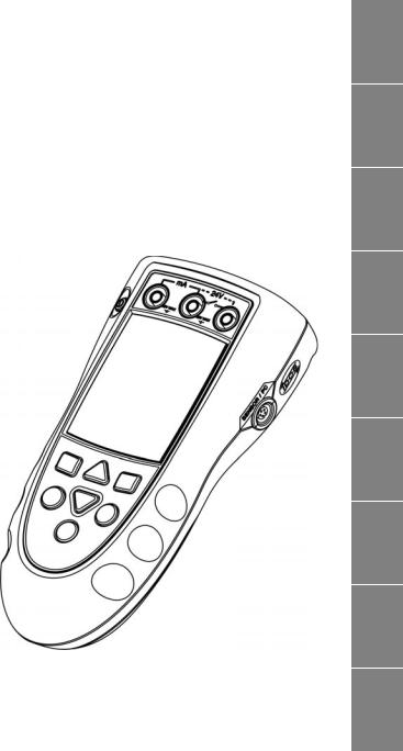
Druck DPI 841/842
Frequency calibrator and Frequency loop calibrator
User manual - K395
[EN] |
English |
[DE] |
Deutsch |
[ES] |
Español |
[FR] |
Français |
[IT] |
Italiano |
[PT] |
Português |
[CN] |
|
[JP] |
|
[RU] |
Русский |

A1 |
|
|
B1 |
|
|
|
|
|
|
|
|
10
A 2
1
9
A 3
8
2 |
|
|
|
7 |
11 |
||||
|
|
|
|
|
|
|
|||
3 |
|
|
|
6 |
|
|
|
|
|
4 |
|
|
|
|
|
|
|
|
|
|
|
|
|
|
5 |
|
|
|
|
|
|
|
|
|
|
|
|
|
|
|
|
|
|
|
|
|
B1 |
|
|
|
|
|
|
|
|
12 |
|
|
|
|
|
|
|
|
|
|
|
|
|
|
|
|
|
|
|
|
|
|
|
A2 |
|
|
|
|
DPI 842 |
|
|
|
|
|
|
13 |
|
|
|
15 |
|
||
|
|
|
|
|
|
||||
|
|
|
|
14 |
|
|
|
|
|
|
|
|
|
|
|
|
|
|
|
|
|
|
|
|
|
|
|
|
|
A3 |
|
|
|
|
|
|
|
|
|
|
|
|
|
|
|
|
|
|
|
19 |
18 |
17 |
16 |
|
27 |
|
|||
20
21
22
23
26
24
25
K395 Issue 3
EN
|
DE |
Druck DPI 841/842 |
|
Frequency calibrator and |
ES |
Frequency loop calibrator |
|
User manual - K395 |
|
|
FR |
IT
PT
CN
JP
RU

Table of Contents |
|
Introduction ......................................................................... |
1 |
Safety ..................................................................................... |
1 |
Marks and symbols on the instrument ................................. |
2 |
To start .................................................................................. |
2 |
Location of items ............................................................................ |
2 |
Items on the display ...................................................................... |
2 |
Prepare the instrument ................................................................ |
2 |
Power on or off ................................................................................ |
3 |
Set up the basic operation ......................................................... |
3 |
Select a task (Measure and/or supply) .................................. |
3 |
Set up the settings ......................................................................... |
4 |
Edit functions .................................................................................... |
4 |
Operation .............................................................................. |
6 |
Frequency connections ............................................................... |
6 |
Communications port connections ........................................ |
6 |
Measure Hz or count pulses ...................................................... |
6 |
Change the output values .......................................................... |
6 |
Supply Hz or pulses ........................................................................ |
7 |
Transmitter calibration ................................................................ |
7 |
mA measurements ........................................................................ |
8 |
Switch test .......................................................................................... |
8 |
UPM Pressure measurements .................................................. |
9 |
Error indications .............................................................................. |
9 |
Maintenance ..................................................................... |
10 |
Clean the unit ................................................................................ |
10 |
Replace the batteries ................................................................. |
10 |
Calibration ......................................................................... |
10 |
Before you start ............................................................................ |
10 |
Procedures (Hz - input/output) .............................................. |
10 |
Procedures (mA input) ............................................................... |
11 |
Procedures (Amplitude output) ............................................. |
11 |
Procedures (IDOS UMM) ............................................................ |
12 |
Specification data ............................................................ |
12 |
General ............................................................................................. |
12 |
Frequency ....................................................................................... |
12 |
Electrical connectors (A2) ......................................................... |
12 |
Customer service ............................................... |
Back cover |
© 2007 General Electric Company. All rights reserved. Trademarks
All product names are trademarks of their respective companies.
Introduction
The DPI 841 Frequency Calibrator and DPI 842 Frequency Loop Calibrator are part of the Druck DPI 800 series of hand held instruments.
The DPI 800 series uses Intelligent Digital Output Sensor (IDOS) technology to give instant plug and play functionality with a range of Universal Measurement Modules (UMM). Example: the Universal Pressure Module (UPM).
The DPI 841/842 include these functions:
|
|
|
|
Function |
DPI 841 |
|
DPI 842 |
Measure/supply a frequency |
|
* |
Yes |
or a pulse count. |
|
|
|
|
|
|
|
Step/Ramp functions |
|
Automatic/Manual |
|
|
|
|
|
Communications port |
|
IDOS or RS232 |
|
|
|
|
|
Language selection |
|
Yes |
|
|
|
||
Measure pressure/Leak test |
** External IDOS UPM |
||
|
|
||
** Snapshot |
Up to 1000 displays with a date/time |
||
|
|
stamp |
|
|
|
|
|
Measure mA |
No |
|
0 - 55 mA |
|
|
|
|
HART® resistor |
No |
|
Yes |
V dc output |
No |
|
24 V |
|
|
|
|
Switch test |
No |
|
Yes |
|
|
|
|
Other functions |
Hold, Maximum/Minimum/Average, |
||
|
Filter, Tare, Scaled values, Backlight, |
||
|
Alarm |
|
|
* Refer to “Specification data”. ** Optional item
Safety
Before you use the instrument, make sure that you read and understand all the related data. This includes: all local safety procedures, the instructions for the UMM (if applicable), and this publication.
WARNING
•It is dangerous to ignore the specified limits for the instrument or to use the instrument when it is not in its normal condition. Use the applicable protection and obey all safety precautions.
•Do not use the instrument in locations with explosive gas, vapor or dust. There is a risk of an explosion.
Continued
K395 Issue 3 |
[EN] English - 1 |
Safety (Continued)
•To prevent electrical shocks or damage to the instrument, do not connect more than 30V between the terminals, or between the terminals and the ground (earth).
•UPM only. To prevent a dangerous release of pressure, isolate and bleed the system before you disconnect a pressure connection.
Before you start an operation or procedure in this publication, make sure that you have the necessary skills (if necessary, with qualifications from an approved training establishment). Follow good engineering practice at all times.
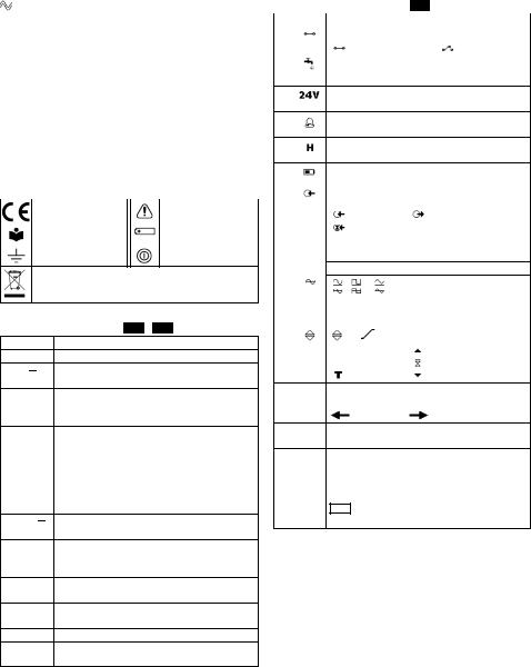
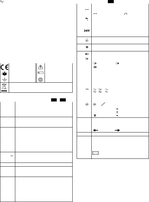
Safety - Marks and symbols on the instrument
|
|
Complies with European |
Warning - refer to the |
Union directives |
manual |
|
|
Read the manual |
Battery |
|
|
Ground (Earth) |
ON/OFF |
Do not dispose of this product as household waste. Refer to “Maintenance”.
To start
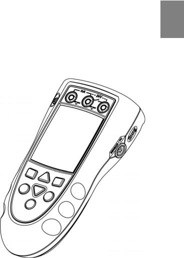
To start - Location of items A1 … A2
Item Description
1.On or off button.
2.Left-hand soft-key. Selects the function above it on
■■ the display (Item 25). Example: Edit
3.Moves back one menu level. ESC Leaves a menu option.
Cancels the changes to a value.
4.▲ Increases or decreases a value. ▼ Highlights a different item.
|
|
|
5. |
HOLD |
Holds the data on the display. To continue, press the |
|
HOLD button again. |
|
|
|
|
6. |
MENU |
Shows the Select Task menu. |
|
Selects or accepts an item or value. |
|
|
OK |
Selects [ ] or cancels [ ] a selection. |
|
|
7.Right-hand soft-key. Selects the function above it on
■■ the display (Item 25). Example: Settings
8.Display. Refer to A3
|
|
9. SENSOR |
Communications port. Use to connect a Universal |
/ PC |
Measurement Module (UMM) or a RS232 cable. |
10.IN Terminals to measure (IN) or supply (OUT) a frequency OUT or a pulse rate. Refer to “Operation”.
11.Connection point for some of the optional accessories. Refer to the datasheet.
12.Battery compartment. Refer to B1.
13., 14., 15. DPI 842 only. Terminals to measure current, to supply 24V source, and to do switch tests.
To start - Items on the display A3
|
|
|
Item |
Description |
|
16. |
DPI 842 only. Task indication for the switch test. |
|
|
= switch closed |
= switch open |
|
UPM only. Task indication for the leak test. |
|
Refer to: Select Task (Table 2/3)
17.DPI 842 only. The loop power supply is on.
Refer to: Select Task (Table 2/3)
18.The measured value satisfies one of the alarm conditions. Refer to: Settings (Table 4)
19.The data on the display is on hold. To continue, press the HOLD button again.
20. |
Shows the battery level: 0 ... 100%. |
|
|
|
|
21. |
Identifies the type of data and the measurement |
|
|
range. |
|
|
= Input |
= Output |
|
= IDOS input |
|
|
Refer to: Select Task (Table 2/3) |
|
|
|
|
22. ... 24. |
The settings applied to the input or output. |
|
22.kHz The units or a specified scale (x:y) - (Table 4/5)
|
|
, |
, |
= Output waveform (Table 5) |
|
|
|
|
|
|
5.0V |
...V |
The input trigger level (Table 4) or the output |
|
|
|
amplitude (Table 5). |
||
|
|
|
||
23. |
|
, ... , |
|
= Output operation (Table 5) |
|
|
|
||
24. |
|
|
|
|
|
|
= Filter |
= Maximum |
|
|
|
|
|
= Average (Table 4) |
|
|
|
= Tare |
= Minimum |
25.A soft-key function. To select an available function, press the soft-key below it. Example:
= Move left |
= Move right |
26.The measured value or values applicable to the task selection.
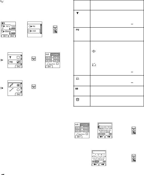
27.The Edit display to set up text labels ( ≤ 6 characters): x:y Scaling (Table 4).
OK = Accept the new text label
Shift = Change the keys: 123ABC or -_+abc = Add a space
BS = Back space (Delete character)
To start - Prepare the instrument
Before you use the instrument for the first time:
•Make sure that there is no damage to the instrument, and that there are no missing items.
•Remove the plastic film that protects the display. Use the tag ( ) in the top right-hand corner.
•Install the batteries (refer to B1). Then re-attach the cover.
2 - [EN] English |
K395 Issue 3 |
To start - Power on or off
To turn the instrument on or off, press (A1 - item [1]). The instrument does a self test and then shows the applicable data.
When the power is off, the last set of configuration options stays in memory. Refer to “Maintenance”.
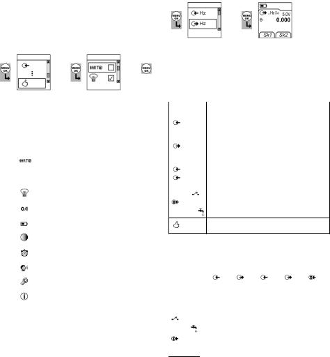
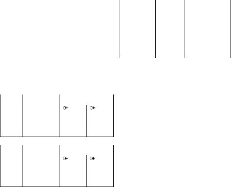
To start - Set up the basic operation
Use the Set Up menu to set up the basic operation of the instrument.
1 |
Menu: |
2 |
3 |
Menu: |
4 |
5 |
|||
Select Task |
Set Up |
||||||||
|
|
|
|
|
|
|
|||
|
|
|
|
|
|
|
|
|
|
|
|
|
▲ |
|
|
▲ |
|
|
|
|
|
|
|
|
|
|
|||
|
|
(Table 2) |
▼ |
|
(Table 1) |
▼ |
|
|
|
|
|
|
|
|
|||||
|
|
|
|
|
|
|
|||
|
|
|
|
|
|
|
|||
|
|
|
|
|
[ ]/[ ] |
||||
If there is additional data for a menu option, select Settings (■ ■) to see the values that are set up. If necessary, adjust the values.
Table 1: Menu options - Set Up
|
|
Options |
Description |
(If applicable) |
|
|
DPI 842 only. To add a series resistor into the mA |
|
circuit. You can then use this instrument together |
|
with a HART® communicator to set up and |
|
calibrate HART® devices. |
|
To select and set up the backlight facility + timer. |
|
Additional data: Select Settings (■ ■) |
|
|
|
To select and set up the power off facility + timer. |
|
Additional data: Select Settings (■ ■) |
|
|
|
To show the battery level (%). |
|
|
|
To set the display contrast (%). |
|
▲ Increases %, ▼ decreases % |
|
To set the time + date. The calibration facility uses |
|
the date to give service and calibration messages. |
|
|
|
To set the language option. |
|
|
|
To calibrate the instrument. |
|
Additional data: Refer to “Calibration”. |
|
|
|
To select and show the applicable status data. |
|
(Software Build, Calibration Due date, Serial |
|
Number, IDOS Information). |
To start - Select a task (Measure and/or supply)
When the instrument is set up (Table 1), use the Select Task menu to select the applicable task.
1 |
Menu: |
2 |
3 |
Display: |
||
Select Task |
Hz output |
|||||
|
|
|
|
|||
|
|
|
|
|
|
|
|
|
|
▲ |
|
|
|
|
|
|
|
|
||
|
|
|
▼ |
|
|
|
|
|
(Table 2/3) |
|
|
Sk1 = Edit |
|
|
|
|
|
|||
|
|
|
|
|||
|
|
|
|
Sk2 = Settings |
||
|
|
|
|
|
||
In Table 2/3, IDOS is a Universal Measurement Module (UMM). If you attach a UMM to the communications port (A1 - item [9]), the Select Task menu shows the applicable IDOS options.
Table 2: Menu options - Select Task
|
|
Options |
Description |
(If applicable) |
|
Hz or |
An input measurement task: |
Pulses |
Hz - Measure the frequency |
|
Pulses - Count the number of pulses |
|
|
Hz or |
An output task: |
Pulses |
Hz - Supply an output frequency |
|
Pulses - Generate a specified number of pulses |
|
|
mA |
DPI 842 only. A mA measurement task. |
|
|
mA(24V) |
DPI 842 only. A mA measurement task + the loop |
|
power supply is on. |
|
DPI 842 only. A switch test. |
IDOS |
UMM only. An IDOS measurement task. |
|
|
|
UPM only. A leak test. |
To set up the way the instrument works.
Additional data: Refer to: Set Up (Table 1).
Table 3 shows all the one and two function operations that are available. If you attach a UMM, you can only use the options that include IDOS.
Table 3: Permitted 1 and 2 function operations
|
|
|
|
|
|
|
|
|
Function |
|
|
|
|
|
|
||
|
|
|
|
Hz |
Hz |
Pulses |
Pulses |
IDOS |
|
|
|
|
|
|
|
|
|
|
|
|
|
(1) |
(1) |
(1) |
(1) |
(1) |
mA |
(1) |
x |
(2) |
x |
x |
(2) |
||
mA(24V) |
(1) |
x |
(2) |
x |
x |
(2) |
||
|
|
|
x |
x |
(2) |
x |
x |
(2) |
|
|
|
x |
x |
x |
x |
x |
(2) |
|
|
|
|
|
|
|
|
|
|
|
IDOS |
(1) |
(2) |
(2) |
(2) |
x |
x |
 = DPI 842 only
K395 Issue 3 |
[EN] English - 3 |
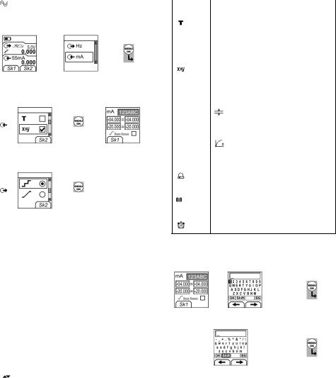
To start - Set up the settings
When the task is set up (Table 2/3), use the Settings menu to adjust the input and/or output operation.
Display: Task |
1 |
Settings selection |
2 |
3 |
|||||||||||
|
Hz + mA |
(If applicable) |
|||||||||||||
|
|
|
|
|
|
||||||||||
|
|
|
|
|
|
|
|
|
|
|
|
|
|
|
|
|
|
|
|
|
|
|
|
|
|
|
|
|
▲ |
|
|
|
|
|
|
|
|
|
|
|
|
|
|
|
|
|
|
|
|
|
■ ■ |
|
|
|
|
|
|
|
|
|
|||
|
|
|
|
|
|
|
|
|
|
▼ |
|
|
|||
|
|
|
|
|
|
|
|
|
|
|
|
|
|
|
|
Sk1 = Start/Stop |
|
|
|
|
|
|
|
|
|
|
|
|
|
||
|
|
|
|
|
|
|
|
|
|
|
|
|
|||
|
|
|
|
|
|
|
|
|
|
|
|
|
|||
Sk2 = Settings |
|
|
|
|
|
|
|
|
|
|
|
|
|||
|
|
Menu: |
|
|
4A |
|
5A |
|
6A |
Settings |
|||||
|
|
Settings |
|
|
|
|
|
x:y |
|||||||
|
|
|
|
|
|
|
|
|
|
|
|
||||
|
|
|
|
|
|
|
|
|
|
|
|
|
|
|
|
|
|
|
|
|
|
▲ |
|
|
|
|
|
|
|
|
|
|
|
|
|
|
|
|
|
|
|
|
|
|
|
|
|
|
|
|
|
|
|
|
|
|
■ ■ |
|
|
|
|
||
|
|
(Table 4) |
|
|
▼ |
|
|
|
|
Sk1 = Edit |
|||||
|
|
|
|
|
|
|
|
|
|
||||||
|
|
|
|
|
|
|
|
|
|
|
|||||
|
|
|
|
|
[ ]/[ |
] |
|
|
|||||||
|
|
Menu: |
|
|
4B |
|
5B |
|
|
|
|
|
|
|
|
|
|
Settings |
|
|
|
|
|
|
|
|
|
|
|||
|
|
|
|
|
|
|
|
|
|
|
|
|
|
||
|
|
|
|
|
|
|
|
|
|
|
|
|
|
|
|
|
|
|
|
|
|
▲ |
|
|
|
|
|
|
|
|
|
|
|
|
|
|
|
|
|
|
|
|
|
|
|
|
|
|
|
(Table 5) |
|
|
▼ |
|
|
|
|
|
|
|
|
|
|
|
|
|
|
|
|
|
|
|
|
|
|
|
|||
|
|
|
|
|
|
|
|
|
|
|
|
|
|
||
|
|
|
|
|
[●]/[ |
] |
|
|
|
|
|
||||
If there is additional data for a menu option, select Settings (■ ■) to see the values that are set up. If necessary, adjust the values. Refer to “Edit functions”.
Table 4: (Part of table) Menu options - Settings (Input)
|
|
|
Options |
Description |
|
(If applicable) |
|
|
|
|
|
... Units |
Frequency Units (Hz input only). To select one of |
|
|
these units: |
|
|
Hz: Range < 1000Hz |
kHz: Range 1 ... 50kHz |
|
Pulses/minute (cpm) |
Pulses/hour (cph) |
... Units |
|
|
UPM only = “Pressure Units” if you select an IDOS |
||
|
task (Table 2/3). Select one of the fixed units of |
|
|
measurement (psi, mbar ... ). |
|
|
|
|
Trigger level |
To set the amplitude at which the instrument |
|
|
senses a frequency signal. Default = 5V. |
|
|
Auto Detect [ ]/[ ]: Set this option to make the |
|
|
instrument calculate the value from the available |
|
|
signal. |
|
|
|
|
|
To include maximum, minimum and average |
|
|
values for the measurement task. |
|
|
|
|
Table 4: (Part of table) Menu options - Settings (Input)
|
|
|||||
Options |
Description |
|||||
(If applicable) |
|
|
|
|
|
|
|
|
|||||
|
To select and set up a tare value for the |
|||||
|
measurement task (a specified value or the reading |
|||||
|
on the display). |
|||||
|
The instrument subtracts a positive tare value, and |
|||||
|
adds a negative tare value. |
|||||
|
Additional data: Select Settings (■ |
|
) |
|
|
|
|
■ |
|||||
|
|
|||||
|
To select and set up a scale of values: One local |
|||||
|
scale for each measurement task (Maximum: 5). |
|||||
|
Additional data (Example 1/2): Select Settings (■ |
|
) |
|||
|
■ |
|||||
|
|
|||||
|
To select and set up the filter values to give a |
|||||
|
smoother output for the measurement task: |
|||||
|
Band as a % of full scale (FS). The filter |
|||||
|
compares each new value with the previous |
|||||
|
value. If the new value is outside the band, it is not |
|||||
|
filtered. |
|||||
|
Low pass filter time constant in seconds. |
|||||
|
Increase the value to increase damping |
|||||
|
factor. |
|||||
|
Additional data: Select Settings (■ |
|
) |
|||
|
■ |
|||||
|
|
|||||
|
To select and set up the alarm values for the |
|||||
|
measurement task (maximum and minimum). |
|||||
|
Additional data: Select Settings (■ |
|
) |
|||
|
■ |
|||||
|
UPM only. Gage sensors or sensors with differential |
|||||
|
operation. A zero correction that makes the |
|||||
|
instrument read zero at local pressure. |
|||||
|
|
|||||
|
Leak Test only. To set an applicable period for the |
|||||
|
leak test (Hours:Minutes:Seconds). |
|||||
To start - Edit functions
Example 1) Set up a label for x:y Scaling = %.
Settings |
1 |
Edit |
|
2 |
|
|
|
Edit |
3 |
||||
x:y |
|
|
|
|
|||||||||
|
|
|
|
|
|
|
|
|
|
|
|
|
|
|
|
|
|
|
|
|
|
|
|
|
|
|
|
|
|
|
|
|
▲ |
|
|
|
|
|
|
||
|
|
|
|
|
|
|
|
|
|
|
|||
|
|
|
|
|
|
|
|
|
|
Shift |
|
|
|
|
■ ■ |
|
|
▼ |
|
|
|
||||||
Sk1 = Edit |
|
|
A3 - item [27] |
■ ■ |
|
|
|
|
|
|
|||
|
|
|
|
|
|
|
|
|
|
|
|||
|
|
|
|
|
|
|
|
|
|
|
|||
|
|
|
Edit |
... |
|
|
Edit |
4 |
|
5 |
|||
|
|
|
|
|
|
|
|
|
|
|
|
|
|
|
|
|
|
%_ |
|
|
|
|
|
|
▲ |
|
|
|
|
|
|
|
|
|
|
|
|
|
|||
|
|
|
|
|
|
OK |
|
▼ |
|
||||
|
A3 - item [27] |
|
|
|
|
|
|
|
■ ■ |
|
|||
|
|
|
|
|
|
|
|
|
|
|
|||
|
|
|
|
|
|
|
|
|
|
|
|||
4 - [EN] English |
K395 Issue 3 |
Example 2) Set up values for x:y Scaling = 0 to 100%.
Settings |
1 |
Settings |
2 |
Edit |
3 4 |
|||
x:y |
x:y |
|||||||
|
|
|
|
|
|
|||
|
|
|
|
|
|
|
|
|
|
▲ |
|
|
|
|
▲ |
|
|
|
|
|
|
|
|
|||
|
|
|
|
|
|
|
||
|
|
■ ■ |
|
▼ |
|
|||
|
▼ |
|
|
|
||||
|
|
|
|
|
■ ■ |
|
||
|
|
|
|
|
|
|
||
Sk1 = Edit |
|
|
|
|
|
|
|
|
|
|
|
|
|
|
|
||
= Flow scaling (mA, pressure only)
Table 5: (Part of table) Menu options - Settings (Output)
|
|
|
|
Options |
Description |
|
|
Hz |
|
|
|
|
|
||
... Units |
Frequency Units. To select one of these units: |
||
|
Hz: Range < 1000Hz |
kHz: Range 1 ... 50kHz |
|
|
Pulses/minute (cpm) |
Pulses/hour (cph) |
|
Amplitude |
To set the amplitude and the mode of the output |
||
|
signal. Amplitude = 5V (Default). |
||
|
Bipolar mode [ ]/[ ]: Set this option to make the |
||
|
signal pass thru zero. |
|
|
|
= Unipolar |
|
= Bipolar |
|
|
||
Waveform |
To set the waveform for the output signal: |
||
|
, , |
= Sine, square, or triangle |
|
To select and set up a value for the “Nudge” output. Example: 0.010 kHz increments.
Additional data: Select Settings (■ ■)
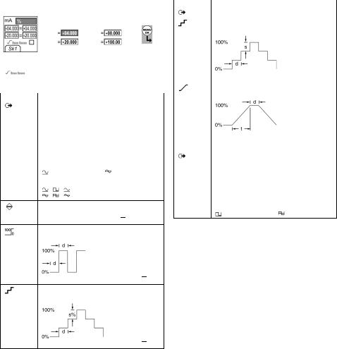
To select and set up values for the “Span Check” output. Example output cycle:
This cycle repeats automatically.
Additional data (Table 6): Select Settings (■ ■)
% Step To select and set up values for the “% Step” output. Example output cycle:
Auto Repeat - Optional
Additional data (Table 6): Select Settings (■ ■)
Table 5: (Part of table) Menu options - Settings (Output)
|
|
|
|
|
Options |
Description |
|
|
|
Hz |
|
|
|
|
|
|
|||
... Step |
To select and set up values for the “Defined Step” |
|||
|
output. Example output cycle: |
|||
|
|
Auto Repeat - Optional |
||
|
Additional data (Table 6): Select Settings (■ |
|
) |
|
|
■ |
|||
|
|
|||
|
To select and set up values for the “Ramp” output. |
|||
|
Example output cycle: |
|||
|
|
Auto Repeat - Optional |
||
|
Additional data (Table 6): Select Settings (■ |
|
) |
|
|
■ |
|||
Options |
Description |
|
|
|
Pulses |
|
|
|
|
|
|
|||
|
Counts: To set the total number of output pulses. |
|||
|
Rate: To set the frequency of the output. |
|||
|
Amplitude: To set the amplitude of the output |
|||
|
signal. Amplitude = 5V (Default). |
|||
|
Bipolar mode [ ]/[ |
]: Set this option to make the |
||
|
signal pass thru zero. |
|||
|
= Unipolar |
= Bipolar |
||
Table 6: Additional data for Settings (Output):
|
|
Item |
Value |
Span Check |
|
Low (0%) |
Set the 0% value. |
High (100%) |
Set the 100% value. |
Dwell (d) |
Set the period (Hours:Minutes:Seconds) between |
|
each change in value. |
|
|
% Step |
Low (0%), High (100%), Dwell (d): As above. |
Step Size (s) ... |
Set the change in value for each step as a |
% |
percentage of the full-scale range (High - Low). |
|
|
Defined Step |
Low (0%), High (100%), Dwell (d): As above. |
Step Size (s) |
Set the change in value for each step as a |
|
frequency value. |
|
|
Ramp |
Low (0%), High (100%), Dwell (d): As above. |
Travel (t) |
Set the period (Hours:Minutes:Seconds) to go from |
|
the Low (0%) value to the High (100%) value. |
|
|
|
|
Auto Repeat |
If applicable, select this item to repeat a cycle |
|
continuously. |
|
|
K395 Issue 3 |
[EN] English - 5 |
Operation
This section gives examples of how to connect and use the instrument. Before you start:
•Read and understand the “Safety” section.
•Do not use a damaged instrument.
Operation - Frequency connections
To prevent instrument errors, make sure that the frequency connections (A1-item [10]) are correct.
Operation - Communications port connections
Use the communications port (A1 - item [9]) to attach an IDOS Universal Measurement Module (UMM).
When you attach the cable from a UMM (Figure 7/8), the instrument automatically changes the menus to give you all the applicable options (Table 2/3).
Operation - Measure Hz or count pulses
To measure Hz or count pulses:
1.Connect the instrument (Figure 1) and, if necessary, adjust the Set Up (Table 1).
2.Select a Hz or Pulses input task from Select Task (Table 2/3) and, if necessary, adjust the Settings (Table 4).
3.For Pulses, use Start/Stop (■ ■) to start and stop the count. The display shows the time (hh:mm:ss) since you started the count.
Pulses
|
|
|
|
|
|
Settings |
Start |
Settings |
|||
a) Hz |
b) Pulses |
||||
Figure 1: Example configuration - To measure Hz or count Pulses
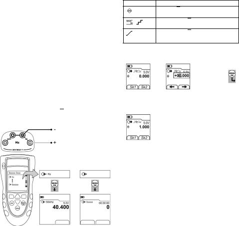
Operation - Change the output values
When the output operation is set up (Table 5), use one of these procedures to change the output values:
Table 7: Procedures to change the output
Output Procedure
Select Edit (■ ■) and/or use the ▲ ▼ buttons. See the example below.
,Select Start/Stop (■ ■) or use the ▲ ▼ buttons to make the step changes manually.
,Select Start/Stop (■ ■).
 Pulses
Example procedure (“Nudge” output):
Display: |
1 |
|
Edit |
2 |
|
3 |
Edit |
4 |
|||||
Hz output |
|
|
|||||||||||
|
|
|
|
|
|
|
|
|
|
|
|
|
|
|
|
|
|
|
|
|
|
|
|
|
|
|
|
|
|
|
|
|
|
|
|
|
|
▲ |
+01.000 |
|
|
|
|
|
|
|
|
|
|
|
|
|
|||
|
■ ■ |
|
|
|
|
■ ■ |
|
||||||
|
|
|
|
|
▼ |
|
|||||||
Sk1 = Edit |
|
|
|
|
|
|
|
|
|
|
|
|
|
|
|
|
|
|
|
|
|
|
|
|
|
|
|
|
|
|
|
|
|
|
|
|
|
|
|
|
|
Sk2 = Settings |
|
|
|
|
|
|
|
|
|
|
|
|
|
Display: |
5 |
|
6 |
|
|
|
|
|
|
|
|
||
Hz output |
|
|
|
|
|
|
|
|
|
||||
|
|
|
|
|
|
|
|
|
|
|
|
|
|
|
|
|
|
|
|
|
|
|
|
|
|
|
|
|
▲ |
1.010 |
|
▲ |
1.020 |
|
|
|
|
|
|
||
|
▼ |
|
▼ |
|
|
|
|
|
|
||||
|
|
|
|
|
|
|
|
|
|
|
|||
|
|
|
|
|
|
|
|
|
|
|
|||
|
|
|
Increment |
= 0.010 |
|
|
|
|
|||||
|
|
|
|
|
(Table 5) |
|
|
|
|
||||
6 - [EN] English |
K395 Issue 3 |
Operation - Supply Hz or pulses
To supply Hz or pulses:
1.Connect the instrument (Figure 2) and, if necessary, adjust the Set Up (Table 1).
2.Select a Hz or Pulses output task from Select Task (Table 2/3) and, if necessary, adjust the Settings (Table 5).
For Pulses, the display shows the time (hh:mm:ss) to complete the count at the specified rate.
3.Supply the output values to the system (Table 7).
Pulses
Pulses
|
|
|
|
|
|
|
Edit |
Settings |
Start |
Settings |
|||
a) Hz |
|
b) Pulses |
||||
Figure 2: Example configuration - To supply Hz or Pulses
Operation - Transmitter calibration
DPI 842 only. To calibrate a transmitter:
1.Connect the instrument (Figure 3/4) and, if necessary, adjust the Set Up (Table 1).
2.Select the applicable calibration task from Select Task (Table 2/3) and, if necessary, adjust the Settings (Table 4/5).
3.Supply the output values to the system (Table 7).
Maximum: 30V
Edit Settings
Figure 3: Example configuration - Transmitter calibration with external loop power
Edit Settings
Figure 4: Example configuration - Transmitter calibration with internal loop power
K395 Issue 3 |
[EN] English - 7 |
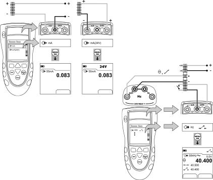
Operation - mA measurements
DPI 842 only. To measure a current:
1.Connect the instrument (Figure 5) and, if necessary, adjust the Set Up (Table 1).
2.Select the applicable mA input task from Select Task (Table 2/3) and, if necessary, adjust the Settings (Table 4).
Maximum: 30V
3. Supply the output values to the system (Table 7).
•Example - “Nudge” output.
a.Use Edit (■ ■) to set a value less than the switch value.
b.Use the ▲ ▼ buttons to change the value in small increments.
•Example - “Ramp” output.
a.Set “High” and “Low” values that are applicable to the switch value (Table 6). Then, to get an accurate switch value, set a long “Travel” period.
b.Use Start/Stop (■ ■) to start and stop the “Ramp” cycle.
4.If necessary, supply the output values in the opposite direction until the switch changes condition again.
The display shows the applicable values to open and close the switch.
5.To do the test again, press ESC to reset the values.
|
|
|
|
|
|
|
Settings |
Settings |
|||
a) with external loop |
b) with internal loop |
||||
power |
power |
||||
Figure 5: Example configuration - mA measurement
Operation - Switch test
DPI 842 only. To do tests on a frequency operated switch:
1.Connect the instrument (Figure 6) and, if necessary, adjust the Set Up (Table 1).
2.Select the applicable switch test from Select Task (Table 2/3) and, if necessary, adjust the Settings
(Table 5). The display shows the switch condition (open or closed) in the top right-hand corner.
Edit Settings
Figure 6: Example configuration - Switch test
8 - [EN] English |
K395 Issue 3 |
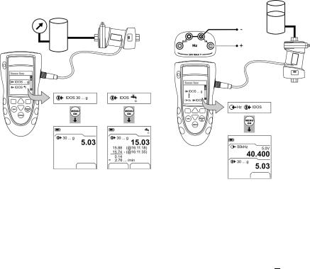
Operation - UPM Pressure measurements
Read all the instructions supplied with the UPM and then use the specified procedures to connect it (Figure 7/8).
|
|
|
|
|
|
|
Settings |
Start |
Settings |
||
a) Pressure |
|
b) Leak test |
|||
Figure 7: Example configuration - Pressure measurement with a UPM
When the connections are complete, make the necessary IDOS selections (Table 2/3).
If you re-attach a UPM, the instrument uses the same measurement units that you used before. The instrument keeps a record for the last 10 modules.
UPM - Measure the pressure
To measure the pressure (Figure 7):
1.Select the applicable pressure task from Select Task (Table 2/3) and, if necessary, adjust the Set Up (Table 1), and the Settings (Table 4/5).
2.If necessary, do a zero correction (Table 4).
To measure pressure with another operation (Figure 8), use the same procedure.
Settings
Figure 8: Example configuration - To measure pressure and frequency
UPM - Leak test
To do a leak test on a pressure system (Figure 7):
1.Select an applicable leak test from Select Task
(Table 2/3) and, if necessary, adjust the Set Up (Table 1), and the Settings (Table 4).
2.Set the period for the leak test (Table 4).
3.If necessary, do a zero correction (Table 4).
4.To start the leak test, select Start (■ ■). When the test is finished, the instrument calculates the leak rate in the applicable units/minute.
Operation - Error indications
If the display shows <<<< or >>>> :
•Make sure that the range is correct.
•Make sure that all the related equipment and connections are serviceable.
K395 Issue 3 |
[EN] English - 9 |

Maintenance
This section gives procedures to maintain the unit in a good condition. Return the instrument to the manufacturer or an approved service agent for all repairs. Do not dispose of this product as household waste. Use an approved organisation that collects and/or recycles waste electrical and electronic equipment.
For more information, contact one of these:
•our customer service department: (Contact us at www.gesensing.com)
•your local government office.
Maintenance - Clean the unit
Clean the case with a moist, lint-free cloth and a weak detergent. Do not use solvents or abrasive materials.
Maintenance - Replace the batteries B1
To replace the batteries, refer to B1. Then re-attach the cover.
Make sure that the time and date are correct. The calibration facility uses the date to give service and calibration messages.
All the other configuration options stay in memory.
Calibration
Note: GE can provide a calibration service that is traceable to international standards.
We recommend that you return the instrument to the manufacturer or an approved service agent for calibration.
If you use an alternative calibration facility, make sure that it uses these standards.
Calibration - Before you start
To do an accurate calibration, you must have:
•the calibration equipment specified in Table 8.
•a stable temperature environment: 70 ± 2°F (21 ± 1°C)
Table 8: Calibration equipment
|
|
Function |
Calibration equipment |
|
(ppm = parts per million) |
Hz |
1) Frequency meter |
|
Total error: 7 ppm or better |
|
Resolution: 8 digits (minimum) |
|
2) Signal generator |
|
|
Pressure |
UPM only. Refer to the user manual for the IDOS |
|
UPM. |
mA |
mA calibrator. |
|
Accuracy: Refer to Table 12. |
Amplitude (V) |
1) Frequency meter |
|
Total error: 7 ppm or better |
|
Resolution: 8 digits (minimum) |
|
2) Digital volt meter (DVM) |
Before you start the calibration, make sure that the time and date on the instrument are correct (Table 1).
Selection sequence:
Select Task (Table 2) Set Up (Table 1) Calibration .
1 |
Display: Enter |
2 |
3 |
Menu: |
4 |
|
5 |
|
||
Calibration PIN |
Select Channel |
|
|
|||||||
|
|
|
|
|
|
|
||||
|
|
|
|
|
|
|
|
|
|
|
|
|
|
▲ |
|
|
|
|
|
|
|
|
|
|
▼ |
|
|
|
▲ |
|
|
|
|
|
|
+ |
|
|
|
▼ |
|
|
|
|
Factory PIN = 4321 |
■ ■ |
|
(Table 9) |
|
|
|
|
|
|
|
|
|
|
|
|
|
|
|||
|
|
|
|
|
|
|
|
|||
|
|
Table 9: Calibration options |
|
|
|
|
||||
|
|
|
|
|
|
|
|
|
|
|
Options |
Description |
|
|
|
|
|
|
|
||
|
Hz |
To calibrate the input or output frequency. |
|
|
||||||
|
|
|
|
|
|
|
|
|||
|
... |
Amplitude. To select and calibrate the output |
|
|
||||||
|
|
amplitude for the Square Wave and then the |
|
|
||||||
|
|
Sine/Triangular Wave. |
|
|
|
|
||||
|
|
|
|
|
|
|
||||
|
IDOS ... |
UMM only. To calibrate the specified IDOS UMM. |
||||||||
|
|
Refer to the user manual for the IDOS UMM. |
|
|
||||||
|
|
|
|
|
|
|
|
|
||
|
mA |
DPI 842 only. To calibrate the mA input. |
|
|
|
|
||||
|
|
|
|
|
|
|
|
|||
|
|
Calibration Due: To set the date of the next |
|
|
||||||
|
|
calibration for the instrument. |
|
|
|
|
||||
|
|
After the specified calibration date, there is a |
|
|
||||||
|
|
warning message. There is a selection box to stop |
||||||||
|
|
the warning. |
|
|
|
|
|
|
|
|
|
|
|
|
|
|
|
|
|
||
|
|
To change the calibration PIN (Personal |
|
|
|
|
||||
|
|
Identification Number). |
|
|
|
|
||||
When you select a channel, the display shows the applicable instructions to complete the calibration. When the calibration is complete, select Calibration Due and set the new calibration date for the instrument.
Calibration - Procedures (Hz - input/output)
1.Connect the instrument to the calibration equipment (Figure 1).
2.Let the equipment get to a stable temperature (minimum: 5 minutes since the last power on).
3.Set up the equipment with these conditions:
Frequency meter: Gate time = one second Signal generator: Output = 10V, unipolar,
square wave Frequency = 990 Hz
DPI 841/842: Input units = Hz (Table 4)
Input trigger level = 5V (Table 4)
4.Use the calibration menu (Table 9) to do the calibration. The display shows the applicable instructions to complete the calibration.
10 - [EN] English |
K395 Issue 3 |
5.To make sure that the calibration is correct, set up the equipment to do one of these calibration checks:
•Hz input calibration check (Figure 1):
Frequency meter: Gate time = one second Signal generator: Output = 10V, unipolar,
square wave
DPI 841/842: Input trigger level = 5V (Table 4) Units (Table 4): Hz or kHz as specified in Table 10/11.
•Hz output calibration check (Figure 2):
Frequency meter: Gate time = one second DPI 841/842: Units (Table 5): Hz or kHz as
specified in Table 10/11.
6.Measure or supply the specified values (Table 10/11): Hz then kHz. Make sure that the error is in the specified limits.
Table 10: Hz error limits (Measure/Supply)
|
|
|
|
Measure/ |
Calibrator |
Permitted |
|
Supply |
error (Hz) |
DPI 841/842 error (Hz) |
|
|
|
|
|
Hz |
|
|
|
25 |
0.000175 |
0.002 |
0.0014 |
100 |
0.0007 |
0.002 |
0.0021 |
250 |
0.00175 |
0.004 |
0.0035 |
500 |
0.0035 |
0.006 |
0.0058 |
990 |
0.00693 |
0.011 |
0.0104 |
Table 11: kHz error limits (Measure/Supply)
|
|
|
|
Measure/ |
Calibrator |
Permitted |
|
Supply |
error (kHz) |
DPI 841/842 error (kHz) |
|
|
|
|
|
kHz |
|
|
|
2.5000 |
0.0175 |
0.0002 |
0.000042 |
10.0000 |
0.07 |
0.0002 |
0.000112 |
20.0000 |
0.14 |
0.0003 |
0.000205 |
30.0000 |
0.21 |
0.0004 |
0.000298 |
50.0000 |
0.35 |
0.0006 |
0.000483 |
Calibration - Procedures (mA input)
1.DPI 842 only. Connect the instrument to the calibration equipment (Figure 5).
2.Let the equipment get to a stable temperature (minimum: 5 minutes since the last power on).
3.Use the calibration menu (Table 9) to do a three-point calibration (-FS, Zero and +FS). The display shows the applicable instructions to complete the calibration.
4.To make sure that the calibration is correct, select the applicable mA input task (Table 2) and apply these values:
•mA: -55, -40, -24, -18, -12, -6, 0 (open circuit) Then mA: 0, 6, 12, 18, 24, 40, 55.
5.Make sure that the error is in the specified limits (Table 12).
Table 12: mA input error limits
|
|
|
Applied |
Calibrator |
Permitted |
mA |
error |
DPI 841/842 error |
|
(mA) |
(mA) |
±55 |
0.0022 |
0.005 |
±40 |
0.0018 |
0.004 |
|
|
|
±24 |
0.0014 |
0.003 |
|
|
|
±18 |
0.0004 |
0.003 |
|
|
|
±12 |
0.0003 |
0.002 |
|
|
|
±6 |
0.0002 |
0.002 |
|
|
|
0 (open circuit) |
- |
0.001 |
Calibration - Procedures (Amplitude output)
1.Connect the instrument to the calibration equipment (Figure 2).
2.Let the equipment get to a stable temperature (minimum: 5 minutes since the last power on).
3.Set up the DPI 841/842 with these conditions:
Output Hz = 0 (For direct current output) Output amplitude: Set to Unipolar (Table 5) Output waveform = Square Wave (Table 5)
4.Use the calibration menu (Table 9) to do the Square Wave calibration. The display shows the applicable instructions to complete the calibration.
Calibration values: Low = 0.1V, High = 20V
5.Change the output waveform to Sine Wave (Table 5).
6.Use the calibration menu (Table 9) to do the Sine/Triangular Wave calibration. The display shows the applicable instructions to complete the calibration. Calibration values: Low = 0.1V, High = 20V
K395 Issue 3 |
[EN] English - 11 |

7.To make sure that the calibration is correct, set up the DPI 841/842 with these conditions:
Output Hz = 0 (For direct current output) Output amplitude: Set to Unipolar (Table 5)
8.Supply the specified values (Table 13): Square Wave then Sine Wave. Make sure that the error is in the specified limits.
Table 13: Amplitude output error limits
|
|
Amplitude |
Permitted |
Volts (V) |
DPI 841/842 error |
|
(V) |
0.1 |
0.05 |
1.0 |
0.10 |
10.0 |
0.10 |
15.0 |
0.15 |
24.0 |
0.24 |
Calibration - Procedures (IDOS UMM)
Refer to the user manual for the IDOS UMM. When the calibration is complete, the instrument
automatically sets a new calibration date in the UMM.
Specification data
All accuracy statements are for one year.
Specification - General
|
|
|
Languages |
English [Default] |
|
Operating |
14 … 122°F (-10 … 50°C) |
|
temperature |
|
|
|
|
|
Storage |
-4 … 158°F (-20 … 70°C) |
|
temperature |
|
|
Humidity |
0 to 90% without condensation |
|
|
(Def Stan 66-31, 8.6 cat III) |
|
Shock/Vibration |
BS EN 61010:2001; Def Stan 66-31, 8.4 cat III |
|
EMC |
BS EN 61326-1:1998 + A2:2001 |
|
Safety |
Electrical - BS EN 61010:2001; CE Marked |
|
Size (L: W: H) |
7.1 x 3.3 x 2.0 in |
|
|
(180 x 85 x 50 mm) |
|
Weight |
14 oz (400 g) |
|
Power supply |
3 x AA alkaline batteries |
|
Duration |
Hz, pulses: ≈ 60 hours |
|
(Measure) |
mA: |
≈ 35 hours |
|
mA: |
≈ 10 hours (24 V Source at 12 mA) |
|
|
|
Duration |
Hz, pulses: ≈ 20 hours |
|
(Supply) |
|
|
Specification - Frequency
cpm = Pulses/minute, cph = Pulses/hour
|
|
|
|
Range (Measure): |
Accuracy: |
|
0 ... 999.999 Hz |
For all the ranges: |
|
1 ... 50.0000 kHz |
0.003% of reading + 2 counts |
|
cpm: 0 ... 99999 |
|
|
cph: 0 ... 99999 |
|
|
|
|
|
Range (Supply): |
Accuracy: |
|
0 ... 999.99 Hz |
0.003% of reading + 0.0023 Hz |
|
1 ... 50.000 kHz |
0.003% of reading + 0.0336 Hz |
|
cpm: 0 ... 99999 |
0.003% of reading + 0.138 cpm |
|
cph: 0 ... 99999 |
0.003% of reading + 0.5 cph |
|
|
|
|
Temperature coefficient |
|
|
14 … 50°F, 86 … 122°F |
0.0011% FS / °F |
|
(-10 … 10°C, 30 … 50°C) |
(0.002% FS / °C) |
|
|
|
|
Waveform |
Unipolar |
|
(Sine, square, triangle) |
Bipolar |
|
|
|
|
Voltage input |
0 ... 30 V |
|
Trigger level |
0 ... 24 V, Resolution: 0.1 V |
|
Output amplitude |
0 ... 24 V dc ± 1% |
|
|
0 ... 24 V ac ± 5% (Current ≤ 20 mA) |
|
|
|
|
Connectors (A1 - Item 10) |
Four 0.16 in (4 mm) sockets |
|
|
|
Specification - Electrical connectors (A2) |
||
|
|
|
|
Range (Measure) |
0 to ±55 mA |
|
Accuracy |
0.02% of reading + 3 counts |
|
Temperature coefficient |
|
|
14 … 50°F, 86 … 122°F |
0.0011% FS / °F |
|
(-10 … 10°C, 30 … 50°C) |
(0.002% FS / °C) |
|
|
|
|
Switch detection |
Open and closed. 2 mA current. |
|
Loop power output |
24 V ± 10% |
|
HART® resistor |
250 Ω (menu selection) |
|
Connectors (A2) |
Three 0.16 in (4 mm) sockets |
|
|
|
12 - [EN] English |
K395 Issue 3 |
DE
Druck DPI 841/842
Testtool und Kalibrator für Frequenz und Pulse
Handbuch - K395

Inhalt |
|
|
Einleitung .............................................................................. |
|
1 |
Sicherheit .............................................................................. |
|
1 |
Markierungen und Symbole auf dem Gerät ...................... |
|
2 |
Inbetriebnahme ................................................................... |
|
2 |
Tasten und Anschlüsse ................................................................ |
|
2 |
Display ................................................................................................. |
|
2 |
Vorbereiten des Geräts ................................................................ |
|
2 |
Ein-/Ausschalten ............................................................................. |
|
3 |
Grundlegende Konfiguration .................................................... |
|
3 |
Auswählen des Modus (Messen und/oder Geben) |
.......... 3 |
|
Konfigurieren der Einstellungen .............................................. |
|
4 |
Änderungsfunktionen ................................................................... |
|
4 |
Betrieb ................................................................................... |
|
6 |
Frequenzanschlüsse ..................................................................... |
|
6 |
Der Kommunikations-Port .......................................................... |
|
6 |
Messen von Hz-Werten oder Zählen von Pulsen ............. |
6 |
|
Ändern der Ausgangswerte ....................................................... |
|
6 |
Geben von Hz oder Pulsen ......................................................... |
|
7 |
Transmitterkalibrierung ............................................................... |
|
7 |
Strommessungen ........................................................................... |
|
8 |
Schaltertest ....................................................................................... |
|
8 |
UPM-Druckmessungen ................................................................ |
|
9 |
Fehleranzeigen ................................................................................ |
|
9 |
Wartung ............................................................................. |
|
10 |
Reinigen des Geräts .................................................................... |
|
10 |
Austausch der Batterien ........................................................... |
|
10 |
Kalibrierung ....................................................................... |
|
10 |
Vor dem Start ................................................................................ |
|
10 |
Verfahren (Hz - Eingang/Ausgang) ...................................... |
|
10 |
Verfahren (mA-Eingang) ........................................................... |
|
11 |
Verfahren (Amplitudenausgang) .......................................... |
|
11 |
Verfahren (IDOS-UMM) .............................................................. |
|
12 |
Technische Daten ............................................................. |
|
12 |
Allgemein ......................................................................................... |
|
12 |
Frequenz .......................................................................................... |
|
12 |
Elektrische Anschlüsse (A2) ..................................................... |
|
12 |
Kundendienst ........................................................ |
Rückseite |
|
© 2007 General Electric Company. Alle Rechte vorbehalten. Warenzeichen
Alle Produktnamen sind Warenzeichen der jeweiligen Unternehmen.
Einleitung
Das Testtool DPI 841 und der Kalibrator DPI 842 für Frequenz und Pulse gehören zur Reihe der Handheld-Serie DPI 800 von Druck.
Die Geräte dieser Serie basieren auf der IDOS-Technologie (Intelligent Digital Output Sensor). Jedes Gerät kann einfach per Plug-and-Play mit sogenannten Universalmessmodulen (UMM) erweitert werden. Beispiel: das universelle Druckmodul (UPM).
Die Geräte der Reihe DPI 841/842 bieten folgende Funktionen:
|
|
|
|
Funktion |
DPI 841 |
|
DPI 842 |
Messen/Geben einer |
|
* |
Ja |
Frequenz oder eines |
|
|
|
Pulscount |
|
|
|
|
|
||
Schritt-/Rampenfunktionen |
Automatisch/Manuell |
||
|
|
|
|
Kommunikations-Port |
|
IDOS oder RS232 |
|
|
|
|
|
Sprachauswahl |
|
Ja |
|
|
|
||
Druckmessung/Leckagetest |
** Externes IDOS UPM |
||
|
|
||
** Datenlogger |
Bis zu 1000 Anzeigen mit |
||
|
Datums-/Zeitstempel |
||
|
|
|
|
mA-Messung |
Nein |
|
0 - 55 mA |
|
|
|
|
HART®-Widerstand |
Nein |
|
Ja |
VDC-Ausgang |
Nein |
|
24 V |
|
|
|
|
Schaltertest |
Nein |
|
Ja |
|
|
|
|
Weitere Funktionen |
Halten, |
|
|
|
Maximum/Minimum/Mittelwert, |
||
|
Filter, Tara, Skalierte Werte, |
||
|
Hintergrundbeleuchtung, Alarm |
||
* Siehe „Technische Daten“. ** Optional
Sicherheit
Vor Inbetriebnahme des Geräts lesen Sie bitte sorgfältig die Bedienungsanleitung und die Anleitung für das UMM (sofern anwendbar), und informieren Sie sich über die vor Ort geltenden Sicherheitsvorschriften.
WARNUNG
•Arbeiten Sie nur innerhalb der für das Gerät angegebenen Grenzwerte und verwenden Sie nur ein einsatzbereites Gerät, um Verletzungen oder Beschädigungen des Geräts zu verhindern. Verwenden Sie die entsprechenden Schutzvorrichtungen und befolgen Sie die geltenden Sicherheitsmaßnahmen.
•Betreiben Sie das Gerät auf keinen Fall in Umgebungen mit explosiven Gasen, Dämpfen oder Staub, um Explosionen zu vermeiden.
Fortsetzung
K395 Ausgabe 3 |
[DE] Deutsch - 1 |
Sicherheit (Fortsetzung)
•Legen Sie keine höheren Spannungen als 30 V zwischen den Klemmen bzw. zwischen den Klemmen und der Masse (Erde) an, um elektrische Schläge oder Beschädigungen des Geräts zu verhindern.
•Nur UPM: Um ein schlagartiges Entweichen von Druck zu vermeiden, stellen Sie sicher, dass vor Entfernen des Druckanschlusses das System isoliert oder entlüftet wurde.
Vergewissern Sie sich, dass Sie über die erforderlichen Fähigkeiten verfügen (ggf. durch eine Schulung in einer zugelassenen Schulungseinrichtung), bevor Sie in diesem Dokument beschriebene Operationen oder Verfahren durchführen. Halten Sie sich immer an bewährte Verfahren.
Sicherheit: Markierungen und Symbole auf dem Gerät
|
|
Erfüllt die Richtlinien der |
Warnung: siehe |
Europäischen Union |
Handbuch |
|
|
Lesen Sie das Handbuch |
Batterie |
|
|
Masse (Erde) |
EIN/AUS |
Dieses Gerät darf nicht im Haushaltsmüll entsorgt werden. Siehe „Wartung“.
Inbetriebnahme
Inbetriebnahme: Tasten und Anschlüsse |
A1 |
… |
A2 |
|
|
|||
Element |
Beschreibung |
|||
1. |
|
EIN/AUS-Taste. |
||
2. |
|
|
Softkey links. Wählt die darüber im Display |
|
■ ■ |
||||
|
angegebene Funktion (Element 25). Beispiel: Edit |
|||
|
|
|
||
3.Kehrt zum vorherigen Menü zurück. ESC Beendet eine Menüoption.
Bricht eine Eingabe ab.
4.▲ Erhöht oder verringert einen Wert. ▼ Markiert ein anderes Element.
|
|
|
5. |
HOLD |
Einfrieren der momentanen Anzeige. Drücken Sie die |
|
Taste HOLD erneut, um fortzufahren. |
|
|
|
|
6. |
MENU |
Öffnet das Menü Moduswahl. |
|
Wählt oder akzeptiert ein Element oder einen Wert. |
|
|
OK |
Markiert [ ] oder hebt die Markierung auf [ ]. |
7.Softkey rechts. Wählt die darüber im Display
■■ angegebene Funktion (Element 25). Beispiel: Einstellungen
8.Display, siehe Abbildung A3.
9.Kommunikations-Port, dient zum Anschluss eines SENSOR Universalmessmoduls (UMM) oder eines
/PC RS232-Kabels.
Klemmen zur Messung (IN) oder Geben (OUT) einer Frequenz oder einer Pulsrate. Weitere Informationen siehe „Betrieb“.
|
|
11. |
Befestigung für optionales Zubehör, siehe Datenblatt. |
12. |
Batteriefach, siehe Abbildung B1. |
13., 14., 15. Nur DPI 842. Anschlüsse zur Strommessung, für die |
|
|
24-V-Spannungsquelle und für Schaltertests. |
Inbetriebnahme: Display A3
|
|
|
Element |
Beschreibung |
|
16. |
Nur DPI 842. Modusanzeige für den Schaltertest. |
|
|
= Schalter |
= Schalter offen |
|
geschlossen |
|
|
Nur UPM. Modusanzeige für den Leckagetest. |
|
|
Siehe Moduswahl (Tabelle 2/3) |
|
|
|
|
17. |
Nur DPI 842. Die 24V-Speisespannung ist |
|
|
eingeschaltet. |
|
|
Siehe Moduswahl (Tabelle 2/3) |
|
18.Der gemessene Wert erfüllt eine Alarmbedingung.
Siehe: Einstellungen (Tabelle 4)
19.Die momentane Anzeige wird eingefroren. Drücken Sie die Taste HOLD erneut, um fortzufahren.
20. |
Zeigt den Ladezustand der Batterie an: 0 ... 100 %. |
|
|
|
|
||
21. |
|
Zeigt den Datentyp und den Messbereich an. |
||
|
|
|
= Eingang |
= Ausgang |
|
|
|
= IDOS-Eingang |
|
|
|
Siehe Moduswahl (Tabelle 2/3) |
||
|
|
|||
22. ... 24. |
Die auf den Einoder Ausgang angewandten |
|||
|
|
Einstellungen. |
|
|
22. |
|
|
||
kHz |
Die Einheiten oder eine spezifizierte Skala (x:y) - |
|||
|
(Tabelle 4/5) |
|
||
|
|
|
||
|
|
|
|
|
|
|
, |
, = |
Ausgangs-Signalform |
|
|
(Tabelle 5) |
||
|
|
|
|
|
|
5,0 V |
...V |
Der Eingangs-Triggerpegel (Tabelle 4) oder |
|
|
|
|
die Ausgangsamplitude (Tabelle 5). |
|
23. |
|
|
|
|
|
, ... , |
|
= Ausgangsbetrieb (Tabelle 5) |
|
|
|
|
||
24. |
|
|
|
|
|
|
= Filter |
= Maximum |
|
|
|
|
|
= Mittelwert (Tabelle 4) |
|
|
|
= Tara |
= Minimum |
25.Softkey-Funktion. Drücken Sie den Softkey unter einer verfügbaren Funktion, um sie zu wählen. Beispiel:
= nach links |
= nach rechts |
26.Anzeige des/der Messwerts(e).
27.Das Edit-Display zum Anlegen von Textfeldern ( ≤ 6 Zeichen): x:y Skalierung (Tabelle 4).
OK = neues Textfeld übernehmen
Shift = Tasten ändern: 123ABC oder -_+abc = Leerschritt einfügen
BS = Backspace-Taste (Zeichen löschen)
Inbetriebnahme: Vorbereiten des Geräts
Vor dem ersten Einsatz des Geräts:
•Vergewissern Sie sich, dass das Gerät nicht beschädigt ist und keine Teile fehlen.
•Ziehen Sie die Plastikfolie vom Display ab. Benutzen Sie dazu die Lasche ( ) oben rechts in der Ecke.
•Setzen Sie die Batterien ein (siehe B1). Schließen Sie die Abdeckung.
2 - [DE] Deutsch |
K395 Ausgabe 3 |
Inbetriebnahme: Ein-/Ausschalten
Drücken Sie (A1 - Element [1]), um das Gerät einoder auszuschalten. Nach dem Einschalten führt das Gerät einen Selbsttest durch und zeigt die entsprechenden Daten an.
Nach dem Ausschalten bleibt der zuletzt eingestellte Modus im Speicher erhalten. Siehe „Wartung“.
Inbetriebnahme: Grundlegende Konfiguration
Konfigurieren Sie die Grundeinstellungen des Geräts mit Hilfe des Menüs Konfig.
1 |
Menü: |
2 |
3 |
Menü: |
4 |
5 |
|||
Moduswahl |
Konfig. |
||||||||
|
|
|
|
|
|
|
|||
|
|
|
|
|
|
|
|
|
|
|
|
|
▲ |
|
|
▲ |
|
|
|
|
|
|
|
|
|
|
|||
|
|
(Tabelle 2) |
▼ |
|
(Tabelle 1) |
▼ |
|
|
|
|
|
|
|
|
|||||
|
|
|
|
|
|
|
|||
|
|
|
|
|
|
|
|||
|
|
|
|
|
[ ]/[ ] |
||||
Wenn weitere Daten für eine Menüoption zur Verfügung stehen, können Sie die konfigurierten Werte anzeigen, indem Sie Einstellg. (■ ■) wählen. Ändern Sie die Werte, falls erforderlich.
Tabelle 1: Menüoptionen: Konfig.
Optionen Beschreibung
(sofern
anwendbar)
Nur DPI 842. Mit dieser Option können Sie einen Widerstand in den mA-Schaltkreis zuschalten. Sie können dann mit diesem Gerät und einem HART® Communicator/Modem HART® Geräte konfigurieren und kalibrieren.
Konfiguration der Hintergrundbeleuchtung und des
Timers.
Weitere Daten: Wählen Sie Einstellg. (■ ■)
Konfiguration der Abschaltfunktion und des Timers.
Weitere Daten: Wählen Sie Einstellg. (■ ■)
Anzeige des Ladezustands der Batterie (%)
Einstellen des Kontrasts (%).
▲ erhöht den Kontrast, ▼ verringert ihn.
Einstellen von Uhrzeit und Datum. Die Kalibrierfunktion benötigt das Datum für Wartungsund Kalibriermeldungen.
Auswahl der Bediensprache.
Kalibriermenü.
Weitere Daten: siehe „Kalibrierung“.
Auswahl und Anzeige der anwendbaren Statusinformationen (Softwareversion, Datum der nächsten Kalibrierung, Seriennummer, IDOS-Informationen).
Inbetriebnahme: Auswählen des Modus (Messen und/oder Geben)
Nach der Konfiguration des Geräts (Tabelle 1) können Sie den gewünschten Modus über das Menü Moduswahl einstellen.
1 |
Menü: |
2 |
3 |
Display: |
||
Moduswahl |
Hz-Ausgang |
|||||
|
|
|
|
|||
|
|
|
|
|
|
|
|
|
|
▲ |
|
|
|
|
|
|
|
|
||
|
|
|
▼ |
|
|
|
|
|
(Tabelle 2/3) |
|
|
Sk1 = Edit |
|
|
|
|
|
|||
|
|
|
|
|||
|
|
|
|
Sk2 = Einstellg. |
||
|
|
|
|
|
||
In Tabelle 2/3 ist IDOS ein universelles Messmodul (UMM). Bei Anschluss eines UMM an den Kommunikations-Port (A1 - Element [9]) zeigt das Menü Moduswahl die anwendbaren IDOS-Optionen an.
Tabelle 2: Menüoptionen: Moduswahl
|
|
Optionen |
Beschreibung |
(sofern |
|
anwendbar) |
|
Hz |
Eingangsmodus: |
oder |
Hz - Messen der Frequenz |
Pulse |
Pulse - Zählen der Pulse |
|
|
Hz |
Ausgangsmodus: |
oder |
Hz - Geben einer Ausgangsfrequenz |
Pulse |
Pulse - Erzeugen einer bestimmten Anzahl von |
|
Pulsen |
|
|
mA |
Nur DPI 842. mA-Modus |
mA(24V) |
Nur DPI 842. mA-Modus, mit gleichzeitiger |
|
Speisespannung. |
|
|
|
Nur DPI 842. Schaltertest. |
|
|
IDOS |
Nur UMM. IDOS-Modus. |
|
|
|
Nur UPM. Leckagetest. |
|
|
|
Gerätekonfiguration |
|
Weitere Daten: Siehe Konfiguration (Tabelle 1). |
In Tabelle 3 sind alle verfügbaren Vorgänge mit einer und zwei Funktionen aufgeführt. Bei Anschluss eines UMM können Sie nur die Optionen verwenden, die IDOS einschließen.
Tabelle 3: Zulässige Vorgänge mit einer und zwei Funktionen
|
|
|
|
|
|
|
|
|
Funktion |
|
|
|
|
|
|
||
|
|
|
|
Hz |
Hz |
Pulse |
Pulse |
IDOS |
|
|
|
|
(1) |
(1) |
(1) |
(1) |
(1) |
mA |
(1) |
x |
(2) |
x |
x |
(2) |
||
mA(24V) |
(1) |
x |
(2) |
x |
x |
(2) |
||
|
|
|
x |
x |
(2) |
x |
x |
(2) |
|
|
|
x |
x |
x |
x |
x |
(2) |
|
|
|
|
|
|
|
|
|
|
|
IDOS |
(1) |
(2) |
(2) |
(2) |
x |
x |
|
|
|
|
|
|
|
|
|
 = nur DPI 842
K395 Ausgabe 3 |
[DE] Deutsch - 3 |
Inbetriebnahme: Konfigurieren der Einstellungen
Nach der Konfiguration des Modus (Tabelle 2/3) können Sie weitere Optionen für den Ein-/Ausgangsbetrieb im Menü Einstellg. anwählen.
Display: Modus |
|
|
Auswahl der |
|
|
|
||||||||||
1 |
Einstellungen |
2 |
3 |
|||||||||||||
|
Hz + mA |
|||||||||||||||
|
|
|
(sofern anwendbar) |
|
|
|
||||||||||
|
|
|
|
|
|
|
|
|
||||||||
|
|
|
|
|
|
|
|
|
|
|
|
|
|
|
|
|
|
|
|
|
|
|
|
|
|
|
|
|
|
▲ |
|
|
|
|
|
|
|
|
|
|
|
|
|
|
|
|
|
|
||
|
|
|
■ ■ |
|
|
|
|
|
|
|
|
|
||||
|
|
|
|
|
|
|
|
|
|
▼ |
|
|
||||
|
|
|
|
|
|
|
|
|
|
|
|
|
|
|
||
Sk1 = Start/Stop |
|
|
|
|
|
|
|
|
|
|
|
|
|
|||
|
|
|
|
|
|
|
|
|
|
|
|
|
||||
|
|
|
|
|
|
|
|
|
|
|
|
|
||||
Sk2 = Einstellg. |
|
|
|
|
|
|
|
|
|
|
|
|
||||
|
|
Menü: |
|
|
4A |
|
5A |
|
6A |
Einstellg. |
||||||
|
|
Einstellg. |
|
|
|
|
|
x:y |
||||||||
|
|
|
|
|
|
|
|
|
|
|
|
|||||
|
|
|
|
|
|
|
|
|
|
|
|
|
|
|
|
|
|
|
|
|
|
|
▲ |
|
|
|
|
|
|
|
|
|
|
|
|
|
|
|
|
|
|
|
|
|
|
|
|
|
||
|
|
|
|
|
|
|
|
|
■ ■ |
|
|
|
|
|||
|
|
(Tabelle 4) |
▼ |
|
|
|
|
Sk1 = Edit |
||||||||
|
|
|
|
|
|
|
|
|||||||||
|
|
|
|
|
|
|
|
|
||||||||
|
|
|
[ ]/[ |
] |
|
|
||||||||||
|
|
Menü: |
|
|
4B |
|
5B |
|
|
|
|
|
|
|
||
|
|
Einstellg. |
|
|
|
|
|
|
|
|
|
|
||||
|
|
|
|
|
|
|
|
|
|
|
|
|
|
|||
|
|
|
|
|
|
|
|
|
|
|
|
|
|
|
|
|
|
|
|
|
|
|
▲ |
|
|
|
|
|
|
|
|
|
|
|
|
|
|
|
|
|
|
|
|
|
|
|
|
|
||
|
|
(Tabelle 5) |
▼ |
|
|
|
|
|
|
|
|
|
||||
|
|
|
|
|
|
|
|
|
|
|
||||||
|
|
|
|
|
|
|
|
|
|
|
|
|||||
|
|
|
[●]/[ |
] |
|
|
|
|
|
|||||||
Wenn weitere Daten für eine Menüoption zur Verfügung stehen, können Sie die konfigurierten Werte anzeigen, indem Sie Einstellg. (■ ■) wählen. Ändern Sie die Werte, falls erforderlich. Siehe „Änderungsfunktionen“.
Tabelle 4: (Teil der Tabelle) Menüoptionen: Einstellg. (Eingang)
|
|
|
Optionen |
Beschreibung |
|
(sofern |
|
|
anwendbar) |
|
|
... Einheiten |
Frequenz Einh. (nur Hz-Eingang). Auswahl einer |
|
|
dieser Einheiten: |
|
|
Hz: Bereich < 1000 Hz |
kHz: Bereich 1 ... 50 kHz |
|
Pulse/Minute (CPM) |
Pulse/Stunde (CPH) |
... Einheiten |
|
|
nur UPM = „Druck-Einheit“, wenn Sie einen |
||
|
IDOS-Modus wählen (Tabelle 2/3). Auswahl der |
|
|
Maßeinheit (psi, mbar ... ). |
|
|
|
|
Triggerlevel |
Einstellen der Amplitude, bei der das Gerät ein |
|
(Triggerpegel) |
Frequenzsignal misst. Standard = 5V. |
|
|
Autom. Erkennung [ ]/[ ]: Wenn diese Option |
|
|
eingestellt ist, berechnet das Gerät den Wert auf |
|
|
Basis des empfangenen Signals. |
|
|
|
|
|
Anzeige der Maximum-, Minimumund Mittelwerte |
|
|
seit Aktivierung des Modus. |
|
|
|
|
Tabelle 4: (Teil der Tabelle) Menüoptionen: Einstellg. (Eingang)
Optionen Beschreibung
(sofern
anwendbar)
Auswahl eines Tara-Werts für die Messung (ein festgelegter Wert oder der angezeigte Messwert). Das Gerät subtrahiert einen positiven Tara-Wert und addiert einen negativen.
Weitere Daten: Wählen Sie Einstellg. (■ ■).
Auswahl und Konfiguration einer Werteskala: Eine lokale Skala für jeden Modus (Maximum: 5)
Weitere Daten (Beispiel 1/2): Wählen Sie Einstellg.
(■ ■).
Auswahl der Filterfunktion. Folgende Parameter können konfiguriert werden:
Band als Prozentsatz des Endwerts (v.EW). Der Filter vergleicht jeden neuen Wert mit
dem vorhergehenden. Wenn der neue Wert außerhalb des Bandes liegt, wird er nicht gefiltert.
Tiefpassfilter-Zeitkonstante in Sekunden. Erhöhen Sie den Wert, um den
Dämpfungsfaktor zu erhöhen.
Weitere Daten: Wählen Sie Einstellg. (■ ■).
Auswahl der Alarmfunktion; Eingabe von Alarmwerten (Maximum und Minimum)
Weitere Daten: Wählen Sie Einstellg. (■ ■).
Nur UPM : Sensoren für Überdruck oder Differenzdruck. Die Druckanzeige wird zu Null gesetzt. Vor dem Ausführen bitte Sensor entlüften.
Nur für Leckagetest. Hiermit stellen Sie die entsprechende Zeitspanne für den Leckagetest in Stunden, Minuten, Sekunden ein.
Inbetriebnahme: Änderungsfunktionen
Beispiel 1) Anlegen eines Felds für x:y Skalierung = %.
Einstellg. |
1 |
|
Edit |
2 |
|
|
|
Edit |
3 |
||||||
x:y |
|
|
|
|
|||||||||||
|
|
|
|
|
|
|
|
|
|
|
|
|
|
|
|
|
|
|
|
|
|
|
|
|
|
|
|
|
|
|
|
|
|
|
|
|
|
|
▲ |
|
|
|
|
|
|
||
|
|
|
|
|
|
|
|
|
|
|
|
|
|||
|
|
|
|
|
|
|
|
|
|
|
|
Shift |
|
|
|
|
■ ■ |
|
|
|
|
▼ |
|
|
|
||||||
Sk1 = Edit |
|
|
A3 - Element |
■ ■ |
|
|
|
|
|
|
|||||
|
|
|
|
|
|
|
|
|
|
|
|||||
|
|
|
|
|
|
|
|
|
|
|
|||||
|
|
|
|
|
|
|
|
|
|
|
|||||
|
|
|
[27] |
|
|
|
|
|
|
|
|
|
|
|
|
|
|
|
|
|
|
|
|
|
|
|
|
|
|
|
|
|
|
|
Edit |
... |
|
|
Edit |
4 |
|
5 |
|||||
|
|
|
|
|
|
|
|
|
|
|
|
|
|
|
|
|
|
|
|
|
|
%_ |
|
|
|
|
|
|
▲ |
|
|
|
|
|
|
|
|
|
|
|
|
|
|
|
|||
|
|
|
|
|
|
|
|
OK |
|
▼ |
|
||||
|
A3 - Element |
|
|
|
|
|
|
|
|
■ ■ |
|
||||
|
|
|
|
|
|
|
|
|
|
|
|
||||
|
|
|
|
|
|
|
|
|
|
|
|
||||
|
|
|
|
|
|
|
|
|
|
|
|||||
|
[27] |
|
|
|
|
|
|
|
|
|
|
|
|
||
4 - [DE] Deutsch |
K395 Ausgabe 3 |
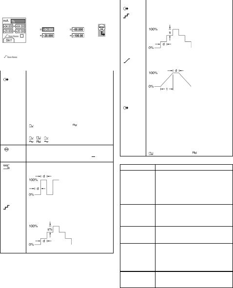
Beispiel 2) Konfiguration von Werten für x:y Skalierung = 0 bis 100 %
Einstellg. |
1 |
Einstellg. |
2 |
Edit |
3 4 |
|||
x:y |
x:y |
|||||||
|
|
|
|
|
|
|||
|
|
|
|
|
|
|
|
|
|
▲ |
|
|
|
|
▲ |
|
|
|
|
|
|
|
|
|||
|
|
|
|
|
|
|
||
|
|
■ ■ |
|
▼ |
|
|||
|
▼ |
|
|
|
||||
|
|
|
|
|
■ ■ |
|
||
|
|
|
|
|
|
|
||
Sk1 = Edit |
|
|
|
|
|
|
|
|
|
|
|
|
|
|
|
||
= Radiziert (mA, nur Druck)
Tabelle 5: (Teil der Tabelle) Menüoptionen: Einstellg. (Ausgang)
|
|
|
|
Optionen |
Beschreibung |
|
|
Hz |
|
|
|
|
|
||
... Einheiten |
Frequenz Einh.. Auswahl einer dieser Einheiten: |
||
|
Hz: Bereich < 1000 Hz |
kHz: Bereich 1 ... 50 kHz |
|
|
Pulse/min (CPM) |
|
Pulse/Stunde (CPH) |
|
|
||
Amplitude |
Einstellen der Amplitude und des Modus für das |
||
|
Ausgangssignal. Amplitude = 5 V (Standard). |
||
|
Bipolar Modus [ ]/[ ]: Wenn diese Option eingestellt |
||
|
ist, passiert das Signal den Nullpunkt. |
||
|
= Unipolar |
|
= Bipolar |
|
|
||
Signalform |
Einstellen der Signalform für das Ausgangssignal: |
||
|
, , |
= Sinus, Rechteck oder Dreieck |
|
Auswahl und Konfiguration des Ausgangs „Schritt“. Beispiel: 0,010-kHz-Schritte.
Weitere Daten: Wählen Sie Einstellg. (■ ■).
Auswahl und Konfiguration des Ausgangs „Spannentest“. Beispielhafter Ausgangszyklus:
|
Dieser Zyklus wiederholt |
|||
|
sich automatisch. |
|||
|
Weitere Daten (Tabelle 6): Wählen Sie Einstellg. (■ |
|
). |
|
|
■ |
|||
|
|
|||
% |
Auswahl und Konfiguration des |
|||
Schritt |
Ausgangs „% Schritt“. |
|||
Beispielhafter Ausgangszyklus: |
||||
|
||||
|
Auto-Wiederholg. - |
|||
|
Optional |
|||
|
Weitere Daten (Tabelle 6): Wählen Sie Einstellg. (■ |
|
). |
|
|
■ |
|||
Tabelle 5: (Teil der Tabelle) Menüoptionen: Einstellg. (Ausgang)
|
|
|
|
|
Optionen |
Beschreibung |
|
|
|
Hz |
|
|
|
|
|
|
|||
... Schritt |
Auswahl und Konfiguration des Ausgangs „Defin. |
|||
|
Schritt“. Beispielhafter Ausgangszyklus: |
|||
|
|
Auto-Wiederholg. - |
||
|
|
Optional |
||
|
Weitere Daten (Tabelle 6): Wählen Sie Einstellg. (■ |
|
). |
|
|
■ |
|||
|
|
|||
|
Auswahl und Konfiguration des Ausgangs „Rampe“. |
|||
|
Beispielhafter Ausgangszyklus: |
|||
|
|
Auto-Wiederholg. - |
||
|
|
Optional |
||
|
Weitere Daten (Tabelle 6): Wählen Sie Einstellg. (■ |
|
). |
|
|
■ |
|||
|
|
|
|
|
Optionen |
Beschreibung |
|
|
|
Pulse |
|
|
|
|
|
|
|||
|
Counts: Einstellung der Gesamtzahl an |
|||
|
Ausgangspulsen. |
|
|
|
|
Rate: Einstellen der Frequenz des Ausgangs. |
|||
|
Amplitude: Einstellen der Frequenz des |
|||
|
Ausgangssignals. Amplitude = 5 V (Standard). |
|||
|
Bipolar Modus [ ]/[ ]: Wenn diese Option eingestellt |
|||
|
ist, passiert das Signal den Nullpunkt. |
|||
|
= Unipolar |
= Bipolar |
||
Tabelle 6: Weitere Daten für Einstellg. (Ausgang):
Wert
Einstellen des 0%-Werts. Einstellen des 100%-Werts.
Einstellen der Dauer (Stunden:Minuten:Sekunden) zwischen jeder Werteänderung.
Min. (0%), Max. (100%), Halten (d): Siehe oben.
Einstellen der Werteänderung für jeden Schritt als Prozentsatz des Endwertbereichs (Max. - Min.).
Min. (0%), Max. (100%), Halten (d): Siehe oben.
Einstellen der Werteänderung für jeden Schritt als Frequenzwert.
Min. (0%), Max. (100%), Halten (d): Siehe oben.
Einstellen der Dauer (Stunden:Minuten:Sekunden) für den Wechsel vom Wert für Min. (0%) auf den Wert für Max. (100%).
Auto-Wiederholg. Wählen Sie, sofern anwendbar, dieses Element, um einen Zyklus kontinuierlich zu wiederholen.
K395 Ausgabe 3 |
[DE] Deutsch - 5 |
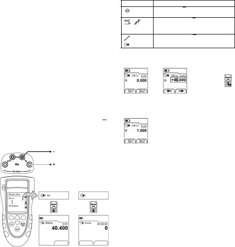
Betrieb
In diesem Abschnitt werden typische Applikationen für den Einsatz des Geräts vorgestellt. Bevor Sie beginnen:
•Lesen Sie den Abschnitt „Sicherheit“.
•Verwenden Sie nur ein Gerät ohne Beschädigungen.
Betrieb: Frequenzanschlüsse
Überprüfen Sie die Frequenzanschlüsse (A1-Element [10]) auf Korrektheit, um Fehlfunktionen des Geräts zu vermeiden.
Betrieb: Der Kommunikations-Port
Verwenden Sie den Kommunikations-Port (A1 - Element [9]) zum Anschluss eines universellen Messmoduls (UMM) in IDOS-Technologie.
Bei Anschluss eines Kabels von einem UMM (Abbildung 7/8) stellt das Gerät automatisch die
entsprechenden Menüoptionen in den geänderten Menüs zur Verfügung (Tabelle 2/3).
Betrieb: Messen von Hz-Werten oder Zählen von Pulsen
Verfahren:
1.Schließen Sie das Gerät an (Abbildung 1) und ändern Sie ggf. die Option Konfig. (Tabelle 1).
2.Wählen Sie einen Eingangsmodus Hz oder Pulse unter Moduswahl (Tabelle 2/3) und ändern Sie ggf. die Werte unter Einstellg. (Tabelle 4).
3.Verwenden Sie für Pulse die Optionen Start/Stop (■ ■), um die Zählung zu starten und stoppen. Auf dem Display wird die seit dem Start der Zählung verstrichene Zeit (Stunden:Minuten:Sekunden) angezeigt.
Pulse
Einstellg. |
Start |
Einstellg. |
a) Hz |
b) Pulse |
|
Abbildung 1: Beispielkonfiguration: Messen von Hz-Werten oder zählen von Pulsen
Betrieb: Ändern der Ausgangswerte
Wählen Sie nach der Konfiguration des Ausgangsbetriebs (Tabelle 5) eines der folgenden Verfahren, um die Ausgangswerte zu ändern:
Tabelle 7: Verfahren zum Ändern des Ausgangs
Ausgang Verfahren
Wählen Sie Edit (■ ■) und/oder verwenden Sie die Tasten ▲ ▼. Siehe Beispiel unten.
,Wählen Sie Start/Stop (■ ■) oder verwenden Sie die Tasten ▲ ▼, um die Schrittänderungen manuell vorzunehmen.
,Wählen Sie Start/Stop (■ ■).
Pulse
Beispielverfahren (Ausgang „Schritt”):
Display: |
1 |
|
Edit |
2 |
|
3 |
Edit |
4 |
|||||
Hz-Ausgang |
|
|
|||||||||||
|
|
|
|
|
|
|
|
|
|
|
|
|
|
|
|
|
|
|
|
|
|
|
|
|
|
|
|
|
|
|
|
|
|
|
|
|
|
▲ |
+01.000 |
|
|
|
|
|
|
|
|
|
|
|
|
|
|||
|
■ ■ |
|
|
|
|
■ ■ |
|
||||||
|
|
|
|
|
▼ |
|
|||||||
Sk1 = Edit |
|
|
|
|
|
|
|
|
|
|
|
|
|
|
|
|
|
|
|
|
|
|
|
|
|
|
|
|
|
|
|
|
|
|
|
|
|
|
|
|
|
Sk2 = Einstellg. |
|
|
|
|
|
|
|
|
|
|
|
|
|
Display: |
5 |
|
6 |
|
|
|
|
|
|
|
|
||
Hz-Ausgang |
|
|
|
|
|
|
|
|
|
||||
|
|
|
|
|
|
|
|
|
|
|
|
|
|
|
|
|
|
|
|
|
|
|
|
|
|
|
|
|
▲ |
1.010 |
|
▲ |
1.020 |
|
|
|
|
|
|
||
|
▼ |
|
▼ |
|
|
|
|
|
|
||||
|
|
|
|
|
|
|
|
|
|
|
|||
|
|
|
|
|
|
|
|
|
|
|
|||
|
|
|
Erhöhung |
= 0,010 |
|
|
|
|
|||||
|
|
|
|
|
(Tabelle 5) |
|
|
|
|
||||
6 - [DE] Deutsch |
K395 Ausgabe 3 |

Betrieb: Geben von Hz oder Pulsen
Verfahren:
1.Schließen Sie das Gerät an (Abbildung 2) und ändern Sie ggf. die Option Konfig. (Tabelle 1).
2.Wählen Sie einen Ausgangsmodus Hz oder Pulse unter Moduswahl (Tabelle 2/3) und ändern Sie ggf. die Werte unter Einstellg. (Tabelle 5).
Für Pulse zeigt das Display die zum Abschluss der Zählung mit der spezifizierten Rate verbleibende Zeit (Stunden:Minuten:Sekunden) an.
3.Legen Sie die Ausgangswerte an das System an (Tabelle 7).
Pulse
Pulse
Edit |
Einstellg. |
Start |
Einstellg. |
a) Hz |
b) Pulse |
||
Abbildung 2: Beispielkonfiguration: Geben von Hz oder Pulsen
Betrieb: Transmitterkalibrierung
Nur DPI 842. Verfahren:
1.Schließen Sie das Gerät an (Abbildung 3/4) und ändern Sie ggf. die Option Konfig. (Tabelle 1).
2.Wählen Sie die gewünschte Kalibrierung unter Moduswahl (Tabelle 2/3) und ändern Sie ggf. die Werte unter Einstellg. (Tabelle 4/5).
3.Legen Sie die Ausgangswerte an das System an (Tabelle 7).
Maximum: 30 V
Edit Einstellg.
Abbildung 3: Beispielkonfiguration: Transmitterkalibrierung
mit externer 2-Leiter-Speisespannung
Edit Einstellg.
Abbildung 4: Beispielkonfiguration: Transmitterkalibrierung
mit interner 2-Leiter-Speisespannung
K395 Ausgabe 3 |
[DE] Deutsch - 7 |
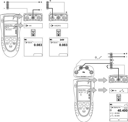
Betrieb: Strommessungen
Nur DPI 842. Strommessung:
1.Schließen Sie das Gerät an (Abbildung 5) und ändern Sie ggf. die Option Konfig. (Tabelle 1).
2.Wählen Sie den gewünschten mA-Eingangsmodus unter Moduswahl (Tabelle 2/3) und ändern Sie ggf. die Werte unter Einstellg. (Tabelle 4).
Maximum: 30 V
Einstellg. |
Einstellg. |
|
|
|
b) mit interner |
a) mit externer |
|
|
2-Leiter-Speisespannung |
2-Leiter-Speisespannung |
|
Abbildung 5: Beispielkonfiguration: Strommessung
Betrieb: Schaltertest
Nur DPI 842. Testen eines frequenzgesteuerten Schalters:
1.Schließen Sie das Gerät an (Abbildung 6) und ändern Sie ggf. die Option Konfig. (Tabelle 1).
2.Wählen Sie den gewünschten Schaltertest unter Moduswahl (Tabelle 2/3) und ändern Sie ggf. die Werte unter Einstellg. (Tabelle 5). Im Display wird der Zustand des Schalters (offen oder geschlossen) oben rechts in der Ecke angezeigt.
3.Legen Sie die Ausgangswerte an das System an (Tabelle 7).
•Beispiel: Ausgang „Schritt“
a.Stellen Sie über Edit (■ ■) einen Wert ein, der unter dem Schalterwert liegt.
b.Ändern Sie den Wert in kleinen Schritten mithilfe der Tasten ▲ ▼.
•Beispiel: Ausgang „Rampe“
a.Stellen Sie Werte für „Max.” und „Min.” ein, die auf den Schalterwert anwendbar sind (Tabelle 6). Stellen sie anschließend eine lange „Rampe“-Dauer ein, um einen präzisen Schalterwert zu erhalten.
b.Sie können den Zyklus „Rampe“ über Start/Stop (■ ■) starten und stoppen.
4.Legen Sie, falls erforderlich, die Ausgangswerte in entgegengesetzter Änderungsrichtung an, bis sich der Schalterzustand wieder ändert.
Im Display werden die zum Öffnen und Schließen des Schalters anzuwendenden Werte angezeigt.
5.Falls Sie den Test wiederholen möchten, drücken Sie die Taste ESC, um die Werte zurückzusetzen.
Edit Einstellg.
Abbildung 6: Beispielkonfiguration: Schaltertest
8 - [DE] Deutsch |
K395 Ausgabe 3 |
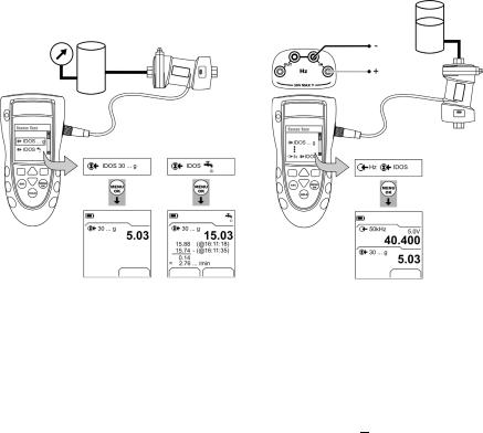
Betrieb: UPM-Druckmessungen
Lesen Sie die mit dem UPM gelieferten Anleitungen, und schließen Sie das Modul unter Beachtung der angegebenen Verfahren an (Abbildung 7/8).
Einstellg. |
Start Einstellg. |
a) Druck |
b) Leckagetest |
Abbildung 7: Beispielkonfiguration: Druckmessung mit einem UPM
Wenn die Anschlüsse hergestellt sind, treffen Sie die erforderliche IDOS-Auswahl (Tabelle 2/3).
Wenn Sie ein UPM erneut anschließen, verwendet das Gerät dieselben Maßeinheiten, die Sie zuvor verwendet haben. Das Gerät speichert Aufzeichnungen über die letzten 10 Module.
UPM - Druckmessung
Verfahren (Abbildung 7):
1.Wählen Sie den gewünschten Druckmodus unter Moduswahl (Tabelle 2/3) und ändern Sie ggf. die Werte unter Konfig. (Tabelle 1) und Einstellg. (Tabelle 4/5).
2.Führen Sie bei Bedarf einen Nullpunktabgleich durch (Tabelle 4).
Verwenden Sie zur Druckmessung mit einem anderen Betriebsmodus (Abbildung 8) dasselbe Verfahren.
Einstellg.
Abbildung 8: Beispielkonfiguration: Messung von Druck und Frequenz
UPM - Leckagetest
Ein Drucksystem auf undichte Stellen prüfen (Abbildung 7):
1.Wählen Sie den gewünschten Leckagetest unter Moduswahl (Tabelle 2/3) und ändern Sie ggf. die Werte unter Konfig. (Tabelle 1) und Einstellg. (Tabelle 4).
2.Stellen Sie die Dauer für die Messung ein (Tabelle 4).
3.Führen Sie bei Bedarf einen Nullpunktabgleich durch (Tabelle 4).
4.Wählen Sie Start (■ ■), um mit der Messung zu beginnen. Wenn die Messung beendet ist, berechnet das Gerät die Leckagerate in Einheiten/Minute.
Betrieb: Fehleranzeigen
Wenn das Display <<<< oder >>>> anzeigt:
•Überprüfen Sie, ob der korrekte Messbereich eingestellt ist.
•Stellen Sie sicher, dass alle zugehörigen Geräte und Anschlüsse funktionsfähig sind.
K395 Ausgabe 3 |
[DE] Deutsch - 9 |
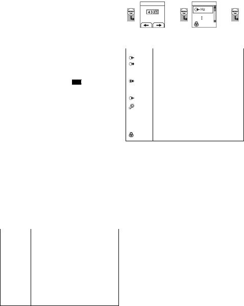
Wartung
Dieser Abschnitt beschreibt die Wartung und Pflege des Geräts. Senden Sie das Gerät für Reparaturarbeiten jeglicher Art an den Hersteller oder eine autorisierte Servicevertretung zurück.
Dieses Gerät darf nicht im Haushaltsmüll entsorgt werden. Geben Sie das Gerät bei einer autorisierten Stelle ab, die alte Elektround Elektronikgeräte sammelt und/oder wiederverwertet.
Weitere Informationen erhalten Sie bei folgenden Stellen:
•unsere Kundendienstabteilung
(Kontaktieren Sie uns unter www.gesensing.com.)
•Ihre lokale Behörde
Wartung: Reinigen des Geräts
Reinigen Sie das Gehäuse mit einem feuchten, flusenfreien Tuch und einem milden Reinigungsmittel. Verwenden Sie keine Lösungsoder Schleifmittel.
Wartung: Austausch der Batterien B1
Informationen zum Batteriewechsel finden Sie unter B1. Schließen Sie die Abdeckung.
Beachten Sie die korrekte Uhrzeit und Datum. Die Kalibrierfunktion benötigt das Datum für Wartungsund Kalibriermeldungen.
Alle anderen Konfigurationsoptionen bleiben im Speicher erhalten.
Kalibrierung
Hinweis: GE bietet Ihnen als Dienstleistung die Kalibrierung, rückführbar nach internationalen Standards, an.
Es wird empfohlen, das Gerät zur Kalibrierung an den Hersteller oder eine autorisierte Servicevertretung zu schicken.
Wenn Sie einen anderen Dienstleister beauftragen, vergewissern Sie sich, dass dieser die Standards einhält.
Kalibrierung: Vor dem Start
Für eine Kalibrierung innerhalb der Fehlergrenzen ist Folgendes erforderlich:
•die in Tabelle 8 beschriebene Kalibrierausrüstung
•eine stabile Umgebungstemperatur: 21 ± 1° C (70 ± 2° F)
Tabelle 8: Kalibrierausrüstung
|
|
Funktion |
Kalibrierausrüstung |
|
(ppm = 1 / 1 Million) |
Hz |
1) Frequenzmesser |
|
Gesamtabweichung: 7 ppm oder besser |
|
Auflösung: 8 Ziffern (Minimum) |
|
2) Signalgenerator |
|
|
Druck |
Nur UPM. Weitere Informationen zum IDOS-UPM |
|
finden Sie im Handbuch. |
mA |
mA-Kalibrator |
|
Spezifikation: Siehe Tabelle 12. |
|
|
Amplitude (V) |
1) Frequenzmesser |
|
Gesamtabweichung: 7 ppm oder besser |
|
Auflösung: 8 Ziffern (Minimum) |
|
2) Digitalvoltmesser (DVM) |
Überprüfen Sie vor Beginn der Kalibrierung, ob die Zeitund Datumseinstellung am Gerät korrekt ist (Tabelle 1).
Wählen Sie folgende Menüoptionen:
Moduswahl (Tabelle 2) Konfig. (Tabelle 1)
Kalibrierung .
1 |
Display: Eingabe |
2 |
3 |
Menü: |
4 |
|
5 |
|
|
Kalibrier-PIN |
Kanal auswählen |
|
|
||||||
|
|
|
|
|
|
|
|||
|
|
|
|
|
|
|
|
|
|
|
|
|
▲ |
|
|
|
|
|
|
|
|
|
▼ |
|
|
▲ |
|
|
|
|
|
|
+ |
|
|
▼ |
|
|
|
|
Werkseitiger PIN = |
■ ■ |
|
(Tabelle 9) |
|
|
|
|
|
|
|
|
|
|
|
|
|||
|
|
|
|
|
|
|
|||
|
4321 |
|
|
|
|
|
|
||
|
|
|
|
|
|
|
|
||
|
|
Tabelle 9: Kalibrieroptionen |
|
|
|
|
|||
|
|
|
|
|
|
|
|
|
|
Optionen |
Beschreibung |
|
|
|
|
|
|
||
|
Hz |
Kalibrierung der Einoder Ausgangsfrequenz. |
|
|
|||||
|
... |
Amplitude. Auswahl und Kalibrierung der |
|
|
|||||
|
|
Ausgangsamplitude für das Rechteck-Signal und |
|||||||
|
|
dann für das Sinus-/Dreieck-Signal. |
|
|
|
|
|||
|
|
|
|
|
|
|
|
||
|
IDOS ... |
Nur UMM. Kalibrierung des spezifizierten |
|
|
|||||
|
|
IDOS-UMM. Weitere Informationen zum IDOS-UMM |
|||||||
|
|
finden Sie im Handbuch. |
|
|
|
|
|||
|
|
|
|
|
|
|
|
||
|
mA |
Nur DPI 842. Kalibrierung des mA-Eingangs. |
|
|
|||||
|
|
Nächste Kal.: Einstellen des Datums für die nächste |
|||||||
|
|
Kalibrierung des Geräts. |
|
|
|
|
|||
|
|
Nach Ablauf des spezifizierten Kalibrierdatums |
|||||||
|
|
erscheint eine Warnmeldung. Die Warnung kann |
|||||||
|
|
über ein Auswahlfeld deaktiviert werden. |
|
|
|||||
|
|
|
|
|
|
|
|
|
|
|
|
Ändern des Kalibrier-PIN (persönliche |
|
|
|
|
|||
|
|
Identifikationsnummer). |
|
|
|
|
|||
Sobald Sie einen Kanal wählen, erscheinen im Display die entsprechenden Anweisungen, nach denen Sie die Kalibrierung abschließen.
Wählen Sie nach Abschluss der Kalibrierung Nächste Kal. und stellen Sie das neue Kalibrierdatum für das Gerät ein.
Kalibrierung: Verfahren (Frequenz - Eingang/Ausgang)
1.Schließen Sie das Gerät an die Kalibrierausrüstung an (Abbildung 1).
2.Warten Sie, bis sich die Temperatur der Ausrüstung stabilisiert hat (mindestens 5 Minuten nach dem letzten Einschalten).
3.Stellen Sie das Gerät folgendermaßen ein:
Frequenzmesser: Messzeit = eine Sekunde Signalgenerator: Ausgang = 10 V,
unipolar, Rechteck-Signal Frequenz = 990 Hz
DPI 841/842: Eingangseinheiten = Hz (Tabelle 4)
Eingangs-Triggerpegel = 5 V (Tabelle 4)
4.Führen Sie die Kalibrierung mithilfe des Kalibriermenüs (Tabelle 9) durch. Das Display zeigt die entsprechenden Anweisungen zum Abschließen der Kalibrierung an.
10 - [DE] Deutsch |
K395 Ausgabe 3 |
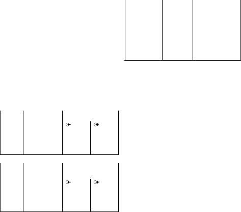
5.Konfigurieren Sie das Gerät vor der Kalibrierung für den jeweiligen Messoder Ausgangsmodus:
• Kalibrierung Frequenz-Eingang (Abbildung 1):
Frequenzmesser: Messzeit = eine Sekunde
Signalgenerator: Ausgang = 10 V, unipolar, Rechteck-Signal
DPI 841/842: Eingangs-Triggerpegel = 5 V (Tabelle 4)
Einheiten (Tabelle 4): Hz oder kHz wie in Tabelle 10/11 angegeben.
•Kalibrierung Frequenz-Ausgang (Abbildung 2):
Frequenzmesser: Messzeit = eine Sekunde
DPI 841/842: Einheiten (Tabelle 5): Hz oder kHz wie in Tabelle 10/11 angegeben.
6.Messen oder legen Sie die spezifizierten Werte an (Tabelle 10/11): Hz und danach kHz. Stellen Sie sicher, dass die Abweichung den vorgegebenen Grenzwerten entspricht.
Tabelle 10: Hz-Fehlergrenzwerte (Messen/Geben)
|
|
|
|
Messen/ |
Kalibrator- |
Zulässige |
|
Geben |
abweichung (Hz) |
DPI 841/842-Abweichung (Hz) |
|
|
|
|
|
Hz |
|
|
|
25 |
0,000175 |
0,002 |
0,0014 |
100 |
0,0007 |
0,002 |
0,0021 |
250 |
0,00175 |
0,004 |
0,0035 |
500 |
0,0035 |
0,006 |
0,0058 |
990 |
0,00693 |
0,011 |
0,0104 |
Tabelle 11:
|
|
|
|
Messen/ |
Kalibrator- |
Zulässige |
|
Geben |
abweichung (kHz) |
DPI 841/842-Abweichung |
|
|
|
(kHz) |
|
kHz |
|
|
|
2,5000 |
0,0175 |
0,0002 |
0,000042 |
10,0000 |
0,07 |
0,0002 |
0,000112 |
20,0000 |
0,14 |
0,0003 |
0,000205 |
30,0000 |
0,21 |
0,0004 |
0,000298 |
50,0000 |
0,35 |
0,0006 |
0,000483 |
Kalibrierung: Verfahren (mA-Eingang)
1.Nur DPI 842. Schließen Sie das Gerät an die Kalibrierausrüstung an (Abbildung 5).
2.Warten Sie, bis sich die Temperatur der Ausrüstung stabilisiert hat (mindestens 5 Minuten nach dem letzten Einschalten).
3.Führen Sie mithilfe des Kalibriermenüs (Tabelle 9) eine 3-Punkt-Kalibrierung (-v.EW, Null und +v.EW) durch. Das Display zeigt die entsprechenden Anweisungen zum Abschließen der Kalibrierung an.
4.Wählen Sie zur Überprüfung der Kalibrierung den zutreffenden mA-Eingangsmodus (Tabelle 2) und legen Sie folgende Werte an:
•mA: -55, -40, -24, -18, -12, -6, 0 (Leerlauf) Dann mA: 0, 6, 12, 18, 24, 40, 55.
5.Stellen Sie sicher, dass die Abweichung den vorgegebenen Grenzwerten entspricht (Tabelle 12).
Tabelle 12: mA-Eingang: Zulässige Abweichungen
|
|
|
Angelegter |
Kalibrator- |
Zulässige |
mA-Wert |
abweichung |
DPI 841/842-Abweichung |
|
(mA) |
(mA) |
±55 |
0,0022 |
0,005 |
±40 |
0,0018 |
0,004 |
|
|
|
±24 |
0,0014 |
0,003 |
|
|
|
±18 |
0,0004 |
0,003 |
|
|
|
±12 |
0,0003 |
0,002 |
|
|
|
±6 |
0,0002 |
0,002 |
|
|
|
0 (Leerlauf) |
- |
0,001 |
Kalibrierung: Verfahren (Signalamplitude am Ausgang)
1.Schließen Sie das Gerät an die Kalibrierausrüstung an (Abbildung 2).
2.Warten Sie, bis sich die Temperatur der Ausrüstung stabilisiert hat (mindestens 5 Minuten nach dem letzten Einschalten).
3.Stellen Sie den DPI 841/842 folgendermaßen ein:
Ausgangs-Hz = 0 (für Gleichspannungsausgang) Ausgangsamplitude: Auf Unipolar (Tabelle 5) einstellen Ausgangssignalform = Rechteck-Signal (Tabelle 5)
4.Führen Sie die Kalibrierung des Rechteck-Signals mithilfe des Kalibriermenüs (Tabelle 9) durch. Das Display zeigt die entsprechenden Anweisungen zum Abschließen der Kalibrierung an.
Kalibrierwerte: Tief = 0,1 V, Hoch = 20 V
5.Ändern Sie die Ausgangssignalform in Sinus-Signal (Tabelle 5).
6.Führen Sie die Kalibrierung des Sinus-/Dreieck-Signals mithilfe des Kalibriermenüs (Tabelle 9) durch. Das Display zeigt die entsprechenden Anweisungen zum Abschließen der Kalibrierung an.
Kalibrierwerte: Tief = 0,1 V, Hoch = 20 V
K395 Ausgabe 3 |
[DE] Deutsch - 11 |

7.Stellen Sie zur Überprüfung der Kalibrierung den DPI 841/842 folgendermaßen ein:
Ausgangs-Hz = 0 (für Gleichspannungsausgang) Ausgangsamplitude: Auf Unipolar (Tabelle 5) einstellen
8.Legen Sie die spezifizierten Werte an (Tabelle 13):
Rechteck-Signal, dann Sinus-Signal. Stellen Sie sicher, dass die Abweichung den vorgegebenen Grenzwerten entspricht.
Tabelle 13: Signalamplitude am Ausgang:
Zulässige Abweichungen
|
|
Amplitude |
Zulässige |
Volt (V) |
DPI 841/842-Abweichung |
|
(V) |
0,1 |
0,05 |
1,0 |
0,10 |
10,0 |
0,10 |
15,0 |
0,15 |
24,0 |
0,24 |
Kalibrierung: Verfahren (IDOS-UMM)
Weitere Informationen zum IDOS-UMM finden Sie im
Handbuch.
Nach Abschluss der Kalibrierung stellt das Gerät automatisch ein neues Kalibrierdatum im UMM ein.
Technische Daten
Alle Angaben zur Spezifikation gelten für ein Jahr.
Technische Daten: Allgemein
|
|
|
Sprachen |
Englisch [Standard] |
|
Betriebstemperatur |
-10 … 50° C (14 … 122° F) |
|
Lager- |
-20 … 70° C (-4 … 158° F) |
|
temperatur |
|
|
|
|
|
Feuchtigkeit |
0 bis 90 % nicht kondensierend |
|
|
(Def.-Stan. 66-31, 8.6 Kat. III) |
|
Stoß/Vibrationen |
BS EN 61010:2001; Def.-Stan. 66-31, 8.4 Kat. III |
|
EMV |
BS EN 61326-1:1998 + A2:2001 |
|
Sicherheit |
Elektrische: BS EN 61010:2001; |
|
|
CE-Kennzeichen |
|
Größe (L: B: H) |
180 x 85 x 50 mm |
|
|
|
|
Gewicht |
400 g |
|
Spannungsversorg |
3 x AA Alkalibatterien |
|
ung |
|
|
|
|
|
Betriebsdauer |
Hz, Pulse: ≈ 60 Stunden |
|
(Messen) |
mA: ≈ |
35 Stunden |
|
mA: ≈ |
10 Stunden (24V-Versorgung bei 12 mA) |
|
|
|
Betriebsdauer |
Hz, Pulse: ≈ 20 Stunden |
|
(Geben) |
|
|
Technische Daten: Frequenz
CPM = Pulse/Minute, CPH = Pulse/Stunde
|
|
|
|
Bereich (Messen): |
Spezifikation: |
|
0 ... 999,999 Hz |
Für alle Bereiche: |
|
1 ... 50,0000 kHz |
0,003 % v. Messwert + 2 Digit |
|
Pulse pro Minute: 0 ... 99999 |
|
|
Pulse pro Stunde: 0 ... 99999 |
|
|
|
|
|
Bereich (Geben): |
Spezifikation: |
|
0 ... 999,99 Hz |
0,003 % v. Messwert + 0,0023 Hz |
|
1 ... 50,000 kHz |
0,003 % v. Messwert + 0,0336 Hz |
|
CPM: 0 ... 99999 |
0,003 % v. Messwert + 0,138 Pulse |
|
CPH: 0 ... 99999 |
pro Minute |
|
|
0,003 % v. Messwert + 0,5 Pulse pro |
|
|
Stunde |
|
|
|
|
|
|
|
Temperaturfehler |
|
|
-10 … 10° C, 30 … 50° C |
0,002 % v. Endwert / °C |
|
(14 … 50° F, 86 … 122° F) |
(0,0011 % v. Endwert / °F) |
|
|
|
|
Signalform |
Unipolar |
|
(Sinus, Rechteck, Dreieck) |
Bipolar |
|
|
|
|
Spannungseingang |
0 ... 30 V |
|
|
|
|
Triggerpegel |
0 ... 24 V, Auflösung: 0,1 V |
|
|
|
|
Ausgangsamplitude |
0 ... 24 VDC ± 1 % |
|
|
|
|
|
0 ... 24 VAC ± 5 % (Strom ≤ 20 mA) |
|
|
|
|
Anschlüsse (A1 - Element |
vier 4mm-Buchsen |
|
10) |
|
|
|
|
Technische Daten: Elektrische Anschlüsse (A2) |
||
|
|
|
|
Bereich (Messen) |
0 bis ±55 mA |
|
Spezifikation |
0,02 % v. Messwert +3 Digit |
|
|
|
|
Temperaturfehler |
|
|
-10 … 10° C, 30 … 50° C |
0,002 % v. Endwert / °C |
|
(14 … 50° F, 86 … 122° F) |
(0,0011 % v. Endwert / °F) |
|
|
|
|
Schaltererkennung |
offen und geschlossen, 2 mA Strom |
|
Speisespannung |
24 V ± 10 % |
|
HART®-Widerstand |
250 Ω (Menüauswahl) |
|
Anschlüsse (A2) |
drei 4mm-Buchsen |
|
|
|
12 - [DE] Deutsch |
K395 Ausgabe 3 |
 Loading...