


 Loading...
GE Industrial
Sensing
Druck DPI 104
Digital pressure indicator User manual - K394

A1.1 |
|
A1.2 |
|
|
B1 |
|
|
|
|
|
|
|
|
|
|
|
|
1
A2 |
B2
2 |
6 |
A1.3 |
7 |
|
|
|
|
5 |
|
8 |
|
3 |
|
||
|
|
|
|
|
4 |
|
|
9
10
A2
13 |
12 |
11 |
14
16
15
K394 Issue 1
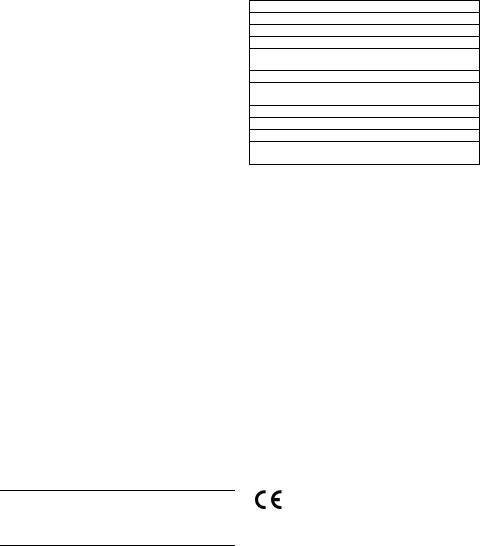
Table of Contents |
|
Introduction ......................................................................... |
1 |
Safety .................................................................................... |
1 |
Marks and symbols on the DPI 104 ....................................... |
1 |
To Start ................................................................................. |
2 |
Location of items ........................................................................... |
2 |
Items on the display .................................................................... |
2 |
Prepare the instrument ............................................................... |
2 |
Power on or off ................................................................................ |
2 |
Menu operation ............................................................................... |
3 |
Installation ........................................................................... |
4 |
Battery .................................................................................................. |
4 |
Position ................................................................................................ |
4 |
Pressure connections ................................................................... |
4 |
Electrical connections .................................................................. |
4 |
Operation ............................................................................. |
5 |
Menu: Set units ................................................................................ |
5 |
Menu: Set tare .................................................................................. |
5 |
Menu: Monitor maximum/minimum ..................................... |
5 |
Menu: Monitor a pressure switch ............................................ |
6 |
Menu: Calibration ........................................................................... |
6 |
Menu: Set low/high alarm .......................................................... |
6 |
Menu: Supply voltage output (Vout) ...................................... |
6 |
Menu: Set Vout scale factor ...................................................... |
7 |
Menu: Set automatic power OFF ............................................. |
7 |
Menu: Set lock code ....................................................................... |
7 |
Menu: Set scan rate ....................................................................... |
7 |
Menu: Monitor external IDOS .................................................... |
7 |
Menu: Set FSO low/high registers ........................................... |
8 |
Set up a DPI 104 network ........................................................... |
8 |
Error indications .............................................................................. |
8 |
Maintenance ........................................................................ |
9 |
Replace the batteries .................................................................... |
9 |
Restore the original configuration .......................................... |
9 |
Calibration ............................................................................ |
9 |
Equipment and conditions ......................................................... |
9 |
Procedures ......................................................................................... |
9 |
Specification data ............................................................. |
11 |
General ............................................................................................. |
11 |
Pressure measurement ............................................................ |
11 |
Electrical .......................................................................................... |
11 |
Customer service ............................................... |
Back cover |
© 2005 General Electric Company. All rights reserved. Trademarks
All product names are trademarks of their respective companies.
Introduction
The Druck DPI 104 is a digital pressure indicator that measures the pressure of liquid, gas or vapour and shows the pressure value on a liquid crystal display (LCD). It also has the Intelligent Digital Output Sensor (IDOS) technology to use data from a Universal Pressure Module (UPM).
The DPI 104 includes these functions:
Function
* Measure pressure - Accuracy: 0.05% full scale (FS)
Large 5-digit main display with 11 pressure units
Adjustable Full Scale Output (FSO)
20 segment analogue dial in increments of 5% FSO (large division marks = 10% increments).
2.5 digit percentage indicator (0-100% FSO)
8-pin connector port: For RS232, **IDOS UPM, external power supply
Alarm output for high/low pressure conditions
Switch input to monitor an external pressure switch
Analogue voltage output (Vout): 0 - 5 Vdc
Other functions: Maximum/minimum, tare, Vout scale factor, automatic power off
*Refer to “Specification data”.
**Optional item
Safety
Before you use the DPI 104, make sure that you read and understand all the related data. This includes: all local safety procedures, and this publication.
WARNING
•Some liquid and gas mixtures are dangerous. This includes mixtures that occur because of contamination. Make sure that the DPI 104 is safe to use with the necessary media.
•It is dangerous to ignore the specified limits for the DPI 104 or to use the DPI 104 when it is not in its normal condition. Use the applicable protection and obey all safety precautions.
•To prevent a dangerous release of pressure, isolate and bleed the system before you disconnect a pressure connection.
•Do not use the DPI 104 in locations with explosive gas, vapour or dust. There is a risk of an explosion.
Before you start an operation or procedure, make sure that you have the necessary skills (if necessary, with qualifications from an approved training establishment). Follow good engineering practice at all times.
Safety - Marks and symbols on the DPI 104
Complies with European Union directives
K394 Issue 1 |
[EN] English - 1 |
To Start
To start - Location of items A1
|
|
Item |
|
Description |
|
|
|
|
|
1. |
|
8-pin connector for external power supplies, |
|||
|
|
|
|
RS232/UPM connections and signal input/output. |
|||
|
|
|
|
|
|
|
|
|
|
2. |
• |
Power on button |
|
|
|
|
|
|
• |
Menu mode: Press for 2 seconds to show the first |
|||
|
|
|
|
menu option. To move down the menu structure, |
|||
|
|
|
|
press again and again, or press and hold. |
|||
|
|
|
• |
Reject or stop the change to a value. |
|||
|
|
|
• |
In Maximum/minimum mode. Press to show the |
|||
|
|
|
|
maximum and minimum values since the last reset. |
|||
|
|
|
|
= maximum |
|
= minimum |
|
|
|
|
|
|
|
|
|
|
|
3. |
|
In menu mode: |
|
|
|
|
|
|
|
- On/OFF selection |
|
|
|
|
|
|
|
- Increase/decrease a value |
|||
|
|
|
|
- Move the decimal left/right |
|||
|
|
|
|
|
|
|
|
|
|
4. |
|
Pressure sensor and connector with 320° of turn: |
|||
|
|
|
|
gauge (g), absolute (a) or Sealed gauge (sg). Refer to |
|||
|
|
|
|
“Specification data”. |
|
|
|
|
|
|
|
|
|
|
|
|
|
5. |
• |
In menu mode: |
|
|
|
|
|
|
|
- Accepts a menu selection |
|||
|
|
|
|
- Shows the next menu level |
|||
|
|
|
|
- Accepts a value |
|
|
|
|
|
|
• |
|
|
|
|
|
|
|
In Tare mode: Tare the pressure value on the display. |
||||
|
|
|
• |
|
|
|
|
|
|
|
In Maximum/minimum mode. Reset the |
||||
|
|
|
|
maximum/minimum values. |
|||
|
|
|
|
|
|
|
|
|
|
6. |
|
Display bezel with 348° of turn. |
|||
|
|
7. |
|
O-ring. |
|
|
|
|
|
8. |
|
Battery connector |
|
|
|
|
|
9. |
|
Battery: 9 V Alkaline (supplied but not installed). Refer |
|||
|
|
|
|
to “Installation”. |
|
|
|
|
|
|
|
|
|
|
|
|
|
10. |
|
Battery clamp with two screws. |
|||
|
|
|
|
|
|
|
|
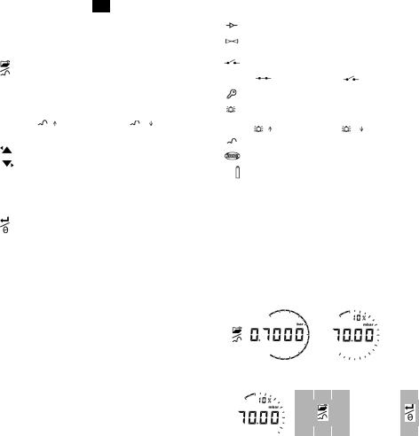
To start - Items on the display |
|
|
|||||
A2 |
|
|
|||||
|
|
|
|
|
|
|
|
|
|
Item |
|
Description |
|
|
|
|
|
11. |
|
5-digit main display. |
|
|
|
|
|
12. |
|
2.5-digit percentage indicator (0-100% FSO). |
|
||
|
|
|
|
%FSO = [Applied Pressure/(FSOHigh—FSOLow)] * 100 |
|
||
|
|
|
|
|
|
|
|
|
|
13. |
|
20 segment analogue dial in increments of 5% FSO |
|
||
|
|
|
|
(large division marks = 10% increments). |
|
||
|
|
|
|
%FSO = [Applied Pressure/(FSOHigh—FSOLow)] * 100 |
|
||
|
|
|
|
|
|
|
|
|
|
14. |
|
The units of measurement: kPa, MPa, kg/cm2, psi, |
|
||
|
|
|
|
mbar, bar, mmHg, mmH2O, mH2O, inH2O, inHg |
|
||
|
|
|
|
|
|
Continued |
|
Item |
Description |
|
15. |
Mode indication. |
|
|
Voltage output (Vout) mode - On. |
|
|
|
|
|
RS232 connection. The data transmit/receive function |
|
|
is active. |
|
|
|
|
|
Switch mode - On. To monitor an external pressure |
|
|
switch. |
|
|
= switch closed |
= switch open |
|
|
|
|
Menu Lock mode - On. To restrict access to the menu |
|
|
functions. |
|
|
Alarm mode - On. The symbol flashes when the |
|
|
measured value satisfies one of the alarm conditions. |
|
|
= High alarm |
= Low alarm |
|
|
|
|
Maximum/minimum mode - On. |
|
|
|
|
|
IDOS UPM mode - On. To monitor pressure from a UPM |
|
|
|
|
16. |
Low battery power indication: Battery life ≤ 15%. |
|
|
|
|
To start - Prepare the instrument
Before you use the instrument for the first time:
•Make sure that there is no damage to the instrument, and that there are no missing items.
•Install the battery (refer to “Installation”). Then re-attach the display bezel [A1: item 6].
To start - Power on or off
Press the buttons in the sequence shown below.
• Power on sequence:
1 |
|
First display = |
Then: |
|
|
FS limit |
Normal output |
||
|
|
|
||
|
|
|
|
|
|
|
|
|
|
|
|
|
|
|
|
|
|
|
|
• Power off sequence:
Normal output 1 Menu: 2
OFF
(For 2 seconds)
When the power is off, the last set of configuration options stays in memory.
Note: The DPI 104 uses a small quantity of power while it is OFF. If you put it into storage for a long period, disconnect the battery (refer to “Installation”).
2 - [EN] English |
K394 Issue 1 |
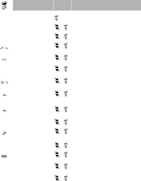
To start - Menu operation
|
|
|
Menu Description |
Steps |
|
|
|
|
|
1 |
2 |
|
|
|
|
|
|
|
|
|
|
|
|
OFF |
= |
Power supply: OFF only |
|
- |
|
|
|
|
|
|
|
|
|
|
|
|
|
unitS |
= |
Set units: (A2: item 14). |
|
|
|
|
|
|
|
|
|
|
|
|
|
|
|
t OFF |
= |
Set tare: Set to On or OFF. |
|
|
|
|
|
= |
Monitor maximum/minimum: |
|
|
|
|
|
|
||
OFF |
|
|
|||
|
Set to On or OFF |
|
|
||
|
|
|
|
|
|
|
|
= Monitor a pressure switch: |
|
|
|
|
|
|
|
||
OFF |
|
|
|||
|
Set to On or OFF. |
|
|
||
|
|
|
|
|
|
|
|
|
|
|
|
|
|
|
|
|
|
C _ _ _ _ |
= |
Calibration: To continue, set the |
|
|
|
|
|
|
correct calibration access code = |
|
|
|
|
|
|
|
|
|
|
|
Serial number: Last four digits. |
|
|
|
|
|
|
|
|
A OFF |
= |
Set low/high alarm: Set to On or OFF. |
|
|
|
|
|
|
|
|
|
|
|
|
|
|
|
OFF |
= |
Supply voltage output (Vout): |
|
|
|
|
|
|
Set to OFF, P-V, or US. |
|
|
|
|
|
|
|
|
|
|
|
|
|
|
S 1.00 |
= |
Set Vout scale factor: A Vout |
|
|
|
|
|
|
adjustment. |
|
|
|
|
|
|
|
|
|
|
|
|
|
|
Au On |
= |
Set automatic power OFF: |
|
|
|
|
|
|
Set to On or OFF. |
|
|
|
|
|
|
|
|
|
|
|
|
|
|
L OFF |
= |
Set lock code: A menu protection |
|
|
|
|
|
|
facility. Set to On or OFF. |
|
|
|
|
Set scan rate: A rate to update the |
|
|
|
|
|
|
|
|
|
Sc 02 |
= |
|
|
||
|
|
|
maximum/minimum values |
|
|
|
|
|
|
|
|
|
|
|
|
|
|
OFF |
= |
Monitor external IDOS: Set to On or |
|
|
|
|
|
|
OFF. |
|
|
|
|
|
|
|
|
|
↓ |
|
|
|
|
FS |
= |
Set FSO low register: To set a |
|
|
|
|
|
|
different range for these functions: |
|
|
|
|
|
|
|
|
|
|
|
analogue display, %, alarm. |
|
|
|
↑ |
|
|
|
|
FS |
= |
Set FSO high register: To set a |
|
|
|
|
|
|
different range for these functions: |
|
|
|
|
|
|
|
|
|
|
|
analogue display, %, alarm. |
|
|
Normal |
|
|
|
|
|
display |
|
|
|
|
|
Result/Subsequent steps
Power goes off
Pressure value changes to the applicable units:
psi, mbar, bar ...
On tA 00.000 : Set a tare value (Refer to Table 4)
Monitor function is set on or off
Monitor function is set on or off
C0 (Correct the zero offset value)
C2 (Do a two-point pressure calibration)
V2 (Do a two-point voltage calibration). Refer to “Calibration”.
On 000.0 ↓ 100.0 ↑
Set a value for the low and/or high alarm (0 to 105% FSO).
P-V: Vout is proportional to the pressure value on the display. Make sure the Vout scale factor is correct.
US 000.0: Set a Vout value (0 to 100%) to control an external pressure regulator. Make sure the Vout scale factor is correct.
If applicable, set a new Vout scale factor (0.01 to 9.99). Factory value = 1.00
On Au 15 : Set the period for automatic power OFF (1 to 99 minutes). Factory value = 15 minutes.
On L 000 : Set a new lock code (If necessary).
Factory code = 000.
Set an applicable rate (02 to 10 Hz).
Factory value = 02 Hz.
Monitor function is set on or off
Set a value for the low end of the range (Refer to Table 5). Factory value = Factory calibration value.
Set a value for the high end of the range (Refer to Table 5). Factory value = Factory calibration value.
K394 Issue 1 |
[EN] English - 3 |
Loading...