


Pressure measurement for research & industry
Druck Limited
Fir Tree Lane
Groby
Leicester LE6 0FH
England
Tel: 0116 231 7100
PACE Indicator Series
Programmable Automated
Calibration Equipment
User Manual
K0470
Druck Limited 2011
This document is the property of Druck Limited and may not, either in part or whole, be copied or otherwise reproduced, communicated in any way to third parties, nor stored in any data processing system, without the express written authority of Druck Limited.
Page 1 of 60 |
K0470 Issue 2 |

Amendment Record
|
|
Iss No |
Date |
C/N No |
Originator |
Typed |
|
Workflow |
Amendments |
|
||
|
|
|
|
|
|
|||||||
|
|
|
|
|
|
|
|
|
No. |
|
|
|
|
1 |
11/11/10 |
N/A |
Robert Lee |
Robert Lee |
|
154363 |
New document |
|
|||
|
|
|
|
|
|
|
|
|
|
|
|
|
|
2 |
08/12/10 |
25859 |
Robert Lee |
Robert Lee |
|
158514 |
Add safety environmental conditions. |
|
|||
|
|
|
|
|
|
|
|
|
|
|
|
|
|
|
|
|
|
|
|
|
Approvals |
|
|
|
|
|
|
|
|
|
|
|
|
|
|
|
||
|
|
|
|
|
|
|
|
|
|
|
||
|
Engineering |
|
|
Marketing |
|
|
|
|
|
|||
|
P BRADLEY |
|
|
M SINGLETON |
|
|
|
|||||
|
|
|
|
|
|
|
|
|
|
|
||
|
Technical Communications |
|
|
|
|
|
|
|
|
|||
|
R LEE |
|
|
|
|
|
|
|
|
|
|
|
|
|
|
|
|
|
|
|
|
|
|
|
|
Page 2 of 60 |
K0470 Issue 2 |
Print Instructions: K0470
•Finished Size: 180 x 230 mm)
•Print in black on white throughout (covers + text), wiro-bind.
•Cover to 285 gsm, content to 100 gsm.
THIS HARDCOPY IS NOT TO BE USED AS CAMERA COPY.
Page 3 of 60 |
K0470 Issue 2 |
Page 4 of 60 |
K0470 Issue 2 |

GE
Measurement & Control Solutions
PACE Indicators
Pressure Automated Calibration Equipment
User manual K0470
© The General Electric Company. All rights reserved
Introduction
This manual contains Installation and operating instructions for PACE Pressure Indicators.
Safety
The manufacturer has designed this equipment to be safe when operated using the procedures detailed in this manual. Do not use this equipment for any other purpose than that stated, the protection provided by the equipment may be impaired.
This publication contains operating and safety instructions that must be followed to make sure of safe operation and to maintain the equipment in a safe condition. The safety instructions are either warnings or cautions issued to protect the user and the equipment from injury or damage.
Use qualified * technicians and good engineering practice for all procedures in this publication.
Pressure
Do not apply pressures greater than the maximum working pressure to the equipment.
Toxic Materials
There are no known toxic materials used in construction of this equipment.
Maintenance
The equipment must be maintained using the procedures in this publication. Further manufacturer’s procedures should be done by an authorized service agents or the manufacturer’s service departments.
Technical Advice
For technical advice contact the manufacturer.
* A qualified technician must have the necessary technical knowledge, documentation, special test equipment and tools to carry out the required work on this equipment.
General Specification
Display |
LCD: Colour display with touch-screen |
EMC |
EN 61326 |
Electrical safety |
EN 61010-1, UL61010-1, CSA 22.2, No. 61010-1 and IEC61010-1 |
Power adaptor |
Input range: 100 - 240VAC, 50 to 60Hz, 700mA. Installation category II |
Pressure safety |
Pressure Equipment Directive - class: sound engineering practice (SEP) |
|
|
K0470 Issue No. 2 |
i |
Environmental conditions
For indoor use only |
|
Operating temperature |
10°C to 50°C (50° to 122°F) |
Storage temperature |
-20°C to 70°C (-4° to 158°F) |
Ingress protection |
IP20 (EN60529) |
Operating humidity |
5% to 95% RH (non-condensing) |
Vibration |
MIL-PRF-28800 Type 2 class 5 style E/F |
Operating altitude |
Maximum 2000 metres (6560ft) |
Pollution degree |
2 |
|
|
Abbreviations
The following abbreviations are used in this manual; abbreviations are the same in the singular and plural.
a |
Absolute |
min |
Minute or minimum |
|
a.c |
Alternating current |
mm |
millimetre |
|
ALT |
Altitude |
mV |
millivolts |
|
ASCII |
American Standard Code for Information Interchange |
MWP |
Maximum working pressure |
|
BSP |
British pipe thread |
No |
Number |
|
CAS |
Calibrated airspeed |
NPT |
National Pipe Thread |
|
CSK |
Countersunk |
PACE |
Pressure automated calibration |
|
equipment |
||||
|
|
|
||
d.c. |
Direct current |
Para. |
Paragraph |
|
DPI |
Digital Pressure Instrument |
PDCR |
Pressure transducer |
|
etc. |
And so on |
PED |
Pressure equipment directive |
|
e.g. |
For example |
psi |
Pounds per square inch |
|
Fig. |
Figure |
PTX |
Pressure transmitter |
|
ft |
Foot |
ROC |
Rate of climb (vertical speed) |
|
g |
Gauge |
RS232 |
Serial communications standard |
|
GPIB |
General purpose interface bus |
Rt CAS |
Rate of Calibrated airspeed |
|
Hg |
Mercury |
Rt MACH |
Rate of MACH |
|
Hz |
Hertz |
Rx |
Receive data |
|
IAS |
Indicated airspeed |
SCPI |
Standard commands for |
|
programmable instruments |
||||
|
|
|
||
IDOS |
Intelligent digital output sensor (GE product) |
SDS |
Sales data sheet |
|
i.e. |
That is |
SELV |
Separated (or Safety) extra low |
|
voltage |
||||
|
|
|
||
IEEE 488 |
Institute of Electrical and Electronic Engineers standard |
Tx |
Transmit data |
|
488 (for programmable devices with a digital interface) |
||||
in |
Inch |
UUT |
Unit under test |
|
kg |
kilogram |
V |
Volts |
|
kts |
knots |
+ve |
Positive |
|
m |
Metre |
-ve |
Negative |
|
mA |
milliampere |
°C |
Degrees Celsius |
|
max |
Maximum |
°F |
Degrees Fahrenheit |
|
mbar |
Millibar |
|
|
K0470 Issue No. 2 |
ii |
Related publications
K0467 User Guide and Safety Instructions
K0469 PACE Heritage Communications Manual
K0450 PACE Series Calibration Manual
K0472 PACE Series SCPI Manual
Symbols
The equipment contains the following symbols to identify hazards.
This equipment meets the requirements of all relevant European safety directives. The equipment carries the CE mark.
This symbol, on the instrument, indicates that the user should refer to the user manual. This symbol, in this manual, indicates a hazardous operation.
Ce symbole, sur l’instrument, indique que l’utilisateur doit consulter le manuel d’utilisation. Ce symbole, dans le manuel, indique une situation dangereuse.
This symbol, on the instrument, indicates do not throw-away in domestic bin, hazardous material, dispose correctly in accordance with local regulations.
|
|
|
|
K0470 Issue No. 2 |
iii |
||
Pressure units and conversion factors
|
|
|
|
|
|
|
Pressure units |
Factor (hPa) |
Pressure units |
Factor (hPa) |
|
|
|
|
|
|
|
|
mbar |
1.0 |
cmH2O @ 20°C |
0.978903642 |
|
|
|
|
|
|
|
|
bar |
1000.0 |
mH2O @ 20°C |
97.8903642 |
|
|
|
|
|
|
|
|
Pa (N/m2) |
0.01 |
kg/m2 |
0.0980665 |
|
|
hPa |
1.0 |
kg/cm2 |
980.665 |
|
|
kPa |
10.0 |
torr |
1.333223684 |
|
|
|
|
|
|
|
|
MPa |
10000.0 |
atm |
1013.25 |
|
|
|
|
|
|
|
|
mmHg @ 0°C |
1.333223874 |
psi |
68.94757293 |
|
|
|
|
|
|
|
|
cmHg @ 0°C |
13.33223874 |
lb/ft2 |
0.4788025898 |
|
|
mHg @ 0°C |
1333.223874 |
inH2O @ 4°C |
2.4908891 |
|
|
|
|
|
|
|
|
inHg @ 0°C |
33.86388640341 |
inH2O @ 20°C |
2.486413 |
|
|
|
|
|
|
|
|
mmH2O @ 4°C |
0.0980665 |
inH2O @ 60°F |
2.487641558 |
|
|
|
|
|
|
|
|
cmH2O @ 4°C |
0.980665 |
ftH2O @ 4°C |
29.8906692 |
|
|
mH2O @ 4°C |
98.0665 |
ftH2O @ 20°C |
29.836983 |
|
|
mmH2O @ 20°C |
0.097890364 |
ftH2O @ 60°F |
29.8516987 |
|
|
|
|
|
|
|
|
|
|
|
|
|
Unit Conversion
Convert FROM pressure VALUE 1 in pressure UNITS 1 TO pressure VALUE 2 in pressure UNITS 2, calculate as follows:
VALUE 2 |
= |
VALUE 1 x FACTOR 1 |
|
|
FACTOR 2 |
K0470 Issue No. 2 |
iv |
|
CONTENTS |
|
Section |
Title |
Page |
1 |
Description |
1-1 |
1.1 |
Introduction |
1-1 |
2 |
Installation |
2-1 |
2.1 |
Packaging |
2-1 |
2.2 |
Packaging for Storage and Transportation |
2-1 |
2.3 |
Preparation for Use |
2-1 |
2.4 |
Connecting the Instrument |
2-2 |
2.5 |
Mounting kits |
2-5 |
2.6 |
Electrical connections |
2-9 |
3 |
OPERATION |
3-1 |
3.1 |
Preparation |
3-1 |
3.2 |
Power-up Sequence |
3-1 |
3.3 |
Measure Mode |
3-2 |
3.4 |
Operation and Example Procedures |
3-3 |
3.5 |
Global Set-up Selections |
3-5 |
3.6 |
Supervisor Set-up |
3-7 |
3.7 |
Instrument Status |
3-8 |
4 |
MAINTENANCE |
4-1 |
4.1 |
Introduction |
4-1 |
4.2 |
Visual inspection |
4-1 |
4.3 |
Cleaning |
4-1 |
K0470 Issue No. 2 |
v |
4.4 |
Test |
4-1 |
4.5 |
Calibration |
4-1 |
5 |
TESTING AND FAULT FINDING |
5-1 |
5.1 |
Introduction |
5-1 |
5.2 |
Standard Serviceability Test |
5-1 |
5.3 |
Fault Finding |
5-1 |
5.4 |
Approved Service Agents |
5-1 |
6 |
REFERENCE AND SPECIFICATION |
6-1 |
6.1 |
Installation notes |
6-1 |
6.2 |
Reference port |
6-2 |
6.3 |
Icons. |
6-3 |
6.4 |
Measure Set-up |
6-5 |
6.5 |
Status |
6-6 |
6.6 |
Global Set-up |
6-6 |
6.7 |
Supervisor Set-up |
6-7 |
6.8 |
Calibration |
6-9 |
6.9 |
Specification |
6-10 |
6.10 |
Options |
6-10 |
6.11 |
Installation and Ancillary Equipment |
6-10 |
6.12 |
Return Goods/Material Procedure |
6-11 |
6-13 |
Packaging Procedure |
6-12 |
K0470 Issue No. 2 |
vi |
PACE1000 Pressure Indicator User Manual
1 Description
1.1Introduction
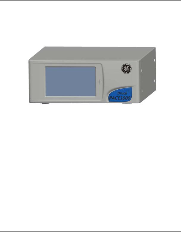
The PACE Pressure Indicator measures both pneumatic and hydraulic pressures and displays, on a colour touch-screen, the measured pressure and instrument status. The touch-screen enables selections and settings in measuring modes. The instrument can be operated remotely through communication interfaces.
Figure 1-1 PACE1000 General view
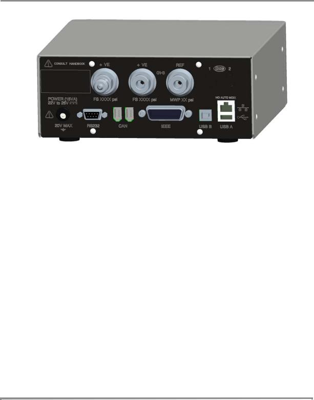
The rear of the instrument houses all the electrical and pressure input connections. The electrical connections provide a power supply, serial and parallel communication interfaces, pressure ports and option ports.
The instrument can be used as follows:
•Free-standing instrument positioned on a horizontal surface.
•Rack-mounted in a standard 19 inch rack using the rack-mount option kit.
•Panel mount using the panel-mount option kit.
K0470 Issue No. 2 |
1 - 1 |
1 Description
Options available for the PACE1000 refer to the SDS.
Information and notes on applications (Ref: Reference and Specification, Section 6) or www.gesensinginspection.com.
K0470 Issue No. 2 |
1 - 2 |

PACE1000 Pressure Indicator User Manual
2 Installation
2.1Packaging
Check the contents of the PACE1000 packaging with the list that follows:
Packaging List - PACE1000
i)PACE1000 Pressure Indicator.
ii)Adaptor, power supply (GE part number 191-370).
iii)User guide and safety instructions, and CD containing the full documentation suite.
iv)Calibration certificate.
2.2Packaging for Storage or Transportation
To store or return the instrument for calibration/repair do the procedures that follow:
1.Pack the instrument (Ref: Reference and Specification, Section 6.13).
2.Return the instrument for calibration/repair complete the return goods procedure (Ref: Reference and Specification, Section 6.12).
2.3Preparation for Use
The instrument can be used as a:
•Free-standing instrument positioned on a horizontal surface
•Panel-mounted using the panel-mount option kit (Ref: Section 2.5)
•Rack-mounted in a standard 19 inch rack using the rack-mount option kit (Ref: Section 2.5).
For free-standing instruments, the feet on the front of the base can be used elevate the instrument to a better viewing angle.
Note: Allow a free flow of air around the instrument, especially at high ambient temperatures.
K0470 Issue No. 2 |
2 - 1 |
2 Installation
2.4Connectioning the Instrument
WARNINGS
TURN OFF THE SOURCE PRESSURE(S) AND CAREFULLY VENT THE PRESSURE LINES BEFORE DISCONNECTING OR CONNECTING THE PRESSURE LINES. PROCEED WITH CARE.
ONLY USE EQUIPMENT WITH THE CORRECT PRESSURE RATING.
BEFORE APPLYING PRESSURE, EXAMINE ALL FITTINGS AND EQUIPMENT FOR DAMAGE. REPLACE ALL DAMAGED FITTINGS AND EQUIPMENT. DO NOT USE ANY DAMAGED FITTINGS AND EQUIPMENT.
Pneumatic Pressure (Figure 2-1)
1.Refer to the SDS for the correct pressure mediums to be used.
2.Connect the Unit Under Test (UUT) to the required connection port.
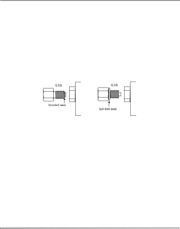
Note: For instruments with NPT connections, use applicable pressure sealing.
recommended method alternative method below 100 bar
Figure 2-1, Sealing Pneumatic Connections
Pneumatic connections
Connection |
|
Input |
G 1/8 |
Reference |
G 1/8 |
For examples of adaptors (Ref: page 2 - 4).
Input Pressure (Figure 2)
1.Make sure the user systems can be isolated and vented.
2.Connect the Unit Under Test (UUT) to the output connection port.
Note: For instruments with NPT connections, use applicable pressure sealing.
K0470 Issue No. 2 |
2 - 2 |
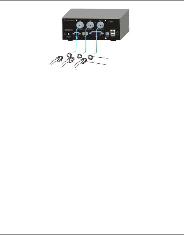
PACE1000 Pressure Indicator User Manual
1) G 1/8 connector
2
1 |
2) Bonded seal |
Figure 2-2, Pneumatic Connections
Installation
The instrument connects to the Unit Under Test.
Input Pressure and Equipment
The pressure should not exceed 1.25 x full-scale or MWP stated on the rear panel of the instrument.
To protect the instrument from over-pressure a suitable protection device (such as a relief valve or bursting disc) must be fitted to prevent over pressurization.
Pneumatic Connection
WARNING
PRESSURE RANGES >210 bar (3000 psi) ARE ONLY RATED FOR HYDRAULIC USE. Cautions
Do not exceed the maximum pressures stated in the appropriate Component Manual for the unit under test.
Reduce pressure at a controlled rate when venting to atmosphere.
Carefully de-pressurize all pipes to atmospheric pressure before disconnecting and connecting to the unit under test.
Connections
1.Switch off the power supply before connecting or disconnecting the instrument.
2.Use the appropriate sealing method for all pressure connections.
K0470 Issue No. 2 |
2 - 3 |

2 Installation
Method of connection G1/8
recommended method
Adaptors
Refer to the data sheet SDS0014 for the range of adaptors.
K0470 Issue No. 2 |
2 - 4 |
 Loading...