


GE
Sensing & Inspection Technologies
Druck PV 62x
pneumatic/hydraulic pressure stations
user manual - K0457
Issue 1
Quick reference data
A1.1
PV 621: Pneumatic pressure station
-950 mbar to 20 bar (-13.5 to 300 psi)
PV 622: Pneumatic pressure station
-950 mbar to 100 bar (-13.5 to 1500 psi)
PV 623: Hydraulic pressure station
0 to 1000 bar (0 to 15000 psi)
A1.2 PV 62x + DPI 620 + PM 620
Recommended pressure modules (PM 620) *
PV 621 models |
25 mbar to 20 bar (0.36 to 300 psi) |
|
|
PV 622 models |
25 mbar to 100 bar (0.36 to 1500 psi) |
|
|
PV 623 models |
70 to 1000 bar (1000 to 15000 psi) |
|
|
Copyright
Trademarks
*Caution: To prevent damage to the PM 620 module, only use it within the specified pressure limit on the label.
A1.3 PV 62x pressure relief valves (PRV)
(Recommended options)
Parts: IO620-PRV-P1 to P5 (Pneumatic)
PV 621 models |
1 to 30 bar (14.5 to 435 psi) |
|
|
PV 622 models |
1 to 100 bar (14.5 to 1500 psi) |
|
|
Parts: IO620-PRV-H1 to H5 (Hydraulic) |
|
PV 623 models |
50 to 1000 bar (725 to 15000 psi) |
|
|
© 2008 General Electric Company. All rights reserved.
All product names are trademarks of their respective companies.
ii

Issue 1
Safety
General warnings
Pressure warnings
Electrical warnings
Before you use the instrument, make sure that you read and understand all the related data. This includes: the applicable local safety procedures, this publication, and the instructions for the accessories/options/equipment you are using it with.
 WARNING
•It is dangerous to ignore the specified limits for the instrument or to use the instrument when it is not in its normal condition. Use the applicable protection and obey all safety precautions.
•Do not use the instrument in locations with explosive gas, vapour or dust. There is a risk of an explosion.
•It is dangerous to attach an external source of pressure to a PV 62x series pressure station. Use only the internal mechanisms to set and control the pressure in the pressure station.
•Some liquid and gas mixtures are dangerous. This includes mixtures that occur because of contamination. Make sure that the equipment is safe to use with the necessary media.
•Pressurized gases and fluids are dangerous. Before you attach or disconnect pressure equipment, safely release all the pressure.
•To prevent a dangerous release of pressure, make sure that all the related pipes, hoses and equipment have the correct pressure rating, are safe to use and are correctly attached.
If you use the DPI 620 calibrator with your pressure station, these warnings are also applicable:
•To prevent electrical shocks or damage to the DPI 620 calibrator, do not connect more than 30V between the terminals, or between the terminals and the ground (earth).
•This instrument uses a Lithium-Polymer (Li-Polymer) battery pack. To prevent an explosion or fire, do not short circuit, do not disassemble, keep it safe from damage.
Continued
[EN] English - K0457 |
Safety iii |
Issue 1
•
•
To prevent an explosion or fire, use only the GE specified battery, power supply and battery charger.
To make sure the display shows the correct data, disconnect the test leads before you set the power to on or change to another measure or source function.
Cautions |
To prevent damage to the instrument, do not let dirt get |
|
into the pressure mechanism. Before you attach |
|
equipment, make sure it is clean. |
|
To prevent damage to the instrument when you move it, |
|
hold the body of the pressure station or use the carry |
|
strap (or specified accessories). |
|
PV 621/PV 622 models only. Before you turn the |
|
pressure/vacuum selector to + or -, release all the |
|
pressure. Sudden high pressure in the pump |
|
mechanism can cause damage. |
|
PV 623 models only. Ice in the pressure mechanism can |
|
cause damage. If the temperature is less than 4°C |
|
(39°F), drain all water from the instrument. |
|
In its normal condition, the PV 623 model contains |
|
hydraulic fluid. To make sure it does not spill out, seal |
|
the system and put it on its side before you install a |
|
PRV. |
|
To prevent damage to the PM 620 module, only use it |
|
within the specified pressure limit on the label. |
|
Before you start an operation or procedure in this publication, |
|
make sure that you have the necessary skills (if necessary, with |
|
qualifications from an approved training establishment). Follow |
|
good engineering practice at all times. |
Marks and symbols on the instrument
Complies with European Union directives |
||
|
|
|
Read the manual |
|
Warning - refer to the |
|
|
manual |
|
|
|
PRV Pressure relief valve (Refer to Chapter 1; item 1 1 1 ) |
||
Do not dispose of this product as household waste. Refer to Chapter 6 (Maintenance procedures).
More marks and symbols are specified in this manual
iv Safety |
K0457 - [EN] English |

Issue 1
Overview
PV 621
PV 622
PV 623
Other module options
Pressure calibrator
DPI 620
PM 620
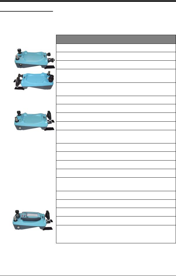
There are three pressure stations in the PV 62x series:
•two pneumatic pressure stations to give you accurate and controlled pressure and vacuum conditions:
PV 621: -950 mbar to 20 bar (-13.5 to 300 psi) version PV 622: -950 mbar to 100 bar (-13.5 to 1500 psi) version
•one hydraulic pressure station to give you accurate and controlled hydraulic pressure conditions:
PV 623: 0 to 1000 bar (15000 psi)
To give the attached equipment overpressure protection, there are pressure relief valves (PRV) available for all the pressure stations; refer to Section 1.5 (Accessories).
The pressure stations are part of a set of hand-held modules that you can quickly put together to include a wide range of calibrator functions.
Pressure calibrator (this user manual): You can use the pressure stations on their own or you can attach the DPI 620 calibrator and a PM 620 module to make a fully integrated pressure calibrator instrument.
Advanced modular calibrator, DPI 620 (user manual - K0449): Optional item. This is a battery-powered instrument for electrical measure and source operations and HART® communications. It also supplies the power and user interface functions for all the add-on modules. You can use the touch-screen to display up to six different parameters.
Pressure modules, PM 620 (this user manual): Optional item. These modules attach to a pressure station (PV 62x) to give the DPI 620 calibrator the necessary pressure measurement functionality. They are fully interchangeable “plug and play” modules with no initial set-up or user calibration.
Software (user manual - K0449): The DPI 620 calibrator includes the following software:
• documenting software |
• HART® communications |
|
software |
Other accessories and options: For part numbers (P/N), refer to Section 1.5 (Accessories).
[EN] English - K0457 |
Overview v |
Issue 1
Summary of functions
PV 621
PV 622
PV 623
Pressure calibrator
This table gives a summary of the available functions with the PV 62x pressure stations.
PV 62x - pressure station functions
Function
Pneumatic pressure stations
*PV 621: Pressure from vacuum (95%) to 20 bar (300 psi);
*PV 622: Pressure from vacuum (95%) to 100 bar (1500 psi)
Selector switch to change the pump operation from pressure generator to vacuum generator
Needle point pressure release valve to control the release of pressure.
Hydraulic pressure station
* PV 623: Hydraulic pressure from 0 to 1000 bar (15000 psi)
Internal hydraulic reservoir: 100 cm3 (6.1 in3)
Self sealing pressure module connection to prevent fluid leaks.
Fast thermal stability for devices attached directly to the pressure test connection (≤ one minute)
All pressure stations
“Quick fit” pressure adaptors for the device under test
** Pressure connection for a PM 620 module
Volume adjuster to give accurate control of pressure conditions.
Latch mechanism to attach the DPI 620 calibrator to make a fully integrated pressure calibrator instrument
**Pressure relief valves (PRV) to give overpressure protection.
**Pressure station + DPI 620 calibrator + PM 620 module
Measure pressure/Leak test
Documenting software
HART® (Highway Addressable Remote Transducer) communications software to set up and calibrate devices that use the HART® field communications protocol.
*Refer to Chapter 7 (Specification)
**Optional item
vi Summary of functions |
K0457 - [EN] English |

|
Issue 1 |
|
|
|
|
About this manual |
This user manual is set up for you to use on a computer or |
|
similar device that has the necessary software to read a |
|
Portable Document Format (PDF) file. |
|
It is supplied as a PDF on a compact disc (CD) but you can |
|
copy or save the PDF onto a computer or similar device that |
|
has the necessary PDF software. |
|
To navigate between related items of information, the user |
|
manual includes cross references and links; for example: |
|
• text cross references: ... Figure 1-1; Table 1-1; Chapter 1; |
|
Section 1.5 (Accessories) |
|
• some (but not all) symbols: 1 1 1 |
|
Note: If you move the PDF software cursor over an item that |
|
has a link, the cursor symbol normally changes. |
|
When you click (or tap) on a link, your PDF software shows the |
|
applicable page. |
[EN] English - K0457 |
About this manual vii |

Issue 1
viii About this manual |
K0457 - [EN] English |

Issue 1
Table of Contents
Quick reference data . . . . . . . . . . . . . . . . . . . . . . . . . . . . . . . . . . . . . . . . . . . . . . . . . . . . . . . .ii Safety. . . . . . . . . . . . . . . . . . . . . . . . . . . . . . . . . . . . . . . . . . . . . . . . . . . . . . . . . . . . . . . . . . . iii Overview . . . . . . . . . . . . . . . . . . . . . . . . . . . . . . . . . . . . . . . . . . . . . . . . . . . . . . . . . . . . . . . . .v Other module options. . . . . . . . . . . . . . . . . . . . . . . . . . . . . . . . . . . . . . . . . . . . . . . . . . . . . . . .v Summary of functions . . . . . . . . . . . . . . . . . . . . . . . . . . . . . . . . . . . . . . . . . . . . . . . . . . . . . . vi About this manual . . . . . . . . . . . . . . . . . . . . . . . . . . . . . . . . . . . . . . . . . . . . . . . . . . . . . . . . . vii
Chapter 1: Instrument parts, accessories and options
1.1 Introduction . . . . . . . . . . . . . . . . . . . . . . . . . . . . . . . . . . . . . . . . . . . . . . . . . . . . . . . . 1-1 1.2 PV 621 models . . . . . . . . . . . . . . . . . . . . . . . . . . . . . . . . . . . . . . . . . . . . . . . . . . . . . . 1-1
1.2.1 Pressure relief valve (PRV) . . . . . . . . . . . . . . . . . . . . . . . . . . . . . . . . . . . . . . 1-2 1.2.2 Test port . . . . . . . . . . . . . . . . . . . . . . . . . . . . . . . . . . . . . . . . . . . . . . . . . . . . . 1-2 1.2.3 Pneumatic pressure release valve . . . . . . . . . . . . . . . . . . . . . . . . . . . . . . . . . 1-2 1.2.4 Volume adjuster . . . . . . . . . . . . . . . . . . . . . . . . . . . . . . . . . . . . . . . . . . . . . . . 1-2 1.2.5 Selector (pressure/vacuum) . . . . . . . . . . . . . . . . . . . . . . . . . . . . . . . . . . . . . . 1-3 1.2.6 Pump (pressure/vacuum) . . . . . . . . . . . . . . . . . . . . . . . . . . . . . . . . . . . . . . . . 1-3
1.3 PV 622 models . . . . . . . . . . . . . . . . . . . . . . . . . . . . . . . . . . . . . . . . . . . . . . . . . . . . . . 1-4
1.3.1 Pressure relief valve (PRV) . . . . . . . . . . . . . . . . . . . . . . . . . . . . . . . . . . . . . . 1-4 1.3.2 Test port . . . . . . . . . . . . . . . . . . . . . . . . . . . . . . . . . . . . . . . . . . . . . . . . . . . . . 1-5 1.3.3 Pneumatic pressure release valve . . . . . . . . . . . . . . . . . . . . . . . . . . . . . . . . . 1-5 1.3.4 Pneumatic refill valve . . . . . . . . . . . . . . . . . . . . . . . . . . . . . . . . . . . . . . . . . . . 1-5 1.3.5 Volume adjuster wheel . . . . . . . . . . . . . . . . . . . . . . . . . . . . . . . . . . . . . . . . . . 1-5 1.3.6 Selector (pressure/vacuum) . . . . . . . . . . . . . . . . . . . . . . . . . . . . . . . . . . . . . . 1-7 1.3.7 Pump (pressure/vacuum) . . . . . . . . . . . . . . . . . . . . . . . . . . . . . . . . . . . . . . . . 1-7
1.4 PV 623 models . . . . . . . . . . . . . . . . . . . . . . . . . . . . . . . . . . . . . . . . . . . . . . . . . . . . . . 1-8
1.4.1 Pressure relief valve (PRV) . . . . . . . . . . . . . . . . . . . . . . . . . . . . . . . . . . . . . . 1-8 1.4.2 Test port . . . . . . . . . . . . . . . . . . . . . . . . . . . . . . . . . . . . . . . . . . . . . . . . . . . . . 1-9 1.4.3 Hydraulic pressure release valve/reservoir access. . . . . . . . . . . . . . . . . . . . . 1-9 1.4.4 Hydraulic refill valve . . . . . . . . . . . . . . . . . . . . . . . . . . . . . . . . . . . . . . . . . . . . 1-9 1.4.5 Volume adjuster wheel . . . . . . . . . . . . . . . . . . . . . . . . . . . . . . . . . . . . . . . . . 1-10
1.5 Accessories . . . . . . . . . . . . . . . . . . . . . . . . . . . . . . . . . . . . . . . . . . . . . . . . . . . . . . . 1-11
[EN] English - K0457 |
Table of Contents viii |

Issue 1
Chapter 2: Pneumatic pressure operation (PV 621)
2.1 Introduction . . . . . . . . . . . . . . . . . . . . . . . . . . . . . . . . . . . . . . . . . . . . . . . . . . . . . . . . 2-1 2.2 Release the pressure. . . . . . . . . . . . . . . . . . . . . . . . . . . . . . . . . . . . . . . . . . . . . . . . . 2-1 2.3 Attach/Remove the device under test . . . . . . . . . . . . . . . . . . . . . . . . . . . . . . . . . . . 2-1
2.3.1 Procedure (to attach) . . . . . . . . . . . . . . . . . . . . . . . . . . . . . . . . . . . . . . . . . . . 2-2 2.3.2 Procedure (to remove) . . . . . . . . . . . . . . . . . . . . . . . . . . . . . . . . . . . . . . . . . . 2-2
2.4 Attach/Adjust a PRV . . . . . . . . . . . . . . . . . . . . . . . . . . . . . . . . . . . . . . . . . . . . . . . . . 2-2
2.4.1 Procedure (to attach) . . . . . . . . . . . . . . . . . . . . . . . . . . . . . . . . . . . . . . . . . . . 2-3 2.4.2 Procedure (to adjust) . . . . . . . . . . . . . . . . . . . . . . . . . . . . . . . . . . . . . . . . . . . 2-3
2.5 Vacuum or pressure operation. . . . . . . . . . . . . . . . . . . . . . . . . . . . . . . . . . . . . . . . . 2-3
2.5.1 Vacuum procedure . . . . . . . . . . . . . . . . . . . . . . . . . . . . . . . . . . . . . . . . . . . . . 2-4 2.5.2 Pressure procedure . . . . . . . . . . . . . . . . . . . . . . . . . . . . . . . . . . . . . . . . . . . . 2-4
Chapter 3: Pneumatic pressure operation (PV 622)
3.1 Introduction . . . . . . . . . . . . . . . . . . . . . . . . . . . . . . . . . . . . . . . . . . . . . . . . . . . . . . . . 3-1 3.2 Release the pressure. . . . . . . . . . . . . . . . . . . . . . . . . . . . . . . . . . . . . . . . . . . . . . . . . 3-1 3.3 Attach/Remove the device under test . . . . . . . . . . . . . . . . . . . . . . . . . . . . . . . . . . . 3-1
3.3.1 Procedure (to attach) . . . . . . . . . . . . . . . . . . . . . . . . . . . . . . . . . . . . . . . . . . . 3-2 3.3.2 Procedure (to remove) . . . . . . . . . . . . . . . . . . . . . . . . . . . . . . . . . . . . . . . . . . 3-2
3.4 Attach/Adjust a PRV . . . . . . . . . . . . . . . . . . . . . . . . . . . . . . . . . . . . . . . . . . . . . . . . . 3-2
3.4.1 Procedure (to attach) . . . . . . . . . . . . . . . . . . . . . . . . . . . . . . . . . . . . . . . . . . . 3-3 3.4.2 Procedure (to adjust) . . . . . . . . . . . . . . . . . . . . . . . . . . . . . . . . . . . . . . . . . . . 3-3
3.5 Vacuum or pressure operation. . . . . . . . . . . . . . . . . . . . . . . . . . . . . . . . . . . . . . . . . 3-3
3.5.1 Vacuum procedure . . . . . . . . . . . . . . . . . . . . . . . . . . . . . . . . . . . . . . . . . . . . . 3-4 3.5.2 Pressure procedure . . . . . . . . . . . . . . . . . . . . . . . . . . . . . . . . . . . . . . . . . . . . 3-4
Chapter 4: Hydraulic pressure operation (PV 623)
4.1 Introduction . . . . . . . . . . . . . . . . . . . . . . . . . . . . . . . . . . . . . . . . . . . . . . . . . . . . . . . . 4-1 4.2 Fill the reservoir. . . . . . . . . . . . . . . . . . . . . . . . . . . . . . . . . . . . . . . . . . . . . . . . . . . . . 4-1 4.3 Release the pressure. . . . . . . . . . . . . . . . . . . . . . . . . . . . . . . . . . . . . . . . . . . . . . . . . 4-2 4.4 Attach/Remove the device under test . . . . . . . . . . . . . . . . . . . . . . . . . . . . . . . . . . . 4-2
4.4.1 Procedure (to attach) . . . . . . . . . . . . . . . . . . . . . . . . . . . . . . . . . . . . . . . . . . . 4-2 4.4.2 Procedure (to remove) . . . . . . . . . . . . . . . . . . . . . . . . . . . . . . . . . . . . . . . . . . 4-3
4.5 Attach/Adjust a PRV . . . . . . . . . . . . . . . . . . . . . . . . . . . . . . . . . . . . . . . . . . . . . . . . . 4-3
4.5.1 Procedure (to attach) . . . . . . . . . . . . . . . . . . . . . . . . . . . . . . . . . . . . . . . . . . . 4-3 4.5.2 Procedure (to adjust) . . . . . . . . . . . . . . . . . . . . . . . . . . . . . . . . . . . . . . . . . . . 4-3
4.6 Pressure operation . . . . . . . . . . . . . . . . . . . . . . . . . . . . . . . . . . . . . . . . . . . . . . . . . . 4-4
4.6.1 Hydraulic pressure procedure. . . . . . . . . . . . . . . . . . . . . . . . . . . . . . . . . . . . . 4-4 4.6.2 Add more hydraulic fluid . . . . . . . . . . . . . . . . . . . . . . . . . . . . . . . . . . . . . . . . . 4-5 4.6.3 Drain hydraulic fluid from the device under test . . . . . . . . . . . . . . . . . . . . . . . 4-5
ix Table of Contents |
K0457 - [EN] English |
Issue 1
4.7 Drain all the hydraulic fluid. . . . . . . . . . . . . . . . . . . . . . . . . . . . . . . . . . . . . . . . . . . . 4-6
4.7.1 Preparation . . . . . . . . . . . . . . . . . . . . . . . . . . . . . . . . . . . . . . . . . . . . . . . . . . . 4-6 4.7.2 Procedure . . . . . . . . . . . . . . . . . . . . . . . . . . . . . . . . . . . . . . . . . . . . . . . . . . . . 4-6
Chapter 5: Pressure calibrator operation (DPI 620)
5.1 Introduction . . . . . . . . . . . . . . . . . . . . . . . . . . . . . . . . . . . . . . . . . . . . . . . . . . . . . . . . 5-1 5.2 Parts and assembly . . . . . . . . . . . . . . . . . . . . . . . . . . . . . . . . . . . . . . . . . . . . . . . . . . 5-1
5.2.1 DPI 620 calibrator parts . . . . . . . . . . . . . . . . . . . . . . . . . . . . . . . . . . . . . . . . . 5-1 5.2.2 PM 620 module parts . . . . . . . . . . . . . . . . . . . . . . . . . . . . . . . . . . . . . . . . . . . 5-2 5.2.3 Assembly instructions . . . . . . . . . . . . . . . . . . . . . . . . . . . . . . . . . . . . . . . . . . . 5-2
5.3 Measure pressure/vacuum . . . . . . . . . . . . . . . . . . . . . . . . . . . . . . . . . . . . . . . . . . . . 5-3
5.3.1 Procedure overview . . . . . . . . . . . . . . . . . . . . . . . . . . . . . . . . . . . . . . . . . . . . 5-3 5.3.2 DPI 620 calibrator: Set the pressure function . . . . . . . . . . . . . . . . . . . . . . . . . 5-4 5.3.3 DPI 620 calibrator: Set the pressure units . . . . . . . . . . . . . . . . . . . . . . . . . . . 5-5 5.3.4 DPI 620 calibrator: Set up a Leak Test. . . . . . . . . . . . . . . . . . . . . . . . . . . . . . 5-5 5.3.5 DPI 620 calibrator: Set the PM 620 module to zero . . . . . . . . . . . . . . . . . . . . 5-6 5.3.6 Example procedure: Gauge/indicator calibration . . . . . . . . . . . . . . . . . . . . . . 5-7 5.3.7 Example procedure: Transmitter calibration . . . . . . . . . . . . . . . . . . . . . . . . . . 5-8 5.3.8 Example procedure: Switch test . . . . . . . . . . . . . . . . . . . . . . . . . . . . . . . . . . . 5-9
Chapter 6: Maintenance procedures
6.1 Introduction . . . . . . . . . . . . . . . . . . . . . . . . . . . . . . . . . . . . . . . . . . . . . . . . . . . . . . . . 6-1 6.2 Clean the unit . . . . . . . . . . . . . . . . . . . . . . . . . . . . . . . . . . . . . . . . . . . . . . . . . . . . . . . 6-1 6.3 Drain the unit (PV 623 models) . . . . . . . . . . . . . . . . . . . . . . . . . . . . . . . . . . . . . . . . . 6-1 6.4 Leak test . . . . . . . . . . . . . . . . . . . . . . . . . . . . . . . . . . . . . . . . . . . . . . . . . . . . . . . . . . . 6-1
6.4.1 Preparation . . . . . . . . . . . . . . . . . . . . . . . . . . . . . . . . . . . . . . . . . . . . . . . . . . . 6-1 6.4.2 Procedure . . . . . . . . . . . . . . . . . . . . . . . . . . . . . . . . . . . . . . . . . . . . . . . . . . . 6-2
Chapter 7: Specification
7.1 PV 62x models . . . . . . . . . . . . . . . . . . . . . . . . . . . . . . . . . . . . . . . . . . . . . . . . . . . . . . 7-1
7.1.1 Pressure data (PV 62x models) . . . . . . . . . . . . . . . . . . . . . . . . . . . . . . . . . . . 7-2
7.2 PM 620 modules. . . . . . . . . . . . . . . . . . . . . . . . . . . . . . . . . . . . . . . . . . . . . . . . . . . . . 7-3
7.2.1 Pressure data (PM 620 modules) . . . . . . . . . . . . . . . . . . . . . . . . . . . . . . . . . . 7-3
Customer service. . . . . . . . . . . . . . . . . . . . . . . . . . . . . . . . . . . . . . . . . . . . . . . . . . . . . Back cover
[EN] English - K0457 |
Table of Contents x |

Issue 1
xi Table of Contents |
K0457 - [EN] English |
1.1Introduction
1.2PV 621 models
Chapter 1: Instrument parts, accessories and options
This chapter gives a description of the different parts of each instrument and the accessories/options available.
3
1
4
2
6
7
8
11
12
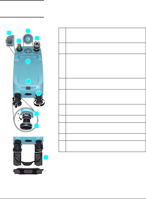
1.Optional accessory: Pressure connection for a pressure relief valve (PRV); see Section 1.2.1. A blanking plug is standard.
2.Test port: Pressure connection (G1/8 or 1/8NPT) to attach the device under test; see Section 1.2.2.
3.Pressure and electrical connections for a PM 620 module.
Seal the pressure connection with a blanking plug (P/N IO620-BLANK) or a PM 620 module that has the correct pressure rating.
4.Pneumatic pressure release valve to release pressure in the system; see Section 1.2.3.
6.Moulded compartment for the DPI 620 calibrator with electrical connections and a mechanism to hold it in position.
7.Push-button mechanism to release the DPI 620 calibrator.
8.Pneumatic volume adjuster; see Section 1.2.4.
11.Pressure/vacuum selector to set the pump operation: pressure (+), vacuum (-); see Section 1.2.5.
12.Pump mechanism; see Section 1.2.6.
13.Carrying strap with a carry handle and a shoulder strap.
Items 5, 9, 10: Not applicable
13
Figure 1-1: General views
[EN] English - K0457 |
Instrument parts, accessories and options 1-1 |
Issue 1
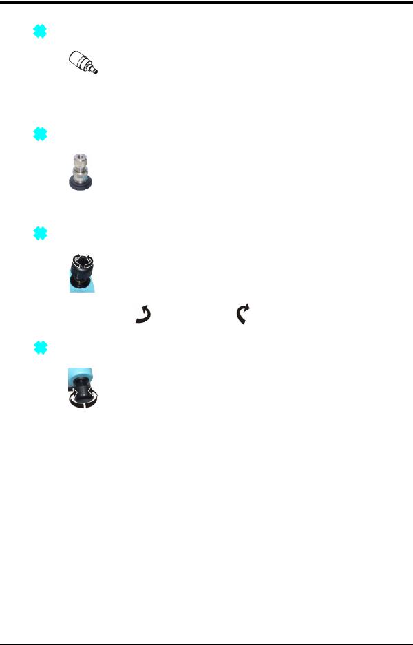
1.2.11 Pressure relief valve (PRV)
To give your attached devices overpressure protection (device under test, PM 620 module), we recommend you use one of our range of optional pneumatic PRVs; see Section 1.5 (Accessories).
To attach or adjust a PRV, see Section 2.4.
1.2.2 2 Test port
To attach the device under test, the test port uses “Quick fit” pressure adaptors; see Section 1.5 (Accessories). These are easy to remove, change and install; see Section 2.3 (Attach/Remove the device under test).
1.2.34 Pneumatic pressure release valve
This is a needle point valve that lets you release the pressure or vacuum, or seal the system. You can also use it to control a change in pressure conditions; for example, to go to or through another test pressure.
: Open |
: Close |
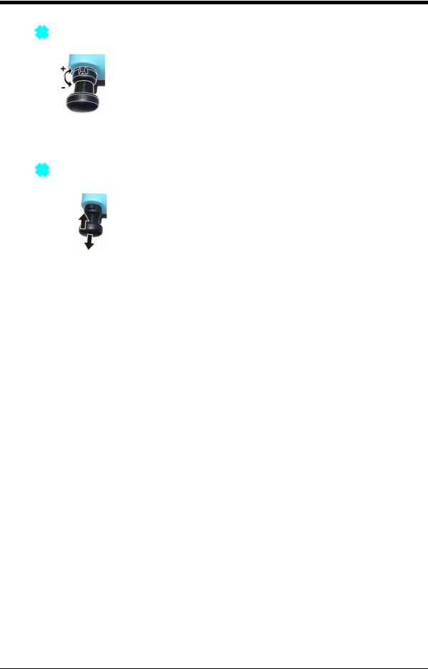
1.2.48 Volume adjuster
This control increases or decreases the pressure/vacuum. Before you seal the system (Section 1.2.3), turn this control to the necessary position:
•
•
for equal adjustment, turn it to the middle of its range
for maximum adjustment, turn it fully clockwise or counterclockwise
When you have set the necessary pressure or vacuum with the pump (Section 1.2.6), use the volume adjuster to make the last adjustments.
1-2 Instrument parts, accessories and options |
K0457 - [EN] English |
Issue 1
1.2.511 Selector (pressure/vacuum)
Caution: Before you turn the pressure/vacuum selector to + or -, release all the pressure. Sudden high pressure in the pump mechanism can cause damage.
This control sets the operation of the instrument (pressure or vacuum). To prevent a pressure leak, turn it fully clockwise or counterclockwise.
+ |
: Pressure |
- |
: Vacuum |
1.2.612 Pump (pressure/vacuum)
When you have set the operation to pressure or vacuum (Section 1.2.5), seal the system (Section 1.2.3) and use the pump to set the necessary pressure or vacuum.
You can then make the last adjustments with the volume adjuster (Section 1.2.4).
[EN] English - K0457 |
Instrument parts, accessories and options 1-3 |

Issue 1
1.3 PV 622 models
13
24
5
6
7
9
11
12
13
Figure 1-2: General views
1.Optional accessory: Pressure connection for a pressure relief valve (PRV); see Section 1.3.1. A blanking plug is standard.
2.Test port: Pressure connection (G1/8 or 1/8NPT) to attach the device under test; see Section 1.3.2.
3.Pressure and electrical connections for a PM 620 module.
Seal the pressure connection with a blanking plug (P/N IO620-BLANK) or a PM 620 module that has the correct pressure rating.
4.Pneumatic pressure release valve to release pressure in the system; see Section 1.3.3.
5.Pneumatic refill valve. Close it to seal off all the pressure and refill the pressure mechanism; see Section 1.3.4.
6.Moulded compartment for the DPI 620 calibrator with electrical connections and a mechanism to hold it in position.
7.Push-button mechanism to release the DPI 620 calibrator.
9.Volume adjuster wheel with fold-in handle; see Section 1.3.5.
11.Pressure/vacuum selector to set the pump operation: pressure (+), vacuum (-); see Section 1.3.6.
12.Pump mechanism; see Section 1.3.7.
13.Carrying strap with a carry handle and a shoulder strap.
Items 8, 10: Not applicable
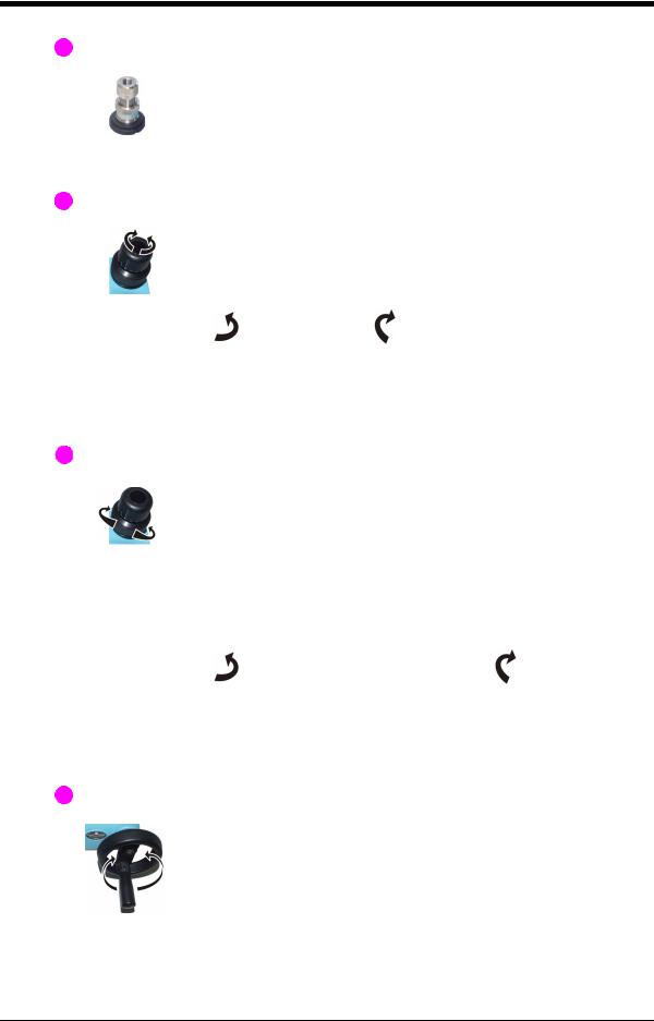
1.3.12 Pressure relief valve (PRV)
To give your attached devices overpressure protection (device under test, PM 620 module), we recommend you use one of our range of optional pneumatic PRVs; see Section 1.5 (Accessories).
To attach or adjust a PRV, see Section 3.4.
1-4 Instrument parts, accessories and options |
K0457 - [EN] English |
Issue 1
1.3.22 Test port
To attach the device under test, the test port uses “Quick fit” pressure adaptors; see Section 1.5 (Accessories). These are easy to remove, change and install; see Section 3.3 (Attach/Remove the device under test).
1.3.34 Pneumatic pressure release valve
This is a needle point valve that lets you release the pressure or vacuum, or seal the system. You can also use it to control a change in pressure conditions; for example, to go to or through another test pressure.
Open |
Close |
Note: To release all the pressure in the system, you must open the refill valve (Section 1.3.4) one turn and then open the pressure release valve one turn.
1.3.45 Pneumatic refill valve
When the refill valve is open, you have full control to increase or decrease the pressure/vacuum with the volume adjuster (Section 1.3.5).
If you increase pressure and the volume adjuster gets to the limit of travel, close the refill valve. This seals off all the pressure in the test port and the pressure module connection. You can then use the pump and volume adjuster to refill the pressure mechanism (Section 1.3.5).
Open (1 turn): Full control |
Close: Refill |
Note: To release all the pressure in the system, you must open the refill valve one turn and then open the pressure release valve (Section 1.3.3) one turn.
1.3.59 Volume adjuster wheel
The refill valve (Section 1.3.4) sets the operation of the Volume adjuster wheel: Full control or refill
[EN] English - K0457 |
Instrument parts, accessories and options 1-5 |
 Loading...