


 Loading...
DOOSAN PUMA MX Series
FANUC Series 31i-Model A5
Programming Examples Manual
Revision 2.1 (07/17/2012) tim.markoski@gmail.com

DISCLAIMER OF WARRANTY:
This user manual and the accompanying files are sold or supplied "as is" and without warranties as to performance of merchantability or any other Warranties whether expressed or implied.
While every effort has been made to verify the accuracy of the content provided, it is the responsibility of those programming and operating Doosan MX Series Multi-Tasking CNC Machining Centers to abide by standards of safe programming, setup and operation of any CNC Machine Tool.
Because the various machine configurations, programming methods, individual work pieces and setup/operator skill levels all effect the actual operation of the machine,
NO WARRANTY OF FITNESS FOR A PARTICULAR PURPOSE IS OFFERED.
The user must assume the entire risk of using the information provided in this manual and accompanying files.
Any typographical errors should be brought to the attention of AmTTech immediately.
South Texas
10010 Houston Oaks Dr. Houston, TX 77064 (832) 912-2000
North Texas
3301 Pleasant Valley Ln. Arlington, TX 76015 (832) 912-2000
Service & Support
Service Support Center: (888) 823-2967
- 1 -
TABLE OF CONTENTS
Standard Turning |
Pg 3 |
|
|
ANSI/ISO Holder Identification |
Pg 4 |
|
Insert Identification |
Pg 5 |
|
B-Axis Spindle Function – G490 |
Pg 9 |
|
Programming Example #1 - Upper |
Pg 10 |
|
Programming Example #2 - Lower |
Pg 13 |
Pinch Turning |
Pg 16 |
|
|
Programming Example #3 – Upper & Lower |
Pg 17 |
Simultaneous Turning |
Pg 20 |
|
|
Programming Example #4 - Upper & Lower w/Part Transfer |
Pg 20 |
Advanced Turning |
Pg 25 |
|
|
B-Axis Spindle Function – G400 |
Pg 26 |
|
Programming Example #5 - Upper |
Pg 28 |
|
Programming Example #6 - Upper |
Pg 31 |
Advanced Drilling |
Pg 34 |
|
|
Programming Example #7 - Upper |
Pg 34 |
|
Programming Example #8 - Upper |
Pg 36 |
|
Programming Example #9 - Upper |
Pg 38 |
|
B-Axis Spindle Tilt Function – G368/G369Upper |
Pg 40 |
|
Programming Example #10 - Upper |
Pg 41 |
Advanced Milling |
Pg 43 |
|
|
Programming Example #11 – Upper (C-Axis/Y-Axis) |
Pg 43 |
|
Programming Example #12 – Upper (C-Axis) |
Pg 46 |
Advanced 5-Axis Operations |
Pg 51 |
|
|
Programming Example #13 – Upper (5-Axis Milling) |
Pg 51 |
|
Doosan TCP Mode for 5-Axis Machining G700/G701 |
Pg 53 |
|
CAM System Post-Processor Information |
Pg 55 |
|
APT Cutter Location File Generated by CAM System |
Pg 56 |
|
NC Code File Generated by CAM System Post-Processor |
Pg 61 |
Miscellaneous |
Pg 66 |
|
|
Servo Driven Tail Stock |
Pg 66 |
|
Macro-B OD Jaw Program |
Pg 66 |
- 2 -
DOOSAN PUMA MX Series – Standard Turning
The Doosan Puma MX Series is a powerful Multi-Task Machining Center.
Its core is built upon the concepts a standard CNC Turning Center.
As such, it handles standard CNC Turning quite well.
The basic differences in programming are not in the tool path motion but in the following:
By standardizing the NC Code data in these areas, we can come up with a basic skeleton or outline for all machining operations. This standardization will aid in the creation of a Post-Processor for any given CAM system that a user may have for generating NC programs.
As ANSI/ISO Stick Tooling is well established for CNC Turning Operations, the first four examples in this user manual will be using this standard stick tooling along with the proper CAPTO® C6 holder and adapters for that tooling.
As all Doosan Puma MX Series Multi-Task Machining Center have the common element of the Nutating B-Axis Head, our first standard turning example will be done using the B-Axis Head for all operations. We will then progress to using the Lower Turret independently and then integrate it into synchronized operations using both the Upper B-Axis Head and the Lower Turret.
- 3 -

- 4 -

Insert Designation Chart
Shape |
(e.g. "CNMG432" / "CCMT32.51") |
|||
|
|
|
|
|
Code Letter |
|
Description |
Diagram |
Nose Angle |
A |
|
85° parallelogram |
|
85° |
|
|
|
|
|
B |
|
82° parallelogram |
|
82° |
|
|
|
|
|
C |
|
80° diamond |
|
80° |
|
|
|
|
|
D |
|
55° diamond |
|
55° |
|
|
|
|
|
E |
|
75° diamond |
|
75° |
|
|
|
|
|
H |
|
hexagon |
|
120° |
|
|
|
|
|
K |
|
55° parallelogram |
|
55° |
|
|
|
|
|
L |
|
rectangle |
|
90° |
|
|
|
|
|
M |
|
86° diamond |
|
86° |
|
|
|
|
|
N |
|
55° parallelogram |
|
55° |
|
|
|
|
|
O |
|
octagon |
|
135° |
|
|
|
|
|
P |
|
pentagon |
|
108° |
|
|
|
|
|
R |
|
round |
|
full radius |
|
|
|
|
|
S |
|
square |
|
90° |
|
|
|
|
|
T |
|
triangle |
|
60° |
|
|
|
|
|
V |
|
35° diamond |
|
35° |
|
|
|
|
|
W |
|
trigon |
|
80° |
|
|
|
|
|
X |
|
sp. parallelogram |
|
85° |
|
|
|
|
|
Clearance or Relief Angle (e.g. "CNMG432" / "CCMT32.51")
Code Letter |
Angle |
Diagram |
N |
0° |
|
A 3°
B 5°
C 7°
P 11°
D 15°
E 20°
F 25°
G 30°
- 5 -

|
|
|
Tolerance |
(e.g. "CNMG432" / "CCMT32.51") |
|
|
||||
|
|
|
|
|
|
|
|
|
|
|
|
Code |
Cornerpoint |
Thickness |
|
Inscribed |
Cornerpoint |
Thickness |
Inscribed |
|
|
|
Letter |
(inches) |
(inches) |
|
Circle (in) |
(mm) |
(mm) |
Circle (mm) |
|
|
|
|
|
|
|
|
|
|
|
|
|
|
A |
.0002" |
.001" |
|
.001" |
.005mm |
.025mm |
.025mm |
|
|
|
C |
.0005" |
.005" |
|
.001" |
.013mm |
.025mm |
.025mm |
|
|
|
E |
.001" |
.001" |
|
.001" |
.025mm |
.025mm |
.025mm |
|
|
|
F |
.0002" |
.005" |
|
.0005" |
.005mm |
.025mm |
.013mm |
|
|
|
G |
.001" |
.001" |
|
.001" |
.025mm |
.13mm |
.025mm |
|
|
|
H |
.0005" |
.001" |
|
.0005" |
.013mm |
.025mm |
.013mm |
|
|
|
J |
.002" |
.001" |
|
.002-.005" |
.005mm |
.025mm |
.05-.13mm |
|
|
|
K |
.0005" |
.001" |
|
.002-.005" |
.013mm |
.025mm |
.05-.13mm |
|
|
|
L |
.001" |
.001" |
|
.002-.005" |
.025mm |
.025mm |
.05-.13mm |
|
|
|
M |
.002-.005" |
.005" |
|
.002-.005" |
.05-.13mm |
.13mm |
.05-.15mm |
|
|
|
U |
.005-.012" |
.001" |
|
.005-.010" |
.06-.25mm |
.13mm |
.08-.25mm |
|
|
|
|
|
Hole / Chipbreaker |
(e.g. "CNMG432" / "CCMT32.51") |
|
|
||||
|
|
|
|
|
|
|
|
|||
Code Letter |
|
Diagram |
Hole |
Hole Shape |
|
Chipbreaker Type |
|
|||
|
A |
|
|
Yes |
Cylindrical |
|
None |
|
|
|
|
|
|
|
|
|
|
|
|
||
|
B |
|
|
Yes |
70-90° double countersink |
None |
|
|
||
|
|
|
|
|
|
|
|
|
|
|
|
D |
|
|
Yes |
Cylindrical |
|
None |
|
|
|
|
E |
|
|
No |
|
|
|
None |
|
|
|
F |
|
|
No |
|
|
|
Double-sided |
|
|
|
G |
|
|
Yes |
Cylindrical |
|
Double-sided |
|
|
|
|
H |
|
|
Yes |
70-90° single countersink |
Single-sided |
|
|
||
|
|
|
|
|
|
|
|
|
||
|
M |
|
|
Yes |
Cylindrical, or dbl countersink |
Single-sided |
|
|
||
|
|
|
|
|
|
|
|
|
|
|
|
N |
|
|
No |
|
|
|
None |
|
|
|
|
|
|
|
|
|
|
|
||
|
P |
|
|
Yes |
Cylindrical |
|
Hi-double positive |
|
||
|
|
|
|
|
|
|
|
|
||
|
Q |
|
|
Yes |
40-60° double countersink |
None |
|
|
||
|
R |
|
|
No |
|
|
|
Single-sided |
|
|
|
S |
|
|
Yes |
Cylindrical |
|
Hi-double positive |
|
||
|
|
|
|
|
|
|
|
|
||
|
T |
|
|
Yes |
40-60° double countersink |
Single-sided |
|
|
||
|
|
|
|
|
|
|
|
|
||
|
U |
|
|
Yes |
40-60° double countersink |
Double-sided |
|
|
||
|
W |
|
|
Yes |
40-60° double countersink |
None |
|
|
||
|
|
|
|
|
|
|
|
|
||
|
Z |
|
|
Yes |
Cylindrical |
|
Double-sided hi-double positive |
|
||
|
|
|
|
|
|
|
|
|
|
|
- 6 -

|
|
|
Size (e.g. "CNMG432" / "CCMT32.51") |
|
|
|
|||
ANSI |
Inscribed Circle Size |
ISO Code No. (metric cutting edge length) by shape code letter of insert |
|||||||
Code No. |
decimal in. |
fractional in. |
C |
D |
R |
S |
T |
V |
W |
0.5 |
.0625" |
1/16 |
|
|
|
|
|
|
|
1.2 |
.15625" |
5/32 |
|
|
|
|
|
|
|
1.5 |
.1875" |
3/16 |
04 (4mm) |
5mm |
04 (4mm) |
04 (4mm) |
8mm |
8mm |
S3 |
1.8 |
.21875" |
7/32 |
|
|
|
|
|
|
|
2 |
.25" |
1/4 |
06 (6mm) |
07 (7mm) |
06 (6mm) |
06 (6mm) |
11 (11mm) |
11 (11mm) |
04 (4mm) |
2.5 |
.3125" |
5/16 |
08 (8mm) |
9mm |
07 (7mm) |
07 (7mm) |
13 (13mm) |
13 (13mm) |
05 (5mm) |
3 |
.375" |
3/8 |
09 (9mm) |
11 (11mm) |
09 (9mm) |
09 (9mm) |
16 (16mm) |
16 (16mm) |
06 (6mm) |
3.5 |
.4375" |
7/16 |
11mm |
13mm |
11 (11mm) |
11 (11mm) |
19 (19mm) |
19mm |
7mm |
4 |
.5" |
1/2 |
12 (12mm) |
15 (15mm) |
12 (12mm) |
12 (12mm) |
22 (22mm) |
22 (22mm) |
08 (8mm) |
4.5 |
.5625" |
9/16 |
14mm |
17mm |
14 (14mm) |
14 (14mm) |
24mm |
24mm |
9mm |
5 |
.625" |
5/8 |
16 (16mm) |
19 (9mm) |
15 (15mm) |
15 (15mm) |
27 (27mm) |
27 (27mm) |
10 (10mm) |
5.5 |
.6875" |
11/16 |
17mm |
21mm |
17 (17mm) |
17 (17mm) |
30mm |
30mm |
11mm |
6 |
.75" |
3/4 |
19 (19mm) |
23 (23mm) |
19 (19mm) |
19 (19mm) |
33 (33mm) |
33 (33mm) |
13 (13mm) |
6.5 |
.8125" |
13/16 |
|
|
|
|
|
|
|
7 |
.875" |
7/8 |
22mm |
27mm |
22 (22mm) |
22 (22mm) |
38mm |
38mm |
15mm |
8 |
1" |
1 |
25 (25mm) |
31 (31mm) |
25 (25mm) |
25 (25mm) |
44 (44mm) |
44 (44mm) |
17 (17mm) |
10 |
1.25" |
1-1/4 |
32 (32mm) |
38mm |
31 (31mm) |
31 (31mm) |
54 (54mm) |
54 (54mm) |
21 (21mm) |
|
1.26" |
|
|
|
32 (32mm) |
|
|
|
|
Thickness (e.g. "CNMG432" / "CCMT32.51")
ANSI |
ISO |
Decimal |
Fractional |
Millimeter |
Code No. |
Code No. |
Value |
Value |
Value |
1 |
01 |
0.0625" |
1/16 |
1.59mm |
|
T1 |
0.078" |
5/64 |
1.98mm |
1.5 |
02 |
0.094" |
3/32 |
2.38mm |
|
T2 |
0.109" |
7/64 |
2.78mm |
2 |
03 |
0.125" |
1/8 |
3.18mm |
2.5 |
T3 |
0.156" |
5/32 |
3.97mm |
3 |
04 |
0.187" |
3/16 |
4.76mm |
|
05 |
0.219" |
7/32 |
5.56mm |
4 |
06 |
0.25" |
1/4 |
6.35mm |
5 |
07 |
0.313" |
5/16 |
7.9mm |
6 |
09 |
0.375" |
3/8 |
9.53mm |
8 |
|
0.5" |
1/2 |
12.7mm |
|
Radius |
(e.g. "CNMG432" / "CCMT32.51") |
|
|||
ANSI |
ISO |
|
Decimal |
Fractional |
|
Millimeter |
Code No. |
Code No. |
|
Value |
Value |
|
Value |
Null |
Null |
|
Wiper flat |
Wiper flat |
|
Wiper flat |
V |
M0 |
|
0 |
0 |
|
0 |
0.2 |
00 |
|
0.004" |
|
|
0.1mm |
X |
|
|
0.004" |
|
|
0.1mm |
0.5 |
|
|
0.008" |
|
|
0.2mm |
0 |
00 |
|
0.008" |
|
|
0.2mm |
Y |
|
|
0.008" |
|
|
0.2mm |
1 |
04 |
|
0.016" |
1/64 |
|
0.4mm |
|
05 |
|
0.020" |
|
|
0.5mm |
2 |
08 |
|
0.031" |
1/32 |
|
0.8mm |
|
10 |
|
0.040" |
|
|
1.02mm |
3 |
12 |
|
0.047" |
3/64 |
|
1.2mm |
4 |
16 |
|
0.062" |
1/16 |
|
1.6mm |
5 |
20 |
|
0.078" |
5/64 |
|
2mm |
6 |
24 |
|
0.094" |
3/32 |
|
2.4mm |
7 |
29 |
|
0.109" |
7/64 |
|
2.9mm |
8 |
32 |
|
0.125" |
1/8 |
|
3.2mm |
- 7 -

Wiper Lead Angle |
(e.g. "SEKN42AFTN") |
|||||||||
|
|
Code Letter |
|
Angle |
|
|
|
|
||
|
|
|
|
A |
|
45° |
|
|
|
|
|
|
|
|
D |
|
60° |
|
|
|
|
|
|
|
|
K |
|
60° |
|
|
|
|
|
|
|
|
E |
|
75° |
|
|
|
|
|
|
|
|
L |
|
75° |
|
|
|
|
|
|
|
|
P |
|
0° |
|
|
|
|
Wiper Clearance Angle |
(e.g. "SEKN42AFTN") |
|||||||||
|
|
Code Letter |
|
Angle |
|
|
|
|
||
|
|
|
|
C |
|
7° |
|
|
|
|
|
|
|
|
D |
|
15° |
|
|
|
|
|
|
|
|
E |
|
20° |
|
|
|
|
|
|
|
|
F |
|
25-26° |
|
|
|
|
|
|
|
|
G |
|
30° |
|
|
|
|
|
|
|
|
N |
|
0° |
|
|
|
|
|
|
|
|
P |
|
11° |
|
|
|
|
Cutting Edge Preparation |
(e.g. "SEKN42AFTN") |
|||||||||
|
|
Code Letter |
Edge Preparation |
|
|
|||||
|
|
|
F |
sharp |
|
|
||||
|
|
|
E |
honed |
|
|
||||
|
|
|
T |
T-land |
|
|
||||
|
|
|
S |
honed T-land |
|
|
||||
|
|
|
X |
special chamfer |
|
|
||||
Cutting Direction (e.g. "SEKN42AFTN") |
||||||||||
Code Letter |
|
Direction |
|
|
|
|
|
|||
R |
|
right-hand cutting only |
||||||||
L |
|
left-hand cutting only |
||||||||
N |
|
both right-hand and left-hand cutting |
||||||||
- 8 -

B-Axis Spindle Function - G490
Automatic Milling Spindle Orientation (G490)
The B-Axis Head Spindle contains a curvic-coupling on the front face.
This allows for the possible indexing of the milling spindle in 30˚ increments.
The Doosan Puma MX series has two functions in commanding for milling spindle orientation.
The G490 function automatically unclamps the milling spindle and orients to the designated degree of rotation. After orientation, the milling spindle is automatically clamped.
The other function (M279) is needed to command unclamping (M101) for the milling spindle before commanding orientation and to command clamping (M100) after commanding orientation. But this is only for maintenance by an authorized Service Engineer.
Command Format
G490 S
G490 : automatic milling spindle orientation command
S : orientation degree of milling spindle
S0 |
→ 0˚ |
S300 |
→ 30˚ |
S1800 |
→ 180˚ |
S3600 |
→ 360˚ |
Note:
G490 S0 is automatically invoked during a Tool Change Sequence.
It is not required to command G49 S0 prior to a Tool Change Sequence. However, all examples using the B-Axis Head will show this commanded explicitly for clarity.
- 9 -
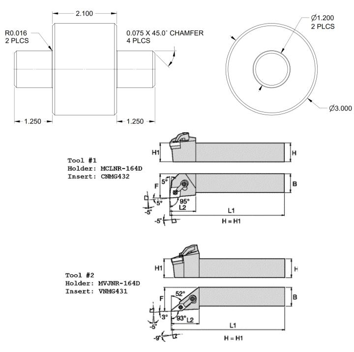
EXAMPLE #1 – STANDARD TURNING – UPPER UNIT ONLY
MATERIAL |
: |
AISI 4140 ALLOY STEEL - 275 HB |
||
STOCK |
: |
3.5 |
DIA ROUND BAR X 4.85 LONG |
|
PROJECTION: |
2.5 |
MINIMUM FROM JAW FACE |
(2) |
|
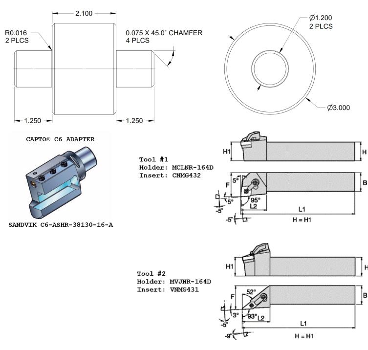
ADAPTERS |
: |
SANDVIK C6-ASHR-38130-16-A |
||
HOLDERS |
: |
MCLNR-164D (1), MVJNR-164D |
(1) |
|
INSERTS |
: |
CNMG-432 (1), VNMG-431 (1) |
|
|
SPINDLE |
: |
LEFT MAIN |
|
|
WORK COORD: |
G54 |
|
Z0.0 = FINISHED FACE |
|
ORIGIN |
: |
X0.0 = SPINDLE CENTERLINE, |
||
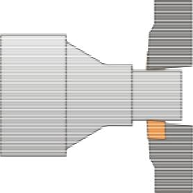
PROCESS |
: |
FACE, ROUGH & FINISH TURN HALF OF PART |
||
- 10 -
%
O0001(MX-EXAMPLE #1 – UPPER UNIT ONLY)
(PREPARATION FOR START OF PROGRAM)
(INITIALIZE - RAPID, ZX PLANE, TNR COMP CANCEL, TLO CANCEL, CYCLE CANCEL, UPR FEED) N1 G00 G18 G40 G49 G80 G99
N2 G00 G28 U0.0 V0.0 (ZERO RETURN X-AXIS & Y-AXIS)
N3 G00 G28 W0.0 (ZERO RETURN Z-AXIS)
N4 G00 G28 B0.0 (ZERO RETURN B-AXIS)
N5 G490 S0 (EXPLICIT B-AXIS SPINDLE ORIENTATION FOR TOOL CHANGE) N6 G00 B-90.0 (EXPLICIT B-AXIS POSITIONING FOR TOOL CHANGE)
N7 M01
(PREPARATION FOR START OF OPERATION)
N8 G54 (WORK COORDINATE SELECTION)
N9 M06 T01001 (SANDVIK C6-ASHR-38130-16-A - MCLNR-164D - CNMG432) N10 T02000 (STAGE NEXT TOOL)
N11 G490 S0 (EXPLICIT B-AXIS SPINDLE ORIENTATION FOR TOOL)
N12 G00 G28 W0.0 (ZERO RETURN Z-AXIS)
N13 G00 G28 B0.0 (ZERO RETURN B-AXIS)
N14 M138 (SHOWER BED COOLANT ON)
N15 M126 (COOLANT THROUGH TOOL ON)
N16 M34 (LEFT SPINDLE C-AXIS MODE OFF)
N17 M261 (SPINDLE WINDING LOW - REPLACES M41)
N18 G50 S2500 (MAXIMUM RPM CAP)
N19 G96 S500 M03 P11 (CONSTANT CUTTING SPEED MODE - 500 FPM - LEFT SPINDLE CLOCKWISE)
(FACE = ROUGH & FINISH) N20 G00 X3.7 Z0.01
N21 G01 X-0.0625 F0.018
N22 G00 Z0.11
N23 X3.7
N24 Z0.0
N25 G01 X-0.0625 F0.01
N26 G00 Z0.1
(OD CANNED ROUGH) N27 G00 X3.5
N28 G00 Z0.0615
N29 G71 U0.125 R0.03
N30 G71 P31 Q40 U0.02 W0.01 F0.018
N31 G00 X0.8903
N32 G01 X1.1817 Z-0.0842
N33 G03 X1.2 Z-0.1063 R0.0313
N34 G01 Z-1.125
N35 G01 X2.7875
N36 G03 X2.8317 Z-1.1342 R0.0313
N37 G01 X2.9817 Z-1.2092
N38 G03 X3.0 Z-1.2313 R0.0313
N39 G01 Z-2.225
N40 G01 X3.5
N41 G00 Z0.1
(TOOL CHANGE PREPARATION)
N42 G00 G28 U0.0 V0.0 (ZERO RETURN X-AXIS & Y-AXIS)
N43 G00 G28 W0.0 (ZERO RETURN Z-AXIS)
N44 G00 G28 B0.0 (ZERO RETURN B-AXIS)
N45 T01000 (CANCEL OFFSET FOR CURRENT TOOL)
N46 M139 (SHOWER BED COOLANT OFF)
N47 M127 (COOLANT THROUGH TOOL OFF)
N48 M05 P11 (LEFT SPINDLE STOP)
N49 G490 S0 (EXPLICIT B-AXIS SPINDLE ORIENTATION FOR TOOL CHANGE) N50 G00 B-90.0 (EXPLICIT B-AXIS POSITIONING FOR TOOL CHANGE)
N51 M01
- 11 -
(PREPARATION FOR START OF OPERATION)
N52 G54 (WORK COORDINATE SELECTION)
N53 M06 T02002 (SANDVIK C6-ASHR-38130-16-A - MVJNR-164D - VNMG431) N54 T01000 (STAGE NEXT TOOL)
N55 G490 S0 (EXPLICIT B-AXIS SPINDLE ORIENTATION FOR TOOL)
N56 G00 G28 W0.0 (ZERO RETURN Z-AXIS)
N57 G00 G28 B0.0 (ZERO RETURN B-AXIS)
N58 M126 (COOLANT THROUGH TOOL ON)
N59 M34 (LEFT SPINDLE C-AXIS MODE OFF)
N60 M262 (SPINDLE WINDING HIGHREPLACES M42)
N61 G50 S2500 (MAXIMUM RPM CAP)
N62 G96 S600 M03 P11 (CONSTANT CUTTING SPEED MODE - 600 FPM - LEFT SPINDLE CLOCKWISE)
(OD FINISH)
N63 G00 X3.5 Z0.1
N64 X1.0408 Z0.0661
N65 G01 X0.9701 Z0.0308 F0.006
N66 X1.1908 Z-0.0796
N67 G03 X1.2 Z-0.0906 R0.0156
N68 G01 Z-1.125
N69 X2.8187
N70 G03 X2.8408 Z-1.1296 R0.0156
N71 G01 X2.9908 Z-1.2046
N72 G03 X3.0 Z-1.2156 R0.0156
N73 G01 Z-2.205
N74 X3.0707 Z-2.1697
N75 G00 X3.5 Z0.1
(END PROGRAM/TOOL CHANGE PREPARATION)
N76 G00 G28 U0.0 V0.0 (ZERO RETURN X-AXIS & Y-AXIS)
N77 G00 G28 W0.0 (ZERO RETURN Z-AXIS)
N78 G00 G28 B0.0 (ZERO RETURN B-AXIS)
N79 T02000 (CANCEL OFFSET FOR CURRENT TOOL)
N80 M139 (SHOWER BED COOLANT OFF)
N81 M127 (COOLANT THROUGH TOOL OFF)
N82 M05 P11 (LEFT SPINDLE STOP)
N83 G490 S0 (EXPLICIT SPINDLE ORIENTATION FOR TOOL CHANGE)
N84 G00 B-90.0 (EXPLICIT B-AXIS POSITIONING FOR TOOL CHANGE)
N85 M30
%
- 12 -
EXAMPLE #2 – STANDARD TURNING – LOWER UNIT ONLY
MATERIAL |
: |
AISI 4140 ALLOY STEEL - 275 HB |
|
STOCK |
: |
3.5 |
DIA ROUND BAR X 4.85 LONG |
PROJECTION: |
2.5 |
MINIMUM FROM JAW FACE |
|
ADAPTERS |
: |
N/A |
|
HOLDERS |
: |
MCLNR-164D (1), MVJNR-164D (1) |
|
INSERTS |
: |
CNMG-432 (1), VNMG-431 (1) |
|
SPINDLE |
: |
LEFT MAIN |
|
WORK COORD: |
G54 |
|
|
ORIGIN |
: |
X0.0 = SPINDLE CENTERLINE, Z0.0 = FINISHED FACE |
|
PROCESS |
: |
FACE, ROUGH & FINISH TURN HALF OF PART |
|
- 13 -
%
O0002(MX-EXAMPLE #2 - LOWER)
(PREPARATION FOR START OF PROGRAM)
(INITIALIZE - RAPID, ZX PLANE, TNR COMP CANCEL, CYCLE CANCEL, UPR FEED) N1 G00 G18 G40 G80 G99
N2 G00 G28 U0.0 (ZERO RETURN X-AXIS)
N3 G00 G28 W0.0 (ZERO RETURN Z-AXIS)
(PREPARATION FOR START OF OPERATION)
N4 G54 (WORK COORDINATE SELECTION)
N5 T01001 (MCLNR-164D - CNMG432)
N6 M138 (SHOWER BED COOLANT ON)
N7 M08 (COOLANT ON)
N8 M34 (LEFT SPINDLE C-AXIS MODE OFF)
N9 M261 (SPINDLE WINDING LOW - REPLACES M41)
N10 G50 S2500 (MAXIMUM RPM CAP)
N11 G96 S500 M03 P11 (CONSTANT CUTTING SPEED MODE - 500 FPM - LEFT SPINDLE CLOCKWISE)
(FACE = ROUGH & FINISH) N12 G00 X3.7 Z0.01
N13 G01 X-0.0625 F0.018
N14 G00 Z0.11
N15 X3.7
N16 Z0.
N17 G01 X-0.0625 F0.01
N18 G00 Z0.1
(OD CANNED ROUGH) N19 G00 X3.5
N20 G00 Z0.0615
N21 G71 U0.125 R0.03
N22 G71 P23 Q32 U0.02 W0.01 F0.018
N23 G00 X0.8903
N24 G01 X1.1817 Z-0.0842
N25 G03 X1.2 Z-0.1063 R0.0313
N26 G01 Z-1.125
N27 G01 X2.7875
N28 G03 X2.8317 Z-1.1342 R0.0313
N29 G01 X2.9817 Z-1.2092
N30 G03 X3.0 Z-1.2313 R0.0313
N31 G01 Z-2.225
N32 G01 X3.5
N33 G00 Z0.1
(TOOL CHANGE PREPARATION)
N34 G00 G28 U0.0 (ZERO RETURN X-AXIS)
N35 G00 G28 W0.0 (ZERO RETURN Z-AXIS)
N36 T01000 (CANCEL OFFSET FOR CURRENT TOOL)
N37 M139 (SHOWER BED COOLANT OFF)
N38 M09 (COOLANT THROUGH TOOL OFF)
N39 M05 P11 (LEFT SPINDLE STOP)
N40 M01
(PREPARATION FOR START OF OPERATION)
N41 G54 (WORK COORDINATE SELECTION)
N42 T02002 (MVJNR-164D - VNMG431)
N43 M08 (COOLANT ON)
N44 M34 (LEFT SPINDLE C-AXIS MODE OFF)
N45 M262 (SPINDLE WINDING HIGHREPLACES M42)
N46 G50 S2500 (MAXIMUM RPM CAP)
N47 G96 S600 M03 P11 (CONSTANT CUTTING SPEED MODE - 600 FPM - LEFT SPINDLE CLOCKWISE)
- 14 -
(OD FINISH)
N48 G00 X3.5 Z0.1
N49 X1.0408 Z0.0661
N50 G01 X0.9701 Z0.0308 F0.006
N51 X1.1908 Z-0.0796
N52 G03 X1.2 Z-0.0906 R0.0156
N53 G01 Z-1.125
N54 X2.8187
N55 G03 X2.8408 Z-1.1296 R0.0156
N56 G01 X2.9908 Z-1.2046
N57 G03 X3.0 Z-1.2156 R0.0156
N58 G01 Z-2.205
N59 X3.0707 Z-2.1697
N60 G00 X3.5 Z0.1
(END PROGRAM/TOOL CHANGE PREPARATION)
N61 G00 G28 U0.0 (ZERO RETURN X-AXIS)
N62 G00 G28 W0.0 (ZERO RETURN Z-AXIS)
N63 T02000 (CANCEL OFFSET FOR CURRENT TOOL)
N64 M139 (SHOWER BED COOLANT OFF)
N65 M09 (COOLANT THROUGH TOOL OFF)
N66 M05 P11 (LEFT SPINDLE STOP)
N67 T12000 (INDEX TO EMPTY TOOL FOR LOWER TURRET CHUCK CLEARANCE)
N68 G00 G54 Z0.0 (POSITION LOWER TURRET FOR WORKING ENVELOPE CLEARANCE) N69 M30
%
- 15 -
PINCH TURNING – SYNCHRONIZED UPPER & LOWER
Pinch Turning is a way to employ 2 independent and opposing tools on a CNC lathe in order to cut more quickly. When Pinch Turning, one tool follows 180° of spindle rotation behind the other. Each opposing tool is only engaged in the cut for 180° of spindle rotation.
The Doosan Puma MX Series T & ST configurations fully support Pinch Turning.
The feed rate that is calculated for each tool is doubled.
The tools cut at the same time but are 180° out of phase so that the amount of time needed for the Pinch Turned Operation is 50% less than a standard turning operation.
The tools used in Pinch Turning must be identical in configuration.
The opposing tools should both share the same orientation (Right or Left Handed), clearance and relief angles, and most importantly, the inserts used must be identical.
Pinch Turning is also referred to as Balanced Turning. It can be used for either roughing or finishing.
With Pinch Turning, both the opposing tools use the same programmed path. However, each program is independent and is a separate control system.
These different control systems are typical classified as Upper & Lower and are synchronized during automatic operation. This synchronization is achieved by the use of Wait Codes (M900-M999) that are placed strategically within the NC code. A Wait Code is included on a line of NC Code where we wish to begin the synchronization. The same wait code is placed at the corresponding point in the NC Code for the opposing tool. When the Upper and Lower Control Systems reach the same point, both Upper and Lower Tools will begin their motion at the same time.
If either Control System reaches a Wait Code before the other Control System, that Control System will wait for the other system to “catch up” before beginning synchronized operations.
- 16 -
EXAMPLE #3 – STANDARD TURNING – SYNCHRONIZED UPPER & LOWER
MATERIAL |
: |
AISI 4140 ALLOY STEEL - 275 HB |
||
STOCK |
: |
3.5 |
DIA ROUND BAR X 4.85 LONG |
|
PROJECTION: |
2.5 |
MINIMUM FROM JAW FACE |
(2) |
|
ADAPTERS |
: |
SANDVIK C6-ASHR-38130-16-A |
||
HOLDERS |
: |
MCLNR-164D (2), MVJNR-164D |
(2) |
|
INSERTS |
: |
CNMG-432 (2), VNMG-431 (2) |
|
|
SPINDLE |
: |
LEFT MAIN |
|
|
WORK COORD: |
G54 |
|
Z0.0 = FINISHED FACE |
|
ORIGIN |
: |
X0.0 = SPINDLE CENTERLINE, |
||
PROCESS |
: |
FACE WITH UPPER, PINCH TURN ROUGH & FINISH TURN HALF OF PART |
||
- 17 -
% |
|
|
|
|
|
|
|
|
|
|
% |
|
|
|
|
|
|
|
|
|
O0003(MX-EXAMPLE #3 - UPPER) |
|
O0003(MX-EXAMPLE #3 - LOWER) |
|
|||||||||||||||||
(PINCH TURN SYNCHRONIZED WITH LOWER TURRET) |
(PINCH TURN SYNCHRONIZED WITH B-AXIS HEAD) |
|||||||||||||||||||
N1 |
G00 |
G18 |
G40 |
G49 |
G80 |
G99 |
|
N1 |
G00 |
G18 |
G40 |
G80 |
G99 |
|
|
|||||
N2 |
G00 |
G28 |
U0.0 |
|
V0.0 |
|
|
N2 |
G00 |
G28 |
U0.0 |
|
|
|
|
|
||||
N3 |
G00 |
G28 |
W0.0 |
|
|
|
|
|
N3 |
G00 |
G28 |
W0.0 |
|
|
|
|
|
|||
N4 |
G00 |
G28 |
B0.0 |
|
|
|
|
|
N4 |
G54 |
|
|
|
|
|
|
|
|
||
N5 |
G490 |
|
S0 |
|
|
|
|
|
|
|
|
|
|
|
|
|
|
|
||
N6 G00 B-90.0 |
|
|
|
|
|
N5 T01001 |
|
|
|
|
|
|
|
|||||||
N7 |
M01 |
|
|
|
|
|
|
|
|
|
N6 |
M138 |
|
|
|
|
|
|
|
|
N8 |
G54 |
|
|
|
|
|
|
|
|
|
N7 |
M08 |
|
|
|
|
|
|
|
|
N9 |
M06 |
T01001 |
|
|
|
|
|
N8 |
M34 |
|
|
|
|
|
|
|
|
|||
|
|
|
|
|
N9 |
M261 |
S2500 |
|
|
|
|
|
||||||||
N10 |
T02000 |
|
|
|
|
|
|
|
N10 |
G50 |
|
P11 |
|
|
||||||
N11 |
G490 |
S0 |
|
W0.0 |
|
|
|
|
N11 |
G96 |
S500 |
M03 |
|
|
||||||
N12 |
G00 |
|
G28 |
|
|
|
|
|
|
|
|
|
|
|
|
|
|
|
||
N13 |
G00 |
|
G28 |
|
B0.0 |
|
|
|
|
|
|
|
|
|
|
|
|
|
|
|
N14 |
M138 |
|
|
|
|
|
|
|
|
|
|
|
|
|
|
|
|
|
|
|
N15 |
M126 |
|
|
|
|
|
|
|
|
|
|
|
|
|
|
|
|
|
|
|
N16 |
M34 |
|
|
|
|
|
|
|
|
|
|
|
|
|
|
|
|
|
|
|
N17 |
M261 |
S2500 |
|
|
|
|
|
|
|
|
|
|
|
|
|
|
|
|||
N18 |
G50 |
|
|
P11 |
|
|
|
|
|
|
|
|
|
|
|
|
||||
N19 |
G96 |
|
S500 |
M03 |
|
|
|
|
|
|
|
|
|
|
|
|
||||
(FACE = |
|
ROUGH & FINISH) |
|
|
|
|
|
|
|
|
|
|
|
|||||||
N20 |
G00 |
|
X3.7 |
Z0.01 |
|
|
|
|
|
|
|
|
|
|
|
|
|
|||
N21 |
G01 |
|
X-0.0625 F0.018 |
|
|
|
|
|
|
|
|
|
|
|
||||||
N22 |
G00 |
|
Z0.11 |
|
|
|
|
|
|
|
|
|
|
|
|
|
|
|
||
N23 |
X3.7 |
|
|
|
|
|
|
|
|
|
|
|
|
|
|
|
|
|
|
|
N24 |
Z0. |
|
X-0.0625 F0.01 |
|
|
|
|
|
|
|
|
|
|
|
|
|||||
N25 |
G01 |
|
|
|
|
|
|
|
|
|
|
|
|
|
||||||
N26 |
G00 |
|
Z0.1 |
|
|
|
|
|
|
|
|
|
|
|
|
|
|
|
|
|
(OD CANNED ROUGH) |
|
|
|
(OD CANNED ROUGH) |
|
|
|
|||||||||||||
N27 |
G00 |
|
X3.5 M900 (SYNC POINT) |
N12 |
G00 |
X3.5 |
Z0.1 M900 (SYNC POINT) |
|||||||||||||
N28 |
G00 |
|
Z0.0615 |
R0.03 |
|
|
N13 |
G00 |
Z0.0615 |
R0.03 |
|
|
||||||||
N29 |
G71 |
|
U0.125 |
W0.01 |
F0.036 |
N14 |
G71 |
U0.125 |
W0.01 |
F0.036 |
||||||||||
N30 |
G71 |
|
P31 |
|
Q40 |
|
U0.02 |
N15 |
G71 |
P16 |
|
Q25 |
|
U0.02 |
||||||
N31 |
G00 |
|
X0.8903 |
|
Z-0.0842 |
|
N16 |
G00 |
X0.8903 |
|
|
|
|
|
||||||
N32 |
G01 |
|
X1.1817 |
|
|
N17 |
G01 |
X1.1817 Z-0.0842 |
|
|||||||||||
N33 |
G03 |
|
X1.2 Z-0.1063 R0.0313 |
N18 |
G03 |
X1.2 Z-0.1063 R0.0313 |
||||||||||||||
N34 |
G01 |
|
Z-1.125 |
|
|
|
|
|
N19 |
G01 |
Z-1.125 |
|
|
|
|
|
||||
N35 |
G01 |
|
X2.7875 |
|
Z-1.1342 R0.0313 |
N20 |
G01 |
X2.7875 |
|
|
|
|
|
|||||||
N36 |
G03 |
|
X2.8317 |
|
N21 |
G03 |
X2.8317 Z-1.1342 R0.0313 |
|||||||||||||
N37 |
G01 |
|
X2.9817 |
|
Z-1.2092 |
|
N22 |
G01 |
X2.9817 Z-1.2092 |
|
||||||||||
N38 |
G03 |
|
X3.0 Z-1.2313 R0.0313 |
N23 |
G03 |
X3.0 Z-1.2313 R0.0313 |
||||||||||||||
N39 |
G01 |
|
Z-2.225 |
|
|
|
|
|
N24 |
G01 |
Z-2.225 |
|
|
|
|
|
||||
N40 |
G01 |
|
X3.5 |
|
|
|
|
|
|
N25 |
G01 |
X3.5 |
|
|
|
|
|
|
||
N41 |
G00 |
|
Z0.1 |
|
|
|
|
|
|
N26 |
G00 |
Z0.1 |
|
|
|
|
|
|
||
N42 |
G00 |
|
G28 |
|
U0.0 |
V0.0 |
|
|
N27 |
G00 |
G28 |
|
U0.0 |
|
|
|
|
|||
N43 |
G00 |
|
G28 |
|
W0.0 |
|
|
|
|
N28 |
G00 |
G28 |
|
W0.0 |
|
|
|
|
||
N44 |
G00 |
|
G28 |
|
B0.0 |
|
|
|
|
N29 |
T01000 |
|
|
|
|
|
|
|
||
N45 |
T01000 |
|
|
|
|
|
|
|
N30 |
M139 |
|
|
|
|
|
|
|
|||
N46 |
M139 |
|
|
|
|
|
|
|
|
N31 |
M09 |
P11 |
|
|
|
|
|
|
|
|
N47 |
M127 |
P11 |
|
|
|
|
|
|
|
N32 |
M05 |
|
|
|
|
|
|
|
||
N48 |
M05 |
|
|
|
|
|
|
|
|
N33 |
M01 |
|
|
|
|
|
|
|
|
|
N49 |
G490 |
S0 |
|
|
|
|
|
|
|
|
|
|
|
|
|
|
|
|
|
|
N50 |
G00 |
|
B-90.0 |
|
|
|
|
|
|
|
|
|
|
|
|
|
|
|
||
N51 |
M01 |
|
|
|
|
|
|
|
|
|
|
|
|
|
|
|
|
|
|
|
- 18 -
N52 |
G54 |
T02002 |
|
|
N34 |
G54 |
|
|
|
|
|
N53 |
M06 |
|
|
N35 |
T02002 |
|
|
|
|||
N54 |
T01000 |
|
|
|
N36 |
M08 |
|
|
|
|
|
N55 |
G490 |
S0 |
W0.0 |
|
|
N37 |
M34 |
|
|
|
|
N56 |
G00 |
G28 |
|
|
N38 |
M262 |
S2500 |
|
|
||
N57 |
G00 |
G28 |
B0.0 |
|
|
N39 |
G50 |
P11 |
|
||
N58 |
M126 |
|
|
|
|
N40 |
G96 |
S600 |
M03 |
|
|
N59 |
M34 |
|
|
|
|
|
|
|
|
|
|
N60 |
M262 |
S2500 |
|
|
|
|
|
|
|
|
|
N61 |
G50 |
P11 |
|
|
|
|
|
|
|
||
N62 |
G96 |
S600 |
M03 |
|
|
|
|
|
|
|
|
(OD FINISH) |
|
|
|
(OD FINISH) |
|
|
|
||||
N63 |
G00 |
X3.5 Z0.1 M901 (SYNC POINT) |
N41 |
G00 |
X3.5 Z0.1 M901 (SYNC POINT) |
||||||
N64 |
X1.0408 |
Z0.0661 |
F0.012 |
N42 |
X1.0408 |
Z0.0661 |
F0.012 |
||||
N65 |
G01 |
X0.9701 |
Z0.0308 |
N43 |
G01 |
X0.9701 |
Z0.0308 |
||||
N66 |
X1.1908 |
Z-0.0796 |
|
N44 |
X1.1908 |
Z-0.0796 |
|
||||
N67 |
G03 |
X1.2 Z-0.0906 R0.0156 |
N45 |
G03 |
X1.2 Z-0.0906 R0.0156 |
||||||
N68 |
G01 |
Z-1.125 |
|
|
N46 |
G01 |
Z-1.125 |
|
|
||
N69 |
X2.8187 |
|
|
|
N47 |
X2.8187 |
|
|
|
||
N70 |
G03 |
X2.8408 Z-1.1296 R0.0156 |
N48 |
G03 |
X2.8408 Z-1.1296 R0.0156 |
||||||
N71 |
G01 |
X2.9908 Z-1.2046 |
|
N49 |
G01 |
X2.9908 Z-1.2046 |
|
||||
N72 |
G03 |
X3.0 Z-1.2156 R0.0156 |
N50 |
G03 |
X3.0 Z-1.2156 R0.0156 |
||||||
N73 |
G01 |
Z-2.205 |
|
|
N51 |
G01 |
Z-2.205 |
|
|
||
N74 |
X3.0707 |
Z-2.1697 |
|
N52 |
X3.0707 |
Z-2.1697 |
|
||||
N75 |
G00 |
X3.5 |
Z0.1 |
|
N53 |
G00 |
X3.5 |
Z0.1 |
|
||
N76 |
G00 |
G28 |
U0.0 |
V0.0 |
|
N54 |
G00 |
G28 |
U0.0 |
|
|
N77 |
G00 |
G28 |
W0.0 |
|
|
N55 |
G00 |
G28 |
W0.0 |
|
|
N78 |
G00 |
G28 |
B0.0 |
|
|
N56 |
T02000 |
|
|
|
|
N79 |
T02000 |
|
|
|
N57 |
M139 |
|
|
|
|
|
N80 |
M139 |
|
|
|
|
N58 |
M09 |
P11 |
|
|
|
N81 |
M127 |
P11 |
|
|
|
N59 |
M05 |
|
|
|
|
N82 |
M05 |
|
|
|
N60 |
T12000 |
Z0.0 |
|
|
||
N83 |
G490 |
S0 |
|
|
|
N61 |
G00 |
G54 |
|
|
|
N84 |
G00 |
B-90.0 |
|
|
N62 |
M30 |
|
|
|
|
|
N85 |
M30 |
|
|
|
|
% |
|
|
|
|
|
% |
|
|
|
|
|
|
|
|
|
|
|
- 19 -
EXAMPLE #4 – STANDARD TURNING |
|
||
|
|
SIMULTANEOUS UPPER & LOWER OPERATION |
|
|
|
USING LEFT & RIGHT SPINDLES WITH PART TRANSFER |
|
MATERIAL |
: AISI 4140 ALLOY STEEL - 275 HB |
||
STOCK |
: |
3.5 DIA ROUND BAR X 4.85 LONG |
|
PROJECTION: |
2.5 MINIMUM FROM JAW FACE |
|
|
ADAPTERS |
: |
SANDVIK C6-ASHR-38130-16-A (2) |
|
HOLDERS |
: |
MCLNR-164D (2), MVJNR-164D (2) |
|
INSERTS |
: |
CNMG-432 (2), VNMG-431 (2) |
|
SPINDLES |
: |
LEFT MAIN W/UPPER, RIGHT MAIN W/LOWER |
|
WORK COORD: |
G54=LEFT MAIN W/UPPER, G55=RIGHT MAIN W/LOWER |
||
ORIGIN |
: |
X0.0 = SPINDLE CENTERLINE, Z0.0 = FINISHED FACE |
|
PROCESS |
: |
FACE, ROUGH & FINISH TURN 1ST |
HALF OF PART – LEFT MAIN w/UPPER |
|
: |
FACE, ROUGH & FINISH TURN 2ND |
HALF OF PART – RIGHT MAIN w/LOWER |
|
: |
STOP, REMOVE FINISHED PART FROM RIGHT SPINDLE |
|
|
: |
TRANSFER PART FROM LEFT SPINDLE TO RIGHT SPINDLE |
|
|
: |
LOAD NEW STOCK AND CONTINUE SIMULTANEOUS OPERATION |
|
- 20 -
Loading...