


MD Series
Doosan MD Series, L Series, V Series, L034, L034TI Installation Instructions Manual
...

PREFACE
•
General information
This installation instruction is designed as a guide for the proper installation of DOOSAN
(Doosan Infracore Ltd. hereafter DOOSAN) marine diesel engines and to create conditions for
faultless operation of the entire system and to prevent installation related malfunctions and
possible consequential damage to the engine.
•
Scope
This installation instruction applies to all DOOSAN engines for marine propulsion and marine
generator.
•
Warranty
Warranty claims against DOOSAN Marine Engines will be accepted only if this installation
instruction has been complied with.
If any modification to the engine installation intended by DOOSAN is planned, DOOSAN must be
informed in writing, and a new inspection may necessary.
We reserve the right to make technical modifications in the course of further development.
•
Validity
DOOSAN reserves the right to make changes at any time, without notice, in specifications and
models and also to discontinue models. The right is also reserved to change any specifications or
parts at any time without noticing any obligation to equip same on models manufactured prior to
date of such change.
The continuing accuracy of this manual cannot be guaranteed.
All illustrations used in this manual may not depict actual models or equipment and are intended
as representative views for reference only.
- a -

•
Marine engine Recommendation on applications
The engine must be able to achieve rated engine speed when operated under fully
loaded conditions;
Secondary drive loads must be considered engine horse power which could be available to
drive the primary load. Therefore any such parasitic load requirements must be deducted when
sizing an engine for the primary load.
The engine must be used in accordance with the application guidelines for that
particular rating;
It is important to choose the proper engine rating to provide the optimum performance in a
given application. Ratings below show DOOSAN marine engine guidelines on applications.
(1) Heavy duty
•
Operation hours : Unlimited per year
•
Average load application : Up to 90%
•
Percentages of time at full load : Up to 80%
•
Typical gear box ratio : 2.5 ~ 6
(Application: Fishing trawler, Tug boat, Pushing vessel, Cago boat, Freighter, Ferry)
(2) Medium duty
•
Operation hours : Up to 3,000hr per year
•
Average load application : Up to 70%
•
Percentages of time at full load : Up to 30%, 4hrs per 12 hour operation period
•
Typical gear box ratio : 2 ~ 3.5
(Application:
Fishing boat, Pilot boat, Escort boat, Passenger boat, Ferry, Cruising Vessel
)
(3) Light duty
•
Operation hours : Up to 1,000hr per year
•
Average load application : Up to 50%
•
Percentages of time at full load : Up to 20%, 2hrs per 12 hour operation period
•
Typical gear box ratio : 1 ~ 2.5
(Application:
Fishing boat, Pilot boat, Escort boat, Passenger boat, Ferry, Cruising Vessel
)
- b -

•
Other country regulation
Other country may apply additional internal regulation. Please follow their appropriate advice.
Korea : KR = Korean Resister of Shipping
Sweden : Navigation Office
Finland : Navigation Office
Norway : DNV = Det Norske Veritas
USA : ABS = American Bureau of shipping
Indonesia : BKI = Biro Klasifikasi Indonesia
USA : NMMA = National Marine Manufacturers Association
England : LR = Lloyds Register of Shipping
France : BV = Bureau Veritas
Germany : GL = Germanisher Lloyd
Italy : RINA = Regislro Italiano Navale
Bulgaria : BKP = Bulgarian Register of Shipping
China : CCS = China Classification Society
China Rep.(Taiwan) : CR = China Corporation Register of Shipping
Spain : FN = Fidenavis
Croatia : CRS = Croatian Register of shipping
India : IRS = Indian Register of Shipping
Japan : NK = Nippon Kaiji Kyokai
Poland : PRS = Polski Register Statkow
Portugal : RP = Rinave Portuguesa
Rumania : RNR = Registrul Naval Roman
Russia : MRS = Russian Maritime Register of Sipping
Turkey : TL = Turk Loydu Vakfi
- c -

CONTENTS
CHAPTER 1 Engine Room .............................................................................................................1
1.1. Engine Room Ventilation 1.4. Power Rating
1.2. Engine Foundation 1.5. Inclinations
1.3. Max. Permissible Engine Inclination
CHAPTER 2 Engine Mounting .......................................................................................................6
2.1. Flexible Mounting 2.3. Arrangement of Engine and Reduction Gear
2.2. Solid Mounting
CHAPTER 3 Front Power Take off...............................................................................................13
3.1. Marine Installation Requirements 3.3. Belt Drives
3.2. Front Power Take-off Clutches
CHAPTER 4 Exhaust System.......................................................................................................18
4.1. Marine Installation Requirements 4.4. Direction of Exhaust Outlet
4.2. Dry Exhaust Systems(without sea 4.5. Permissible Back Pressure
water injection) 4.6. Designing the Exhaust System
4.3. Wet Exhaust System(with sea water 4.7. Measuring the Pressure Drop
injection)
CHAPTER 5 Intake System ..........................................................................................................30
5.1. Air Intake 5.4. General Note on Air Guidance
5.2. Engine Room Ventilation 5.5. Clear Cross Section
5.3. Radiant Heat to be Removed
CHAPTER 6 Cooling System .......................................................................................................35
6.1. Marine Installation Requirements 6.5. Engine Coolant
6.2. Selection of Piping Materials 6.6. Sea Water Lines
6.3. Cooling Circuit 6.7. Keel Cooler
6.4. Engine Cooling System
CHAPTER 7 Lubricating System .................................................................................................55
7.1. Marine Installation Requirements 7.3. Lube Oil Drain Pump
7.2. Engine Blow- by Gas Vent 7.4. Oil Dipstick Level Gauge
CHAPTER 8 Fuel System ...........................................................................................................57
8.1. Fuel Circuit 8.2. Fuel Tank
- a.4 -

CHAPTER 9 Propulsion System..................................................................................................64
9.1. Marine Gear Ratio Selection 9.5. Designing of the Propeller
9.2. How to Select the Right Propeller System 9.6. Propeller Tip Clearance
9.3. Propeller selection 9.7. Propeller Rotation in Twin Engine Applications
9.4. Power Drive with Fixed Pitch Propeller
CHAPTER 10 Electrical System...................................................................................................75
10.1. Electric Circuit 10.2. Electric Components
•
Appendix ....................................................................................................................................81
•
Part & After service center
•
Applications for DOOSAN Engine
- a.5 -

CHAPTER 1 ENGINE ROOM
When installing the engine, ensure that there is sufficient space for regular maintenance work
and possible engine overhaul after prolonged periods of operation. It must be possible to carry
out the following jobs on engine and gearbox without obstruction;
•
Removing heat exchanger and inter-cooler for cleaning
•
Exchanging starter, alternator and water pump
•
Filling up with fuel, oil and coolant
•
Checking oil and coolant level
•
Changing fuel, oil and air filter
•
Setting valves, re-tightening cylinder head bolts
•
Draining oil and coolant
•
Re-tightening and exchanging V - belts
•
Maintenance and exchange of battery
•
Exchanging injection nozzles
•
Changing the sea water pump impeller
•
Changing the reduction gear
1.1. Engine Room Ventilation
Calculation of the air requirements for the dissipation of convection and radiation heat can be
simplified the following formula:
where
•
m Air mass flow rate in kg/h
•
Q Convection and radiation in MJ/h
C
p
Specific heat capacity of air = 1 kJ/(kg x degree)
Δt Difference in temperature between heated waste air and cold intake air in degrees Celsius
In order to obtain the air volume flow (m
3
/h) the air mass flow (kg/h) must be divided by the air
density, which depends on the temperature.
Air density as a function of the temperature at the air pressure of 0.98kg/cm
2
(1000 mbar).
- 1 -
•
•
m =
Q x 1000
C
p
x Δt
Temperature in ˚C Density in kg/m
3
0 1.28
10 1.23
20 1.19
30 1.15
40 1.11
50 1.08

The before-mentioned formula is based on the assumption that the engine room is a heat-tight
system, i.e. for the sake of simplicity it is assumed that no thermal energy whatever is
dissipated through the hull to the ambient air or water.
In practice, however, such heat losses are likely to occur and depend on the following factors:
•
Size and surface area of the engine room
•
Difference in temperature between the engine room and the ambient air
•
Hull material (thermal conductivity) and hull thickness
•
Heat dissipation via pipes (e.g. exhaust pipes)
This heat transfer is therefore hard to estimate qualitatively.
Note : The difference of engine room and ambient air temperature (
Δ
t) would be better
below than 15
˚
C, but should not exceed maximum 20
˚
C.
Δt = (Air temperature of engine room) - (Ambient temperature)
<Conversion table of physical units >
•
Temperature
t(degree Celsius) = T(Kelvin) - 273
T(Kelvin) = t (degree Celsius ) +273
t (degree Fahrenheit) = 1.8 x t (degree Celsius) + 32
•
Pressure
1 kilo-Pascal (kPa) = 10 millibar (mbar)
1 hecto-Pascal (hPa) = 1 millibar (mbar)
•
Energy flow
Mega - Joule/hour (MJ/h) x
1000
= Kilocalories/hour (kcal/h)
4.187
Mega - Joule/hour (MJ/h) x
1
= Kilowatt (kW)
3.6
- 2 -
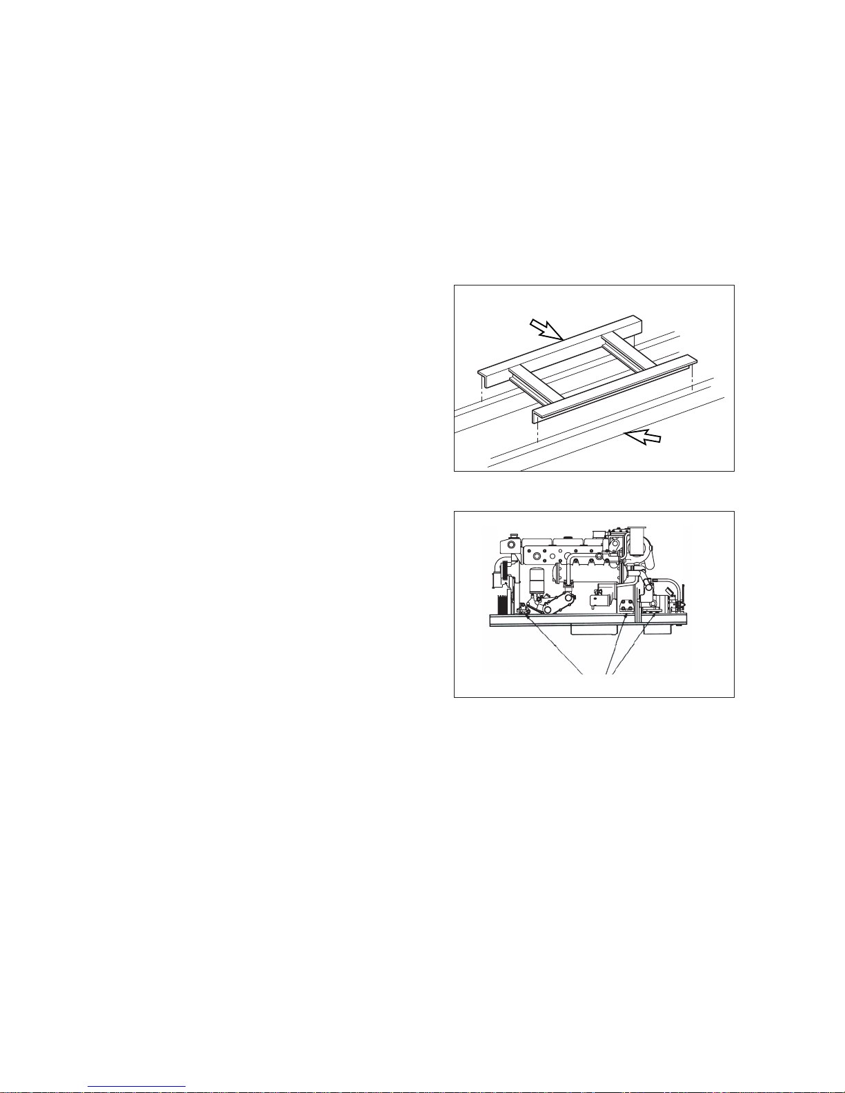
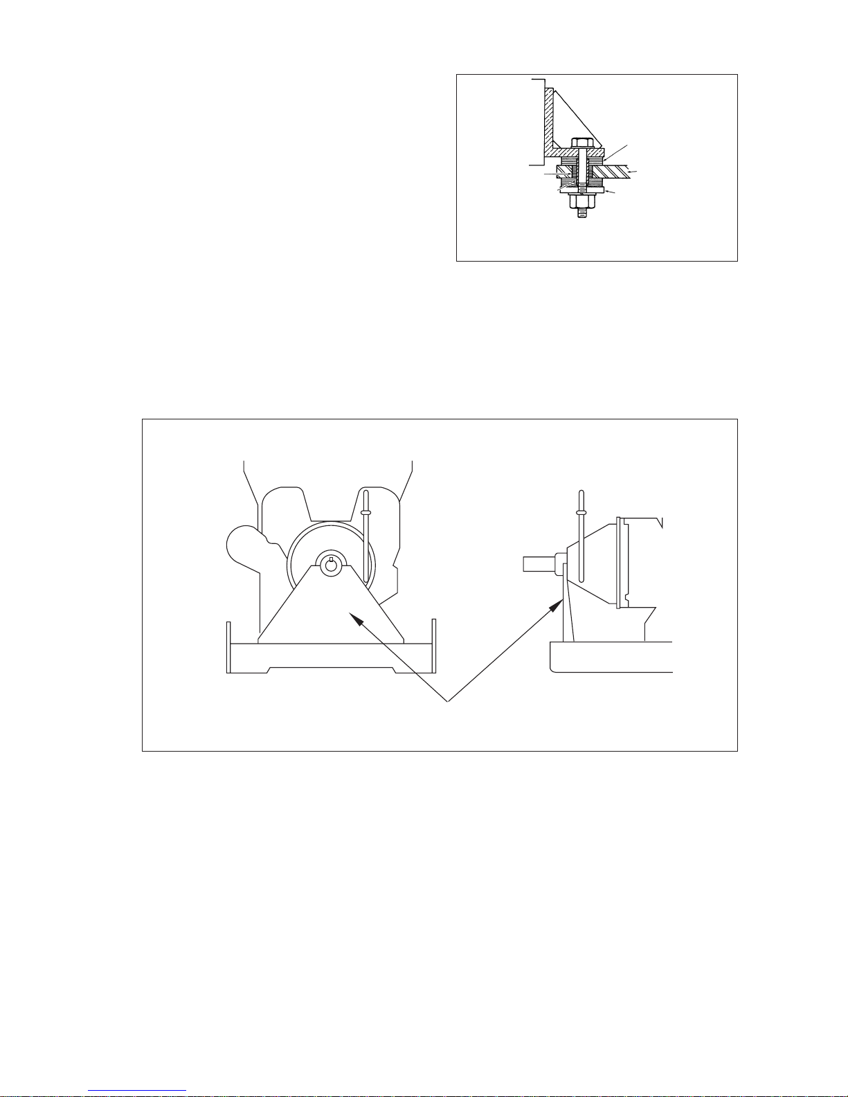
1.2. Engine Foundation
Requirements for the engine foundation are as following;
•
The foundation in the vessel should be able to take up propeller thrust in both directions
(ahead & astern) and transmit it on to the hull.
•
The weight of the drive system as well as all dynamic forces that occur in rough seas must
be safely taken up.
•
The torsion of the hull owing to rough seas and the load status must not be transferred to
the engine. The engine foundation is to be connected to the hull on an area as large as
possible
EB0O1001
Engine bed
Stringer
Engine mounting bracket
EB0O9007
•
Transverse cross bracing on the engine
bed and stringers should be used to
prevent lateral engine movement on solid
mounted systems.
•
In order to properly support the weight of
the engine and marine gear, a six-point
mounting system is recommended on all
DOOSAN marine engines.
When using a six-point mounting system,
the engine should be aligned using the
mounts at the front and at the marine gear
at first. Once the alignment is complete,
the next flywheel housing mounts should
be added.
- 3 -
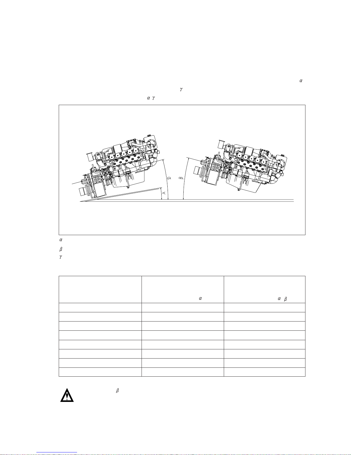
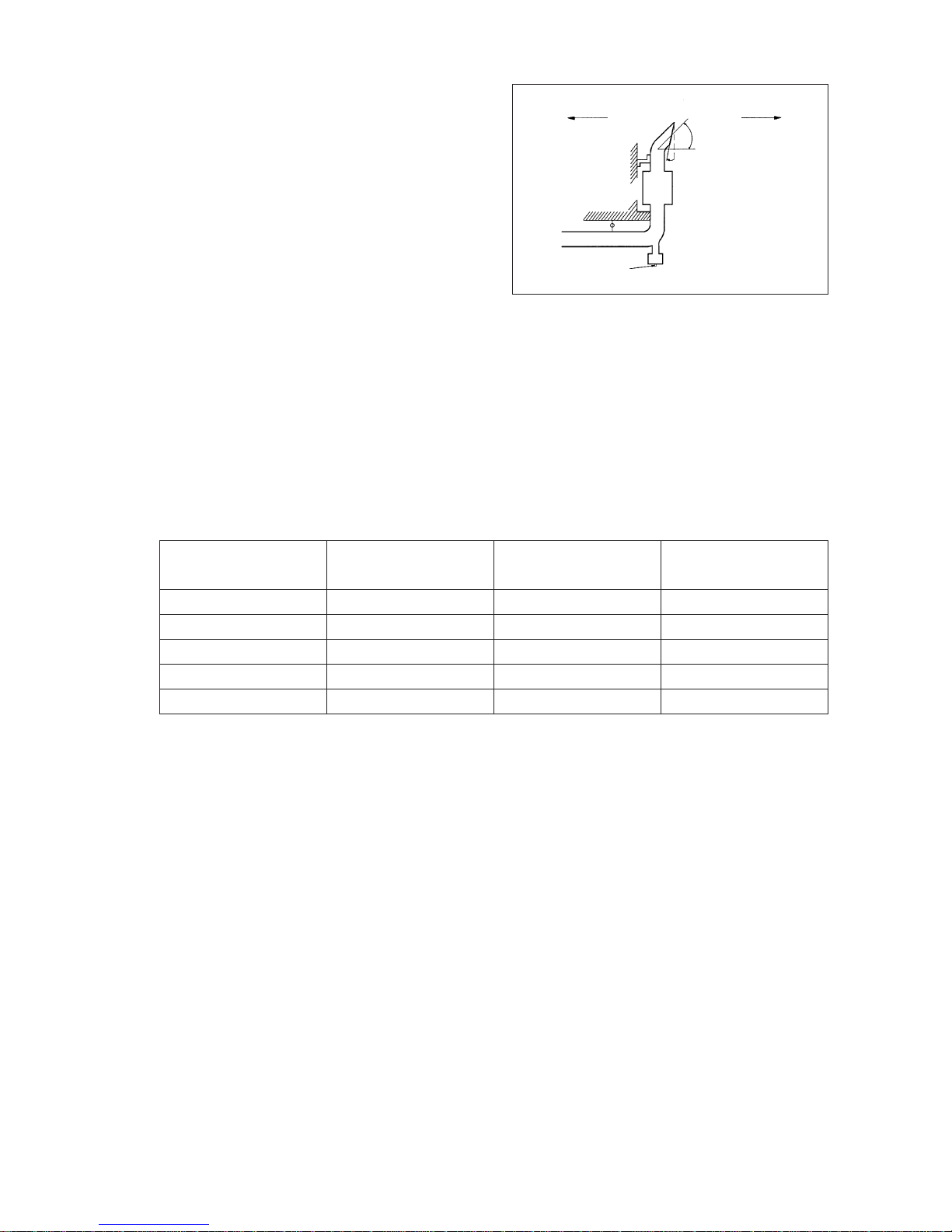
1.3. Max. Permissible Engine Inclination
The installation angle of the engine is an important factor in the construction of the sub-frame.
When the engine is to be installed in longitudinal direction, The maximum permissible inclination
must not be exceeded. The maximum permissible inclination is defined as the largest angle that
occurs in driving operation, ie, installation inclination plus the ship’s maximum trim angle.
The maximum installation angle of the engine is the maximum permissible inclination angle ( )
of the boat less the angle of the maximum trim( ) while the vessel is in motion. ie, the maximum
installation angle of the engine is( - ).
= max. permissible vessel inclination angle ; angle towards the flywheel end
= angle towards the non flywheel end
= trim of the vessel
<The maximum angles of inclination for the various engine are shown in below table>
Note : angle
The angle of 5˚toward the non-flywheel and must occur only while the vessel
is in motion.
- 4 -
Water line
EB0O1003
Max. oil pan permissible Max. angle of
Engine model angle of inclination engine installation
to the rear : ( ) inclination : ( - )
L034 / L034TI 20
˚
5
˚
L066TI 30
˚
5
˚
L136 / L136T 17
˚
5
˚
L136TI / L086TI 17
˚
5
˚
L196T / L196TI / L126TI 17
˚
5
˚
V158TI 17
˚
5
˚
V180TI 25
˚
5
˚
V222TI 25
˚
5
˚

If the installation angle of the engine is greater than that listed upper, the engine may occur
any engine damage. That is, connecting rods begin to dip into the oil in oil pan. So, this may
also cause high oil consumption, low power and the breather gas increasing and more
smokes. We recommend the engine installation angle to install below 6 degree for DOOSAN
marine engines.
1.4 Power Rating
Diesel engines are to be so designed that when running at rated speed their rated power can
be delivered as a continuous power. Continuous power means the net brake power which an
engine is capable of delivering continusously between the maintenance intervals stated by the
engine manufacturer.
To determine the power of all engines used on board ships with an unlimited range of service,
the following ambient conditions are to be used:
Engine driving generators are to be capable of developing 10% for a short period.(15minutes)
1.5 Inclinations
All components and systems shall be capable to operate in the following trim and pitch
positions.
1) Athwartships and for - and - aft inclinations may occur simultaneously.
2) Where the length of the ship exceeds 100m, the fore - and - aft static angle of inclination
may be taken as : (500)˚/L where L = length of ship(m).
3) In ships for the carrige of liquefied gases and of chemicals the emergency power supply
must also remain operable with the ship flooded to a final athwartships inclination up to
maximum 30˚.
- 5 -
Classification Barometric
Temperatures
Relative
societies pressure
Intake air
Seawater/
humidity
charge air coolant
DNV According to ISO3046/1
BV 1,000 mbar 45
˚C
32
˚C
60%
GL 1,000 mbar 45
˚C
32
˚C
60%
LR 1,000 mbar 45
˚C
32
˚C
60%
RINA Propuision 1,000 mbar 15
˚C
15
˚C
-
RINA Aux. service 1,000 mbar 45
˚C
30
˚C -
KR 1,000mbar 45
˚C
32
˚C
60%
Angle of inclination
1)
Installation ABS BV DNV GL LR RINA KR
Stat. Dyn. Stat. Dyn. Stat. Dyn. Stat. Dyn. Stat. Dyn. Sta. Dyn. Sta. Dyn.
Main and AUX athwartships
15 22.5 15 22.5 15 22.5 15 22.5 15 22.5 15 22.5 15 22.5
For - and - aft 5 7.5 5 7.5 5 7.5 5 7.5 52)7.5 5 7.5 5 7.5
Emergency athwartships
3)
22.5 22.5 22.5 22.5 22.5 22.5 22.5 22.5 22.5 22.5 22.5 22.5 22.5 22.5
For - and - aft 10 10 10 10 10 10 10 10 10 10 10 10 10 10
CHAPTER 2 ENGINE MOUNTING
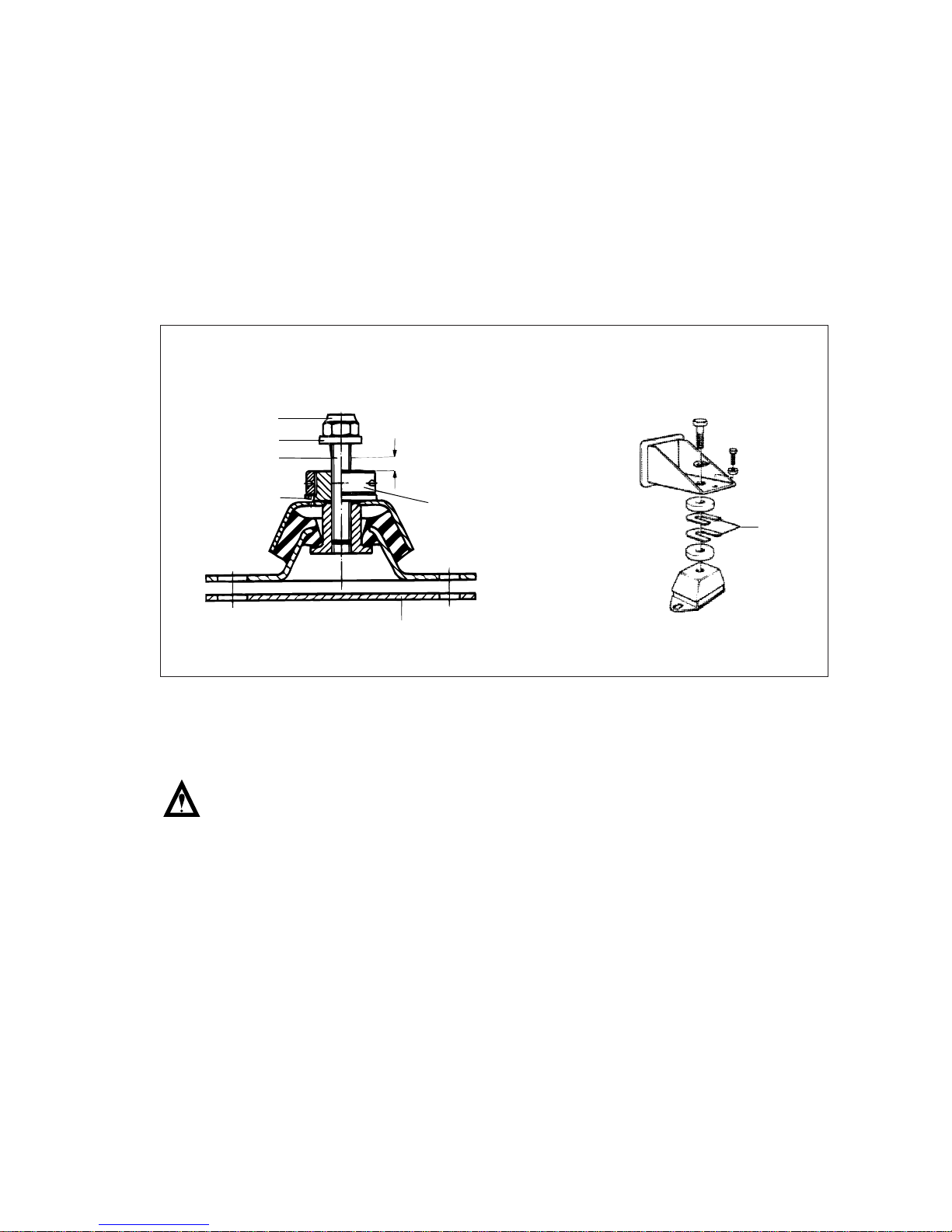
2.1. Flexible Mounting
Flexible mounting will generally be chosen for yachts and small boats because it reduces
vibration and noise levels.
Flexible engine mounts use the rubber isolators to absorb engine vibration before it is
transmitted to the hull. This will reduce noise and vibration in the boat. There are wide variety
of flexible mounts available on the market. Any mounts selected must hold the engine in
alignment and provide for acceptable mounting life. The isolator manufacturer should be
consulted for further recommendations.
The engine should be installed with sufficient clearance on all sides so that the allowable
engine movement will not cause structural or component damage.
Note : If the reduction gear must be mounted prior to installation in the hull, the
engine and reduction gear should be mounted on base rails and the whole
system installed together.
- 6 -
1
2
3
4
5
6
max. 10mm
EHO9001S
1. Mounting nut
2. Washer
3. Threaded pin
4. Clamp sleeve
5. Height adjustment
6. Shim
( manufactured as required)
Shims

2.2. Solid Mounting
The solid mounting engine is usually done by using brass or steel shims, pourable choking
compound and pads. The use of pourable choking compounds is the simplest and preferred
ways to solid mount the engine.
When using a choking compound, the alignment of the reduction gear and propeller shaft is
accomplished using jacking screws between the support brackets and the engine bed. The
mounting bolts can be loosely put into place at this point or a hole can be drilled through the
choking compound later. The jacking screws, mounting bolts and bottom of the engine bracket
should be coated with a grease or anti-bonding substance to allow them to be removed later.
Temporary dams are put on the engine bed and should extend approximately 13mm (0.5”)
above the bottom of the engine beds. The choking compound is poured in to fill the space
between the bracket and engine bed. Once the compound has solidified, the jacking screws
can be removed or left in place and the final mounting bolts are torqued down.
When using jacking screws on wood or fiberglass engine beds, steel plates should be used
under the jacking screws to prevent damage to the engine bed.
The choking compound manufacturer should be consulted for further recommendations.
- 7 -
EB0O2001
Engine
bracket
Chocking
compound
Temperary
dam
13mm(0.5")
Engine
bed
Jacking
screw
If a front power take-off clutch is used, it is a good practice to support the clutch. The clutch
available from DOOSAN marine Vee Series Models must be supported to avoid over stressing
the nose of the crankshaft due to the overhung weight.
- 8 -
EB0O2002
Fabreeka
washer
Steel tubing
approx. 0.8mm(1/32")
shorter than total
thickness of
fabreeka pads and
support bracker
13mm(1/2") fabreeka pad
Engine bad
4.8mm(3/16") steel plate
same length and
width as
fabreeka pads
Fabreeka type washers and pads consist of
layers of rubber impregnated canvas and
will provide a small amount of flexibility for
minor misalignment and a degree of
protection from shock loading. A steel plate
is required between the nut and Fabreeka
pad to protect the pad from wear and should
be the same size as the pad. It is still
necessary to use brass or steel shims to
align the engine and gear with the shafting.
Clutch support
EB0O2003
2.3. Arrangement of Engine and Reduction Gear
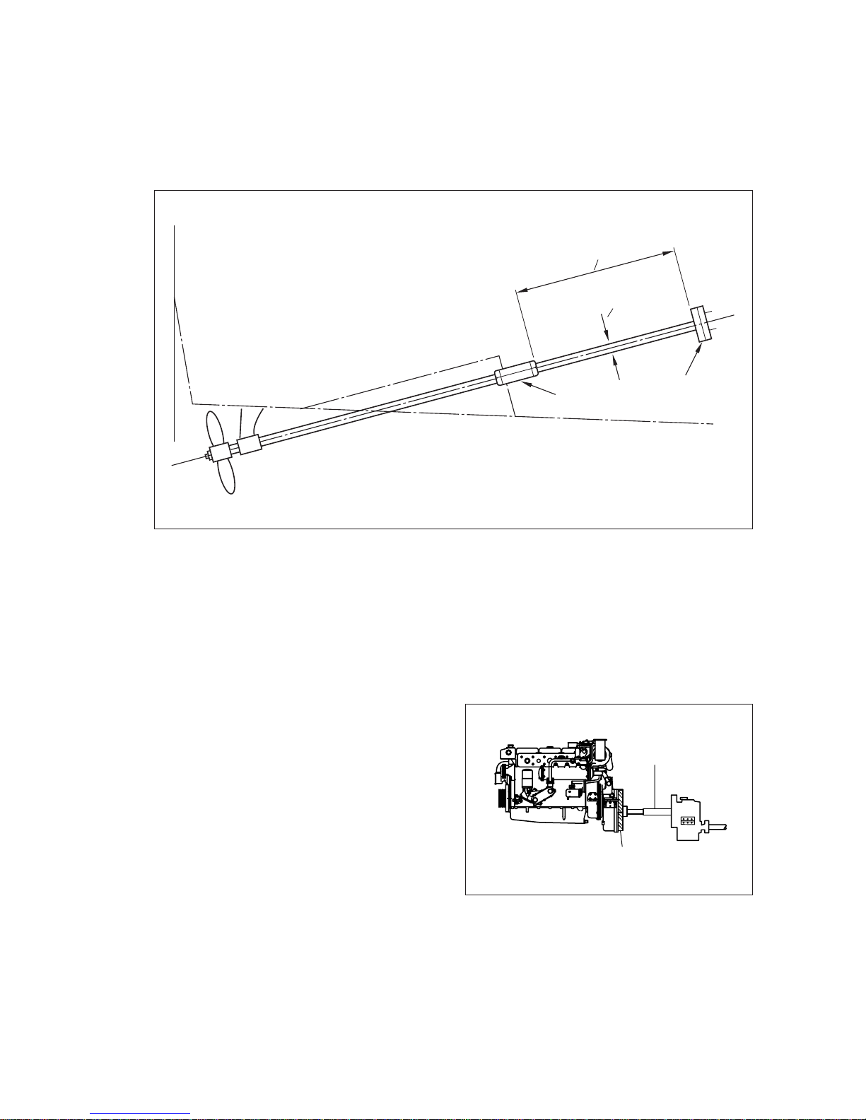
2.3.1. Engine and flanged-on reversing reduction gear
Engine and reduction gear can be constitute a unit. Propeller thrust is taken up by a
reduction gear thrust bearing.
In order to isolate engine vibration and prevent it from being transferred to the hull through the
propeller shaft, DOOSAN recommends that the distance from the reduction gear output flange
to a fixed stuffing box or first fixed bearing should be a minimum of 20 times the shaft
diameter. If the distance is less than this, a flexible coupling may be necessary to isolate the
engine vibration.
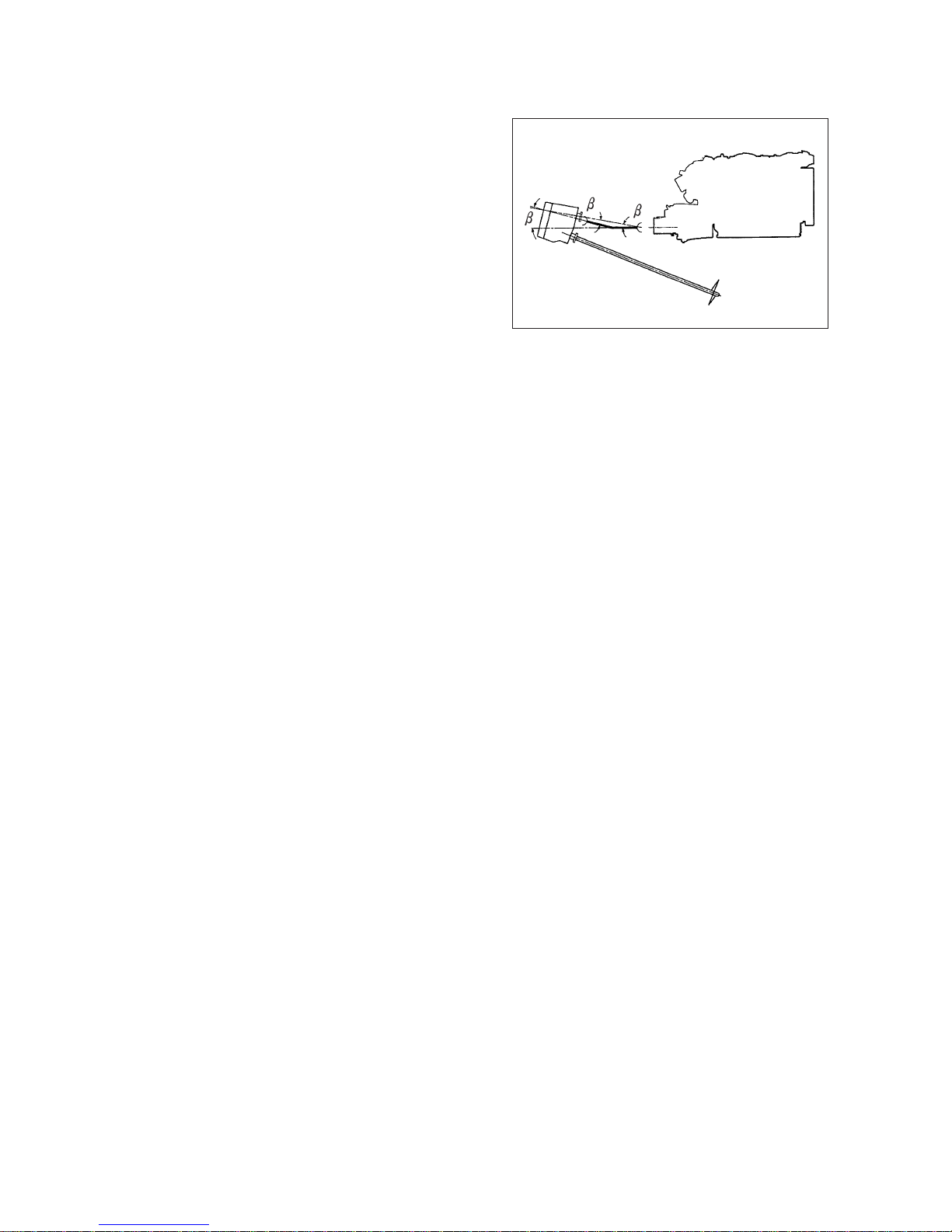
2.3.2. Engine and detached reduction gear
- 9 -
Stuffing box
Min. Shaft length
20 x o
Output flange
EB0O2004
o
Sliding shaft
Flexible coupling
EB0O9008
The reduction gear is installed separately
from the engine, taking up propeller thrust
via a thrust bearing. A constant velocity
joint, or a pair of universal joints, and
sliding shaft must be used to allow for the
relative motion between the flexible
mounted engine and the fixed reduction
gear.
2.3.3. V - type drive
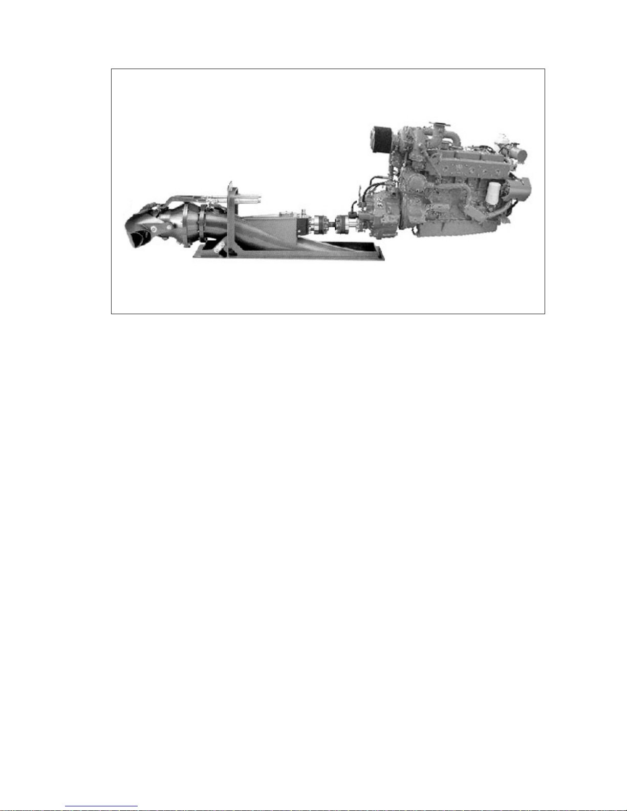
2.3.4. Jet type drive
More and more civilian and military boats, such as rescue boats, pilot boats, transport boats,
taxi boats, police boats and patrol boats, are using waterjets for propulsion. The waterjet
offers many benefits, which include giving the boat greater availability and maneuverability.
The waterjet also minimizes the draught of the boat and enables it to operate in shallow
water, as well as reducing the risk of personal injury during rescue and diving operations.
To obtain good economy from a waterjet installation, the jet unit and the engine should be
correctly matched to the full load service speed of the boat. The differences between a good
and a poor match are enormous with regard to fuel efficiency and overall performance of the
boat. A correctly sized and installed waterjet gives very small torque variations and creates
no engine overload, regardless of the boats loading conditions and speed. The jet is always
rotating in one direction, but the reversing of the boat is done by changing the jet stream
direction with a reverse deflector, which further reduces the load variations on the engine.
Waterjet has excellent characteristics when it comes to general maneuverability and comfort.
Superior control of the boat is achieved across the complete speed range, with small turning
radius and quick stops. The boat can rotate within its own length and with two jets the bot
can also move sideways. The lack of need of underwater rudder can make the vessel less
course stable, it is therefore important that the hull and the maneuvering control system is
correctly designed for the use of waterjets.
A waterjet installation has no underwater appendages which reduces the drag of the hull and
increases the overall efficiency in speeds above 20 - 30 knots depending on type of waterjets.
In comparison with conventional propeller system the inboard noise, vibration and the hydro-
acoustic noise is reduced as well.
Jet-type drives work according to the principle of jet propulsion. A jet of water is generated
whose thrust sets the vessel in motion.
- 10 -
EB0O2006
2
2
Engine and reduction gear is installed
separately and connected via an elastic
coupling and a universal joint. If universal
joints are to be used, it is important to
remember that it is necessary to have the
exact same angle at each joint under all
operating conditions in order for the
system to work properly.
The drive-line component manufacturer should always be consulted for more details on the
installation of their product.
2.3.5. The alignment of propeller
The alignment of the engine and marine transmission with the propeller shafting is essential
to minimize vibration, noise, power loss and stress in the driveline components.
While aligning the engine and gear, check both the propeller shaft flange bore and face. The
shaft and gear flanges should fit together without deflecting either the engine or the shaft
from its operating position. This will allow the propeller shaft flange and reduction gear output
flange to mate properly without over stressing the driveline components.
The shaft should then be rotated 180
˚
and checked again. The propeller shaft flange bore
and face alignment should not be done before the vessel is in the water and, on a solid
mounted engine, should be rechecked after the vessel has been in the water and loaded to
its normal operating condition.
Engine, gearbox and propeller shaft must be aligned in such a way that radial and angular
offset of all components remain within the pre-set tolerances.
(1) Radial offset check
The feeler of the dial indicator runs on the peripheral surface of the fixed flange. The
shaft end with the dial indicator placed on it must be turned. The reading must not vary
by more than 2 x 0.5 mm = 1.0 mm.
- 11 -
EB0O2009
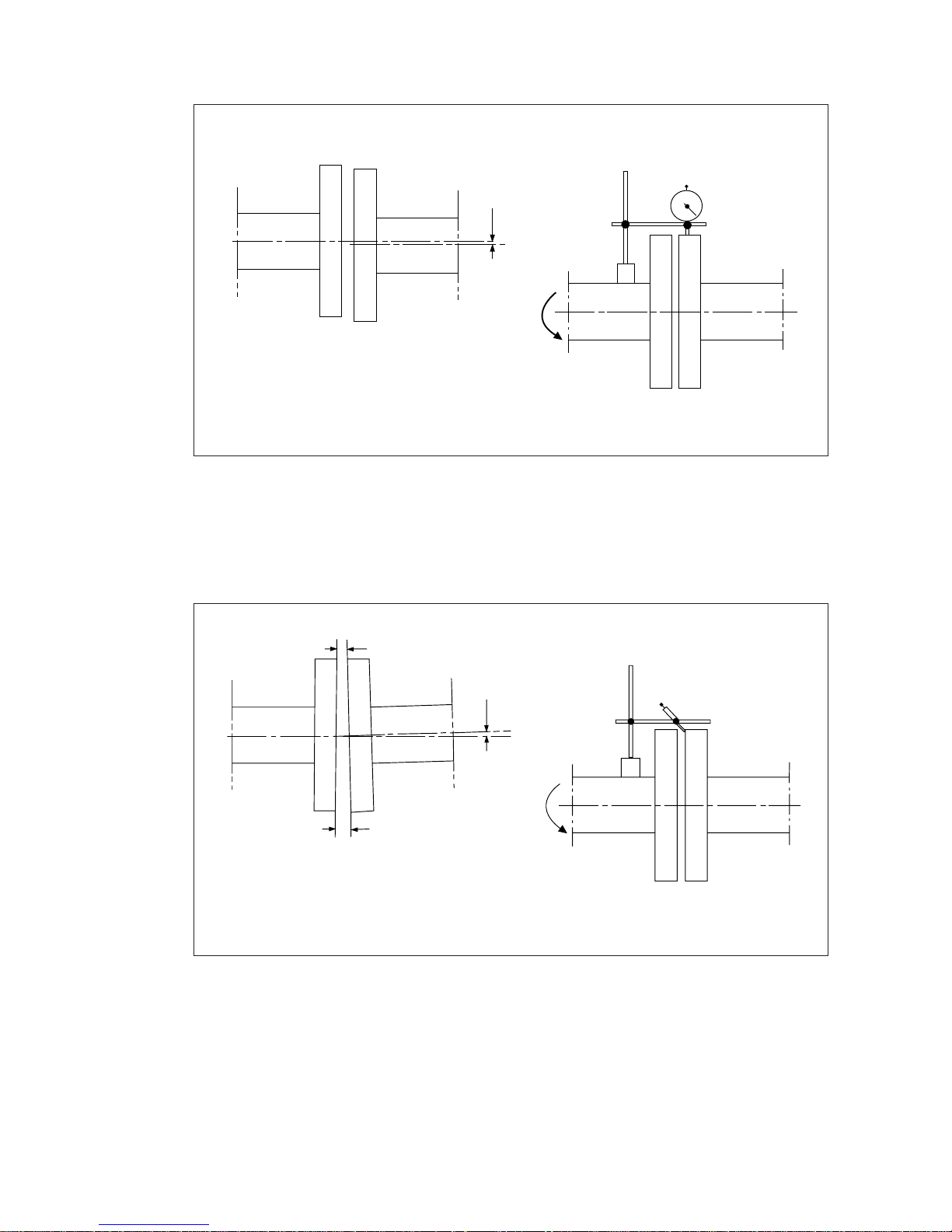
(2) Angular offset check
The feeler of the dial indicator runs on the front side of the fixed flange. The shaft end
with the dial indicator placed on it is to be turned.
The feeler must contact the mating surface. A 360
˚
turn is required for each check. The
max. Permissible angular offset must not be exceeded at any measuring point.
- 12 -
x
1
2
EB0O9009
1. Flange (e.g. gearbox output shaft)
2. Flange (e.g. propeller shaft)
1
2
X
3
X + max. 0.1mm
EB0O9010
1. Flange (e.g. gearbox output shaft)
2. Flange (e.g. propeller shaf)
Radial offset : x = max. 0.1 mm relative to a 200 mm flange diameter
or : x = max. 0.05 mm relative to a 100 mm flange diameter

CHAPTER 3 FRONT POWER-TAKE-OFF
3.1. Marine Installation Requirements
•
Belt-driven accessories must be mounted on the engine when a flexible mounting system is
used.
•
Brackets used to mount accessories must provide adequate strength to hold the static and
dynamic load of the accessory and avoid resonant vibration within the normal operating
range of the engine.
•
Variance in accessory loads must be considered when selecting accessory drive location
and capacity. Design service factors given in the installation recommendations should be
used when determining accessory loads.
•
Belt-driven equipment must be held in alignment to a tolerance of 1 mm in 200 mm (1/16
inch in 12 inches).
•
The total power taken off at the front of the crankshaft cannot exceed the maximum capacity
of the FPTO clutch and the total power absorbed from the engine may not exceed the
specified value of each model.
•
All exposed rotating components must have a protective guard.
3.2. Front Power Take-off Clutches
More power may be taken from a direct drive at the front of the crankshaft than any other
accessory drive location. Many DOOSAN marine engines can be fitted with FPTO clutch for
driving accessories such as a winch, fire pump, hydraulic pumps or generator.
All direct driven equipment will have some effect on torsional vibration. Excessive torsional
vibration in a system can result in excessive noise, gear failure, main bearing wear or, in the
most severe cases, crankshaft failures.
The total power taken off at the front of the crankshaft cannot exceed the capacity of the
FPTO clutch and the total required power from the engine may not exceed the values in the
list below.
This is the maximum amount of power that can be transmitted through the particular clutch.
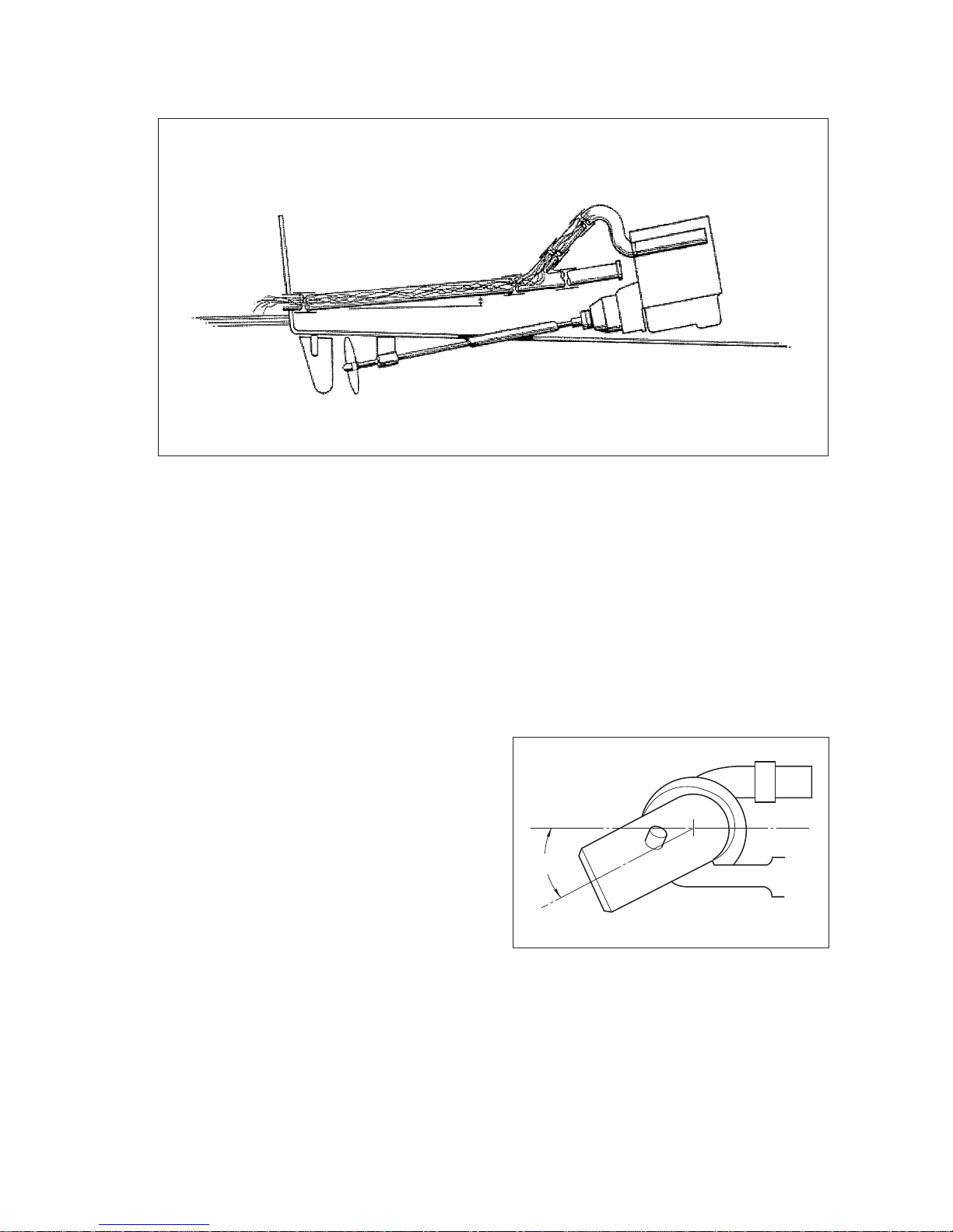
3.2.1. For maximum FPTO power
- 13 -
Engine
Crank pulley
Pillow blocks
Fiexible coupling
Driveshaft
V-pulley
EA4O7001
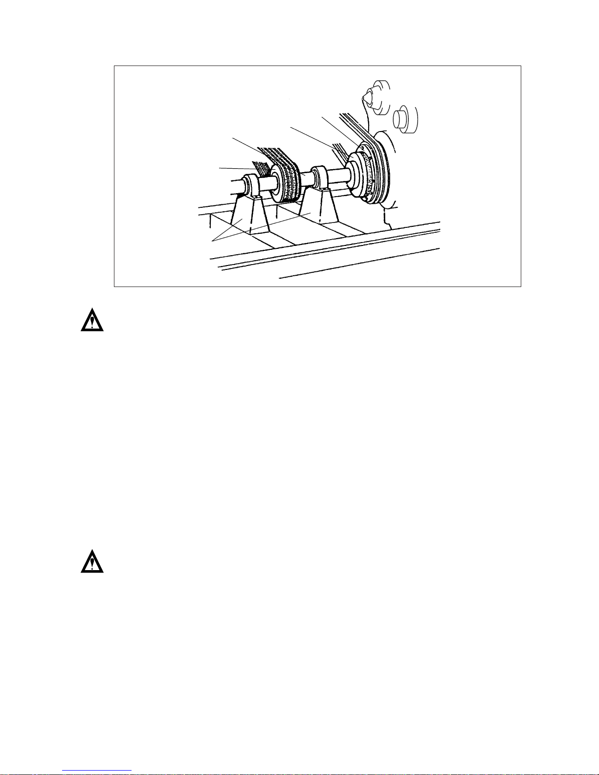
For front power take-off in engine, install a
flexible coupling to the engine front crank
shaft pulley and connect drive shaft and V-
pulley by supporting them with two pillow
blocks as shown in Fig. It is a standard
procedure to support driveshaft and V-
pulley with two pillow blocks by using
flexible coupling for connection to engine.
DOOSAN recommends you this type to
use front power take-off. (FPTO).

When the front PTO is installed, be sure to take deflection reading. Radial run-out should be
no more than 0.02 mm.
Be sure to limit the front PTO output within the maximum allowable horsepower as specified
for each model in figure below.
(Load represents when there is no propeller load)
Note : Upper listed loads represent allowable maximum torque.
3.2.2. For small cross drive power
- 14 -
Model Load(kW) rpm
L034 15 2,200
L034TI 31 2,600
L066TI 65 1,500
L136 60 1,800
L136T 72 1,400
L136TI 88 1,200
L086TI 120 1,600
Model Load(kW) rpm
MD196T 115 1,600
MD196TI 122 1,400
L126TI 132 1,600
V158TI 176 1,400
V180TI 220 1,600
V222TI 265 1,600
Engine
Crank
pulley
V-pulley, PTO
L
MAX. 170mm
(6.7 in) dia.
EA4O7002
(No supporting bearing on front side of
PTO pulley)
DOOSAN does not recommend this type
arrangement, which is not standard
procedure. However, If the FPTO as in
figure have to apply the drive arrangement,
the distance between the coupling end
face of engine pulley and the centerline
through pulley groove is not greater than
60 mm. The distance is indicated as “L” in
the figure.

<Driven loads by V-belt>
(L = Max. 60mm)
(Load represents when the propeller is running with engine)
Note : Upper listed loads represent allowable maximum torque.
3.3. Belt Drives
DOOSAN marine engines usually have belt drives for an alternator, sea water pump and at
least one or two free(grooves of) drive pulleys for other accessories. Many engines also have
crankshaft pulleys available for driving accessories. All of DOOSAN marine engine drives are
available with either A or B type V-belts that are designed to ISO 3046 standards.
If two power take-offs are at the same time, make sure that the resultant radial forces are as
small as possible.
The combination of companion flange and V-belt pulley can be used for such a multi power
take-off, as shown in below figure. It is advisable to shield V-belts and flanges properly, to
avoid accidents.
- 15 -
Model Load(kW) rpm
L034 12 2,200
L034TI 20 2,600
L066TI 38 1,800
L136 35 1,800
L136T 40 1,400
L136TI 50 1,200
L086TI 70 2,000
Model Load(kW) rpm
MD196T 68 1,600
MD196TI 74 1,400
L126TI 80 1,600
V158TI 95 1,400
V180TI 115 1,600
V222TI 125 1,600
Marine continuous rating
Engine speed (r.p.m)
Output (PS)
(g/PS
.
h)
500
170
160
150
400
300
200
100
1000 1500 2000 2500
1. Max. Power available
intermittant USE only
2. Propulsion curve
Fuel consumption
Max. FPTO
power
1
2
EB0O3001
Additionally, the total power(Load) required
by the propeller and FPTO cannot exceed
curve #1 on the power curve at any given
rpm. If the propeller is engaged, this
means that the max. power available at the
front is equal to the distance between
curves #1 and #2.
Note : New belts require a run-in period of 10 ~ 15 minutes under tension and should then
be retensioned. This allows for the initial stretch of the belt and will help prevent it
from jumping the pulley.
Brackets used to mount accessories must provide adequate strength to hold the
static and dynamic load of the accessory and avoid resonant vibration within the
normal operating range of the engine.
If a bracket has a natural frequency within the operating range of the engine, operation at that
speed will result in resonant vibration and failure of the bracket. So DOOSAN has no control
over the design or material of the component, they are not responsible for any damage
resulting from the failure of a non-DOOSAN supplied part.
When accessories are mounted on the engine, the mounting bracket should be attached to a
basic part of the engine such as the cylinder block or cylinder head whenever possible.
Accessories should not be mounted where they must be removed for normal engine
maintenance or where they are supported through a gasketed joint.
Note : Variance in accessory loads must be considered when selecting accessory drive
location and capacity. Design service factors given in the installation
recommendations should be used when determining accessory loads.
Since engine-driven accessories will have experience fluctuations in the load during normal
operation, the rated load of the accessories should be multiplied by a design service factor
when determining the load imposed on the engine by the accessory.
The direction as well as the load is important when considering belt driven accessories. The
load capacity of crankshaft pulleys and other drive locations will vary at different angles due to
the loading capability of the bearings.
- 16 -
Pillow blocks
V-pulley
Drive shaft
Crank pulley
Engine
EB0O3002
Flexible coupling
Note : Belt driven equipment must be
held in alignment to a tolerance of
1 mm in 200 mm (1/16 inch in 12
inches).
EB0O3003
A
B
C
EB0O3004
Crankshaft pulley
Accessory
1 mm in 200 mm
(1/16" in 12")
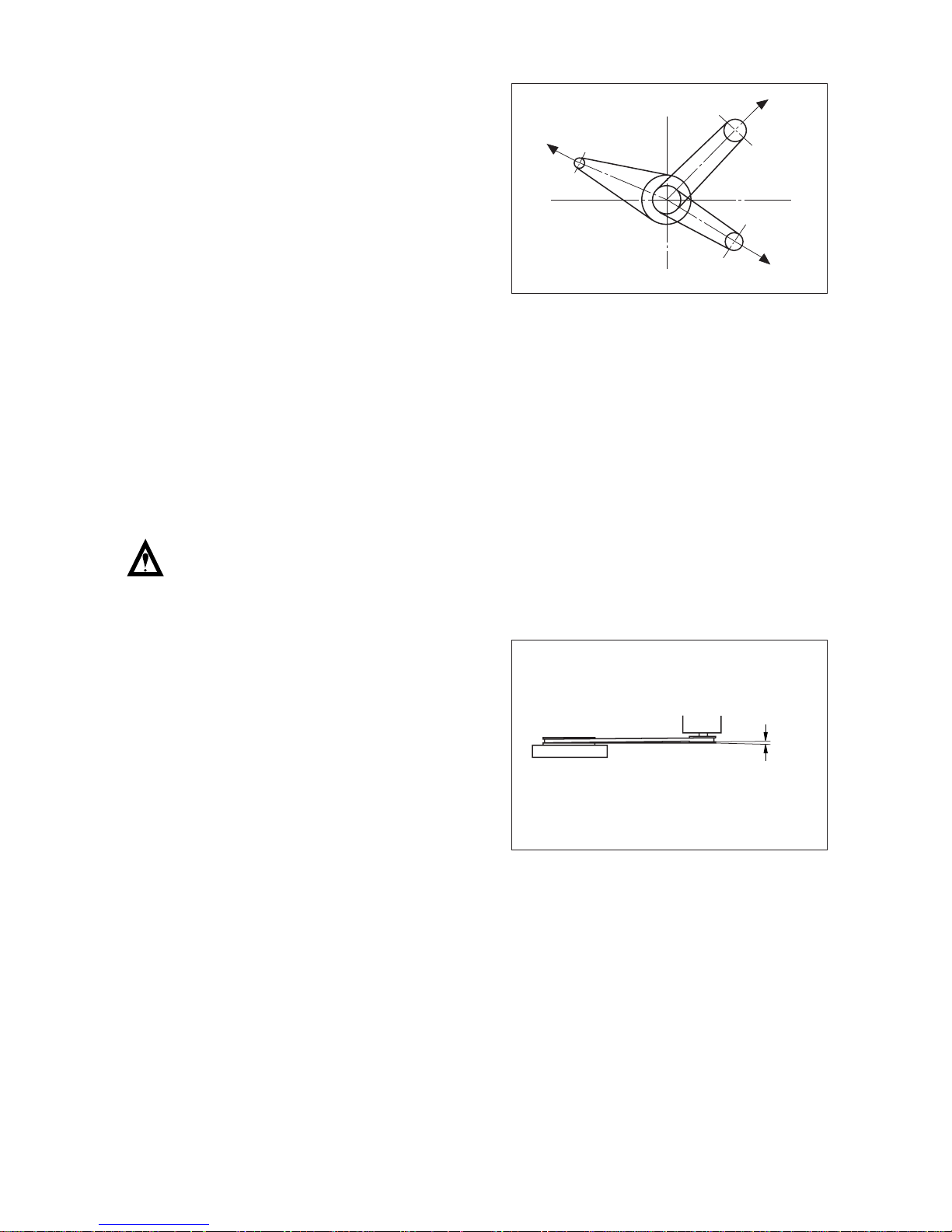
If two or more accessories are being
driven from a single multigroove pulley,
the accessories should be arranged to
have opposing belt pulls so that the
resulting force on the drive shaft is kept to
a minimum.
Additional pulley grooves or increasing
the belt size may exceed the safe loading
of the crankshaft or drive location.
Therefore the overloading should not be
allowed to prevent any malfunction.
Any device rigidly attached to the front of
the crank, other than an approved option,
must be analyzed for the effects on crank
bending, side-pull loading, mean and
vibratory torques, and the capability of
the crank bolted joint capacity.
Misalignment between the belt-driven
equipment and the engine will result in
bending forces on the shafts involved,
wearing of the belt, belt jumping and can
result in bearing or belt failure. This can
usually be checked with a straight edge.
- 17 -

CHAPTER 4 EXHAUST SYSTEM
The purpose of the exhaust system is to carry the exhaust gas from the engine to the
atmosphere with minimal flow restriction. Marine applications have two types of exhaust
systems, wet and dry.
4.1. Marine Installation Requirements
•
Thermal insulation or guards must be installed on dry exhaust systems.
•
Dry exhaust piping must not be installed near combustible material.
•
The exhaust system components must not impose excessive stresses on the exhaust
manifold or turbocharger due to weight, inertia, relative motion of the components or
dimensional change due to thermal growth.
•
The exhaust system must automatically prevent the entrance of water into the engine or
turbocharger whether it is from spray, rain, washing or any other source.
•
The exhaust gas must be dispersed so that it does not detrimentally affect the air cleaner
function, the engine ambient environment or the crew or passengers.
4.2. Dry Exhaust Systems (without sea water injection)
Depending on the temperature, the standard value for longitudinal expansion of steel pipes is
1 mm per meter and 100
˚
C.
It is not permissible to channel exhaust gases of several engines into one system. Multi-
engine systems are required to have a separate exhaust system for each and every engine to
prevent exhaust gases from penetrating from one running engine into another one.
For V-type engines it is recommended that the exhaust gases of both cylinder rows be
combined via an Y-pipe type.
Owing to high exhaust temperatures of several hundred degrees Celsius, exhaust pipes heat
up. For reasons of safety the pipes must be fitted with suitable anti-heat protection.
In order to prevent the engine room from heating up too much, a fireproof fuel and lubricating-
oil-repellent insulation is recommended.
To minimize exhaust gas back pressure, avoid sharp turns and manifolds.
- 18 -
R
d
EHO1202I
Design pipe bends with large radius only
(R/d
≥
1.5). If silencers are installed, ensure
that the max. permissible exhaust gas back
pressure is not exceeded.
Any bends in the exhaust system should be
made as smooth as possible. Sharp bends
can drastically increase the exhaust back
pressure.
Dry exhaust systems use steel or iron pipe for the exhaust piping, stainless steel flexible
sections, and steel for the mufflers. Due to the high exhaust temperatures and the thermal
conductivity of the metal components they can be very dangerous unless certain precautions
are taken.
One more flexible exhaust connection must under initial tension be installed between the
engine and the exhaust system.
A flexible exhaust connection must be installed in the exhaust piping within 1.2 m (4 feet) of
the engine exhaust outlet.
If the exhaust system has both long vertical and horizontal sections, separate flexible exhaust
sections must be used to absorb the thermal growth in each direction. The horizontal flexible
sections should be installed as far away from the vertical piping as possible to avoid collecting
soot and condensation in the bellows.
If water enters the turbocharger or engine it will damage the turbocharger and, if it enters the
exhaust manifold, may cause a hydraulic lock and engine failure upon start-up.
Condensation water collects in the exhaust system and under any circumstances water (rain,
spray) must not penetrate into the exhaust system of the engine.
- 19 -
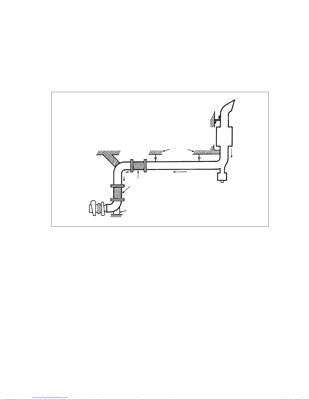
EB0O4001
Flexible
support
Flexible
support
Muffler
Solid
support
Flexible
connection
Arrow show the directions of thermal expansion.
Solid support
to engine
The actual exhaust piping size may vary depending upon the complexity of the routing and the
silencer used in the system.
The below table is showed the MINIMUM dry exhaust outlet pipe diameters for various engine
models and ratings when total exhaust piping length is below 5m. Add the diameter additional
5mm every 5m increasing. The actual exhaust piping size may vary depending upon the
complexity of the routing and the silencer used in the system.
4.3. Wet Exhaust System (with sea water injection)
In a wet exhaust, sea water is sprayed into the exhaust pipe. Heat is transferred from the
exhaust gases to the sea water and the exhaust gas temperature drops low enough.
A pipe bend (swan neck) is required in the exhaust pipe system followed by a downward
sloping exhaust pipe to prevent water from penetrating into the engine. The pipe bend must be
mounted immediately downstream of the engine. Following picture shows an example of a
swan neck for sea water injection into the exhaust pipe.
The diameter of the exhaust pipe
behind the sea water inlet must be 25% larger than that of the pipe bend.
Any bends in
the exhaust system should be made as smooth as possible. Sharp bends can greatly increase
the back pressure and should be avoided.
- 20 -
EB0O4002
Bow
45
o
Stern
Drain
Condensation trap
For this reason the water collector with a
drainage device must be installed near the
engine if long exhaust pipes are laid at an
ascending angle.
This can usually be accomplished in a dry
exhaust system by using a 45 degrees or
greater bend at the top of the piping. The
pipe should also have a slight overhang to
make the entrance of water more difficult.
The exhaust outlet should face the stern of
the boat so that any water that comes over
the bow will not enter the exhaust system.
Engine model
Minimum dry exhaust
Engine model
Minimum dry exhaust
inner diameter(mm) inner diameter(mm)
L034 76 MD196T / TI 115
L034TI 76 L126TI 115
L066TI 76 V158TI 145
L136 / T / TI 76 V180TI 145
L086TI 115 V222TI 145
<Schematic diagram for sea water injection>
Wet exhaust system
(Engine should be mounted above water line)
1. The water cooling exhaust elbow : sea water cools elbow, then discharges through
peripheral slot at discharge end of elbow into exhaust pipe.
2. The rubber exhaust hose flexible connection : must be oil and heat resistant.
3. Backwater surge chamber : prevents sea water surging into engine exhaust when vessel at
rest with stern exposed to oncoming waves.
4. Exhaust pipe : should have slight downward gradient toward discharge end.
5. End cover plate : available for inspection and cleanup purposes
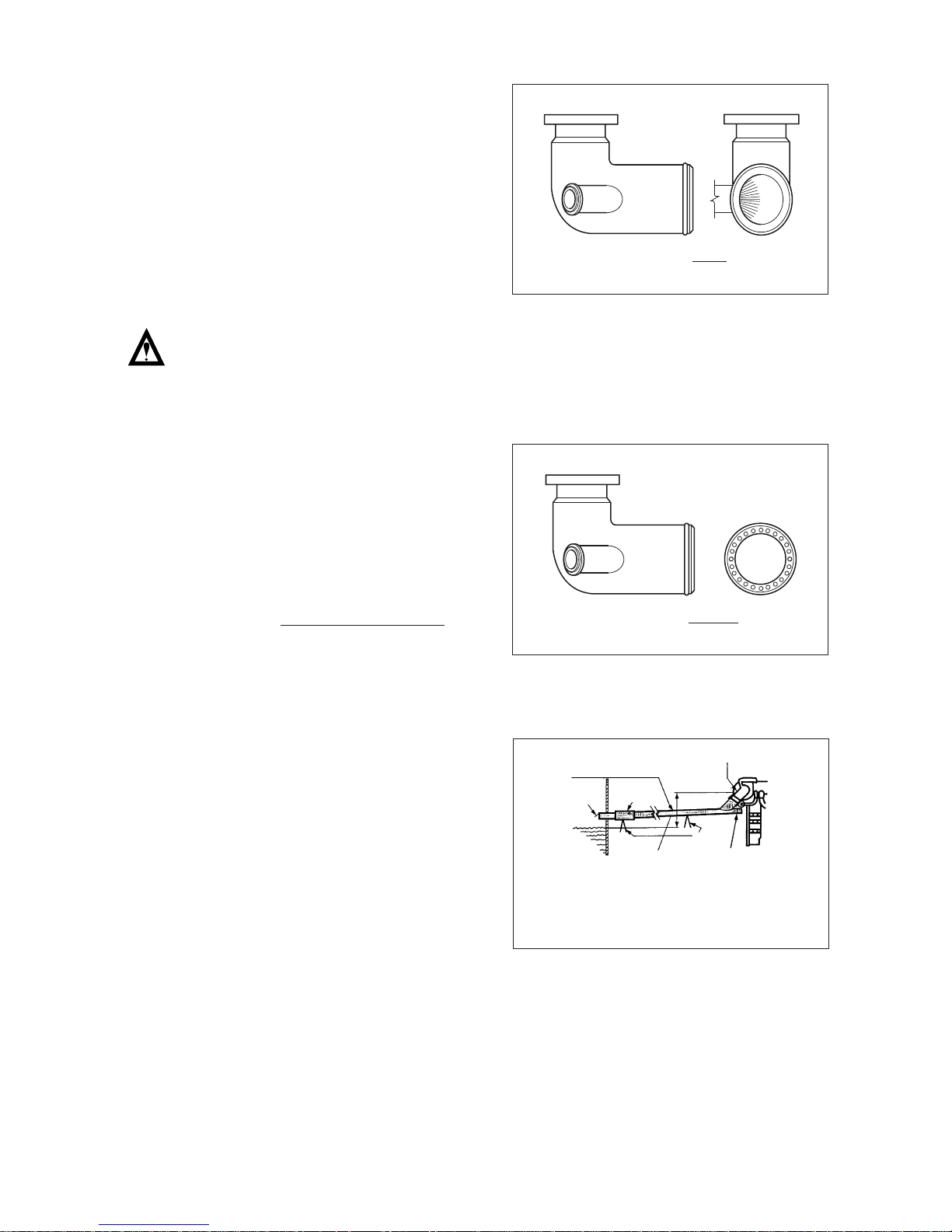
4.3.1. Design of water injection
In a wet exhaust system, sea water is
sprayed into the exhaust pipe at some
point downstream of the turbocharger.
If a water injection elbow is used, the
elbow should be directed downward at a
minimum of 15 degrees to prevent the
water being injected from getting back
into the turbocharger and should have a
pipe tap (1/8”) for exhaust restriction
measurements. Heat is transferred from
the exhaust gases to the sea water and
the exhaust gas temperature drops low
enough to allow the use of hard rubber
hose, fiberglass tube or other corrosion
resistant materials downstream of the
water injection.
- 21 -
EB0O4003
1
2
2
2
2
2
3
4
5
Slope(2 )
o
Exhaust discharge piping must have
adequate slope to avoid water entering
engine.
15O MIN
EB0O4006
Note : The surface temperature of the
exhaust piping should not exceed
93
˚
C (200˚F) under any operating
conditions.
DOOSAN recommends using evenly
distributed holes with an 8 mm (0.31 in)
diameter with the number of holes being
dependent upon the sea water flow. The
following equation can be used to
determine the number of holes:
No. of holes =
Lit./min(sea water flow)
10
4.3.2. Location of water injection
- 22 -
EB0O4004
BAD
Wherever water is injected in the exhaust
system, it is important that an even spray
pattern is achieved. If the spray pattern is
uneven, parts of the exhaust piping may
not be sufficiently cooled. This can result in
failure of the exhaust piping system due to
overheating and a possible safety hazard
from high surface temperatures.
EB0O4005
GOOD
If the engine is installed at a deep position
and the exhaust gas outlet at the system is
located just above or even below the water
line, a pipe bend (swan neck) must be
integrated into the pipe. This prevents
water from flowing into the engine when
the ship reverses or the water is rough.
Therefore, all exhaust outlets should be
located above the loaded water line.
A flapper valve may also be installed at the
exhaust outlet to help prevent water from
entering the exhaust system while the boat
is at rest.
EB0O4007
Supports
1. Water jacket exhaust elbow
2. Surge pipe
3. Exhaust piping
4. Water muffler
5. Flapper valve
6. Supporters
Waterline
12"(300mm)Minimum
1
2
3
4
5
6
2 Downward slope
o
 Loading...