


Machine Tools
NC Boring Maintenance
Manual (Alarm)
(DBC 130/F30i Series)

DBC 130(F30i Series) DBC130ALE2A
Table of Contents
1. Emergency Alarm........................................................................................... |
4 |
||
1.1 |
2001 |
Emg. Button or Axes Emergency.................................................................................... |
4 |
1.2 |
2002 |
Spindle Alarm is Detected .............................................................................................. |
6 |
1.3 |
2003 |
Power Circuit Overcurrent Detected............................................................................... |
7 |
1.4 |
2004 |
Hyd. Pump Motor Overload ............................................................................................ |
9 |
1.5 |
2005 |
Hyd. Pressure Down Alarm .......................................................................................... |
12 |
1.6 |
2006 |
Spindle Gear Shift Check Switch Alarm ....................................................................... |
14 |
1.7 |
2008 |
PSM Contact Check Error ............................................................................................ |
19 |
2. Cycle Alarm................................................................................................. |
21 |
||
2.1 |
2031 |
Return to Ref. Point in Manual ..................................................................................... |
21 |
2.2 |
2032 |
Feed Hold Push Button is Pressed............................................................................... |
24 |
2.3 |
2033 |
Air Pressure down Alarm .............................................................................................. |
26 |
2.4 |
2034 |
Coolant & Lub. Pump Overload.................................................................................... |
28 |
2.5 |
2035 |
Addition Coolant Unit Alarm.......................................................................................... |
30 |
2.6 |
2037 |
Power Back Up Module Power Failure......................................................................... |
32 |
2.7 |
2049 |
Spindle Speed Arrival Signal Error ............................................................................... |
34 |
2.8 |
2051 |
Spindle Orientation Overtime ....................................................................................... |
40 |
2.9 |
2052 |
Spindle Maximum rpm Setting Error............................................................................. |
44 |
2.10 |
2054 |
Illegal Condition in Spindle Rotation........................................................................... |
45 |
2.11 |
2056 |
Gear Shift Overtime Alarm.......................................................................................... |
47 |
2.12 |
2057 |
Spindle Tool Clamp/Unclamp Change Alarm ............................................................. |
51 |
2.13 |
2058 |
Tool No. Select Keep Relay Not Set........................................................................... |
53 |
2.14 |
2059 |
T-Code Command Initial Condition............................................................................. |
57 |
2.16 |
2061 |
T-Code Over Command Error .................................................................................... |
65 |
2.17 |
2062 |
M06 Command Overtime Alarm ................................................................................. |
66 |
2.18 |
2080 |
Spindle Head Oil Overflow Alarm ............................................................................... |
74 |
2.19 |
2081 |
Y-Axis Clamp/Unclamp Alarm..................................................................................... |
76 |
2.20 |
2082 |
Spindle Stop in Cutting Alarm..................................................................................... |
78 |
2.21 |
2083 |
ATC Guide Rail Locate Sensor Error.......................................................................... |
79 |
2.22 |
2085 |
W-Axis Clamp/Unclamp Alarm ................................................................................... |
81 |
2.23 |
2133 |
Guide Rail Locating State Alarm................................................................................. |
83 |
2.24 |
2139 |
Spindle Run Signal Alarm........................................................................................... |
86 |
3. Single Block Alarm....................................................................................... |
87 |
3.1 2160 Lubrication Oil Level Low X .......................................................................................... |
87 |
1

|
DBC 130(F30i Series) |
DBC130ALE2A |
||
|
|
|
|
|
3.2 |
2161 |
Lubrication Oil Pressure Down..................................................................................... |
89 |
|
3.3 |
2162 |
|
Parts Count End Alarm ................................................................................................. |
91 |
3.4 |
2164 |
|
Oil Cooling Unit Alarm .................................................................................................. |
92 |
3.5 |
2165 |
|
Oil Cooling Flow Alarm ............................................................................................... |
102 |
3.6 |
2166 |
Filter Changer of TSC. Alarm ..................................................................................... |
104 |
|
3.7 |
2168 |
|
Coolant Pressure Down Alarm ................................................................................... |
105 |
3.8 |
2170 |
Tool Life Count End Alarm.......................................................................................... |
106 |
|
3.9 |
2171 |
RST Command Alarm On STL ................................................................................... |
107 |
|
3.10 |
2183 |
Table Lubrication Oil Flow Alarm .............................................................................. |
108 |
|
3.11 |
2185 Lubrication Oil Level Low Y, Z ................................................................................... |
110 |
||
3.12 |
2186 |
Lubrication Oil Pressure Down.................................................................................. |
111 |
|
4. Massage Alarm........................................................................................... |
113 |
|||
4.1 |
2193 |
|
Safety Switch Unlocked............................................................................................... |
113 |
4.2 |
2195 |
OPDoor Close, Must Be D-Open .............................................................................. |
115 |
|
4.3 |
2196 |
|
Coil Conveyor Overload Alarm .................................................................................... |
117 |
4.4 |
2197 |
|
Chip Conveyor Alarm................................................................................................... |
119 |
4.5 |
2198 |
Auto Power Off Ready................................................................................................ |
121 |
|
4.6 |
2200 |
Warming Up Not Complete......................................................................................... |
123 |
|
4.7 |
2202 |
|
Machine Lock ............................................................................................................. |
125 |
4.9 |
2205 |
Measurement Device Battery Low ............................................................................. |
130 |
|
4.10 |
2206 |
Measurement Device Alarm ..................................................................................... |
131 |
|
4.11 |
2207 Machine Interference Zone Error.............................................................................. |
132 |
||
4.12 |
2208 |
Machine In Service Mode......................................................................................... |
137 |
|
4.13 |
2215 |
Tool Length Sensor Up/Down Alarm ........................................................................ |
138 |
|
4.14 |
2216 |
Must Be Return to Ref. Point X ................................................................................ |
140 |
|
4.15 |
2217 |
Must Be Return to Ref. Point Y ................................................................................ |
141 |
|
4.16 |
2218 |
Must Be Return to Ref. Point Z ................................................................................ |
142 |
|
4.17 |
2219 |
Must Be Return to Ref. Point W ............................................................................... |
143 |
|
4.18 |
2220 |
Must Be Return to Ref. Point B ................................................................................ |
144 |
|
4.19 |
2221 |
Must Be Return to Ref. Point 6................................................................................. |
145 |
|
4.20 |
2223 |
Table (B-Axis) Locate/Unlocate ................................................................................ |
146 |
|
4.21 |
2228 |
Operator Door Open Alarm....................................................................................... |
150 |
|
4.22 |
2234 |
Spindle Gear Detection Switch................................................................................. |
152 |
|
4.23 |
2241 |
Wait. Pot or Spindle Tool data Zero.......................................................................... |
156 |
|
4.24 |
2250 |
Manual Mode Selected On ATC Panel..................................................................... |
158 |
|
4.25 |
2254 |
ATC Carriage Overtime Alarm .................................................................................. |
160 |
|
4.26 |
2255 |
Changer Arm In/Out Alarm ....................................................................................... |
175 |
|
2

DBC 130(F30i Series) |
DBC130ALE2A |
|
|
4.27 |
2260 |
ATC Magazine Rotation Overtime ............................................................................ |
177 |
4.28 |
2261 |
ATC Magazine Door Unlocking ................................................................................ |
179 |
4.29 |
2262 |
ATC Magazine Guard Door Open ............................................................................ |
181 |
4.30 |
2263 |
ATC Magazine Servo Unit Alarm .............................................................................. |
183 |
4.31 |
2264 |
Tool Magazine Battery Alarm.................................................................................... |
184 |
4.32 |
2265 |
Tool Magazine Servo Unit Off Signal Error............................................................... |
186 |
4.33 |
2266 |
Servo Tool Magazine Number Mismatched.............................................................. |
188 |
4.34 |
2269 |
Tool Magazine Pot Detection Check Alarm .............................................................. |
190 |
4.35 |
2270 |
Tool Pull Out Switch Alarm ....................................................................................... |
192 |
4.36 |
2282 |
Carriage Servo Unit Alarm........................................................................................ |
194 |
4.37 |
2283 |
Carriage Battery Alarm ............................................................................................. |
195 |
4.38 |
2284 |
Carriage Servo Unit Off Signal Error ........................................................................ |
197 |
4.39 |
2323 |
B-Axis (Table) Clamp/Unclamp Alarm ...................................................................... |
200 |
4.40 |
2341 |
ATC APC Interlock Alarm.......................................................................................... |
203 |
4.41 |
2389 |
Angular Mismatch Alarm (M121 Must Be Released)................................................ |
208 |
4.42 |
2392 |
Facing Head Interlock............................................................................................... |
210 |
3

DBC 130(F30i Series) |
DBC130ALE2A |
|
|
1.Emergency Alarm
1.12001 Emg. Button or Axes Emergency
1)Description
The Emergency Stop push-button switch on the operation panel is pressed down, or at least one Emergency Stop limit switch for the axes is tripped.
2)Cause of problem
The Emergency Stop push-button switch on any of the main OP, the tool magazine OP, or the chip conveyor is pressed down.
The Limit switch for an emergency stop located for each axis (X, Y, Z, W) is pressed down.
An error in the Emergency Stop switch on the OP, or the Emergency Stop limit switch for each axis, or other related parts
Disconnection of the wiring
3)Action
Check if the red mushroom push-button switch on the main OP, the tool magazine OP, or the chip conveyor is pressed down, and if so, turn the switch counter clockwise to release it.
If the Limit switch for any axis (X, Y, Z, or W) is tripped, press both the Machine Ready
switch and the Emergency Release switch simultaneously to enter the Machine Ready state. (If you want to return to the emergency stop state, simply release the switch.) Then, move the problem-making axis in jog or handle mode so as to remove it from the emergency stop limit switch.
Check the Emergency Stop push-button switch on the main OP, the Emergency Stop limit switch on the axis, and other related parts for any problem. Repair or replace the defective
part if necessary.
Disconnection of the wiring
Refer to the circuit diagram and use the electric tester to check each terminal block. If you find an error, repair or replace the defective part.
Part Name |
|
Part No. |
|
|
Symbol |
Spec. |
|
Maker |
|||
|
|
|
|
||||||||
|
|
|
|
|
|
|
|
|
|
|
|
Switch, Emergency P/B |
ESWPB0439 |
|
|
SB1,7,9,61 |
B30-81L2B |
|
KACON |
||||
|
|
|
|
|
|
|
|
|
|
|
|
Switch, Limit |
|
ESWLM0111 |
|
SL11.1,12.1,13.1,15.1 |
D4C-4332 |
|
OMRON |
||||
|
|
|
|
|
|
|
|
|
|
|
|
|
|
|
|
|
|
|
|
|
|||
Signal |
Address |
Device |
|
I/O |
|
Connector |
|
Numbering |
|||
|
|
|
Symbol |
|
|
|
(Pin) |
|
|
|
|
Emergency Stop |
X8.4 |
-SB1,7,9,10 |
I/O Module Slot 7 |
|
XJ413 (23) |
|
|
ESP |
|||
ESP.M |
|
|
|
||||||||
|
|
|
|
|
|
|
|
|
|
||
4
DBC 130(F30i Series) |
DBC130ALE2A |
|
|
|
|
|
|
|
|
|
|
|
|
|
|
Emergency Button or
Axes Emergency
Adress |
Symbol |
Coil Comment |
|
X8.4 |
ESP.M |
Emergency Stop |
|
|
|
|
|
A0.0 |
2001 |
Emg. Button or Axes Emergency |
|
|
|
|
|
X32.4 |
MRD.M |
Machine Ready |
|
|
|
|
|
R652.7 |
ARST |
Alarm Reset |
|
|
|
|
5

DBC 130(F30i Series) |
DBC130ALE2A |
|
|
1.22002 Spindle Alarm is Detected
1)Description
There occurred an alarm from the main spindle drive unit.
2)Cause of problem
An error found in the main spindle drive unit
An error found in the spindle motor, power cable or signal cables
3)Action
Check the alarm number that is displayed on the main spindle drive unit of the electric cabinet. Take a necessary measure according to the alarm number.
Refer to "Troubleshooting by the spindle amplifier alarm" in the appendix.
Check the spindle motor for the 3-phase power source and the feedback cable if there is a problem.
Main Spindle Servo
Alarm
Address |
Symbol |
Coil Comment |
|
F45.0 |
ALMA |
Spindle Alarm |
|
|
|
|
|
R820.1 |
2002 |
Spindle Alarm is Detected |
|
|
|
|
|
R652.7 |
ARST |
Alarm Reset |
|
|
|
|
Alarm Display
6

DBC 130(F30i Series) |
DBC130ALE2A |
|
|
1.32003 Power Circuit Overcurrent Detected
1)Description
The circuit protector that is installed in the electric cabinet is tripped.
2)Cause of problem
The circuit protector is triggered. (Abnormal signal is detected)An error in power control
The circuit protector has an error itself.
3)Action
Find out the cause that the circuit protector is tripped.
(ex) If QF22 is tripped, check the secondary circuit (L+) of QF22 if it's short-circuited, and take a necessary measure before turning the circuit protector back on.
If the alarm occurs but no circuit protector is tripped, measure the resistance of each contact point, and find out the defective circuit protector, and replace it with a new one.
If you measure the resistance on the contact point of the circuit protector that is turned on, you will get "0" ohm if it's normal.
If you have found nothing wrong in steps and above, that is thought to be caused by the I/O circuit board. Check the I/O board and repair or replace it if necessary.
Part Name |
|
Part No. |
|
|
Symbol |
|
|
|
Spec. |
Maker |
|
|
|
|
|
|
|
||||||
Breaker, Auxiliary |
|
ENFBX0290K |
QF22,23,25,28,91 |
|
C60,26924,of Contact |
Schneider |
|||||
|
|
|
|
|
|
|
|
|
|
|
|
Protector, Circuit |
|
ENFBX0268K |
QF22, 28 |
|
|
C60. 24430. 6A. 1P |
Schneider |
||||
|
|
|
|
|
|
|
|
|
|
|
|
Protector, Circuit |
|
ENFBX0272K |
|
QF23 |
|
|
C60. 24433. 13A. 1P |
Schneider |
|||
|
|
|
|
|
|
|
|
|
|
|
|
Protector, Circuit |
|
ENFBX0551K |
|
QF28 |
|
|
C60. 24436. 25A. 1P |
Schneider |
|||
|
|
|
|
|
|
|
|
|
|
|
|
Protector, Circuit |
|
ENFBX0266K |
|
QF91 |
|
|
C60. 24427. 3A. 1P |
Schneider |
|||
|
|
|
|
|
|
|
|
|
|
|
|
|
|
|
|
|
|
|
|
|
|||
Signal |
Address |
Device |
|
|
I/O |
|
Connector |
Numbering |
|||
|
|
|
Symbol |
|
|
|
|
(Pin) |
|
||
Circuit Protector Trip |
X2.3 |
-XT412 |
|
Input Module : Slot |
XJ412 (15) |
M214 |
|||||
TRIP.M |
|
|
06 |
|
|||||||
|
|
|
|
|
|
|
|
|
|||
Power Circuit Overcurrent
Detected
7

|
DBC 130(F30i Series) |
|
|
DBC130ALE2A |
||||
|
|
|
|
|
|
|
|
|
|
|
|
|
|
|
|
|
|
|
Address |
|
Symbol |
|
Coil Comment |
|||
|
|
|
|
|
|
|
|
|
|
X2.3 |
|
TRIP.M |
|
Circuit Protector Trip Detection |
|||
|
|
|
|
|
|
|
|
|
|
R652.7 |
|
ARST |
|
Alarm Reset |
|||
|
|
|
|
|
|
|
|
|
|
A0.2 |
2003 |
|
Circuit Protector Trip |
||||
|
|
|
|
|
|
|
|
|
|
X2.3 |
|
TRIP.M |
|
Circuit Protector Trip Check |
|||
|
|
|
|
|
|
|
|
|
|
|
|
|
|
|
|
||
|
|
|
|
|
||||
|
|
|
|
Input Module (AID32E) : Slot 6 |
|
|||
|
|
|
|
|
X2.3 |
|||
|
|
C20C |
21,36 |
|
15 |
|
|
|
|
|
40,41 |
|
|
|
|||
|
|
XJ412 |
|
|
|
|
|
|
|
|
M |
|
|
|
A5 |
||
|
|
|
|
|
|
|||
|
|
|
XT412 |
|
|
|
|
|
M214
a1
-QF91 APC Motor Brake
a2
M214D
23
-QF25 Work Light
24
M214C
a1
-QF23 AC 110V Source
24
M214B
a1
-QF22 Servo Motor Brake
a2
M214A
a1
-QF28 Solenoid DC Power Source
1L+
a2
Circuit Protector Trip
8
DBC 130(F30i Series) |
DBC130ALE2A |
|
|
1.42004 Hyd. Pump Motor Overload
1)Description
Hyd. An excessive electric current is detected in the hydraulic pump motor or the lubricant pump motor of the spindle head.
2)Cause of problem
The hydraulic pump motor, the lubricant pump motor of the spindle head, or the power cable is burnt out.
The circuit breaker that detects the excessive current is overloaded or defective itself.
3)Action
Check the hydraulic pump motor, the lubricant pump motor of the spindle head, or the
power cable if there is a problem. Repair or replace the defective part if necessary.
Check the circuit breaker for the load settings and make correction if necessary. If the circuit breaker itself has an error, replace it with a new one.
(You can detect a defective circuit breaker by checking the resistance on either circuit of M212 or 1L+)
▪Overload settings
QM31 : 5.5 Kw : 24 A
QM33 : 3.7 Kw : 16.1 A
QM34 : 0.1 Kw : 0.7 A
QM73 : 1.5 Kw : 7 A
QM10 : 1.5 A
Part Name |
Part No. |
Symbol |
Spec. |
Maker |
|
Breaker, Auxiliary |
ENFBX0290M |
QM33,34,73 |
TESYS. GVAE20. 2A |
Schneider |
|
|
|
|
|
|
|
Breaker, Motor |
ENFBX0269M |
QM31 |
TESYS. GV3P32. 23-32A |
Schneider |
|
Circuit |
|||||
|
|
|
|
||
Breaker, Motor |
ENFBX0261M |
QM33 |
TESYS. GV2ME21. 17-23A |
Schneider |
|
Circuit |
|||||
|
|
|
|
||
Breaker, Motor |
ENFBX0254M |
QM34 |
TESYS. GV2ME05. 0.63-1A |
Schneider |
|
Circuit |
|||||
|
|
|
|
||
Breaker, Motor |
ENFBX0259M |
QM73 |
TESYS. GV2ME14. 6-10A |
Schneider |
|
Circuit |
|||||
|
|
|
|
Signal |
Address |
Device |
I/O |
Connector |
Numbering |
|
Symbol |
(Pin) |
|||||
Hydraulic Motor |
X2.1 |
-KA11 |
Input Module Slot 06 |
XJ412 (32) |
M212 |
|
Overload |
HOVL.M |
|||||
|
|
|
|
9

DBC 130(F30i Series) |
DBC130ALE2A |
|
|
Hyd. Pump Motor
Overload
|
Address |
|
|
Symbol |
|
|
|
|
Coil Comment |
|
|||||||
|
|
|
|
|
|
|
|
||||||||||
|
X2.1 |
|
|
HOVL.M |
|
Hydraulic Pump Motor Overload |
|
||||||||||
|
|
|
|
|
|
|
|
|
|
|
|
|
|
|
|
||
|
A0.3 |
|
|
2004 |
|
|
Hydraulic Pump Motor Overload |
|
|||||||||
|
|
|
|
|
|
|
|
|
|
|
|
|
|
|
|
|
|
|
R652.7 |
|
|
ARST |
|
Alarm Reset |
|
|
|
|
|
|
|
|
|||
|
|
|
|
|
|
|
|
|
|
|
|
|
|
|
|
|
|
|
|
|
|
|
|
|
|
|
|
|
|
|
|
|
|
|
|
|
|
|
|
|
|
|
|
1L+ |
|
|
|
|
|
|
|
|
|
|
Input Module (AID32E) : Slot 6 |
|
|
|
|
|
|
|
|
|
|
|
|
|
|||
|
|
|
|
|
|
|
|
-QM31 |
a1 |
|
|
|
|
|
|
|
|
|
|
|
|
|
|
|
|
|
Hydraulic 1 Pump Motor |
|
|
|
|
||||
|
|
|
|
|
|
|
|
|
|
|
|
|
|
||||
|
|
|
|
|
|
|
|
|
a2 |
|
|
|
|
|
|||
|
|
|
|
X2.1 |
|
|
|
|
|
|
|
|
|
|
|
||
21,36 |
|
|
|
|
|
KA11A |
|
||||||||||
|
|
|
|
|
|
|
|
||||||||||
|
|
|
|
|
|
|
|
|
|
|
|
|
|
|
|
||
C20C: 40,41 |
|
|
32 |
|
|
|
-QM33 |
a1 |
|
|
|
|
|
|
|
|
|
XJ412: |
|
|
|
|
|
|
a2 |
|
Hydraulic Pump Motor |
|
|
|
|
|
|
||
|
|
|
|
|
|
|
|
|
|
|
|
|
|||||
|
|
|
|
|
|
|
|
|
|
|
|
|
|
|
|||
M |
|
|
|
|
|
|
|
KA11B |
|
||||||||
|
|
|
|
A3 |
|
|
-QM34 |
a1 |
|
|
|
|
|
|
|
|
|
|
|
|
|
|
|
|
Table Lub. Pump Motor |
|
|
|
|
|
|||||
|
|
|
|
|
|
|
|
|
|
|
|
|
|||||
|
XT412 |
|
|
|
|
|
|
|
A2 |
|
|
|
|
|
|||
|
|
|
|
|
|
|
|
|
|
|
|
|
|
|
|
||
|
|
|
|
M212 |
|
|
|
KA11C |
|
||||||||
|
|
|
|
|
|
|
|
-QM73 |
a1 |
|
|
|
|
|
|
|
|
|
|
|
|
|
|
|
|
|
Recovery Pump Motor/Spd |
|
|
|
|||||
|
|
|
|
|
|
|
|
|
|
|
|
|
|||||
|
|
|
|
|
|
|
|
|
a2 |
|
|
|
|
||||
|
|
-KA11 |
9 |
|
|
|
|
|
|
|
|
|
|
|
|
||
|
|
|
|
|
|
|
|
|
|
|
|
|
|
|
|||
|
|
|
|
|
|
-QM10 |
a1 |
|
|
|
|
|
|
|
|
||
|
|
|
|
|
|
|
|
|
Spindle Fan Motor & Motor Fan |
|
|
||||||
|
|
|
|
|
|
|
|
|
|
|
|
||||||
|
|
|
|
|
|
|
|
|
a2 |
|
|
|
|||||
|
|
|
|
5 |
|
|
|
|
|
|
|
|
|
|
|
|
|
|
|
|
|
|
|
|
|
KA11 |
|
||||||||
|
|
|
|
|
|
|
|
|
|
||||||||
14
KA11
1L+
13
Hydraulic Motor Overload |
M |
10
DBC 130(F30i Series) |
DBC130ALE2A |
||
|
|
|
|
|
|
|
|
|
|
|
|
11

DBC 130(F30i Series) |
DBC130ALE2A |
|
|
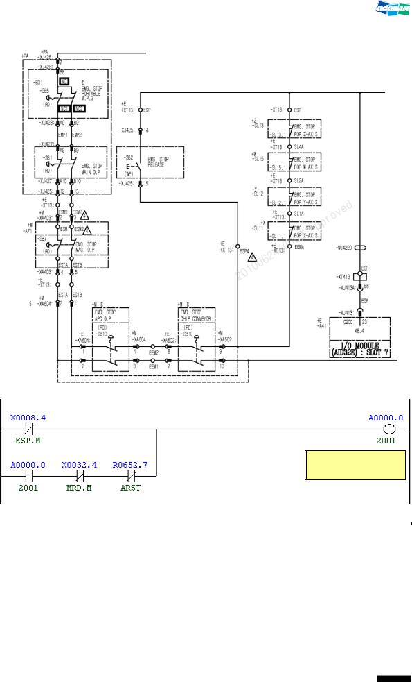
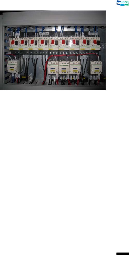
1.52005 Hyd. Pressure Down Alarm
1)Description
The pressure of the hydraulic power unit falls below the setting value of the hydraulic pressure switch, causing the hydraulic pressure switch to be tripped.
2)Cause of problem
The hydraulic power unit has an error or its pressure falls below 20kg/ .
The hydraulic pressure switch or any of its parts is defective.
3)Action
Turn the pressure value of the hydraulic power unit clockwise to adjust the pressure to 50kg/ .
The pressure switch of the hydraulic power unit has an error, or the wiring or related component parts are defective.
Check the hydraulic power unit, the pressure switch, and the wiring from the switch to the electric cabinet as well as the I/O board, and make repair or replacement if you find a problem.
Part Name |
|
Part No. |
|
Symbol |
|
Spec. |
|
Maker |
|
|||
|
|
|
|
|
||||||||
Cable, Pressure Switch |
ECBLS0167F |
|
-WK11 |
|
BKS B19-1-05 |
|
BALUFF |
|
||||
|
|
|
|
|
|
|
|
|
|
|
|
|
Switch Pressure |
|
R37983 |
|
-SP01 |
|
EDS810-060-0-024 |
|
HYDACS |
|
|||
|
|
|
|
|
|
|
|
|
|
|
|
|
|
|
|
|
|
|
|
|
|
|
|||
Signal |
Address |
Device |
|
I/O |
|
Connector |
|
Numbering |
|
|||
|
|
|
Symbol |
|
|
|
|
(Pin) |
|
|
|
|
Hyd. Pressure Check |
|
X8.3 |
-SP31 |
Input Module Slot 7 |
XJ413(6) |
|
SP31 |
|
||||
HDPS.M |
|
|
||||||||||
Hydraulic Motor Run |
|
Y2.0 |
-KA31A |
Output Module Slot |
(02) |
|
KA31A |
|
||||
HYDM.R |
2 |
|
|
|
|
|||||||
|
|
|
|
|
|
|
|
|
||||
|
|
|
|
|
|
|
|
|
|
|
||
|
|
|
|
|
|
|
|
|
Main Hyd. Pump |
|
||
|
|
|
|
|
|
|
|
|
Pressure Switch |
|
||
|
|
|
|
|
|
|
|
|
|
|
|
|
12
DBC 130(F30i Series) |
DBC130ALE2A |
|
|
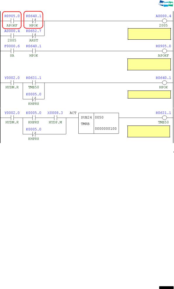
Hydraulic Pressure
Down
Aux. Hyd. Pressure
O.K Flag
Hyd. Pressure O.K
Hyd. Pressure Check
Delay Time
Address |
Symbol |
Coil Comment |
|
|
|
|
|
R905.0 |
APOKF |
Aux. Hyd. Pressure OK Flag |
|
|
|
|
|
R640.1 |
HPOK |
Hyd. Pressure OK |
|
|
|
|
|
A0.4 |
2005 |
Hyd. Pressure Down Alarm |
|
|
|
|
|
R652.7 |
ARST |
Alarm Reset |
|
|
|
|
|
F0.6 |
SA |
Servo Ready |
|
|
|
|
|
Y2.0 |
HYDM.R |
Hyd. Pump Motor Run |
|
|
|
|
|
R631.1 |
TMB50 |
Hyd. Pressure Check Delay Time |
|
|
|
|
|
K5.0 |
KHPRS |
Hyd. Pressure SW Used |
|
|
|
|
|
X8.3 |
HYDP.M |
Hyd. Pressure Check |
|
|
|
|
13

DBC 130(F30i Series) |
DBC130ALE2A |
|
|
1.62006 Spindle Gear Shift Check Switch Alarm
1)Description
3 or more of 4 check switches (Low, Middle, High, etc) on the spindle head gear range were tripped, or none of them was tripped.
2)Cause of problem
The check switch for the main spindle gear range has short-circuited or any of its component parts is defective.
3)Action
Check the gear box switch of the main spindle if it works properly on the DGN screen, and take a necessary measure.
Note 1) Spindle Gear Shifting I/O Settings
Signal |
Address |
Device |
I/O |
Connector |
Numbering |
|
|
|
Symbol |
|
(Pin) |
|
|
Gear 1 Check |
X3.0 (SGA.M) |
-SL11 |
Input Module Slot 06 |
XJ412 (12) |
SL11 |
|
|
|
|
|
|
|
|
Gear 2 Check |
X3.2 (SGB.M) |
-SL13 |
Input Module Slot 06 |
XJ412 (44) |
SL13 |
|
|
|
|
|
|
|
|
Gear 3 Check |
X3.3 (SGC.M) |
-SL14 |
Input Module Slot 06 |
XJ412 (11) |
SL14 |
|
|
|
|
|
|
|
|
Gear 4 Check |
X3.4 (SGD.M) |
-SL15 |
Input Module Slot 06 |
XJ412 (27) |
SL15 |
|
|
|
|
|
|
|
|
Spindle Gear 1 |
Y4.0 (GR1.V) |
-KAR40 |
Output Module Slot 3 |
XJ400 (16) |
YV14 |
|
|
|
|
|
|
|
|
Spindle Gear 2 |
Y4.1 (GR2.V) |
-KAR41 |
Output Module Slot 3 |
XJ400 (32) |
YV15 |
|
|
|
|
|
|
|
|
Spindle Gear 3 |
Y4.2 (GR3.V) |
-KAR42 |
Output Module Slot 3 |
XJ400 (48) |
YV18 |
|
|
|
|
|
|
|
|
Spindle Gear 4 |
Y4.3 (GR4.V) |
-KAR43 |
Output Module Slot 3 |
XJ400 (15) |
YV19 |
|
|
|
|
|
|
|
Note 2) Spindle Gear Range Shifting RPM (D460~D462)
Data of the data table---0002/0011(gear shift rpm)
ADDRESS NO. DATA MEANING
D0460 #  0000 25 Gear shift rpm in gear1 range
D0461 #  0001 25 Gear shift rpm in gear2 range
D0462 #  0002 25 Gear shift rpm in gear3 range
14

DBC 130(F30i Series) |
DBC130ALE2A |
|
|
Note 3) How to move to DGN (Diagnostic)
(1)Press the “SYSTEM” button in the right side of the main OP monitor.
The following soft key bar will be displayed at the bottom.
(2)Move to the DGN screen.
Press the soft keys one after another to move to the DGN screen.
Press any soft key in the right corner to activate the vertical soft key bar, and press the [STATUS] key.
1 |
2 |
Activate the vertical soft key
(3)Enter a desired DGN address and press [SEARCH] to display the DGN screen of your choice.
15

DBC 130(F30i Series) |
DBC130ALE2A |
|
|
Note 4) How to read DGN (Diagnostic)
Ex) X 0007 |
0 0 1 1 0 0 1 0 |
Bit 1, 4 and 5 in Address X7 turn ON while Bit 0, 2, 3, 6 and 7 turn OFF.
Symbol |
0 |
0 |
1 |
1 |
0 |
0 |
1 |
0 |
|
Bit No |
Bit 7 |
Bit 6 |
Bit 5 |
Bit 4 |
Bit 3 |
Bit 2 |
Bit 1 |
Bit 0 |
|
|
|
|
|
|
|
|
|
|
Note 5) Hydraulic circuit diagram of the spindle head
|
|
Gear Shift |
|
|
|
Tool Unclamp |
|
SL11 |
1 |
2 |
SL13 |
SL14 |
3 |
4 |
SL15 |
SL12
|
|
|
|
YV15 |
YV14 |
|
YV19 |
YV18 |
|
|
YV11 |
|
|
||
|
|
|
P |
|
|
|
|
|
|
|
|
|
|
|
|
|
|
|
|
|
|
|
|
|
|
|
|
|
|
|
|
|
|
|
|
|
|
|
|
|
|
|
|
|
|
|
|
|
|
|
T |
|
|
|
|
|
|
|
|
|
|
|
|
|
|
|
|
|
|
|
|
|
|
|
|
|
|||
|
|
|
|
|
|
|
|
|
|
|
|
|
|
|
|
Note 6) Spindle Gear |
Selection Table |
|
|
|
|
|
|
|
|
|
|||||
|
|
|
|
|
|
|
|
|
|
|
|
|
|
|
|
|
Gear |
Keep |
S-Code |
|
|
Input Signal |
|
|
Output Signal |
|
|
||||
|
X3.0 |
|
X3.2 |
X3.3 |
X3.4 |
Y4.3 |
Y4.2 |
Y4.1 |
Y4.0 |
||||||
|
State |
Relay |
|
||||||||||||
|
|
SL11 |
|
SL13 |
SL14 |
SL15 |
YV19 |
YV18 |
YV15 |
YV14 |
|||||
|
|
|
|
|
|
|
|||||||||
|
High |
K75.5 |
S0~S246 |
1 |
|
0 |
1 |
0 |
0 |
1 |
0 |
1 |
|||
|
Middle |
K75.6 |
S247~S806 |
1 |
|
0 |
0 |
1 |
1 |
0 |
0 |
1 |
|||
|
|
Low |
K75.7 |
S807~S2500 |
0 |
|
1 |
0 |
1 |
1 |
0 |
1 |
0 |
||
16

DBC 130(F30i Series) |
|
DBC130ALE2A |
|
SL14 |
SL15 |
SL11 |
SL13 |
|
Spindle Gear Shift
Check Switch Alarm
Gear Shift End Flag
17

DBC 130(F30i Series) |
DBC130ALE2A |
|
|
Gear Shift O.K
|
|
|
Gear Shift Range |
|
|
|
|
Low |
|
|
|
|
|
|
|
|
|
Gear Shift Range |
|
|
|
|
Middle |
|
|
|
|
|
|
|
|
|
Gear Shift Range |
|
|
|
|
High |
|
|
|
|
|
|
Address |
Symbol |
Coil Comment |
||
R905.1 |
GSTEND |
Gear Shift End Flag |
||
|
|
|
|
|
R684.6 |
GOK |
Gear Shift O.K |
||
|
|
|
|
|
X3.0 |
SGA.M |
Spindle Gear A/S-Unclamp Built |
||
|
|
|
|
|
X3.2 |
SGB.M |
Spindle Gear Shift Status B |
||
|
|
|
|
|
X3.3 |
SGC.M |
Spindle Gear Shift Status C |
||
|
|
|
|
|
X3.4 |
SGD.M |
Spindle Gear Shift Status D |
||
|
|
|
|
|
R684.2 |
GSHON |
Gear Shift On |
||
|
|
|
|
|
A0.5 |
2006 |
Gear Shift Check Switch Alarm |
||
|
|
|
|
|
R652.7 |
ARST |
Alarm Reset |
||
|
|
|
|
|
R905.1 |
GSTEND |
Gear Shift End Flag |
||
|
|
|
|
|
R683.4 |
SGRL |
Spindle Gear Shift Low |
||
|
|
|
|
|
R683.5 |
SGRM |
Spindle Gear Range Middle |
||
|
|
|
|
|
R683.6 |
SGRH |
Spindle Gear Range High |
||
|
|
|
|
|
18
DBC 130(F30i Series) |
DBC130ALE2A |
|
|
1.72008 PSM Contact Check Error
1)Description
There occurred an error while KM10 magnetic contactor was operating.
2)Cause of problem
The operation of KM10 did not comply with the intended signal.
3)Action
The check signal (X9.6) of the magnetic contactor should turn on only while KM10 is operating.
Set "Keep Relay K17.0" to 1 if you want to enable the option of Motor Power On/Off.
If you set "K17.0=(1)" to enable the option of Motor Power ON/OFF, KM10 magnetic contactor turns off if the door is open, and turns on if the door is close.
Signal |
Address |
Device |
I/O |
Connector |
Numbering |
|
|
|
Symbol |
|
(Pin) |
|
|
Power Supply Contact |
X9.6 |
-KM10 |
Input Module Slot 07 |
XJ413 (01) |
PMON |
|
On State |
PMON.M |
|||||
|
|
|
|
|||
Splash Guard Door |
X6.2 |
-S61 |
Input Module Slot 07 |
XJ413(48) |
SS61B |
|
Interlock |
SDIC.M |
|||||
|
|
|
|
KM10 (Magnet)
Auxiliary “a” contact
KM10
(Magnet)
19

DBC 130(F30i Series) |
DBC130ALE2A |
|
|
PSM Contact Check
Error
|
|
|
Power Module Alarm |
|
|
|
|
Check Time |
|
|
|
|
|
|
Address |
Symbol |
Coil Comment |
||
|
|
|
|
|
R633.5 |
TMB70 |
Power Module Alarm Check Time |
||
|
|
|
|
|
A0.7 |
2008 |
PSM Contact Check Error |
||
|
|
|
|
|
R652.7 |
ARST |
Alarm Reset |
||
|
|
|
|
|
G8.4 |
B.ESP |
Emergency Stop |
||
|
|
|
|
|
X6.2 |
SDIC.M |
Splash Guard Door Interlock |
||
|
|
|
|
|
R634.0 |
TMB73 |
Connect Delay Time Again |
||
|
|
|
|
|
X9.6 |
PMON.M |
Power Supply Magnet On State |
||
|
|
|
|
|
K17.0 |
KMPOFF |
Module Elec. Off D-Open |
||
|
|
|
|
|
F0.6 |
SA |
Servo Ready |
||
|
|
|
|
|
X17.7 |
MENB.M |
Machine Enable Switch On |
||
|
|
|
|
|
20

DBC 130(F30i Series) |
DBC130ALE2A |
|
|
2.Cycle Alarm
2.12031 Return to Ref. Point in Manual
1)Description
A message prompting you to manually return the axis to the reference point
2)Cause of problem
The machine was instructed to operate before all axes had returned to their respective reference point.
In the Machine Lock state, AUTO mode (EDIT, MEMORY, TAPE, MDI) was selected. (X, Y, Z, W)
In the Machine Lock state, EDIT or MEMORY mode was selected. (B, 6 axes)
3)Action
Return to the reference point manually
If you want to operate the machine regardless of whether the axes return to their reference point, set "Keep Relay K1.6" to 1.
In the Machine Lock state, the machine can be instructed to operate in AUTO mode only after the axes have returned to their respective reference point.
Return to Ref. Point
Manually
Ref. Point Return
Interlock. Alarm
21

DBC 130(F30i Series) |
DBC130ALE2A |
|
|
Machine Lock on
Flag X, Y, Z, W
Home Position
Interlock
Address |
Symbol |
Coil Comment |
|
|
|||
R906.1 |
HOMIAL |
Ref. Point Return Interlock Alarm |
|
|
|
|
|
R648.7 |
MLKFA |
Machine Lock On Flag X, Y, Z, W |
|
|
|
|
|
R642.2 |
AUT |
Auto Mode |
|
|
|
|
|
R648.6 |
MLKFB |
Machine Lock On Flag B-Axis |
|
|
|
|
|
R1100.6 |
MLKF6 |
Machine Lock On Flag 6-Axis |
|
|
|
|
|
R641.1 |
MEM |
Memory Mode |
|
|
|
|
|
R641.2 |
TAPE |
Tape Mode |
|
|
|
|
|
A26.7 |
2216 |
Must Be Return to Ref. Point X |
|
|
|
|
|
A27.0 |
2217 |
Must Be Return to Ref. Point Y |
|
|
|
|
|
A27.1 |
2218 |
Must Be Return to Ref. Point Z |
|
|
|
|
|
A27.2 |
2219 |
Must Be Return to Ref. Point W |
|
|
|
|
|
A27.3 |
2220 |
Must Be Return to Ref. Point B |
|
|
|
|
|
A27.5 |
2222 |
6th Axis Clamp/Unclamp Alarm |
|
22

DBC 130(F30i Series) |
|
DBC130ALE2A |
|
|
|
|
|
|
|
|
|
|
|
|
|
Address |
Symbol |
Coil Comment |
|
|
|
|
|
|
|
A3.6 |
2031 |
Return to Ref. Point in Manual |
|
|
|
|
|
|
|
X32.5 |
ST.M |
Cycle Start |
|
|
|
|
|
|
|
R652.7 |
ARST |
Alarm Reset |
|
|
|
|
|
|
|
R646.7 |
HOMINT |
Home Position Interlock |
|
|
|
|
|
|
|
G62.6 |
RTNT |
Rigid Tapping Retraction Start |
|
|
|
|
|
|
|
R648.0 |
MLKX |
Machine Lock X-Axis |
|
|
|
|
|
|
|
R648.1 |
MLKY |
Machine Lock Y-Axis |
|
|
|
|
|
|
|
R648.3 |
MLKW |
Machine Lock W-Axis |
|
|
|
|
|
|
|
G44.1 |
MLK |
Machine Lock |
|
|
|
|
|
|
|
R648.2 |
MLKZ |
Machine Lock Z-Axis |
|
|
|
|
|
|
|
G108.2 |
ZMLK |
Z-Axis Machine Lock |
|
|
|
|
|
|
|
G108.3 |
WMLK |
W-Axis Machine Lock |
|
|
|
|
|
|
|
K3.1 |
KMLKI |
Machine Lock Ref. Point Invalid |
|
|
|
|
|
|
23

DBC 130(F30i Series) |
DBC130ALE2A |
|
|
2.22032 Feed Hold Push Button is Pressed
1)Description
An error in the signal of the feed hold switch while the program is running (in AUTO mode)
2)Cause of problem
The feed hold switch on the main OP is tripped.
The feed hold switch enables you to stop running the program instantly without instructing the emergency stop.
A short-circuit or defective part in the feed hold switch
3)Action
If you have pressed the feed hold switch by necessity, release the switch to set off the
alarm. Then, you can press the Cycle Start switch to resume running the program.
Turn the feed hold switch manually to check the input signal on the DGN screen of PMC. Take necessary measures (reconnect the wiring, etc) to restore normal conditions.
Signal |
Address |
Device |
I/O |
Connector |
Numbering |
|
Symbol |
(Pin) |
|||||
|
|
|
|
|||
Feed Hold |
X32.6 |
-SB17 |
Distribute I/O |
XCE56A(A05) |
SB17 |
|
SP.M |
Module(A) |
|||||
|
|
|
|
|
|
|
Feed Hold Push |
|
|
|
|
Button is Pressed |
|
|
|
|
|
|
Address |
Symbol |
Coil Comment |
||
|
|
|
|
|
X32.6 |
SP.M |
Cycle Stop |
||
|
|
|
|
|
R642.2 |
AUT |
Auto Mode |
||
|
|
|
|
|
F0.5 |
STL |
Cycle Start |
||
|
|
|
|
|
F0.4 |
SPL |
Feed Hold |
||
|
|
|
|
|
R640.2 |
SPCLFH |
Spindle & Coolant At Feed Hold |
||
|
|
|
|
|
R640.5 |
CYSTP |
Cycle Stop |
||
|
|
|
|
|
A3.7 |
2032 |
Feed Hold Push Button is Pressed |
||
|
|
|
|
|
24

DBC 130(F30i Series) |
DBC130ALE2A |
|
|
Feed Hold
25

DBC 130(F30i Series) |
DBC130ALE2A |
|
|
2.32033 Air Pressure down Alarm
1)Description
The air pressure switch is tripped because the air pressure falls below the specified value.
2)Cause of problem
The factory-supplied air pressure falls below the standard (4kg).
The air pressure switch or any of its parts is defective.
3)Action
Increase the factory-supplied air pressure to more than 5kg/ .
▪Check the air pressure measurement displayed on the gauge of the air service unit, and if it's below 4kg/ , turn the air pressure handle to the right. If the gauge does not increase
any further, this indicates the current air pressure is not appropriate.
Check the air pressure switch, wiring and I/O module if there is no error. And make repair or replacement if necessary.
Signal |
Address |
Device |
I/O |
Connector |
Numbering |
|
|
|
Symbol |
|
(Pin) |
|
|
Main Air Pressure |
X4.2 |
-SP8C |
Input Module : |
XJ412 (39) |
SP8C |
|
Check |
MAC.M |
Slot 06 |
||||
|
|
|
Air Pressure Down
Alarm
Main Air Check
D-Time
26

DBC 130(F30i Series) |
|
DBC130ALE2A |
|
|
|
|
|
|
|
|
|
|
|
|
|
Address |
Symbol |
Coil Comment |
|
|
X4.2 |
MAC.M |
Main Air Pressure Check |
|
|
|
|
|
|
|
R638.7 |
TMB112 |
Main Air Check D-Time |
|
|
A4.0 |
2033 |
Air Pressure Down Alarm |
|
|
|
|
|
|
|
R652.7 |
ARST |
Alarm Reset |
|
|
X7.0 |
MSOP.M |
Mist Oil Operating Pressure |
|
|
K4.0 |
KBLTSP |
Built In Spindle Used |
|
|
|
|
|
|
|
F0.6 |
SA |
Servo Ready |
|
|
|
|
|
|
Air Pressure
Adjustable Valve
Air Pressure
Switch (SP8C)
Air Supply Unit
27

DBC 130(F30i Series) |
DBC130ALE2A |
|
|
2.42034 Coolant & Lub. Pump Overload
1)Description
An excessive electric current is detected in the coolant or lubricant pump motor.
2)Cause of problem
The coolant or lubricant pump motor, or the power cable is burnt out.
The circuit breaker that detects the excessive current is overloaded or defective itself.
3)Action
Check the coolant or lubricant pump motor, or the power cable, and repair or replace a defective one if found.
Check the circuit breaker for the load settings and make correction if necessary. If the circuit breaker itself has an error, replace it with a new one.
Overload settings |
|
|
|
|
|
|
|
|
|
|
||||
QM41 (Flood Coolant Pump Motor) |
: 1.5 Kw : 7 A / 2.2 Kw : 11 A |
|
|
|
||||||||||
QM42 (T-T-S Coolant Pump Motor) |
: 1.5 Kw : 7 A / 3.7 Kw : 17 A |
|
|
|
||||||||||
QM43 (Cool Jet T-S-C Unit) |
|
|
: 5.5 Kw : 23.9 A / 3.7Kw : 17A |
|
|
|
||||||||
QM422 (Recovery Pump Motor/C-J) |
: 0.9 Kw : 5.2 A |
|
|
|
|
|||||||||
|
|
|
|
|
|
|
|
|
|
|
|
|
|
|
Part Name |
|
Part No. |
|
Symbol |
|
|
Spec. |
|
Maker |
|
||||
|
|
|
|
|
|
|
|
|
|
|
|
|
||
Breaker, Auxiliary |
|
ENFBX0290M |
QM41,42,43,422 |
|
TESYS. GV2ME22. 20-25A |
Schneider |
|
|||||||
|
|
|
|
|
|
|
|
|
|
|
|
|
||
Breaker, Motor Circuit |
|
ENFBX0259M |
QM41,QM42 |
|
TESYS. GV2ME14. 6-10A |
Schneider |
|
|||||||
|
|
|
|
|
|
|
|
|
|
|
|
|
|
|
Breaker, Motor Circuit |
|
ENFBX0285M |
|
QM41 |
|
TESYS. GV2ME16. 9-14A |
Schneider |
|
||||||
|
|
|
|
|
|
|
|
|
|
|
|
|
||
Breaker, Motor Circuit |
|
ENFBX0261M |
QM42, QM43 |
|
TESYS. GV2ME21. 17-23A |
Schneider |
|
|||||||
|
|
|
|
|
|
|
|
|
|
|
|
|
|
|
Breaker, Motor Circuit |
|
ENFBX0262M |
|
QM43 |
|
TESYS. GV2ME22. 20-25A |
Schneider |
|
||||||
|
|
|
|
|
|
|
|
|
|
|
|
|
|
|
Breaker, Motor Circuit |
|
ENFBX0258M |
|
QM422 |
|
TESYS. GV2ME10. 4-6.3A |
Schneider |
|
||||||
|
|
|
|
|
|
|
|
|
|
|
|
|
|
|
|
|
|
|
|
|
|
|
|
|
|
|
|
|
|
Signal |
|
Address |
|
Device |
|
I/O |
|
Connector |
Numbering |
|
||||
|
|
Symbol |
|
|
(Pin) |
|
||||||||
|
|
|
|
|
|
|
|
|
|
|
|
|||
Coolant & Lub. |
|
|
X2.2 |
|
-M213 |
|
Input Module : |
XJ411 (48) |
|
M213 |
|
|||
Motor Overload |
|
MOVL.M |
|
|
Slot 06 |
|
|
|||||||
|
|
|
|
|
|
|
|
|
||||||
Coolant Motor
Overload Alarm
28
 Loading...