


SB2215E01
O c t . 2 0 0 1
Service Manual
G424 Gasoline/LP Engine
G424 LP Engine (Low Emission Version)
G20E-3, G25E-3, G30E-3
GC20E-3, GC25E-3, GC30E-3

Important Safety Information
Most accidents involving product operation, maintenance and repair are caused by failure to observe basic safety rules or precautions. An accident can often be avoided by recognizing potentially hazardous situations before an accident occurs. A person must be alert to potential hazards. This person should also have the necessary training, skills and tools to perform these functions properly.
Read and understand all safety precautions and warnings before operating or performing lubrication, maintenance and repair on this product.
Basic safety precautions are listed in the “Safety” section of the Service or Technical Manual. Additional safety precautions are listed in the “Safety” section of the owner/operation/maintenance publication.
Specific safety warnings for all these publications are provided in the description of operations where hazards exist. WARNING labels have also been put on the product to provide instructions and to identify specific hazards. If these hazard warnings are not heeded, bodily injury or death could occur to you or other persons. Warnings in this publication and on the product labels are identified by the following symbol.
 WARNING
Improper operation, lubrication, maintenance or repair of this product can be dangerous and could result in injury or death.
Do not operate or perform any lubrication, maintenance or repair on this product, until you have read and understood the operation, lubrication, maintenance and repair information.
Operations that may cause product damage are identified by NOTICE labels on the product and in this publication.
DAEWOO cannot anticipate every possible circumstance that might involve a potential hazard. The warnings in this publication and on the product are therefore not all inclusive. If a tool, procedure, work method or operating technique not specifically recommended by DAEWOO is used, you must satisfy yourself that it is safe for you and others. You should also ensure that the product will not be damaged or made unsafe by the operation, lubrication, maintenance or repair procedures you choose.
The information, specifications, and illustrations in this publication are on the basis of information available at the time it was written. The specifications, torques, pressures, measurements, adjustments, illustrations, and other items can change at any time. These changes can affect the service given to the product. Obtain the complete and most current information before starting any job. DAEWOO dealers have the most current information available.
1

Index
GENERAL INFORMATION |
....................................... |
||||||||||||||||||||||||||||
|
|
|
|
|
|
|
|
|
|
4 |
|||||||||||||||||||
How to Read This Manual |
.................................... |
||||||||||||||||||||||||||||
|
|
|
|
|
|
|
|
4 |
|||||||||||||||||||||
Precaution Before Service |
.................................... |
||||||||||||||||||||||||||||
|
|
|
|
|
|
|
|
6 |
|||||||||||||||||||||
General |
................................................................. |
||||||||||||||||||||||||||||
|
|
|
|
|
|
|
|
|
|
|
|
|
|
|
|
|
|
|
|
|
|
|
|
|
|
8 |
|||
Tightening Torque |
................................................. |
||||||||||||||||||||||||||||
|
|
|
|
|
|
|
|
|
|
|
|
|
|
|
|
|
|
9 |
|||||||||||
Sealant |
................................................................ |
12 |
|||||||||||||||||||||||||||
|
|
|
|
|
|
|
|
|
|
|
|
|
|
|
|
|
|
|
|
|
|
|
|
|
|
|
|||
SPECIFICATIONS |
................................................... |
13 |
|||||||||||||||||||||||||||
|
|
|
|
|
|
|
|
.......................................... |
|||||||||||||||||||||
General Specification |
13 |
||||||||||||||||||||||||||||
.......................................... |
|||||||||||||||||||||||||||||
Service Specification |
14 |
||||||||||||||||||||||||||||
|
|
|
|
|
|
|
|
|
|
|
|
|
|
||||||||||||||||
MAINTENANCE |
...................................................... |
17 |
|||||||||||||||||||||||||||
|
|
|
|
|
|
|
|
|
|
|
|
|
|
|
|
|
................................ |
||||||||||||
Test Fuel System for Leaks |
17 |
||||||||||||||||||||||||||||
|
|
|
|
|
|
|
|||||||||||||||||||||||
Check Engine Oil Level |
...................................... |
17 |
|||||||||||||||||||||||||||
|
|
|
|
|
|
|
........................... |
||||||||||||||||||||||
Inspect Engine for Fluid Leaks |
17 |
||||||||||||||||||||||||||||
|
|
|
|
||||||||||||||||||||||||||
Change Engine Oil and Filter |
............................. |
17 |
|||||||||||||||||||||||||||
|
|
|
|
|
|||||||||||||||||||||||||
Inspect Accessory Drive Belts ............................ |
|
|
|
|
18 |
||||||||||||||||||||||||
|
|
|
|
|
|
|
|
|
|
|
|
|
|
|
|
|
|
|
.................................... |
||||||||||
Inspect Electrical System |
18 |
||||||||||||||||||||||||||||
|
|
|
|
|
|
......................... |
|||||||||||||||||||||||
Inspect Vacuum lines and fitting |
18 |
||||||||||||||||||||||||||||
|
|
|
|||||||||||||||||||||||||||
Check Coolant Level |
........................................... |
18 |
|||||||||||||||||||||||||||
|
|
|
........................................ |
||||||||||||||||||||||||||
Inspect Coolant Hoses |
18 |
||||||||||||||||||||||||||||
|
|
|
|
|
|
|
|
|
|
|
|
||||||||||||||||||
Inspect Ignition System....................................... |
|
|
|
|
|
|
|
|
|
|
|
18 |
|||||||||||||||||
Replace Spark Plug |
............................................ |
18 |
|||||||||||||||||||||||||||
|
|
|
|
|
|
|
|
|
|
|
............................. |
||||||||||||||||||
Replace LP fuel filter element |
19 |
||||||||||||||||||||||||||||
Test Fuelock (electric) |
......................................... |
19 |
|||||||||||||||||||||||||||
|
|
|
|
|
|
|
............................... |
||||||||||||||||||||||
Replace Gasoline Fuel filter |
20 |
||||||||||||||||||||||||||||
............................... |
|||||||||||||||||||||||||||||
Inspect Gasoline Carburetor |
20 |
||||||||||||||||||||||||||||
|
|
|
|
|
................ |
||||||||||||||||||||||||
Inspect Pressure Regulator/Vaporizer |
20 |
||||||||||||||||||||||||||||
................ |
|||||||||||||||||||||||||||||
Inspect LP Mixer (Standard LP Truck) |
20 |
||||||||||||||||||||||||||||
|
|||||||||||||||||||||||||||||
Inspect Variable Venturi Air/Fuel Mxer |
|
||||||||||||||||||||||||||||
(Low Emission LP Truck) |
.................................... |
|
|
|
|
|
|
|
|
20 |
|||||||||||||||||||
Inspect Complete Exhaust System for |
|
||||||||||||||||||||||||||||
Leaks,damage |
.................................................... |
20 |
|||||||||||||||||||||||||||
|
|
|
|
|
|
|
|
|
|
|
|
|
|
|
|
|
|
|
|
|
|
|
|||||||
Engine Control Unit (ECU) and others |
|
||||||||||||||||||||||||||||
(Low Emission LP Truck) |
.................................... |
|
|
|
|
|
|
|
|
20 |
|||||||||||||||||||
Maintenance Schedule |
|
|
|
|
|
|
|
|
|
|
|
||||||||||||||||||
|
|
|
|
|
|
|
|
|
|
|
21 |
||||||||||||||||||
|
|
|
|
|
|
|
|
|
|
|
|
|
|
|
|
|
|
|
|
|
|
|
|
|
|
|
|
||
ENGINE SYSTEM |
|
................................................... |
22 |
||||||||||||||||||||||||||
|
|
|
................................................. |
||||||||||||||||||||||||||
Engine Overview |
22 |
||||||||||||||||||||||||||||
Timing System |
.................................................... |
25 |
|||||||||||||||||||||||||||
|
|
|
|
|
|
|
|
|
|
|
|
...................................... |
|||||||||||||||||
Silent Shaft Mechanism |
26 |
||||||||||||||||||||||||||||
|
|
|
|
|
|
|
|
|
|
|
|||||||||||||||||||
Auto Lash Adjuster |
.............................................. |
27 |
|||||||||||||||||||||||||||
|
|
|
|
|
|
|
|
|
|
................................ |
|||||||||||||||||||
Intake and Exhaust System |
28 |
||||||||||||||||||||||||||||
|
|
|
|
|
|
|
|||||||||||||||||||||||
Electrical System |
................................................ |
30 |
|||||||||||||||||||||||||||
|
|
|
|
|
|
|
|
|
|
|
|
|
|
|
|
|
|
|
|||||||||||
STARTING SYSTEM |
............................................... |
32 |
|||||||||||||||||||||||||||
|
|
............................................ |
|||||||||||||||||||||||||||
General Description |
32 |
||||||||||||||||||||||||||||
|
|
|
|
|
|
|
|
|
|
|
|
|
|
|
|
||||||||||||||
Start Relay Test |
.................................................. |
35 |
|||||||||||||||||||||||||||
|
|
|
|
|
|
|
|
|
|
|
|
|
|
|
|
|
|
|
|
|
|||||||||
Start Motor |
.......................................................... |
36 |
|||||||||||||||||||||||||||
|
....................................................... |
||||||||||||||||||||||||||||
Operation |
36 |
||||||||||||||||||||||||||||
|
|
|
|
|
|
|
|
|
|
|
|
|
|
|
|
|
|
............................... |
|||||||||||
Removal and Installation |
39 |
||||||||||||||||||||||||||||
|
|
|
|
...................... |
|||||||||||||||||||||||||
Disassembly and Reassembly |
42 |
||||||||||||||||||||||||||||
|
|
||||||||||||||||||||||||||||
CHARGING SYSTEM |
.............................................. |
47 |
|||||||||||||||||||||||||||
|
............................................ |
||||||||||||||||||||||||||||
General Description |
47 |
||||||||||||||||||||||||||||
|
|
|
|
|
|
|
|
|
|
|
|
|
|
|
|
||||||||||||||
Alternator |
............................................................ |
47 |
|||||||||||
|
|
|
|
|
|
|
|
|
|
|
|||
IGNITION SYSTEM ................................................. |
|
|
|
|
|
|
|
|
50 |
||||
Breakerless Ignition System |
|
||||||||||||
|
50 |
||||||||||||
Distributor |
|
|
|
|
|
|
|
|
|
|
|
||
............................................................ |
|
|
|
|
|
|
.................................... |
51 |
|||||
|
|
|
|
|
|
|
|
||||||
Removal and Installation |
54 |
||||||||||||
|
|
|
|
||||||||||
Distributor, disassembly and reassembly ........... |
56 |
||||||||||||
|
|
|
|
|
|
|
|
|
|
|
|
||
GASOLINE FUEL SYSTEM |
.................................... |
58 |
|||||||||||
|
|
|
|
||||||||||
General Description |
............................................ |
|
|
|
|
|
58 |
||||||
Geasoline Carburetor, Operation |
|||||||||||||
59 |
|||||||||||||
|
|
|
|
|
|
|
|
.................................... |
|||||
Removal and Installation |
64 |
||||||||||||
|
|
|
|
||||||||||
Gasoline Carburetor |
|
|
|
|
|
|
|||||||
Disassembly and Reassembly............................ |
66 |
||||||||||||
|
|
|
|
|
|
|
|
|
|
|
|
||
LPG FUEL SYSTEM ............................................... |
|
............................................ |
73 |
||||||||||
|
|
|
|
|
|
||||||||
General Description |
73 |
||||||||||||
|
|
|
|
.................................. |
|||||||||
Electric Fuelock Model |
73 |
||||||||||||
Converter |
....................................................... |
74 |
|||||||||||
....................................................... |
|||||||||||||
Fuel Tank |
75 |
||||||||||||
|
|
|
.............................................. |
||||||||||
LP Relief Valve |
75 |
||||||||||||
|
|
|
|
|
|
|
|||||||
Carburetor |
..................................................... |
76 |
|||||||||||
|
|
|
|
........................................... |
|||||||||
Tests or Adjustments |
77 |
||||||||||||
|
|
|
.................................. |
||||||||||
Carburetor Adjustment |
77 |
||||||||||||
|
.............................. |
||||||||||||
Fuel System Leak Check |
79 |
||||||||||||
|
|||||||||||||
Recommendation for LP Fuel System .......... |
80 |
||||||||||||
|
|
|
|
|
|
|
|
|
|
|
|
||
LP Converter - Check, Clean ........................ |
81 |
||||||||||||
Disassembly and Assembly ................................ |
|
82 |
|||||||||||
LPG Carburetor |
|
|
|
|
|
|
|||||||
|
|
|
|
|
|
82 |
|||||||
LP Gas Fuelock |
|
|
|
|
|
|
|||||||
|
|
|
|
|
|
84 |
|||||||
|
|
|
|
|
|
|
|
|
|
|
|
||
LP Gas Converter.......................................... |
|
|
|
|
85 |
||||||||
LPG FUEL SYSTEM (LOW EMISSION VERSION)..87 |
|||||||||||||
General Description |
............................................ |
87 |
|||||||||||
|
|
|
|
|
|
||||||||
LP Carburetor |
................................................ |
89 |
|||||||||||
|
|
|
|
|
................................... |
||||||||
Vacuum switch (MAP) |
90 |
||||||||||||
|
|
|
|||||||||||
Vacuum switch |
.............................................. |
|
|
|
|
|
|
90 |
|||||
LP Converter |
|
|
|
|
|
|
|
|
|||||
|
|
|
|
|
|
|
|
91 |
|||||
Fuel Control Valve |
|
|
|
|
|||||||||
|
|
|
|
92 |
|||||||||
Fuelock Valve |
................................................ |
|
|
|
|
|
|
|
92 |
||||
Engine Control Unit (ECU) |
|||||||||||||
93 |
|||||||||||||
Oxygen Sensor |
|
|
|
|
|
|
|
||||||
.............................................. |
|
|
|
|
|
|
94 |
||||||
Catalytic Muffler |
|
|
|
|
|
|
|||||||
|
|
|
|
|
|
95 |
|||||||
Tests or Adjustments |
|
|
|
|
|
||||||||
|
|
|
|
|
96 |
||||||||
|
|
|
|
|
|
|
|
|
|
|
|
||
LP Carburetor - Check, Clean....................... |
97 |
||||||||||||
LP Converter-Check,Clean ........................... |
97 |
||||||||||||
Inspection of Fuelock Valve |
|||||||||||||
97 |
|||||||||||||
Inspection of Fuel Control Valve |
|||||||||||||
97 |
|||||||||||||
Inspection of Vacuum switch |
|||||||||||||
97 |
|||||||||||||
Inspection of Vacuum switch (MAP) |
|||||||||||||
97 |
|||||||||||||
Inspection of Oxygen sensor......................... |
98 |
||||||||||||
|
|
|
|
|
|
|
|
|
|
|
|
||
Disassembly and Assembly |
................................99 |
|
LPG Carburetor |
||
99 |
||
|
||
LP Gas Converter........................................ |
101 |
|
|
G424 Service Manual |
2 |
Index |

DUAL FUEL SYSTEM |
........................................... |
102 |
||||||||||||||||||||||||||
|
|
|
|
|
|
|
|
|
|
|
|
|
|
|
|
|
|
|
|
|||||||||
GOVERNING SYSTEM |
......................................... |
103 |
||||||||||||||||||||||||||
|
|
|
|
|
|
|
|
|
|
|
|
|
|
|
|
|
|
|||||||||||
General Description |
.......................................... |
103 |
||||||||||||||||||||||||||
|
|
|
|
|
|
|
|
|
|
|
|
|
|
|
|
|
|
.......... |
||||||||||
Governor,Disassembly and Reassembly |
104 |
|||||||||||||||||||||||||||
|
||||||||||||||||||||||||||||
LUBRICATION SYSTEM |
....................................... |
106 |
||||||||||||||||||||||||||
General Description |
.......................................... |
106 |
||||||||||||||||||||||||||
|
|
........................................ |
||||||||||||||||||||||||||
Testing and Adjusting |
107 |
|||||||||||||||||||||||||||
|
|
|
|
|
|
|
|
|
|
|
|
|
|
|
|
|
||||||||||||
Engine Oil |
............................................... |
107 |
||||||||||||||||||||||||||
|
|
|
|
|
|
|
|
|
|
|
|
|
|
|
|
|
|
.................. |
||||||||||
Lubrication System Problem |
107 |
|||||||||||||||||||||||||||
|
|
|
|
|||||||||||||||||||||||||
Oil Pressure Check |
................................ |
109 |
||||||||||||||||||||||||||
|
|
|
|
|
|
|
|
|
|
|
|
|||||||||||||||||
COOLING SYSTEM |
............................................... |
|||||||||||||||||||||||||||
|
|
|
|
|
|
|
|
|
|
|
|
|
|
|
|
|
|
|
|
|
|
110 |
||||||
General Description |
.......................................... |
|||||||||||||||||||||||||||
|
|
|
|
|
|
|
|
|
|
|
|
|
|
|
|
|
|
|
110 |
|||||||||
Testing and Adjusting |
........................................ |
|||||||||||||||||||||||||||
|
|
|
|
|
|
|
|
|
|
|
|
|
|
|
|
|
111 |
|||||||||||
Cooling System Visual Inspection |
............... |
|||||||||||||||||||||||||||
|
|
|
111 |
|||||||||||||||||||||||||
Cooling System Tests |
.................................. |
|||||||||||||||||||||||||||
|
|
|
|
|
|
|
|
|
|
|
|
|
111 |
|||||||||||||||
Thermostat |
................................................... |
|||||||||||||||||||||||||||
|
|
|
|
|
|
|
|
|
|
|
|
|
|
|
|
|
|
|
|
|
|
|
|
|
113 |
|||
Cooling system Heat Problem |
..................... |
|||||||||||||||||||||||||||
|
|
|
|
|
114 |
|||||||||||||||||||||||
Cooling System Recommendation .............. |
|
|
114 |
|||||||||||||||||||||||||
Belt Adjustment |
|
|
|
|
|
|
|
|
|
|
|
|
|
|
|
|
|
|
|
|
|
|||||||
............................................ |
|
|
|
|
|
|
|
|
|
|
|
|
|
|
|
|
|
|
|
|
116 |
|||||||
V-belt Diagnosis |
........................................... |
|||||||||||||||||||||||||||
|
|
|
|
|
|
|
|
|
|
|
|
|
|
|
|
|
|
|
|
116 |
||||||||
Serivce Procedure |
............................................ |
|||||||||||||||||||||||||||
|
|
|
|
|
|
|
|
|
|
|
|
|
|
|
|
|
|
|
|
|
117 |
|||||||
Draining and Filling Cooling System |
........... |
|||||||||||||||||||||||||||
|
|
117 |
||||||||||||||||||||||||||
Flushing the Cooling System |
....................... |
|||||||||||||||||||||||||||
|
|
|
|
|
|
118 |
||||||||||||||||||||||
Radiator Service |
.......................................... |
|
|
|
|
|
|
|
|
|
|
|
|
|
|
|
|
|
|
118 |
||||||||
Removal & Install Water Temperature Sender..119 |
||||||||||||||||||||||||||||
BASE ENGINE SERVICE PROCEDURE ............. |
|
|
120 |
|||||||||||||||||||||||||
|
........................................................ |
|||||||||||||||||||||||||||
Timing Belt |
120 |
|||||||||||||||||||||||||||
|
|
................................................. |
||||||||||||||||||||||||||
Intake Manifold |
129 |
|||||||||||||||||||||||||||
|
|
|
|
|
|
|
|
|
|
|
|
|
|
|
|
|
|
|
|
.................. |
||||||||
Exhaust Manifold and Water Pump |
130 |
|||||||||||||||||||||||||||
|
|
|
|
|||||||||||||||||||||||||
Rocker Arms and Camshaft |
.............................. |
133 |
||||||||||||||||||||||||||
Cylinder Head and Valves |
................................ |
139 |
||||||||||||||||||||||||||
Front Case and Oil Pan |
.................................... |
145 |
||||||||||||||||||||||||||
|
|
|
|
.............................. |
||||||||||||||||||||||||
Piston and Connecting Rod |
154 |
|||||||||||||||||||||||||||
|
|
|
......................... |
|||||||||||||||||||||||||
Crankshaft and Cylinder Block |
162 |
|||||||||||||||||||||||||||
|
|
|
|
|
|
|
|
|||||||||||||||||||||
ADJUSTMENT AND TROUBLESHOOTING ........169 |
||||||||||||||||||||||||||||
Adjustment |
........................................................ |
169 |
||||||||||||||||||||||||||
|
|
|
|
|
|
|
|
|
|
|
|
|
|
|
|
|
|
......................... |
||||||||||
Valve Clearnce Adjustment |
169 |
|||||||||||||||||||||||||||
|
|
|
|
|
|
|
|
|||||||||||||||||||||
Ignition Timing Adjustment |
.......................... |
169 |
||||||||||||||||||||||||||
|
|
|
|
|
|
|
|
|
||||||||||||||||||||
Idle Speed Adjustment |
................................ |
171 |
||||||||||||||||||||||||||
|
|
|
|
|
|
|
|
|
|
|
|
|||||||||||||||||
Air Governor Adjustment |
............................. |
|
|
|
|
|
|
|
|
|
171 |
|||||||||||||||||
Anti-Hunting Adjustment |
.............................. |
171 |
||||||||||||||||||||||||||
|
|
|
|
|
|
|
|
|
|
|
||||||||||||||||||
Troubleshooting |
................................................ |
172 |
||||||||||||||||||||||||||
|
|
|
|
|
|
|
|
|
|
|
|
|
|
|
|
|
|
|
|
|
|
|
||||||
Engine Performance |
.................................... |
|
|
|
|
|
|
|
|
|
|
|
|
|
|
172 |
||||||||||||
Engine Starting Problems |
|
|
|
|
|
|
|
|
|
|||||||||||||||||||
|
|
........................ |
172 |
|||||||||||||||||||||||||
|
|
|
|
|
|
|
|
|
|
|
|
|
|
|
|
|
|
|
|
|||||||||
Charging System Problems |
173 |
|||||||||||||||||||||||||||
|
|
|
|
|
|
|
||||||||||||||||||||||
Instrument Problems |
................................... |
173 |
||||||||||||||||||||||||||
|
|
|
|
|
|
|
|
|
|
|
|
|
|
|||||||||||||||
Engine Noise |
............................................... |
174 |
||||||||||||||||||||||||||
|
|
|
|
|
|
|
|
|
|
|
|
............................. |
||||||||||||||||
Oil Pressure Diagnostics |
176 |
|||||||||||||||||||||||||||
|
|
|
|
|
|
|
|
|
|
|||||||||||||||||||
Oil Pressure Problems |
................................ |
177 |
||||||||||||||||||||||||||
|
|
|
|
|
|
|
|
|
|
|
|
|||||||||||||||||
Water in Engine |
........................................... |
178 |
||||||||||||||||||||||||||
|
|
|
|
....................................... |
||||||||||||||||||||||||
Engine Overheting |
179 |
|||||||||||||||||||||||||||
|
|
|
|
|
|
|
|
|
|
|
|
|
|
|
|
|||||||||||||
LP Fuel System |
|
|
|
|
|
|
|
|
|
|
|
|
|
|
|
|
|
|
|
|
|
|||||||
(Standard and/or Low Emission Version).... |
180 |
|||||||||||||||||||||||||||
Troubleshooting Flow Chart |
........................ |
187 |
||||||||||||||||||||||||||
|
|
|
|
|
|
|
||||||||||||||||||||||
General |
.................................................. |
187 |
|||
|
|
||||
Engine |
.................................................... |
189 |
|||
Carburetor .............................................. |
|
190 |
|||
|
|
|
........................... |
||
Electrical Components |
192 |
||||
|
|||||
SPECIAL TOOLS |
.................................................. |
195 |
|||
|
|
||||
G424 Service Manual |
3 |
Index |
GENERAL INFORMATION
How To Read This Manual
Scope of Explanation
This book describes the service procedures for the engine removed from the vehicle.
For procedures concerning removal of the engine from the vehicle and on-vehicle inspection and servicing, refer to the appropriate service manuals separately prepared for the individual models.
Maintenance and Servicing Procedures
(1) A diagram of the component parts is provided |
• Removal steps: |
near the front each section in order to give the |
The part designation number corresponds to the |
reader a better understanding of the installed |
number in the illustration to indicate removal steps. |
condition of component parts. |
|
|
• Installation steps: |
(2) The numbers provided within the diagram |
Specified in case installation impossible in reverse |
indicate the sequence for maintenance and |
order of removal steps. Omitted if installation is |
servicing procedures; the symbol N indicates a |
possible in reverse order of removal steps. |
non-reusable part; the tightening torque is |
|
provided where applicable. |
• Disassembly steps: |
|
The part designation number corresponds to the number |
|
in the illustration to indicates disassembly steps. |
|
• Reassembly steps. |
|
Specified in case reassembly is impossible in |
|
reverse order of disassembly steps. Omitted if |
|
reassembly is possible in reverse order of |
|
disassembly steps. |
Classification of Major Maintenance/Service points
When there are major points relative to maintenance and servicing procedures (such as essential maintenance and service points, maintenance and service standard values, information regarding the use of special tools, etc.), these are arranged together as major maintenance and service points and explained in detail.
A : Indicates that there are essential points for removal or disassembly. B : Indicates that there are essential points for installation or reassembly.
Symbols for Lubrication, Sealants and |
following the component parts page, and |
|
Adhesives |
explained. |
|
Information concerning the locations for |
|
|
lubrication and for application of sealants and |
.... Sealant or adhesive |
|
|
||
adhesives if provided, by using symbols, in the |
|
|
diagram of component parts, or on the page |
.... Engine oil or gear oil |
|
|
|
|
Inspection
Only the inspections to be performed by using special tools or measuring instruments are covered. General service procedures not covered in this manual, such as visual inspections and cleaning of parts, however, should always be performed during actual service operations.
G424 Service Manual |
4 |
General Information |
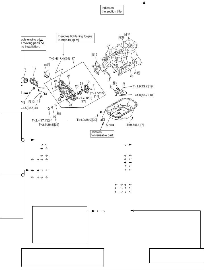
FRONT CASE AND OIL PAN
REMOVAL AND INSTALLATION
|
|
|
|
|
|
|
|
|
6EN1898 |
|
|
|
N |
1. |
Oil filter |
|
H |
17. |
Oil pump case assembly |
|
|
|
|
||||||
|
|
|
|
||||||
|
|
|
M |
2. |
Oil pressure switch |
|
|
18. |
Front case gasket |
|
|
|
|
3. |
Drain plug |
|
G |
19. |
Oil pump cover |
|
|
|
L |
4. |
Drain plug gasket |
|
G |
20. |
Oil pump drive gear |
|
|
A |
K |
5. |
Oil pan |
|
G |
21. |
Oil pump driven gear |
|
|
|
|
6. |
Oil screen |
|
F |
22. |
Crankshaft front oil seal |
|
|
|
|
7. |
Oil screen gasket |
|
E |
23. |
Oil pump oil seal |
|
|
B |
J |
8. |
Plug |
|
D |
24. |
Counterbalance shaft oil seal |
|
|
|
|
9. |
O-ring |
|
|
25. |
Front case |
|
|
|
|
|
|
||||
|
|
C |
I |
10. |
Flang bolt |
|
|
26. |
Counterbalance shaft, left |
|
|
|
|
||||||
|
|
|
|
11. Relief plug |
|
|
27. |
Counterbalance shaft, right |
|
|
|
|
|
12. |
Gasket |
D |
C |
28. |
Counterbalance shaft, front bearing |
|
|
|
|
13. |
Relief spring |
E |
B |
29. |
Counterbalance shaft, rear bearing, left |
|
|
|
|
14. |
Relief plunger |
E |
A |
30. |
Counterbalance shaft, rear bearing, right |
15.Oil filter bracket
16.Oil filter bracket gasket
|
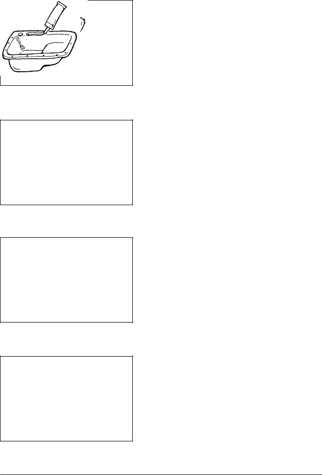
REMOVAL SERVICE POINTS |
MD998727 |
A Oil pan removal |
|
(1)Remove the all oil pan bolts.
(2)Drive in the special tool between the cylinder block and oil pan.
(3)Side the tool by striking the edge of the special tool to separate the oil pan from the cylinder block.
6EN0698
This alphabetical letter corresponds to the one assigned to a part in the removal, installation, disassembly or reassembly steps that are indicated in the drawing on the first page of each section.
Operating procedures, cautions, etc. on removal, installation, disassembly and reassembly are described
G424 Service Manual |
5 |
General Information |
SEALANT
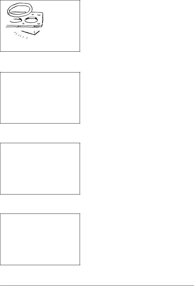
Precautions Before Servce
Removal and Disassembly
For prevention of wrong installation or reassembly and for ease of operation, put mating marks to the parts where no function is adversely affected.
1EN0018
Special Tool
Be sure to use Special Tools when their use is specified for the operation.
Use of substitute tools will result in malfunction of the part or damage it.
1EN0019
Tightening Torque
Tighten the part properly to specified torque.
1EN0020
Sealant
Use specified brand of sealant.
Use of sealant other than specified sealant may cause water or oil leaks.
1EN0021
G424 Service Manual |
6 |
General Information |
Replacement Part
When oil seal, O-ring, packing and gasket have been removed, be sure to replace them with new parts. However, rocker cover gasket may be reused if it is not damaged.
1EN0022
Rubber Parts
Do not stain timing belt and V-belt with oil or water. Therefore, do not clean the pulley and sprocket with detergent.
1EN0023
Oil and Grease
Before reassembly, apply specified oil to the rotating and sliding parts.
1EN0024
Genuine Part
When the part is to be replaced, be sure to use genuine part.
For selection of appropriate parts, refer to the Parts Catalog.
1EN0025
G424 Service Manual |
7 |
General Information |
General
Engine models and numbers
Engine model |
Fuel type |
|
|
G424 |
Gasoline, LPG, LPG (Low Emission Version) |
|
|
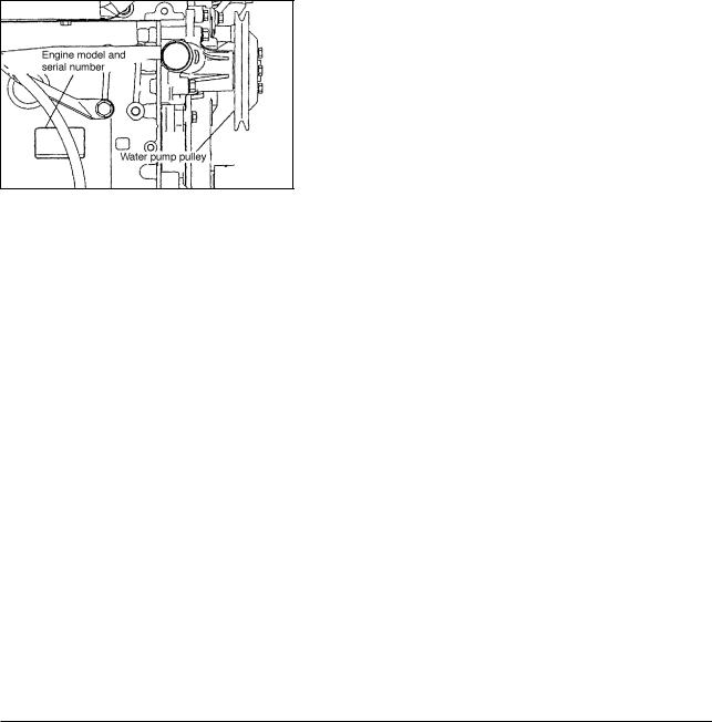
Indication of engine model and number
The engine model and serial number are stamped on the right side of cylinder block surface.
Engine model |
Engine number |
|
|
4G64 |
AA0001 to YY9999 |
|
|
6EN1916
G424 Service Manual |
8 |
General Information |

Tightening Torque
Major Bolts and Nuts
|
Item |
|
|
Torque |
|
|
Remarks |
||
|
|
|
|
|
|
|
|||
|
kg•m |
|
lb•ft |
|
N•m |
||||
|
|
|
|
|
|
||||
|
|
|
|
|
|
|
|
|
|
|
Water pump pulley bolt |
0.9 |
|
6.5 |
|
9 |
|
|
|
|
|
|
|
|
|
|
|
|
|
|
Crankshaft pulley bolt |
2.5 |
|
18.1 |
|
25 |
|
|
|
|
|
|
|
|
|
|
|
|
|
Ignition system |
Spark plug |
2.5 |
|
18.1 |
|
25 |
|
|
|
|
|
|
|
|
|
|
|
|
|
|
Distributor nut |
1.2 |
|
8.7 |
|
12 |
|
|
|
|
|
|
|
|
|
|
|
|
|
|
Timing belt cover bolt |
1.1 |
|
8.0 |
|
11 |
|
|
|
|
|
|
|
|
|
|
|
|
|
|
|
|
0.9 |
|
6.5 |
|
9 |
|
|
|
|
|
|
|
|
|
|
|
|
|
Tensioner spring spacer |
4.9 |
|
35.4 |
|
48 |
|
|
|
|
|
|
|
|
|
|
|
|
|
Tensioner belt |
Tensioner bolt |
4.9 |
|
35.4 |
|
48 |
|
|
|
|
|
|
|
|
|
|
|
|
|
|
Oil pump sprocket nut |
5.5 |
|
39.8 |
|
54 |
|
|
|
|
|
|
|
|
|
|
|
|
|
|
Crankshaft bolt |
12.0 |
|
86.8 |
|
118 |
|
|
|
|
|
|
|
|
|
|
|
|
|
|
Tensioner B bolt |
1.9 |
|
13.7 |
|
19 |
|
|
|
|
|
|
|
|
|
|
|
|
|
|
Counterbalance shaft |
4.6 |
|
33.3 |
|
45 |
|
|
|
|
|
|
|
|
|
|
|
|
|
|
Engine support bracket bolt |
3.6 |
|
26.0 |
|
35 |
|
|
|
|
|
|
|
|
|
|
|
|
|
|
Camshaft sprocket bolt |
9.0 |
|
65.1 |
|
88 |
|
|
|
|
|
|
|
|
|
|
|
|
|
|
Timing belt rear bolt |
1.4 |
|
10.1 |
|
14 |
|
|
|
|
|
|
|
|
|
|
|
|
|
Fuel system |
Carburetor nut |
1.2 |
|
8.7 |
|
12 |
|
|
|
|
|
|
|
|
|
|
|
|
|
carburetor |
Air horn nut |
1.2 |
|
8.7 |
|
12 |
|
|
|
|
|
|
|
|
|
|
|
|
|
|
Stud |
1.2 |
|
8.7 |
|
12 |
|
|
|
|
|
|
|
|
|
|
|
|
|
|
Fuel pump |
1.1 |
|
8.0 |
|
11 |
|
|
|
|
|
|
|
|
|
|
|
|
|
Fuel system |
LPG carburetor nut |
1.2 |
|
8.7 |
|
12 |
|
|
|
|
|
|
|
|
|
|
|
|
|
LPG carburetor |
Fuel pump cover |
1.1 |
|
8.0 |
|
11 |
|
|
|
|
|
|
|
|
|
|
|
|
|
Intake manifold |
Water outlet bolt |
1.4 |
|
10.1 |
|
14 |
|
|
|
|
|
|
|
|
|
|
|
|
|
|
Intake manifold bolt/nut |
1.8 |
|
13.0 |
|
18 |
|
|
|
|
|
|
|
|
|
|
|
|
|
Exhaust |
Oil level gauge guide bolt |
1.4 |
|
10.1 |
|
14 |
|
|
|
|
|
|
|
|
|
|
|
|
|
manifold |
Heat protector bolt |
0.9 |
|
6.5 |
|
9 |
|
|
|
|
|
|
|
|
|
|
|
|
|
|
Exhaust manifold nut |
3.5 |
|
25.3 |
|
34 |
|
|
|
|
|
|
|
|
|
|
|
|
|
|
Water inlet pipe bolt |
1.4 |
|
10.1 |
|
14 |
|
|
|
|
|
|
|
|
|
|
|
|
|
|
Water pump bolt |
1.4 |
|
10.1 |
|
14 |
|
|
|
|
|
|
|
|
|
|
|
|
|
Rocker arm |
Rocker cover bolt |
0.6 |
|
4.3 |
|
6 |
|
|
|
|
|
|
|
|
|
|
|
|
|
|
M8 B 25 |
2.4 |
|
17.4 |
|
24 |
|
|
|
and camshaft |
Bearing cap bolt |
|
|
|
|
||||
|
|
|
|
|
|
|
|
||
M6 B 65 |
2.0 |
|
14.5 |
|
20 |
|
|
||
|
|
|
|
|
|
||||
|
|
|
|
|
|
|
|
|
|
Cylinder head, |
|
|
8.0 kgf•m(57.9 lb•ft)[78 N•m]+ 0 + |
|
|||||
|
|
|
|
||||||
valve |
Cylinder head bolt |
2.0 kgf•m(14.5 lb•ft)[20 N•m]+ |
|
||||||
|
|
|
|
1/4 turn + 1/4 turn |
|
|
|
||
|
|
|
|
|
|
|
|
|
|
G424 Service Manual |
9 |
General Information |
|
Item |
|
Torque |
|
|
Remarks |
|
|
|
|
|
|
|||
|
kg•m |
lb•ft |
N•m |
||||
|
|
|
|
||||
|
|
|
|
|
|
|
|
|
Drain plug |
4.0 |
28.9 |
39 |
|
|
|
|
|
|
|
|
|
|
|
|
Oil pan bolt |
0.7 |
5.1 |
7 |
|
|
|
|
|
|
|
|
|
|
|
|
Oil screen bolt/nut |
1.9 |
13.7 |
19 |
|
|
|
|
|
|
|
|
|
|
|
|
Oil pressure switch |
1.0 |
7.2 |
10 |
|
|
|
|
|
|
|
|
|
|
|
Front case, |
Plug |
2.4 |
17.4 |
24 |
|
|
|
|
|
|
|
|
|
|
|
doil pan |
Flange bolt |
3.7 |
26.8 |
36 |
|
|
|
|
|
|
|
|
|
|
|
|
Relief plug |
45 |
32.5 |
44 |
|
|
|
|
|
|
|
|
|
|
|
|
Oil filter bracket |
1.9 |
13.7 |
19 |
|
|
|
|
|
|
|
|
|
|
|
|
Oil pump cover bolt |
1.7 |
12.3 |
17 |
|
|
|
|
|
|
|
|
|
|
|
|
Oil pump cover screw |
1.0 |
7.2 |
10 |
|
|
|
|
|
|
|
|
|
|
|
|
Front case bolt |
2.4 |
17.4 |
24 |
|
|
|
|
|
|
|
|
|
|
|
Piston, |
Connecting rod bearing nut |
2.0 kg•m(14.5 lb•ft) [20 N•m]+ 1/4 turn |
|
||||
connecting rod. |
|
|
|
||||
|
|
|
|
|
|
|
|
|
|
|
|
|
|
|
|
|
Flywheel bolt |
13.5 |
97.6 |
132 |
|
|
|
|
|
|
|
|
|
|
|
|
Rear plate bolt |
|
0.9 |
6.5 |
9 |
|
|
Crankshaft, |
|
|
|
|
|
|
|
|
6.0 |
43.4 |
59 |
|
|
||
|
|
|
|
||||
|
|
|
|
|
|
|
|
cylinder block |
Rear plate cover |
1.1 |
8.0 |
11 |
|
|
|
|
|
|
|
|
|
|
|
|
Oil seal case bolt |
1.1 |
8.0 |
11 |
|
|
|
|
|
|
|
|
|
||
|
Bearing cap bolt |
2.0 kg•m(14.5 lb•ft) [20 N•m]+ 1/4 turn |
|
||||
|
|
|
|
|
|
|
|
Starter motor |
Starter motor bolt |
2.7 |
19.5 |
26 |
|
|
|
G424 Service Manual |
10 |
General Information |

General Bolts and Nuts Tightening Torque
Standard Bolts and Nuts
|
|
|
Torque, kg•m (lb•ft) [N•m] |
|
|||
Nominal |
|
|
|
|
|
|
|
Pitch |
Bolt, stud, nut (with spring washer) |
Flange bolt, flange nut |
|||||
diameter |
|||||||
|
|
|
|
|
|
||
|
Head mark 4 |
Head mark 7 |
Head mark 10 |
Head mark 4 |
Head mark 7 |
||
|
|
||||||
|
|
|
|
|
|
|
|
M5 |
M5 |
- |
0.5 (0.5) [3.6] |
- |
- |
0.6 (4.3) [5.9] |
|
|
|
|
|
|
|
|
|
M6 |
M6 |
- |
0.9 (6.5) [8.8] |
1.2 (8.7) [12] |
- |
1.0 (7.2) [9.8] |
|
|
|
|
|
|
|
|
|
M7 |
M7 |
1.2 (8.7) [12] |
2.2 (15.9) [22] |
3.0 (21.7) [29] |
1.3 (9.4) [13] |
2.4 (17.4) [24] |
|
|
|
|
|
|
|
|
|
M8 |
M8 |
2.5 (18.1) [25] |
4.5 (32.5) [44] |
6.0 (43.4) [59] |
2.6 (18.8) [25] |
5.0 (36.2) [49] |
|
|
|
|
|
|
|
|
|
M9 |
M9 |
4.2 (30.4) [41] |
8.6 (60.0) [81] |
10.7 (77.4) [105] |
4.7 (34.0) [46] |
9.5 (68.7) [93] |
|
|
|
|
|
|
|
|
|
M10 |
M10 |
7.3 (52.8) [72] |
14.0 (101.3) [137] |
14.5 (104.9) [142] |
- |
- |
|
|
|
|
|
|
|
|
|
Tapered Threads
|
Torque, kg•m (lb•ft) [N•m] |
||
|
|
|
|
Size |
Material of internal threads: |
Material of internal threads: |
|
|
Aluminum alloy |
Cast iron or steel |
|
|
|
|
|
NPTF 1/16 |
0.5 to 0.8 (3.6 to 5.8) |
[5 to 8] |
0.8 to 1.2 (5.8 to 8.7) [8 to 11] |
|
|
|
|
PT 1/8 |
0.8 to 1.2 (5.8 to 8.7) [8 to 11] |
1.5 to 2.2 (10.8 to 15.9) [15 to 21] |
|
|
|
|
|
PT 1/4 |
2.0 to 3.0 (14.5 to 21.7) |
[20 to 29] |
3.5 to 4.5 (25.3 to 32.5) [34 to 44] |
|
|
|
|
NPTF 1/4 |
2.0 to 3.0 (14.5 to 21.7) |
[20 to 29] |
3.5 to 4.5 (25.3 to 32.5) [34 to 44] |
|
|
|
|
PT 3/8 |
4.0 to 5.5 (28.9 to 39.8) |
[39 to 59] |
5.5 to 7.5 (39.8 to 54.2) [54 to 73] |
|
|
|
|
PT 1/2 |
7.0 to 10.0 (50.6 to 72.3) [69 to 98] |
12.0 to 16.0 (86.8 to 115.7) [118 to 156] |
|
|
|
|
|
New Tightening Method-By Use of Bolts to be Tightened in Plastic Area
A new type of bolts, to be tightened in plastic area, is currently used in some parts of the engine. The tightening method for the bolts is different from the conventional one. Be sure to observe the method described in the text when tightening the bolts.
Service limits are provided for the bolts. Make sure that the service limits described in the text are strictly observed.
•Area where the bolts are in use:
(1)Cylinder head bolts
(2)Main bearing cap bolts
(3)Connecting rod cap bolts
•Tightening method
After tightening the bolts to the specified torque, tighten them another 90° or 180° (twice 90°). The tightening method varies on different areas. Observe the tightening method described in the text.
G424 Service Manual |
11 |
General Information |

Sealant
Part to be Applied |
Brand |
|
|
Semi circular packing |
3MTM AAD Part No.8672 or equivalent |
|
|
Rocker cover |
3MTM AAD Part No.8672 or equivalent |
Oil pressure switch |
3MTM AAD Part No.8672 or equivalent |
|
|
Oil pan |
Silicone RTV sealant or eguivalent |
|
|
Rear oil seal case |
Silicone RTV sealant or eguivalent |
|
|
Rear plate bolt |
3MTM AAD Part No.8672 or equivalent |
|
|
Oil seal case bolt |
3MTM AAD Part No.8672 or equivalent |
|
|
From in Place Gasket (FIPG)
The engine has several areas where the from-in-place gasket(FIPG) is in use. To ensure that gasket fully serves its purpose, it is necessary to observe some precautions when applying the gasket. Bead size, continuity and location are of paramount importance. Too thin a bead could cause leaks. Too thick a bead, on the other hand, could be squeezed out of location, causing blocking or narrowing of the fluid feed line. To eliminate the possibility of leaks from a joint, therefore, it is absolutely necessary to apply the gasket evenly without a break, while observing the correct bead size.
Since the FIPG used in the engine hardens as it reacts with the moisture in the atmospheric air, it is normally used in the metallic flange areas.
Disassembly
The parts assembled with the FIPG can be easily disassembled without use of a special method. In some cases, however, the sealant between the joined surfaces may have broken by lightly striking with a mallet or similar tool. A flat and thin gasket scraper may be lightly hammered in between the joined surfaces. In this case, however, care must be taken to prevent damage to the joined surfaces. For removal of the oil pan, the special tool “Oil Pan Remover” (MD998727) is available. Be sure to use the special tool to remove the oil pan.
Surface preparation
Thoroughly remove all substances deposited on the gasket application surfaces, using a gasket scraper or wire brush.
Check to ensure that the surfaces to which the FIPG is to be applied is flat. Make sure that there are no oils, greases and foreign substances deposited on the application surfaces. Do not forget to remove the old FIPG remaining in the bolt holes.
From-in-place gasket Application
Applied FIPG bead should be of the specified size and without breaks. Also be sure to encircle the bolt hole circumference with a completely continuous bead. The FIPG can be wiped away unless it is hardened. While the FIPG is still moist (in less than 15 minutes), mount the parts in position. When the parts are mounted, make sure that the gasket is applied to the required area only.
The FIPG application procedure may vary on different areas. Observe the procedure described in the text when applying the FIPG.
G424 Service Manual |
12 |
General Information |

SPECIFICATIONS
General Specifications
Item |
Engine model |
G424 |
||
|
|
|
||
|
|
|
|
|
|
|
|
|
|
Type |
|
|
|
Water-cooled, 4-cycle, gasoline-powered and L.P.G.-powered |
|
|
|
|
|
No. of cylinders and arrangement |
|
4, in-line |
||
|
|
|
|
|
Combustion chamber type |
|
Semi-spherical |
||
|
|
|
|
|
Valve mechanism |
|
|
|
OHC |
|
|
|
|
|
Total displacement, cm3(cc) [cu in.] |
|
2350 (2350) [143] |
||
Bore x stroke, mm (in.) |
|
86.5 B 100 (3.41 B 3.94) |
||
|
|
|
|
|
Dry weight, kg (lb) |
|
|
|
146 (322) |
|
|
|
|
|
Compression ratio |
|
|
|
8.6 |
|
|
|
|
|
Compression pressure, kPa (kgf/cm2) [psi] |
1128 (11.5) [163.5] |
|||
|
Intake |
|
Open |
12° BTDC |
|
|
|
|
|
Valve timing |
valve |
|
Close |
40° ABDC |
|
|
|
|
|
Exhaust |
|
Open |
54° BBDC |
|
|
|
|||
|
|
|
|
|
|
valve |
|
Close |
6° ATDC |
|
|
|
|
|
Firing order |
|
|
|
1 - 3 - 4 - 2 |
|
|
|
|
|
Ignition timing, BTDC/rpm |
|
4°/740 (gasoline), 9°/740 (L.P.G.), 4˚/740(dual fuel) |
||
|
|
|
|
|
Fuel pump |
|
|
Gasoline |
Mechanical (diaphragm type) |
|
|
|
|
|
Carburetor |
|
|
|
Down-draft type |
|
|
|
|
|
Governor |
|
|
|
Air flow type |
|
|
|
|
|
Lubrication system |
|
|
|
Pressure feed, full-flow filtration type |
|
|
|
|
|
Oil pump |
|
|
|
Gear, driven by timing belt |
|
|
|
|
|
Oil filter |
|
|
|
Filter paper, cartridge type |
|
|
|
|
|
Cooling system |
|
|
|
Water-cooled, forced circulation |
|
|
|
|
|
Water pump |
|
|
|
Centrifugal, driven by V-belt |
|
|
|
|
|
Thermostat |
|
|
|
Wax type |
|
|
|
|
|
Electrical system |
|
|
|
12V DC, negative ground |
|
|
|
|
|
Alternator, (12V-61A) |
|
|
|
Alternator current, built-in fan and regulator |
|
|
|
|
|
Starter motor, (12V-1.2kW) |
|
Reduction drive |
||
|
|
|
|
|
Distributor |
|
|
|
Equipped with automatic timing controller, breaker less type |
|
|
|
|
|
Spark plug (NGK) |
|
|
Gasoline |
BPR4ES |
|
|
|
|
|
|
|
|
L. P. G. |
BPR5ES |
|
|
|
|
|
Quantity of lubricating oil, cm3 (liter) [U.S.gal] |
4000(4.0) [1.06 ]( including 300 cm3(0.3 liter)[0.08 U.S.gal ]in oil filter |
|||
Quantity of coolant, cm3 (liter) [U.S.gal] |
3100 (3.1) [0.82] (in engine proper) |
|||
IDLE RPM |
LOW (RPM) |
|
700 L 25 |
|
|
|
|
|
|
|
HIGH (RPM) |
|
2700 L 50 |
|
|
|
|
|
|
G424 Service Manual |
13 |
Specifications |

Service Specifications
|
|
|
|
|
|
|
|
Unit : mm(in.) |
|
|
|
|
|
|
|
|
|
|
|
|
Item |
|
Standard value |
Limit |
Remarks |
|
|
|
|
|
|
|
|
|
|
|
Flatness of gasket surface |
|
0.03 |
(0.0012) |
|
|
||
|
|
|
|
|
|
|
|
|
|
|
|
|
|
|
|
|
Total resurfacing |
|
Grinding limit |
|
|
|
|
0.2 (0.008) |
depth of both |
|
|
|
|
|
|
cylinder head and |
|||
|
|
|
|
|
|
|
|
cylinder block |
head |
|
|
|
|
|
|
|
|
Overall height |
|
|
89.9 to 90.1 |
(3.539 to 3.547) |
|
|
||
|
|
|
|
|
||||
|
|
|
|
|
|
|
|
|
Cylinder |
Oversize rework |
0.05 (0.0020) |
13.05 to 13.07 |
(0.5138 to 0.5146) |
|
|
||
dimensions of valve |
0.25 (0.0098) |
13.25 to 13.27 |
(0.5217 to 0.5224) |
|
|
|||
|
|
|
||||||
|
guide hole |
|
|
|
|
|
|
|
|
|
0.50 (0.0197) |
13.50 to 13.57 |
(0.5315 to 0.5343) |
|
|
||
|
|
|
|
|
|
|
|
|
|
Oversize |
|
Intake |
0.30 (0.0118) |
47.30 to 47.33 |
(1.8622 to 1.8634) |
|
|
|
rework |
|
|
|
|
|
|
|
|
|
0.60 (0.0236) |
47.60 to 47.63 |
(1.8740 to 1.8752) |
|
|
||
|
dimensions of |
|
|
|
|
|||
|
|
|
|
|
|
|
|
|
|
|
Exhaust |
0.30 (0.0118) |
40.30 to 40.33 |
(1.5866 to 1.5878) |
|
|
|
|
valve seat |
|
|
|
||||
|
ring hole |
|
|
0.60 (0.0236) |
40.60 to 40.63 |
(1.5984 to 1.5996) |
|
|
|
|
|
|
|
|
|
|
|
Camshaft |
Cam height |
|
Intake |
41.62 (1.6386) |
41.12 (1.6189) |
|
||
|
|
|
|
|
|
|||
|
|
Exhaust |
41.62 (1.6386) |
41.12 (1.6189) |
|
|||
|
|
|
|
|
||||
|
|
|
|
|
|
|
||
|
Journal diameter |
|
33.935 to 33.950 (1.33602 to 1.33661) |
|
|
|||
|
|
|
|
|
|
|
|
|
|
Oil clearance |
|
|
0.05 to 0.09 (0.0020 to 0.0035) |
|
|
||
|
|
|
|
|
|
|
|
|
|
Overall length |
|
Intake |
106.6 (4.197) |
106.1 (4.126) |
|
||
|
|
|
|
|
|
|
||
|
|
Exhaust |
105.2 (4.142) |
104.7 (4.122) |
|
|||
|
|
|
|
|
||||
|
|
|
|
|
|
|
||
|
Valve stem projection |
|
42.05 (1.6555) |
42.55 (1.6752) |
|
|||
|
|
|
|
|
|
|
|
|
|
Stem diameter |
|
Intake |
7.960 to 7.975 (0.31339 to 0.31398) |
|
|
||
|
|
|
|
|
|
|
|
|
Valve |
|
|
|
Exhaust |
7.930 to 7.950 (0.31220 to 0.31299) |
|
|
|
|
|
|
|
|
|
|
||
Face angle |
|
|
45° to 45.5° |
|
|
|||
|
|
|
|
|
|
|
|
|
|
Thickness of valve |
Intake |
1.2 |
(0.047) |
|
|
||
|
|
|
|
|
|
|
|
|
|
head (margin) |
|
Exhaust |
2.0 |
(0.079) |
|
|
|
|
|
|
|
|
|
|
|
|
|
Stem-to-guide |
|
Intake |
0.025 to 0.058 (0.00098 to 0.00228) |
|
|
||
|
|
|
|
|
|
|
|
|
|
clearance |
|
Exhaust |
0.050 to 0.088 (0.00197 to 0.00346) |
|
|
||
|
|
|
|
|
|
|
|
|
spring |
Free height |
|
|
48.0 (1.89) |
47.0 (1.85) |
|
||
|
|
|
|
|||||
|
|
|
|
|
|
|
||
Valve |
Load/installed height |
|
176.5N (18kg) [39.7lbf]/40.4 (1.591) |
|
|
|||
|
|
|
|
|
|
|||
Out-of-squareness |
|
2° or less |
4° |
|
||||
|
|
|
|
|
|
|
|
|
guide |
Overall length |
|
Intake |
47 (1.85) |
|
|
||
|
|
|
|
|
|
|||
|
Exhaust |
52 (2.05) |
|
|
||||
Valve |
|
|
|
|
|
|||
|
|
|
|
|
|
|
||
Inner diameter |
|
|
8.000 to 8.018 (0.31496 to 0.31567) |
|
|
|||
|
|
|
|
|
|
|
||
seat |
Valve contact width |
|
0.9 to 1.3 (0.035 to 0.051) |
|
|
|||
Valve |
|
|
|
|
|
|
|
|
Sinkage |
|
|
|
|
0.2 (0.008) |
|
||
|
|
|
|
|
|
|
|
|
Piston |
Outside diameter |
|
86.47 to 86.50 |
(3.4043 to 3.4055) |
|
|
||
|
|
|
|
|
|
|||
Piston clearance |
|
0.02 to 0.04 (0.0008 to 0.0016) |
|
|
||||
G424 Service Manual |
14 |
Specifications |

|
|
|
|
|
|
|
Unit : mm(in.) |
|
|
|
|
|
|
|
|
|
Item |
|
Standard value |
Limit |
Remarks |
||
|
|
|
|
|
|
|
|
ring |
End gap |
|
No. 1 ring |
0.25 to 0.40 (0.0098 to 0.0157) |
0.8 (0.031) |
|
|
|
|
|
|
|
|
|
|
|
|
|
No. 2 ring |
0.45 to 0.60 (0.0177 to 0.0236) |
0.8 (0.031) |
|
|
|
|
|
|
|
|||
|
|
|
|
|
|
|
|
Piston |
|
|
|
Oil ring |
0.20 to 0.60 (0.0079 to 0.0236) |
1.0 (0.039) |
|
|
|
|
|
|
|
|
|
Ring-to-ring groove |
|
No. 1 |
0.03 to 0.07 (0.0012 to 0.0028) |
|
|
||
|
|
|
|
||||
|
|
|
|
|
|
|
|
|
clearance |
|
No. 2 |
0.03 to 0.07 (0.0012 to 0.0028) |
|
|
|
|
|
|
|
|
|
|
|
pin |
Outside diameter |
|
22.002 to 22.005 (0.86622 to 0.86634) |
|
|
||
|
|
|
|
|
|
|
|
Press-in load |
|
7350 to 17160 |
|
|
|||
Piston |
|
|
|
||||
(at room temperature), |
|
(750 to 1750) |
|
|
|||
|
|
|
|
||||
|
N (kg) [lbf] |
|
[1650 to 3860] |
|
|
||
|
|
|
|
|
|
||
rod |
Big end center-to small end center |
149.9 to 150.0 (5.902 to 5.906) |
|
|
|||
length |
|
|
|
|
|||
Connecting |
|
|
|
|
|||
|
|
|
|
|
|
||
Big end thrust clearance |
|
0.10 to 0.25 (0.0039 to 0.0098) |
|
|
|||
|
Bend |
|
0.05 (0.0020) |
|
|
||
|
Twist |
|
0.10 (0.0039) |
|
|
||
|
|
|
|
|
|
|
|
|
End play |
|
0.05 to 0.18 (0.0020 to 0.0071) |
|
|
||
|
|
|
|
|
|
|
|
|
Journal outside diameter |
|
56.982 to 57.000 (2.24338 to 2.24409) |
|
|
||
|
|
|
|
|
|
|
|
Crankshaft |
Pin Outside diameter |
|
44.985 to 45.000 (1.77106 to 1.77165) |
|
|
||
|
|
|
|
|
|
|
|
Out-of-roundness and taper of |
0.005 (0.00020) |
|
|
||||
|
|
|
|||||
|
journal and pin |
|
|
|
|||
|
|
|
|
|
|||
|
|
|
|
|
|
||
|
Concentricity journal and pin |
0.03 (0.0012) |
|
|
|||
|
Oil clearance of journal |
|
0.02 to 0.04 (0.0008 to 0.0016) |
|
|
||
|
Oil clearance of pin |
|
0.02 to 0.05 (0.0008 to 0.0020) |
|
|
||
block |
Cylinder inner diameter |
|
86.50 to 86.53 (3.4055 to 3.4067) |
|
|
||
Flatness of gasket surface |
|
0.05 (0.0020) |
|
|
|||
|
|
|
|
||||
Cylinder |
|
|
|
|
|
|
Total resurfacing |
Grinding limit |
|
|
0.2 (0.008) |
depth of both |
|||
|
|
|
|||||
|
|
|
cylinder head and |
||||
|
|
|
|
|
|
|
|
|
|
|
|
|
|
|
cylinder block |
|
Overall height |
|
289.9 to 290.1 (11.413 to 11.421) |
|
|
||
Oil pump |
Side clearance |
|
|
Drive gear |
0.08 to 0.14 (0.031 to 0.0055) |
|
|
|
|
Drive gear |
0.06 to 0.12 (0.0024 to 0.0047) |
|
|
||
|
|
|
|
|
|||
Drive belt |
Deflection |
|
|
New belt |
7.0 to 10.0 (0.28 to 0.39) |
|
|
|
|
Used belt |
10 (0.39) |
|
|
||
|
|
|
|
|
|
|
|
|
|
|
|
|
|
|
|
|
Throttle bore diameter |
|
32 (1.26) |
|
|
||
|
Outer venturi diameter |
|
24 (0.94) |
|
|
||
Carburetor |
Inner venturi diameter |
|
9 to 12 (0.35 to 0.47) |
|
|
||
|
|
|
|
||||
|
Main jet (Symbol Size) |
|
132.5 |
|
|
||
|
Main air jet diameter |
|
0.9 (0.035) |
|
|
||
|
Pilot jet diameter |
|
0.55 (0.0217) |
|
|
||
|
Pilot air jet diameter |
|
1.6 (0.063) |
|
|
||
|
Primary throtle valve to throtle |
1.1(0.043) |
|
|
|||
|
bore clearance |
|
|
|
|
||
G424 Service Manual |
15 |
Specifications |

|
|
|
|
|
|
|
|
Unit : mm(in.) |
|
|
|
|
|
|
|
|
|
|
Item |
|
|
Standard value |
Limit |
Remarks |
||
|
|
|
|
|
|
|
|
|
|
Nominal output, kW |
|
|
1.2 |
|
|
||
|
|
|
|
|
|
|
|
|
|
|
|
|
Voltage, V |
11.0 |
|
|
|
|
|
|
|
|
|
|
|
|
motor |
No-load characterstics |
|
Current, A |
90 or less |
|
|
||
|
|
|
|
|
|
|
|
|
|
|
|
Speed, rpm |
3000 |
|
|
||
|
|
|
|
|
|
|||
|
|
|
|
|
|
|
|
|
Starter |
|
|
|
Outer diameter |
29.4 (1.16) |
28.8 (1.13) |
|
|
|
|
|
|
|
|
|
|
|
Commutator |
|
Runout |
0.05 (0.0020) |
0.1 (0.0039) |
|
|||
|
|
|
||||||
|
|
|
|
|
|
|
|
|
|
|
|
|
Undercut |
0.5 (0.020) |
0.2 (0.008) |
|
|
|
|
|
|
|
|
|
|
|
|
Pinion gap |
|
|
0.5 to 2.0 (0.020 to 0.079) |
|
|
||
|
|
|
|
|
|
|
|
|
|
Brush length |
|
|
|
Wear limit line |
|
||
|
|
|
|
|
|
|
|
|
Distributor |
Centrifugal advance crank |
|
Start |
0°/1000 |
|
|
||
angle/engine speed, °/rpm |
|
|
|
|
|
|||
|
End |
20°/5000 |
|
|
||||
|
|
|
|
|||||
|
|
|
|
|
|
|
|
|
|
Vacuum advance crank |
|
End |
0°/80 |
|
|
||
|
angle/vacuum, °/mmHg |
|
|
|
|
|
||
|
|
Start |
23°/280 |
|
|
|||
|
|
|
|
|
|
|
|
|
n coil |
Primary coil resistance, Ω |
|
|
1.08 to 1.32 |
|
|
||
Ignitio |
|
|
|
|
|
|
|
|
Secondary coil resistance, Ω |
22.1 to 29.9 |
|
|
|||||
plug |
Plug gap |
|
|
0.7 to 0.8 (0.028 to 0.031) |
|
|
||
Spark |
|
|
|
|
||||
|
|
|
|
|
|
|
|
|
Tahermostat |
Valve lift |
|
|
8 (0.31) or more |
|
|
||
|
Valve opening temperature, °C (˚F) |
82 (180) |
|
|
||||
|
Fully opening temperature, ˚C (˚F) |
95 (203) |
|
|
||||
|
|
|
|
|
|
|
|
|
|
Oil Pressure |
|
|
Low Idle |
50 kPa(7psi) |
|
|
|
|
|
|
|
|
|
|
|
|
|
|
|
High Idle |
450 kPa(65psi) |
|
|
||
|
|
|
|
|
|
|||
|
|
|
|
|
|
|
|
|
|
|
|
|
|
|
|
|
|
G424 Service Manual |
16 |
Specifications |
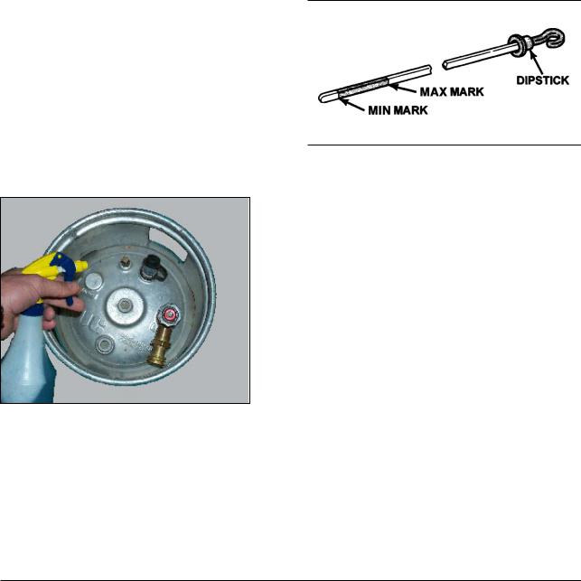
MAINTENANCE
G424 engine requires a certain amount of maintenance. Suggested maintenance requirements are contained in this section. The owner should, however, develop his own maintenance schedule using the requirements listed in this section and any other necessary requirements resulting from optional additions to the engine system.
Test Fuel System for Leaks
•Obtain a pump spray bottle.
•Fill with an approved leak test solution or a mixture of water and dish soap.
•Spray a generous amount of the solution on the entire fuel system including the fuel storage container and fuel lines.
•Wait approximately 15-60 seconds then perform a visual inspection of entire fuel system.
•Leaks will cause the soapy solution to bubble.
•Repair any leaks before continuing.
•Crank the engine through several revolutions. This will energize the fuel lock and allow fuel to flow to the pressure regulator/vaporizer. Apply additional leak test solution to this portion of the fuel system and inspect as above.
•Repair any fuel leaks before continuing.
1.Stop engine if in use.
2.Allow sufficient time (approximately 2 minutes) for the oil to drain back into the oil pan.
3.Remove dipstick. Wipe clean and reinstall. Push dipstick all the way into the dipstick tube.
4.Remove dipstick and note the oil level.
5.Oil level must be between the "MAX" and "MIN" marks.
6.If the oil level is below the "MIN" mark, proceed to Steps 7 and 8, and reinstall dipstick into the dipstick tube.
7.Remove oil filler cap from the valve rocker arm cover.
8.Add required amount of oil to bring level up to, but not over, the "MAX" mark on dipstick.
NOTE: When refill engine oil, refill same oil as that used before.
Check Engine Oil Level
IMPORTANT : Care must be taken when checking
engine oil level. Oil level must be main-tained between
the "MIN" mark and the "MAX" mark on the dipstick. To
ensure that you are not getting a false reading, make
sure the following steps are taken before checking the
oil level.
Inspect Engine for Fluid Leaks
•Start engine and bring up to operating temperature.
•Turn engine off.
•Inspect entire engine for oil and/or coolant leaks.
•Repair any/all leaks before continuing.
Change Engine Oil &Filter
•Start engine.
•Bring up to operating temperature.
•Shut down engine.
•Remove oil fill cap located in valve cover.
•Place drain pan under engine oil pan.
•Remove oil drain plug located at bottom of oil pan and allow engine oil to drain.
CAUTION : OIL WILL BE HOT.
•Remove engine oil filter. Make sure the oil filter gasket does not stick to engine.
CAUTION : OIL WILL BE HOT.
•Using a clean shop towel clean the engine oil filter gasket mating surface.
•Fill oil filter with engine oil.
G424 Service Manual |
17 |
Maintenance |

•Lube oil filter gasket with engine oil.
•Install oil filter as per filter manufacturers instructions. DO NOT OVER TIGHTEN
•Fill crankcase with engine oil.
•Start engine & run approximately 60 seconds.
•Shut down engine, wait approximately 2 - 5 minutes and then check oil level.
•When oil level is satisfactory start engine and check for any possible leaks.
•Repair any/all leaks before returning unit to service.
NOTE
Engine Oil Specification : See, Lubrication System section
Inspect Accessory Drive Belts
See, "Testing & Adjusting" of Cooling System Section.
Inspect electrical system
•Clean battery outer surfaces with a mixture of baking soda and water.
•Inspect battery outer surfaces for damage. Replace as required.
•Remove battery cables and clean.
•Inspect battery cables for worn or missing insulation, frayed wire and/or corrosion. Replace as required.
Inspect Vacuum Lines and Fittings
•Visually inspect vacuum lines and fittings for physical damage such as brittleness, cracks, kinks and misrouting. Repair/replace as required.
•Solvent damage may cause vacuum lines to become soft. Vacuum lines damaged by oil and/or other solvents may collapse when the engine is running effectively closing the passage inside the line.
Check Coolant Level
•Engine must be off and cold.
•NEVER REMOVE THE PRESSURE CAP ON A HOT ENGINE.
•The coolant level should be equal to the "COLD" mark on the coolant recovery tank. Periodically remove the cooling system pressure cap and check coolant level inside system. The coolant level should be equal to the sealing surface of the pressure cap. If level is low replace pressure cap and repair any/all other leaks.
•On closed systems visually inspect the coolant recovery tank and hoses for physical damage
•On open systems carefully remove cooling system pressure cap. Coolant level will be approximately 3040 mm below pressure cap sealing surface. If level is low replace pressure cap and repair any/all other leaks.
Inspect Coolant Hoses
•Visually inspect coolant hoses and clamps.
•Replace any hose that shows signs of swelling, cracking, abrasion hardening or any other damage/deterioration.
•Top-up cooling system with approved coolant.
Inspect Ignition System
•Remove and inspect spark plugs. Replace as required.
•Test secondary wires with an Ohmmeter. Maximum resistance repair replace as required.
•Remove distributor cap and perform visual inspection of distributor cap and rotor. Replace cap & rotor if corrosion is found on contacts.
•Inspect distributor breaker unit and housing for signs of corrosion. Repair replace as required.
Replace Spark Plugs
•Utilizing a gentle twisting motion remove the secondary high voltage leads from the spark plugs. Replace any damaged leads.
•Remove the spark plugs.
•Gap new spark plugs to proper specs.
•Apply anti-seize compound to spark plug threads.
•Install spark plugs.
•Do not over tighten.
•Install secondary high voltage leads.
G424 Service Manual |
18 |
Maintenance |
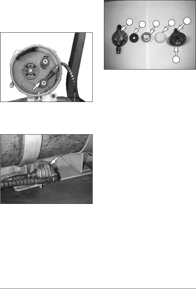
Replace LP Fuel Filter Element
Park the lift truck in an authorized refueling area with the forks lowered, parking beake applled and the transmission in NEUTRAL.
1.Close the fuel shutoff valve on the LP-Gas tank. Run the engine until fuel in the line runs out and the engine stops. Turn off the ignition switch and disconnect switch (if equipped).
2. Scribe a line across the filter housing covers.
3.Remove the cover retaining screws.
5 |
3 |
2 |
1 |
4 |
|
6
4.Remove cover (5), magnet (4), spring (3) and filter element (2) from bottom cover (1).
5.Replace the filter element (2).
6.Check bottom cover O-ring seal (6) for damage. Replace it if necessary.
7.Install the filter element (2), spring (3), magnet
(4)and cover (5) on bottom cover (1). Align the scribe line on the covers.
8.Install the cover retaining screws. Tighten the screws in a sequence opposite each other.
9.Open the fuel valve by slowly turning the valve counterclockwise.
10.Crank the engine only enough to produce a vacuum at the fuelock. Turn the ignition key switch off.
11.Check the fuel lines and fittings for leaks with a soap solution. Make repairs if necessary.
Test Fuel Lock (Electric)
•Start engine.
•Locate electrical connector for fuel lock.
•Disconnect electrical connector.
•Engine will run out of fuel and stop in a short period of time. (The length of time increases with any increase in distance between the fuel lock and the pressure regulator).
G424 Service Manual |
19 |
Maintenance |
Replace Gasoline Fuel Filter
(Gasoline Truck and Dual
Fuel Truck)
 WARNING
Fuel leaked or spilled onto hot surfaces or electrical components can cause a fire.
Turn the disconnect switch OFF if fitted or disconnect the battery when changing fuel filters
1 3
3
 2
2
1. Raise the hood and seat assembly.
2. Loosen Bolt(1) and clamps(2)(3).
3. Replace old fuel filter with new filter.
4. Fasten Bolt(1) and clamps(2)(3).
Inspect Gasoline Carburetor
See, gasoline carburetor in Gasoline fuel system section.
Inspect Pressure
Regulator/Vaporizer
See, pressure regulator/vaporizer in LP fuel system section.
Inspect LP Mixer
(Standard LP Truck)
See, LP mixer in LP fuel system section.
Inspect Variable Venturi
Air/Fuel Mixer
(Low Emission LP Truck)
See, Variable Venturi Air/Fuel Mixer in LP fuel system(Low emission version) section.
Inspect Complete Exhaust System for Leaks, Damage
•Perform visual inspection of exhaust system.
•Repair any/all leaks found.
Engine Control Unit(ECU) and others
(Low Emission LP Truck)
The commander, oxygen sensor and vacuum control solenoid are not serviceable. If faulty, they must be replaced. See Trouble Shooting Section
G424 Service Manual |
20 |
Maintenance |

Maintenance Schedule
|
|
|
Interval Hours |
|
|
||
|
|
Every |
Every |
Every |
Every |
Every |
|
CHECK POINT |
Daily |
250hrs |
500hrs |
1000hrs |
2000hrs |
1000hrs |
|
or |
or |
or |
or |
or |
|||
|
|
||||||
|
|
a month |
3 months |
6 months |
a year |
18 months |
|
|
|
|
|
|
|
|
|
General Maintenance Section |
|
|
|
|
|
|
|
Test fuel system for leaks |
Prior to any service of maintenance activity |
|
|||||
Inspect engine for fluid leaks |
O |
|
|
|
|
|
|
Check engine oil and filter |
O |
|
|
|
|
|
|
Change engine oil and filter |
|
O |
|
|
|
|
|
Inspect accessory drive belts |
|
|
|
O |
|
|
|
Inspect electrical system |
|
|
|
|
O |
|
|
Inspect all vacuum lines and fittings |
|
|
|
|
O |
|
|
Inspect all fuel fittings and hoses |
|
|
|
|
O |
|
|
Replace timing belt and counter balance shaft belt. |
|
|
|
|
|
O |
|
Check engine compression pressure |
|
|
|
|
|
O |
|
Engine Coolant Section |
|
|
|
|
|
|
|
Check coolant level |
O |
|
|
|
|
|
|
Change coolant |
|
|
|
|
O |
|
|
Inspect coolant hoses for leaks, cracks swelling, or deterioration |
|
|
|
O |
|
|
|
Engine Ignition Section |
|
|
|
|
|
|
|
Inspect battery for case damage and corroded Cables |
|
|
|
|
O |
|
|
Inspect ignition system |
|
|
|
O |
|
|
|
Check ignition timing-adjust as necessary |
|
|
|
|
O |
|
|
Replace spark plugs |
|
|
|
|
O |
|
|
Fuel Lock-Off/Filter Section |
|
|
|
|
|
|
|
Replace LP fuel filter element |
|
|
|
O |
|
|
|
Replce gasoline fuel filter |
|
|
|
|
O |
|
|
Inspect lock-off and filter for fuel leaks |
|
|
|
|
O |
|
|
Ensure lock-off stops fuel flow when engine is off |
|
|
|
|
O |
|
|
Pressure Regulator Section |
|
|
|
|
|
|
|
Test regulator pressures |
|
|
|
|
O |
|
|
Inspect pressure regulator for oil build-up |
|
|
|
|
O |
|
|
Inspect pressure regulator assembly for fuel/coolant leaks |
|
|
|
|
O |
|
|
Carburetor Section |
|
|
|
|
|
|
|
Check for air leaks in filter system |
|
|
|
|
O |
|
|
Check for vacuum leaks on complete intake system |
|
|
|
|
O |
|
|
Inspect air/gas valve assembly |
|
|
O |
|
|
|
|
Inspect air/fuel mixture throat |
|
|
O |
|
|
|
|
Inspect gasoline carburetor |
|
|
|
O |
|
|
|
Check air cleaner indicator |
O |
|
|
|
|
|
|
Inspect air cleaner |
|
O |
|
|
|
|
|
Replace air filter element |
|
|
|
|
O |
|
|
Engine Exhaust Section (Low Emission Version only) |
|
|
|
|
|
|
|
Inspect exhaust manifold for leaks |
|
|
|
|
O |
|
|
Inspect manifold-to-catalyst exhaust piping and Connections for leaks |
|
|
|
|
O |
|
|
Inspect catalyst inlet and outlet and leaks |
|
|
|
|
O |
|
|
G424 Service Manual |
21 |
Maintenance |

ENGINE SYSTEM
Engine Overview
The cylinder blocks are made of the special cast iron and employ 5-bearing, deep skirt system.
The cylinder heads have hemisphere combustion chambers, are of cross flow type arranged with V-type valves and high efficient combustion is intended.
The camshaft is located on the top of the cylinder heads and driven by cog type timing belt.
Dual type exhaust manifold is employed in order to reduce output loss by exhaust interference.
G424 Service Manual |
22 |
Engine System |
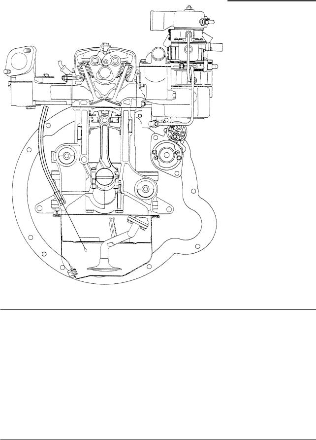
Gasoline Engine
G424 Service Manual |
23 |
Engine System |

LPG Engine ( Low Emission Version)
G424 Service Manual |
24 |
Engine System |
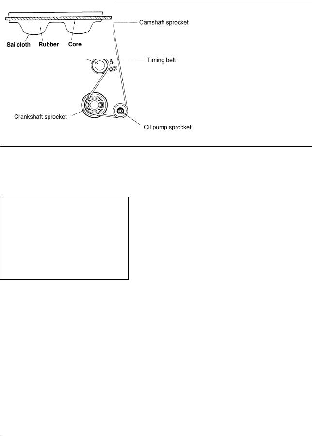
Timing System
The timing belt is meshed with the sprockets, the crankshaft sprocket becomes the drive sprocket, and thus functions to drive the camshaft and oil pump.
Timing belt
The timing belt is the cogged type, using rubber as its basic material, and it employs a high-strength glass fiber core which does not expand or contract.
The features of the cogged-type belt compared to a chin are no expansion/contraction, low noise level, no necessity for lubrication, light weight, etc.
G424 Service Manual |
25 |
Engine System |
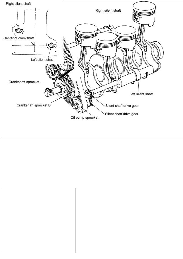
Silent Shaft Mechanism
The silent shaft mechanism function mainly to eliminate, by the action of the silent shafts incorporated at both sides of the cylinder block, the vertical vibromotive force of the engine as well as the vibromotive moment in the rolling direction, thus making possible quieter operation of the vehicle.
The two silent shafts are arranged as shown in the
figure below. The right silent shaft rotates in the same direction as the crankshaft, and the left silent shaft rotates in the opposites direction. Both of these silent shafts rotate at speed twice that of the crankshaft.
Right silent shaft is driven by timing belt B, and the left silent shaft is driven by drive gear.
G424 Service Manual |
26 |
Engine System |
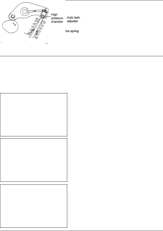
Auto Lash Adjuster
Construction
These engines have auto lash adjusters that eliminate the need for valve clearance adjustment and reduce noises of the valve system. The auto lash adjuster automatically absorbs change in the valve clearance caused by engine temperature change or wear of parts and adjusts the valve clearance always to zero.
Operation of Auto Lash Adjuster
(1)At Start of Valve Lift
When the cam lifts up the rocker arm, the hydraulic pressure immediately forces the ball in the high pressure chamber against the seat, closing the high pressure chamber.
(2)During Valve Lift
A small amount of oil leaks from the high pressure chamber through a clearance between the body inside and the plunger outside.
(3)At end of Valve Lift
The plunger spring forces the body back to the initial position and oil is supplied to the high pressure chamber to make up for the leaked oil.
G424 Service Manual |
27 |
Engine System |

Intake and Exhaust System
Gasoline Engine
The intake manifold employs the shape having good intake performance.
The exhaust manifold employs a dual type and intend the reduction of output loss due to exhaust interference.
G424 Service Manual |
28 |
Engine System |
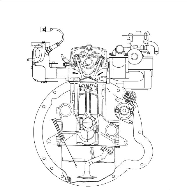
LPG Engine (Low Emission Version)
|
|
|
|
|
|
|
|
|
|
|
|
G424 Service Manual |
29 |
Engine System |
|
 Loading...