

OPERATION and MAINTENANCE
MANUAL
COMPRESSOR MODEL
P600/XP535WCU-T4i (E90)
HP450/VHP400WCU-T4i (E91)
This manual contains important safety information.
Do not destroy this manual.
This manual must be available to the personnel who operate and maintain this compressor.
Doosan Infracore Portable Power
1293 Glenway Drive
Statesville, N.C. 28625
DoosanPortablePower.com
P/N: 46614501 (07-2012) Rev A

2

TABLE OF CONTENTS
Operation & Maintenance Manual
TITLE PAGE
FOREWORD . . . . . . . . . . . . . . . . . . . . . . . . . . . . . . . . . . . . . . . . . . . . . . . . . . . . . . . . . . . . . . 7
Information . . . . . . . . . . . . . . . . . . . . . . . . . . . . . . . . . . . . . . . . . . . . . . . . . . . . . . . . . . . . . . . . . . . 8
SAFETY . . . . . . . . . . . . . . . . . . . . . . . . . . . . . . . . . . . . . . . . . . . . . . . . . . . . . . . . . . . . . . . . 11
Safety Precautions. . . . . . . . . . . . . . . . . . . . . . . . . . . . . . . . . . . . . . . . . . . . . . . . . . . . . . . . . . . . 12
Compressed Air . . . . . . . . . . . . . . . . . . . . . . . . . . . . . . . . . . . . . . . . . . . . . . . . . . . . . . . . . . . . . . . . . . .13
Exhaust System . . . . . . . . . . . . . . . . . . . . . . . . . . . . . . . . . . . . . . . . . . . . . . . . . . . . . . . . . . . . . . . . . . . 14
Materials . . . . . . . . . . . . . . . . . . . . . . . . . . . . . . . . . . . . . . . . . . . . . . . . . . . . . . . . . . . . . . . . . . . . . . . . . 14
Battery. . . . . . . . . . . . . . . . . . . . . . . . . . . . . . . . . . . . . . . . . . . . . . . . . . . . . . . . . . . . . . . . . . . . . . . . . . .15
Radiator. . . . . . . . . . . . . . . . . . . . . . . . . . . . . . . . . . . . . . . . . . . . . . . . . . . . . . . . . . . . . . . . . . . . . . . . . .15
Transport. . . . . . . . . . . . . . . . . . . . . . . . . . . . . . . . . . . . . . . . . . . . . . . . . . . . . . . . . . . . . . . . . . . . . . . . .16
Decals. . . . . . . . . . . . . . . . . . . . . . . . . . . . . . . . . . . . . . . . . . . . . . . . . . . . . . . . . . . . . . . . . . . . . . . . . . . 18
Decals. . . . . . . . . . . . . . . . . . . . . . . . . . . . . . . . . . . . . . . . . . . . . . . . . . . . . . . . . . . . . . . . . . . . . . . . . . . 24
NOISE EMISSION. . . . . . . . . . . . . . . . . . . . . . . . . . . . . . . . . . . . . . . . . . . . . . . . . . . . . . . . . 29
Noise Emission . . . . . . . . . . . . . . . . . . . . . . . . . . . . . . . . . . . . . . . . . . . . . . . . . . . . . . . . . . . . . . 30
Compressor Noise Emission Control Information. . . . . . . . . . . . . . . . . . . . . . . . . . . . . . . . . . . . . . . . . .30
Maintenance Log . . . . . . . . . . . . . . . . . . . . . . . . . . . . . . . . . . . . . . . . . . . . . . . . . . . . . . . . . . . . . 31
Noise Emission Warranty . . . . . . . . . . . . . . . . . . . . . . . . . . . . . . . . . . . . . . . . . . . . . . . . . . . . . . . . . . . . 31
Introduction . . . . . . . . . . . . . . . . . . . . . . . . . . . . . . . . . . . . . . . . . . . . . . . . . . . . . . . . . . . . . . . . . . . . . . .32
Maintenance Schedule . . . . . . . . . . . . . . . . . . . . . . . . . . . . . . . . . . . . . . . . . . . . . . . . . . . . . . . . . . . . . .32
A. Compressed Air Leaks . . . . . . . . . . . . . . . . . . . . . . . . . . . . . . . . . . . . . . . . . . . . . . . . . . . . . . . 32
B. Safety and Control Systems. . . . . . . . . . . . . . . . . . . . . . . . . . . . . . . . . . . . . . . . . . . . . . . . . . . . .32
C. Acoustic Materials . . . . . . . . . . . . . . . . . . . . . . . . . . . . . . . . . . . . . . . . . . . . . . . . . . . . . . . . . . . .32
D. Fasteners. . . . . . . . . . . . . . . . . . . . . . . . . . . . . . . . . . . . . . . . . . . . . . . . . . . . . . . . . . . . . . . . . . .33
E. Enclosure Panels . . . . . . . . . . . . . . . . . . . . . . . . . . . . . . . . . . . . . . . . . . . . . . . . . . . . . . . . . . . . .33
F. Air Intake and Engine Exhaust. . . . . . . . . . . . . . . . . . . . . . . . . . . . . . . . . . . . . . . . . . . . . . . . . . .33
G. Cooling Systems . . . . . . . . . . . . . . . . . . . . . . . . . . . . . . . . . . . . . . . . . . . . . . . . . . . . . . . . . . . . .33
H. Isolation Mounts. . . . . . . . . . . . . . . . . . . . . . . . . . . . . . . . . . . . . . . . . . . . . . . . . . . . . . . . . . . . . .33
I. Engine Operation. . . . . . . . . . . . . . . . . . . . . . . . . . . . . . . . . . . . . . . . . . . . . . . . . . . . . . . . . . . . . . 33
J. Fuels and Lubricants . . . . . . . . . . . . . . . . . . . . . . . . . . . . . . . . . . . . . . . . . . . . . . . . . . . . . . . . . .33
GENERAL DATA . . . . . . . . . . . . . . . . . . . . . . . . . . . . . . . . . . . . . . . . . . . . . . . . . . . . . . . . . 35
General Data Information . . . . . . . . . . . . . . . . . . . . . . . . . . . . . . . . . . . . . . . . . . . . . . . . . . . . . . 36
OPERATING INSTRUCTIONS . . . . . . . . . . . . . . . . . . . . . . . . . . . . . . . . . . . . . . . . . . . . . . . 39
Control Panel . . . . . . . . . . . . . . . . . . . . . . . . . . . . . . . . . . . . . . . . . . . . . . . . . . . . . . . . . . . . . . . . . . . . .40
Control/Gauge Panel. . . . . . . . . . . . . . . . . . . . . . . . . . . . . . . . . . . . . . . . . . . . . . . . . . . . . . . . . . . . . . . .40
Lifting . . . . . . . . . . . . . . . . . . . . . . . . . . . . . . . . . . . . . . . . . . . . . . . . . . . . . . . . . . . . . . . . . . . . . . . . 47
3

TABLE OF CONTENTS
Operation & Maintenance Manual
TITLE PAGE
Before Towing . . . . . . . . . . . . . . . . . . . . . . . . . . . . . . . . . . . . . . . . . . . . . . . . . . . . . . . . . . . . . . . . .47
Setting Up . . . . . . . . . . . . . . . . . . . . . . . . . . . . . . . . . . . . . . . . . . . . . . . . . . . . . . . . . . . . . . . . . . . . . . .48
Compressor Mounting. . . . . . . . . . . . . . . . . . . . . . . . . . . . . . . . . . . . . . . . . . . . . . . . . . . . . . . . . . . . . . . 48
Service Air Connection(s) . . . . . . . . . . . . . . . . . . . . . . . . . . . . . . . . . . . . . . . . . . . . . . . . . . . . . . . . . . . .48
Air Hose Restraint Installation. . . . . . . . . . . . . . . . . . . . . . . . . . . . . . . . . . . . . . . . . . . . . . . . . . . . . . . . .49
Before Starting . . . . . . . . . . . . . . . . . . . . . . . . . . . . . . . . . . . . . . . . . . . . . . . . . . . . . . . . . . . . . . . . . . . . 50
Starting . . . . . . . . . . . . . . . . . . . . . . . . . . . . . . . . . . . . . . . . . . . . . . . . . . . . . . . . . . . . . . . . . . . . . . . . . .52
Normal Operation . . . . . . . . . . . . . . . . . . . . . . . . . . . . . . . . . . . . . . . . . . . . . . . . . . . . . . . . . . . . . . . . . .53
Shutdown . . . . . . . . . . . . . . . . . . . . . . . . . . . . . . . . . . . . . . . . . . . . . . . . . . . . . . . . . . . . . . . . . . . . . . . . 54
Decommissioning . . . . . . . . . . . . . . . . . . . . . . . . . . . . . . . . . . . . . . . . . . . . . . . . . . . . . . . . . . . . . . . . . .55
MAINTENANCE . . . . . . . . . . . . . . . . . . . . . . . . . . . . . . . . . . . . . . . . . . . . . . . . . . . . . . . . . . 57
General Information . . . . . . . . . . . . . . . . . . . . . . . . . . . . . . . . . . . . . . . . . . . . . . . . . . . . . . . . . . . . . . . .58
Maintenance Precautions . . . . . . . . . . . . . . . . . . . . . . . . . . . . . . . . . . . . . . . . . . . . . . . . . . . . . . . . . . . .58
Maintenance Schedule . . . . . . . . . . . . . . . . . . . . . . . . . . . . . . . . . . . . . . . . . . . . . . . . . . . . . . . . . . . . . .60
Scavenge Line . . . . . . . . . . . . . . . . . . . . . . . . . . . . . . . . . . . . . . . . . . . . . . . . . . . . . . . . . . . . . . . . . . . .63
Compressor Oil Filter . . . . . . . . . . . . . . . . . . . . . . . . . . . . . . . . . . . . . . . . . . . . . . . . . . . . . . . . . . . . . . .63
Removal . . . . . . . . . . . . . . . . . . . . . . . . . . . . . . . . . . . . . . . . . . . . . . . . . . . . . . . . . . . . . . . . . . . . . .63
lnspection . . . . . . . . . . . . . . . . . . . . . . . . . . . . . . . . . . . . . . . . . . . . . . . . . . . . . . . . . . . . . . . . . . . . . 63
Reassembly . . . . . . . . . . . . . . . . . . . . . . . . . . . . . . . . . . . . . . . . . . . . . . . . . . . . . . . . . . . . . . . . . . .63
Compressor Oil Separator Element . . . . . . . . . . . . . . . . . . . . . . . . . . . . . . . . . . . . . . . . . . . . . . . . . . . .64
Removal . . . . . . . . . . . . . . . . . . . . . . . . . . . . . . . . . . . . . . . . . . . . . . . . . . . . . . . . . . . . . . . . . . . . . .64
lnspection . . . . . . . . . . . . . . . . . . . . . . . . . . . . . . . . . . . . . . . . . . . . . . . . . . . . . . . . . . . . . . . . . . . . . 64
Reassembly . . . . . . . . . . . . . . . . . . . . . . . . . . . . . . . . . . . . . . . . . . . . . . . . . . . . . . . . . . . . . . . . . . .64
Compressor Oil Cooler, Engine Radiator, and other Heat Exchangers . . . . . . . . . . . . . . . . . . . . . . . . . 65
Air Filter Elements. . . . . . . . . . . . . . . . . . . . . . . . . . . . . . . . . . . . . . . . . . . . . . . . . . . . . . . . . . . . . . . . . .66
Removal . . . . . . . . . . . . . . . . . . . . . . . . . . . . . . . . . . . . . . . . . . . . . . . . . . . . . . . . . . . . . . . . . . . . . .66
Inspection . . . . . . . . . . . . . . . . . . . . . . . . . . . . . . . . . . . . . . . . . . . . . . . . . . . . . . . . . . . . . . . . . . . . . 66
Reassembly . . . . . . . . . . . . . . . . . . . . . . . . . . . . . . . . . . . . . . . . . . . . . . . . . . . . . . . . . . . . . . . . . . .66
Ventilation . . . . . . . . . . . . . . . . . . . . . . . . . . . . . . . . . . . . . . . . . . . . . . . . . . . . . . . . . . . . . . . . . . . . . . . .67
Cooling Fan Drive . . . . . . . . . . . . . . . . . . . . . . . . . . . . . . . . . . . . . . . . . . . . . . . . . . . . . . . . . . . . . . . . . . 67
Fuel System . . . . . . . . . . . . . . . . . . . . . . . . . . . . . . . . . . . . . . . . . . . . . . . . . . . . . . . . . . . . . . . . . . . . . . 67
Fuel Filter Water Separator. . . . . . . . . . . . . . . . . . . . . . . . . . . . . . . . . . . . . . . . . . . . . . . . . . . . . . . . . . . 67
Charge Air Cooler Pipework . . . . . . . . . . . . . . . . . . . . . . . . . . . . . . . . . . . . . . . . . . . . . . . . . . . . . . . . . . 67
Hoses . . . . . . . . . . . . . . . . . . . . . . . . . . . . . . . . . . . . . . . . . . . . . . . . . . . . . . . . . . . . . . . . . . . . . . . . . . .67
Electrical System. . . . . . . . . . . . . . . . . . . . . . . . . . . . . . . . . . . . . . . . . . . . . . . . . . . . . . . . . . . . . . . . . . .68
Battery. . . . . . . . . . . . . . . . . . . . . . . . . . . . . . . . . . . . . . . . . . . . . . . . . . . . . . . . . . . . . . . . . . . . . . . . . . .68
Pressure System. . . . . . . . . . . . . . . . . . . . . . . . . . . . . . . . . . . . . . . . . . . . . . . . . . . . . . . . . . . . . . . . . . .68
Tire Pressure. . . . . . . . . . . . . . . . . . . . . . . . . . . . . . . . . . . . . . . . . . . . . . . . . . . . . . . . . . . . . . . . . . . . . .68
Running Gear/Wheels. . . . . . . . . . . . . . . . . . . . . . . . . . . . . . . . . . . . . . . . . . . . . . . . . . . . . . . . . . . . . . .68
Lubrication. . . . . . . . . . . . . . . . . . . . . . . . . . . . . . . . . . . . . . . . . . . . . . . . . . . . . . . . . . . . . . . . . . . . . . . .69
Engine Oil. . . . . . . . . . . . . . . . . . . . . . . . . . . . . . . . . . . . . . . . . . . . . . . . . . . . . . . . . . . . . . . . . . . . . 69
Compressor Oil. . . . . . . . . . . . . . . . . . . . . . . . . . . . . . . . . . . . . . . . . . . . . . . . . . . . . . . . . . . . . . . . . 69
Running Gear Wheel Bearings . . . . . . . . . . . . . . . . . . . . . . . . . . . . . . . . . . . . . . . . . . . . . . . . . . . . . . . .70
Pressure Regulator Adjusting Instructions . . . . . . . . . . . . . . . . . . . . . . . . . . . . . . . . . . . . . . . . . . . . . . .71
Torque Values. . . . . . . . . . . . . . . . . . . . . . . . . . . . . . . . . . . . . . . . . . . . . . . . . . . . . . . . . . . . . . . . . . . . .72
4

TABLE OF CONTENTS
Operation & Maintenance Manual
TITLE PAGE
LUBRICATION . . . . . . . . . . . . . . . . . . . . . . . . . . . . . . . . . . . . . . . . . . . . . . . . . . . . . . . . . . . 75
General Information . . . . . . . . . . . . . . . . . . . . . . . . . . . . . . . . . . . . . . . . . . . . . . . . . . . . . . . . . . . . . . . .76
Compressor Oil Change . . . . . . . . . . . . . . . . . . . . . . . . . . . . . . . . . . . . . . . . . . . . . . . . . . . . . . . . . . . . .76
Portable Compressor Oil Chart. . . . . . . . . . . . . . . . . . . . . . . . . . . . . . . . . . . . . . . . . . . . . . . . . . . . . . . .78
TROUBLESHOOTING . . . . . . . . . . . . . . . . . . . . . . . . . . . . . . . . . . . . . . . . . . . . . . . . . . . . . 79
Introduction . . . . . . . . . . . . . . . . . . . . . . . . . . . . . . . . . . . . . . . . . . . . . . . . . . . . . . . . . . . . . . . . . . . . . . .80
Think Before Acting . . . . . . . . . . . . . . . . . . . . . . . . . . . . . . . . . . . . . . . . . . . . . . . . . . . . . . . . . . . . .80
Do the Simplest Things First . . . . . . . . . . . . . . . . . . . . . . . . . . . . . . . . . . . . . . . . . . . . . . . . . . . . . .80
Double Check Before Disassembly . . . . . . . . . . . . . . . . . . . . . . . . . . . . . . . . . . . . . . . . . . . . . . . . .80
Find and Correct Basic Cause . . . . . . . . . . . . . . . . . . . . . . . . . . . . . . . . . . . . . . . . . . . . . . . . . . . . .80
Troubleshooting Chart. . . . . . . . . . . . . . . . . . . . . . . . . . . . . . . . . . . . . . . . . . . . . . . . . . . . . . . . . . . . . . .81
Diagnostic Codes . . . . . . . . . . . . . . . . . . . . . . . . . . . . . . . . . . . . . . . . . . . . . . . . . . . . . . . . . . . . . . .85
. . . . . . . . . . . . . . . . . . . . . . . . . . . . . . . . . . . . . . . . . . . . . . . . . . . . . . . . . . . . . . . . . . . . . . . . . . . . .88
Engine Diagnostic Codes - Cummins Engine with CM2250 Controller . . . . . . . . . . . . . . . . . . . . . . 89
OPTIONS . . . . . . . . . . . . . . . . . . . . . . . . . . . . . . . . . . . . . . . . . . . . . . . . . . . . . . . . . . . . . . 103
IQ System . . . . . . . . . . . . . . . . . . . . . . . . . . . . . . . . . . . . . . . . . . . . . . . . . . . . . . . . . . . . . . . . . . 104
Theory of Operation . . . . . . . . . . . . . . . . . . . . . . . . . . . . . . . . . . . . . . . . . . . . . . . . . . . . . . . . . . . . . . .104
IQ System Configuration. . . . . . . . . . . . . . . . . . . . . . . . . . . . . . . . . . . . . . . . . . . . . . . . . . . . . . . . . . . . 106
Maintenance . . . . . . . . . . . . . . . . . . . . . . . . . . . . . . . . . . . . . . . . . . . . . . . . . . . . . . . . . . . . . . . . . . . . .107
Filter Replacement . . . . . . . . . . . . . . . . . . . . . . . . . . . . . . . . . . . . . . . . . . . . . . . . . . . . . . . . . . . . . . . . 108
5

6

Foreword
7

Operation & Maintenance Manual Foreword
Information
The contents of this manual are considered to be proprietary and confidential to Doosan
Infracore Portable Power (herein referred to as “Portable Power”), and should not be
reproduced without the prior written permission of Portable Power.
Nothing contained in this document is intended to extend any promise, warranty or
representation, expressed or implied, regarding the Portable Power products described
herein. Any such warranties or other terms and conditions of sale of products shall be in
accordance with the standard terms and conditions of sale for such products, which are
available upon request.
This manual contains instructions and technical data to cover all routine operation and
scheduled maintenance tasks by operation and maintenance staff. Major overhauls are
outside the scope of this manual and should be referred to an authorized Portable Power
Service department.
All components, accessories, pipes, and connectors added to the compressed air system
should be:
• of good quality, procured from a reputable manufacturer and, wherever possible, be
of a type approved by Portable Power.
• clearly rated for a pressure at least equal to the compressor safety valve setting.
• compatible with the compressor oil.
• accompanied with instructions for safe installation, operation, and maintenance.
Details of approved equipment are available from the Portable Power Service departments.
The use of repair parts other than those included within the approved parts list may create
hazardous conditions over which Portable Power has no control. Therefore, Portable Power
cannot be held responsible for equipment in which non-approved repair parts are installed.
Portable Power reserves the right to make changes and improvements to products without
notice and without incurring any obligation to make such changes or add such improvements
to products sold previously.
The intended uses of this compressor are outlined below and examples of unap proved usage
are also given. However, Portable Power cannot anticipate every application or work situation
that may arise. If in doubt, consult supervision.
This compressor has been designed and supplied for above ground operation to be used for
compression of normal ambient air containing no additional gases, vapors, or particles within
the ambient temperature range specified in the General Data Section of this manual.
8

Foreword Operation & Maintenance Manual
This compressor should NOT be used:
A. For direct or indirect human consumption of the compressed air.
B. Outside the ambient temperature range specified in the General Data Section
of this manual.
C. When an actual or forese eable risk of hazardou s levels of fla mmable g ases or
vapors exists.
D. With other than Portable Power approved components.
E. With guards, controls, or switches missing or disabled.
F. For storage or transportation of materials inside or on the enclosure.
Portable Power accepts no responsibility for errors in translation of this manual from the
original English version.
You, as the customer, are expected to provide certain service and maintenance items. Your
Portable Power dealer will provide all other more detailed service and maintenance items on
a special preventive maintenance schedule for each compressor. It is very important that the
minimum service and maintenance requirements explained in this manual be performed at the
required intervals. Exceeding these intervals may reduce the reliability of the compressor.
The purpose of this manual is to train the operator with functions, operation, and basic service
and maintenance requirements of the compressor. During the preparation of this manual,
every effort was made to ensure the accuracy and adequacy of the contents.
Your Portable Power dealer will assist with setup and initial startup of the compressor and will
also provide brief operating and service instructions. Before starting the compressor, this
manual and instructions should be carefully read to obtain a thorough knowledge of the duties
to be performed. Please take pride in the compressor, keep it clean and in good mechanical
condition.
To enable proper maintenance records, Portable Power provides a Noise Emission Control
Maintenance Log in the Noise Emission Section of this manual. The Noise Emission Section
contains a recommended Maintenance schedule and provides space in the log for the
technician to note what service and maintenance was done, by whom, where, and when.
9

Operation & Maintenance Manual Foreword
10

Safety
11

Operation & Maintenance Manual Safety
Safety Precautions
Never operate the compressor without first observing all safety warnings and carefully reading
the Operation and Maintenance Manual shipped from the factory with this compressor.
Ensure the operator reads and understands the decals and consults the manuals before
operation or performing maintenance.
Ensure all maintenance personnel are adequately trained, competent, and have read the
manuals.
Ensure all protective covers are in place and the canopy/doors are closed during operation.
The specification of this compressor is such that the compressor is not suitable for use in
flammable gas risk areas. If such an application is required, all local regulations, codes of
practice, and site rules must be observed. To ensure the compressor can operate in a safe
and reliable manner, additional equipment such as gas detection, exhaust spark arrestors,
and intake (shut-off) valves may be required, dependent on local regula tions or the degree of
risk involved.
A weekly visual check must be made of all fasteners/fixing screws securing mechanical parts.
In particular, safety-related parts such as coupling hitch, drawbar components, wheels, tires,
and lifting bail should be checked for total security.
All components which are loose, damaged, or unserviceable must be rectified without delay.
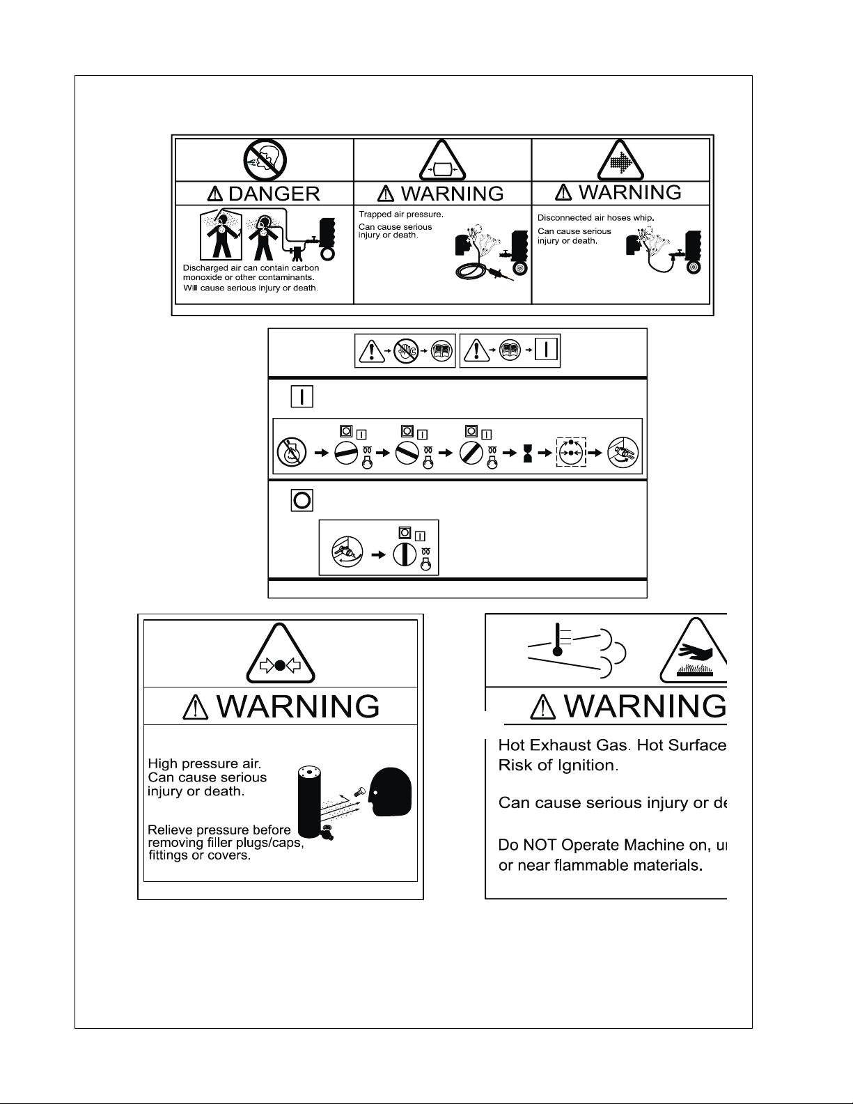
Air discharged from this compressor may contain carbon monoxide or other contaminants
which will cause serious injury or death. Do not breathe discharged air.
This compressor produces loud noise with the doors open or service valve vented. Extended
exposure to loud noise can cause hearing loss. Always wear hearing protection when doors
are open or service valve is vented.
Never inspect or service the compressor without first disconnecting battery ca ble(s) to prevent
accidental starting.
Do not use petroleum products (solvents or fuels) under high pressure as this can penetrate
the skin and result in serious illness. Wear eye protection while cleanin g the compressor with
compressed air to prevent debris from injuring eye(s).
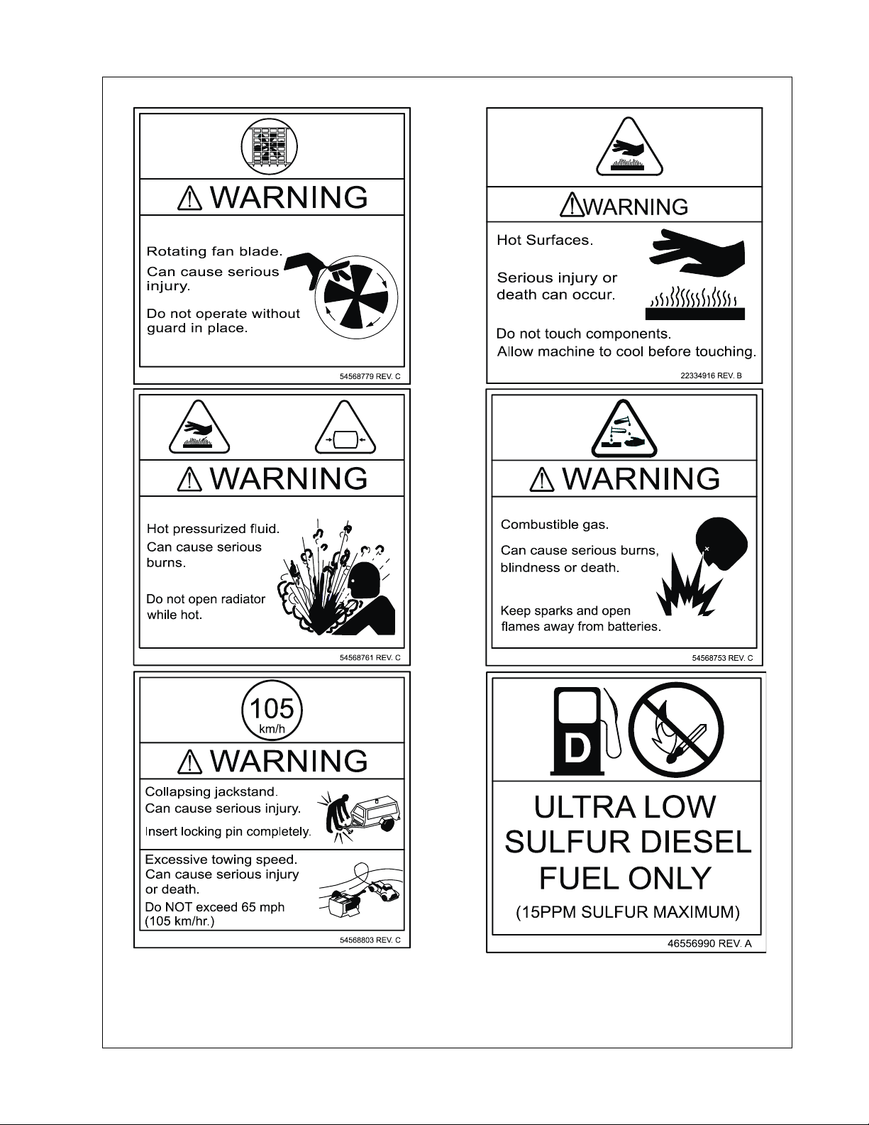
Rotating fan blade can cause serious injury. Do not operate without fan guard in place.
Use care to avoid contacting hot surfaces (engine exhaust manifold and piping, air receiver,
and air discharge piping, etc.).
Ether is an extremely volatile, highly flammable gas. When it is specified as a starting aid, use
sparingly. Do not use Ether if the engine has glow plugs or inlet heater starting aids. Engine
damage will result.
Never operate the compressor with guards, covers, or screens removed. Keep hands, hair,
clothing, tools, blow gun tips, etc. well away from moving parts.
12

Safety Operation & Maintenance Manual
Compressed Air
Compressed air can be dangerous if incorrectly handled. Prior to performing maintenance or
service on the compressor, ensure all pressure is vented from the system and the compressor
cannot be started accidentally.
Ensure the compressor is operating at the rated pressure and the rated pressure is known to
all relevant personnel.
All air pressure equipment installed in, or connected to, the compressor must have safe
working pressure ratings of at least the compressor safety valve setting.
If more than one compressor is connected to one common downstream plant, effective check
valves and isolation valves must be fitted and controlled by work procedures, to ensure one
compressor cannot accidentally be pressurized or over pressurized by another.
Compressed air must NOT be used for a direct feed to any form of breathing apparatus or
mask.
Compressed air can cause serious injury or death. Relieve pressure before removing filler
plugs/caps, fittings, or covers.
Air pressure can remain trapped in air supply line which can result in serious injury or death.
Always carefully vent air supply line at tool or vent valve before performing any service or
maintenance.
Discharged air contains a very small percentage of compressor lubricating oil and ca re should
be taken to ensure downstream equipment is compatible.
If discharged air is to be ultimately released into a confined space, adequate ventilation must
be provided.
When using compressed air, always use appropriate personal protective equipment.
All pressure containing parts, especially flexible hoses and their couplings, must be regularly
inspected, be free from defects, and be replaced according to the manual instructions.
Avoid bodily contact with compressed air.
The safety valve located in the separator tank must be checked periodically for correct
operation.
Whenever the compressor is stopped, air will flow back into th e compressor from downstream
devices or systems unless the service valve is closed. Install a check valve at the compressor
service valve to prevent reverse flow in the event of an unexpected shutdown when the service
valve is open.
Disconnected air hoses whip and can cause serious injury or death. Always attach a safety
flow restrictor to each hose at the source of supply or branch line in accordance with OSHA
Regulation 29CFR Section 1926.302(b).
Never allow the compressor to sit stopped with pressure in the separator tank or piping.
13
Operation & Maintenance Manual Safety
Exhaust System
Hot engine exhaust gas and hot exhaust system surfaces are produced during and after
compressor operation. Avoid contact with exhaust gas and hot exhaust system surfaces. Ke ep
flammable and combustible materials away. Do not operate compressor on, under, or near
flammable or combustible materials.
The potential for higher temperatures is present when the exhaust aftertreatment system
undergoes regeneration. Refer to Engine Manual for further safety instructions and
information on the exhaust aftertreatment system and controls.
Materials
The following substances may be produced during the operation of this compressor:
• brake lining dust
• engine exhaust fumes
!
WARNING
Avoid inhalation of material substances.
Ensure that adequate ventilation of the cooling system and exhaust gases is maintained at all
times.
The following substances are used in the manufacture of this compressor and may be
hazardous to health if used incorrectly:
• antifreeze
• compressor oil
• engine oil
• preservative grease, lubricating grease
• rust preventative
• diesel fuel
• battery electrolyte
!
WARNING
Avoid ingestion, skin contact, and inhalation of fumes.
Should compressor oil come into contact with the eyes, irrigate with water for at least 5
minutes.
14
Safety Operation & Maintenance Manual
Should compressor oil come into contact with the skin, wash off immediately. Consult a
physician if large amounts of compressor oil are ingested or if compressor oil is inhaled. Never
give fluids or induce vomiting if the patient is unconscious or having convulsions.
Safety data sheets for compressor and engine oils should be obtained from the oil supplier.
Do NOT start or operate this compressor in a confined area. Avoid breathing exhaust fumes
when working on or near the compressor.
This compressor may include such materials as oil, diesel fuel, antifreeze, brake fluid, oil/air
filters, and batteries which may require proper disposal when performing maintenance or
service tasks. Contact local authorities for proper disposal of these materials.
Battery
A battery contains sulfuric acid and can produce gases which are corrosive and potentially
explosive. Avoid contact with skin, eyes, and clothing. In case of contact, flush area
immediately with water.
!
WARNING
Do not attempt to jump-start a frozen battery since this may cause it to
explode.
Exercise extreme caution when using an external method to jump-start a unit. Verify the
electrical systems on the weak battery system and the external jump system are the same
voltage type system, 12VDC or 24VDC. Connect the Positive (+) terminal of the external
system to the Positive (+) terminal on the weak system. Connect the Negative (-) terminal of
the external system to the Negative (-) terminal of the weak system. Always disconnect the
two systems in reverse order.
Radiator
Hot engine coolant and steam can cause injury. Ensure the Radiator Pressure Cap is removed
with due care and attention.
Do not remove the pressure cap from a HOT radiator. Allow radiator to coo l be fore r emoving
pressure cap.
15
Operation & Maintenance Manual Safety
!
WARNING
Hot engine coolant and steam can cause injury. When adding coolant or
antifreeze solution to the engine radiator, stop the engine and allow
radiator to cool prior to releasing the radiator pressure cap. Using a cloth
to protect the hand, slowly release the radiator pressure cap, absorbing
any released fluid with the cloth. Do not remove the radiator pressure cap
until all excess fluid is released and the engine cooling system fully
depressurized.
!
WARNING
Follow the instructions provided by the antifreeze supplier when adding
or draining the antifreeze solution. It is advisable to wear personal
protective equipment to prevent skin and eye contact with the antifreeze
solution.
Transport
When loading or transporting the compressor, ensure that the specified lifting and tie down
points are used.
When loading or transporting the compressor, ensure that the towing vehicle, its size, weight,
towing hitch, and electrical supply are all suitable to provide safe and stable towing at sp eeds
either, up to the legal maximum for the country in which it is being towed or as specified for
the compressor model if lower than the legal maximum. Do not exceed gross vehicle weight
rating.
Before towing the compressor, ensure:
• the tires and towing hitch are in a serviceable condition and tires are properly inflate d.
• the canopy is secure.
• all ancillary equipment is stored in a safe and secure manner.
• the brakes and lights are functioning correctly and meet necessary road traffic
requirements.
• breakaway cables/safety chains are connected to the towing vehicle.
The compressor must be towed in a level attitude in order to maintain correct handling,
braking, and lighting functions. This can be achieved by correct selection and adjustment of
the vehicle towing hitch and, on variable height running gear, adjustment of the drawbar.
1. Ensure wheels, tires, and drawbar connectors are in safe operating condition
and drawbar is properly connected before towing.
2. When parking, always use the handbrake and, if necessary, suitable wheel
chocks.
16

Safety Operation & Maintenance Manual
Safety chains/breakaway cable and their adjustment (where fitted).
Ensure breakaway cable is securely coupled to the towed compressor and also to a
substantial anchorage point on the towing vehicle.
Ensure cable length is as short as possible, while still allowing enough slackness for the towed
compressor to articulate without the brake being applied.
Attach safety chains to the towing vehicle at substantial anchorage points of suitable strength.
Ensure effective chain length is as short as possible while still allowing normal articulation of
the towed compressor and proper operation of the breakaway cable.
17
Operation & Maintenance Manual Safety
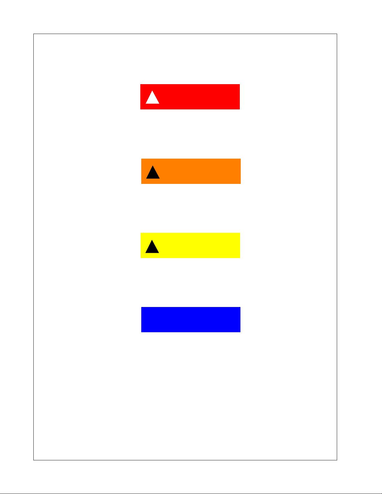
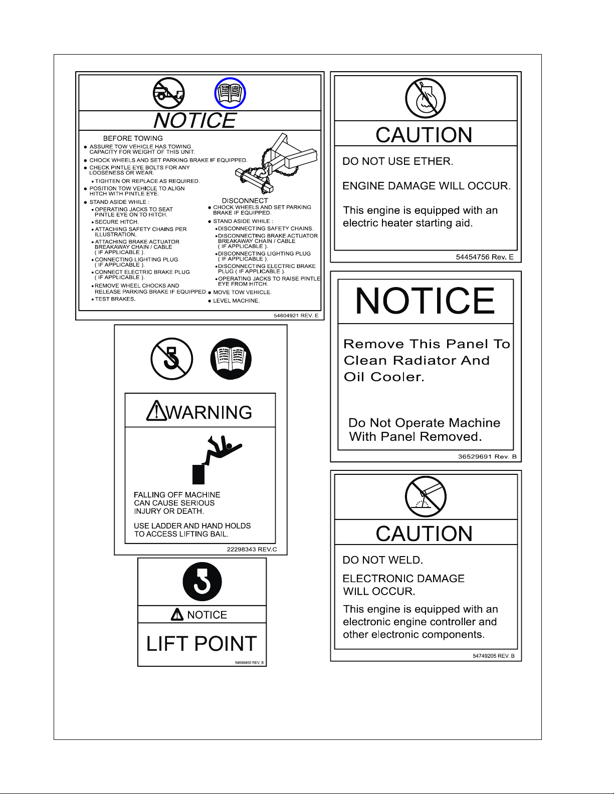
Decals
Decals are located on the compressor to point out potential safety hazards. Read and follow
these instructions. If you do not understand these instructions, inform your supervisor.
!
DANGER
(Red Background)
Indicates the presence of a hazard which WILL cause serious injury,
death, or property damage, if ignored.
!
WARNING
(Orange Background)
Indicates the presence of a hazard which CAN cause serious injury,
death, or property damage, if ignored.
!
CAUTION
(Yellow Background)
Indicates the presence of a hazard which WILL or CAN cause injury or
property damage, if ignored.
NOTICE
(Blue Background)
Indicates important set-up, operating, or maintenance information.
18
Safety Operation & Maintenance Manual
Free Safety Decals
To promote communication of Safety Warnings on products
manufactured by the Portable Power Division in S tatesville, N.C., Safety
Decals are available FREE of charge. Safety Decals are identified by
the decal heading: DANGER, WARNING, CAUTION, NOTICE.
Decal part numbers are located in the lower right hand corner of each
decal and are also listed in the compressor Parts Manual. Submit orders
for Safety Decals to the Statesville Parts Service Dept. The no charge
order should contain only Safety Decals.
Help promote product safety! Ensure decals are present on the
compressor. Replace decals that are not readable.
19
Operation & Maintenance Manual Safety
8
Do not breathe this air.
Close service valve and
operate tool to vent
trapped air before
performing any service.
5 S
When using air tools
attach safety device
(OSHA Valve) at source of
air supply for each tool.
3M
54749163 REV. C
54629902 REV. C
Hot
54568795 REV. C
20
465598
Safety Operation & Maintenance Manual
21
Operation & Maintenance Manual Safety
22
Safety Operation & Maintenance Manual
23
Operation & Maintenance Manual Safety
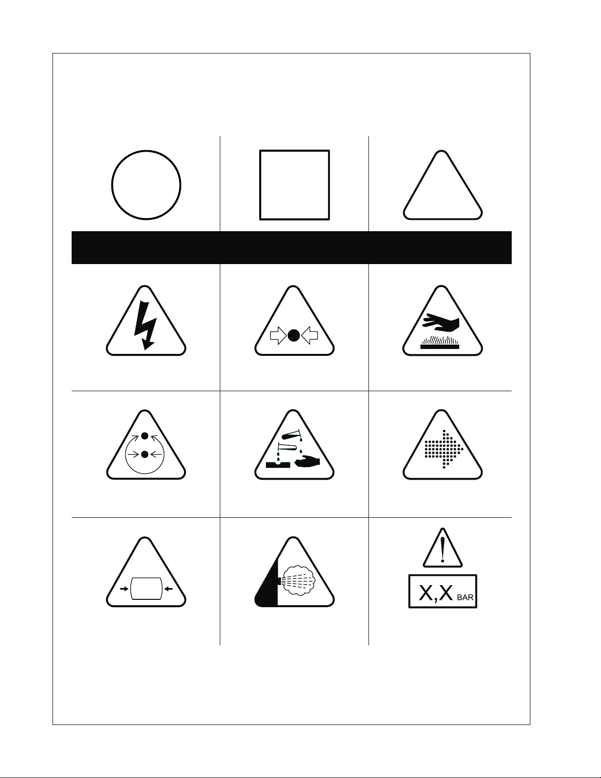
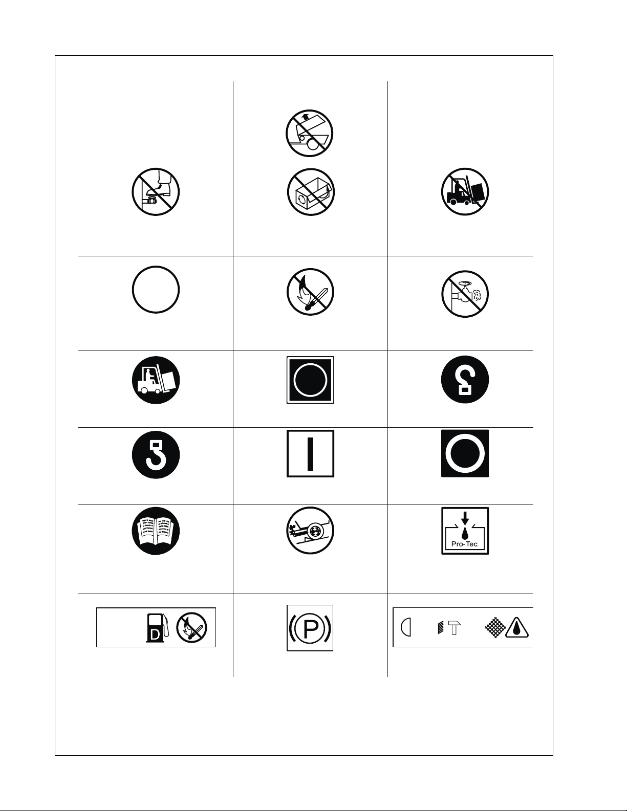
Decals
Graphic Form and Meaning of ISO Symbols
Prohibition / Mandatory Information / Instructions Warning
WARNING: Electrical Shock Risk
WARNING: Pressure Control WARNING: Corrosion Risk WARNING: Air/Gas Flow or
WARNING: Pressurized Vessel WARNING: Hot and harmful exhaust
WARNING: Pressurized Component
or System
gas
WARNING: Hot Surface
Air Discharge
WARNING: Maintain correct tire
pressure (Refer to the GENERAL
INFORMATION section of this manua
24
Safety Operation & Maintenance Manual
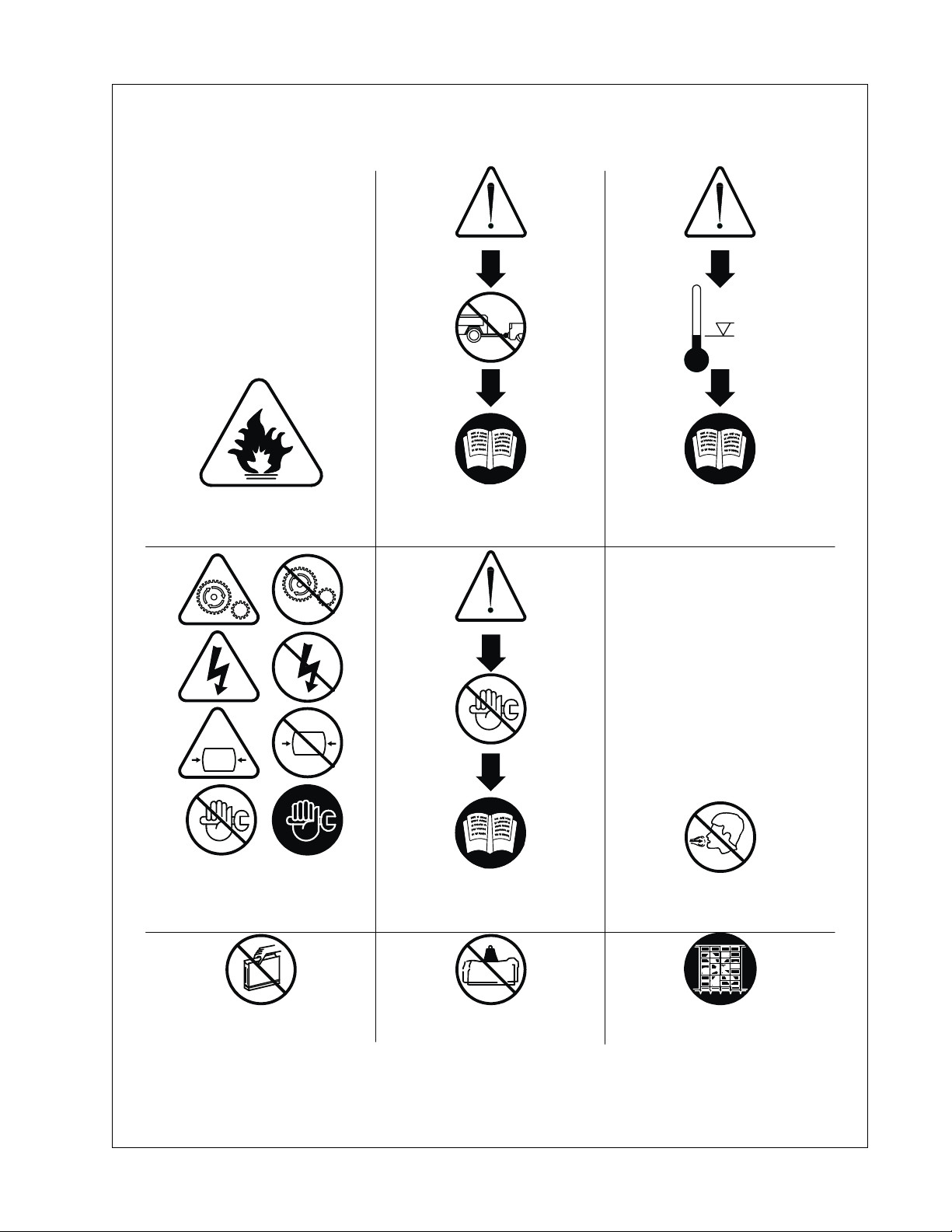
o
0C
WARNING: Flammable Liquid
WARNING: Do not undertake any
maintenance on this machine until
the electrical supply is disconnected
and the air pressure is totally relieved
WARNING: Before connecting the tow
bar or commencing to tow consult the
Operation and Maintenance Manual
WARNING: Consult the Operation and
Maintenance manual before
commencing any maintenance
WARNING: For operating temperature
o
below 0 C, consult the Operation and
Maintenance Manual
Do not Breathe the compressed air
from this machine
Do not remove the Operation and
Maintenance manual and manual
Do not stack Do not operate the machine without
the guard being fitted
holder from this machine
25
Operation & Maintenance Manual Safety
Do not stand on any service valve
or other parts of the pressure system
Do not operate with doors or
enclosure open
Do not use fork lift truck
from this side
XX
km/h
Do not exceed trailer speed limit No open flames
Use fork lift truck from this side only Emergency stop Tie down point
Lifting point ON (power) OFF (power)
Do not open service valve before
the air hose is attached
Read the Operation and Maintenance
manual before operation or
maintenance of this machine is
undertaken
DIESEL
Diesel fuel
No open flames
When parking use prop stand,
handbrake, and wheel chocks
Parking Brake Rough Service Designation
Compressor oil filling
IP541,5m
Wet Location Operation
26
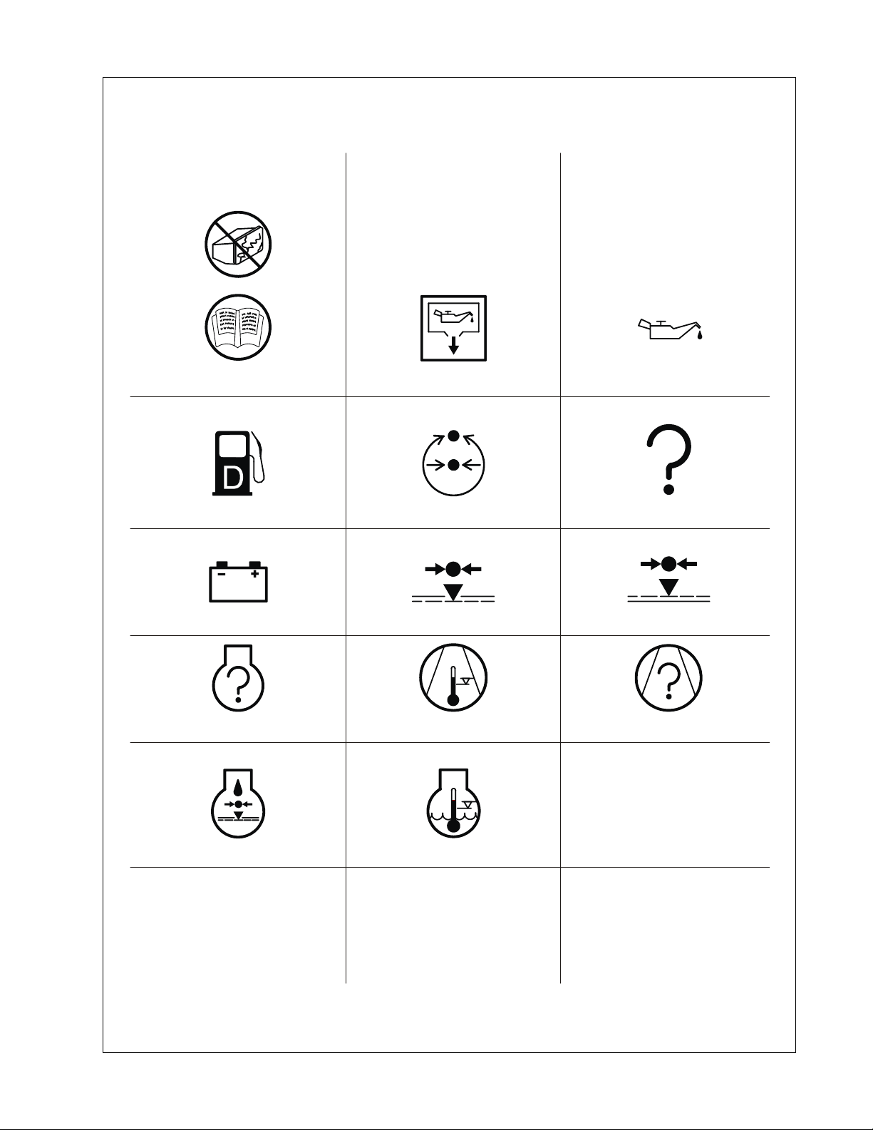
Safety Operation & Maintenance Manual
Replace any cracked protective shield Oil drain
Fuel level / point
Battery charging condition
Engine malfunction
Pressure control Malfunction
Low pressure
High Compressor Temperature
Engine Oil
High pressure
Compressor malfunction
Low engine oil pressure
Engine high temperature
27

Operation & Maintenance Manual Safety
28

Noise Emission
29

Operation & Maintenance Manual Noise Emission
Noise Emission
This section pertains only to compressors distributed within the United States.
!
WARNING
TAMPERING WITH NOISE CONTROL SYSTEM PROHIBITED
Federal law prohibits the following acts or the causing thereof:
(1) The removal or rendering inoperative by any persons, other than for purposes of
maintenance, repair, or replacement, of any device or element of design incorpo rated into any
new compressor for the purpose of noise control prior to its sale or delivery to the ultimate
purchaser or while it is in use; or (2) the use of the compressor after such device or element
of design has been removed or rendered inoperative by any person.
Among those acts included in the prohibition against tampering are these:
1. Removal or rendering inoperative any of the following:
a. the engine exhaust system or parts thereof
b. the air intake system or parts thereof
c. enclosure or parts thereof
2. Removal of any of the following:
a. fan shroud
b. vibration mounts
c. sound absorption material
3. Operation of the compressor with any of the enclosure doors open.
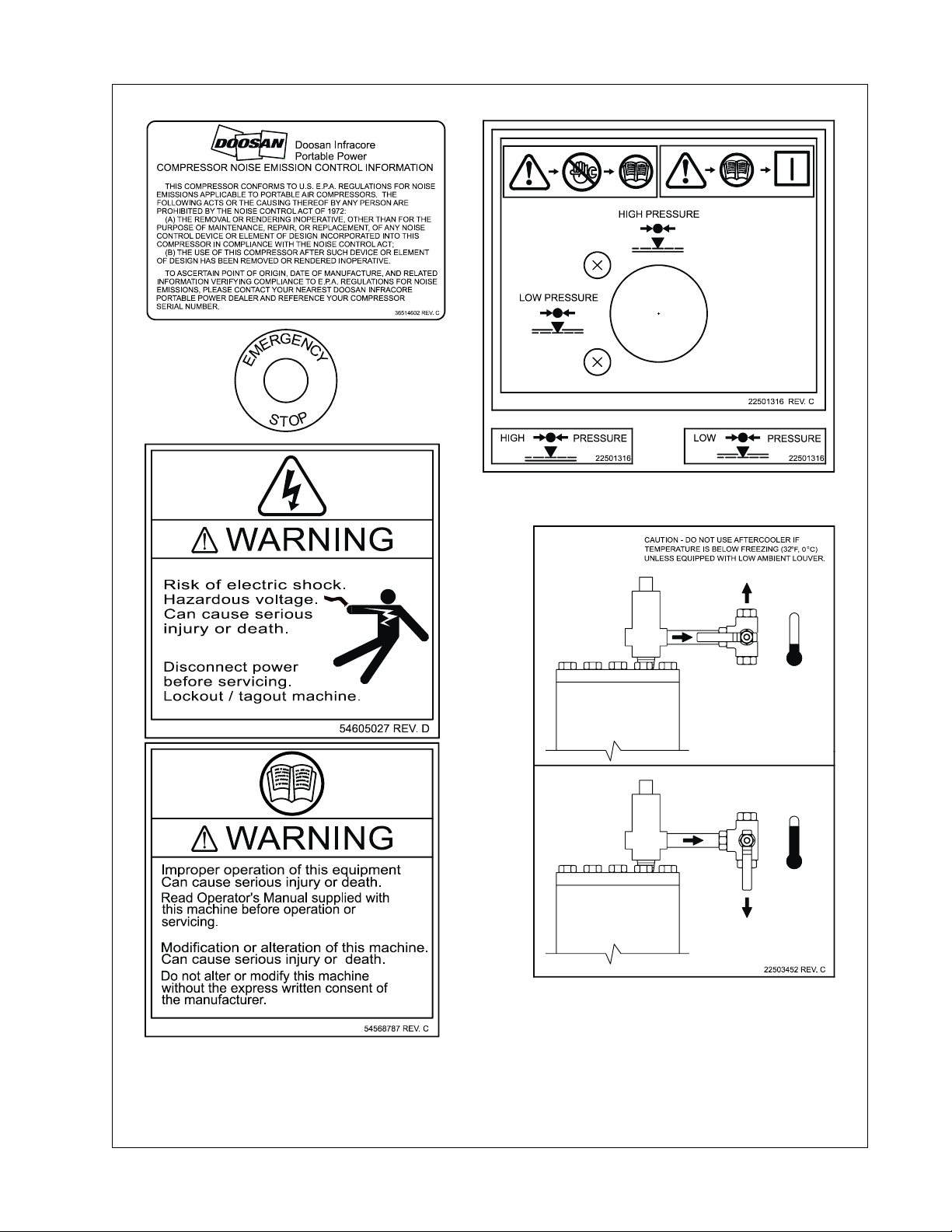
Compressor Noise Emission Control Information
A. The removal or rendering inoperative, other than for the purpose of
maintenance, repair, or replacement of any noise control device or element of
design incorporated into this compressor in compliance with the noise control
act;
B. The use of this compressor after such device or element of design has been
removed or rendered inoperative.
NOTE: the above information applies only to compressors that are built
in compliance with the U.S. Environmental Protection Agency.
Portable Power reserves the right to make changes or add improvements without notice and
without incurring any obligation to make such changes or add such improvements to products
sold previously.
The Purchaser is urged to include the above provisions in any agreement for any resale of this
compressor.
30

Noise Emission Operation & Maintenance Manual
Maintenance Log
COMPRESSOR MODEL_________________________
SERIAL NO. __________________________________
USER UNIT NO. _______________________________
UNIT IDENTIFICATION
Engine Make & Model:_________________
Serial No.:__________________________ __________________________________
Purchaser or Owner:__________________ __________________________________
Address: ___________________________ Date Purchased:_____________________
The Noise Control Act of 1972 (86 Stat. 1234) prohibits tampering with the noise control
system of any compressor manufactured and sold under the above regulations, specifically
the following acts or the causing thereof:
(1) the removal or rendering inoperative by any persons, other than for purposes of
maintenance, repair, or replacement, of any device or element of design in corporated into new
compressor for the purpose of noise control prior to its sale or delivery to the ultimate
purchaser or while it is in use; or (2) the use of the compressor after such device or element
of design has been removed or rendered inoperative by any person.
DEALER OR DISTRIBUTOR FROM
WHOM PURCHASED:
Noise Emission Warranty
The manufacturer warrants to the ultimate purchaser and each subsequent purchaser that this
air compressor was designed, built and equipped to conform at the time of sale to the first retail
purchaser, with all applicable U.S. EPA Noise Control Regulations.
This warranty is not limited to any particular part, componen t, or system of the air compressor.
Defects in the design, assembly or in any part, component, or system of the compressor
which, at the time of sale to the first retail purchaser, caused noise emissions to exceed
Federal Standards are covered by this warranty for the life of air compressor.(40CFR204.58-1)
31

Operation & Maintenance Manual Noise Emission
Introduction
The compressor for which this Maintenance Log is provided conforms to U.S. E.P.A.
Regulations for Noise Emissions, applicable to Portable Air Compressors.
The purpose of this book is to provide (1) the Maintenance Performance Schedule for all
required noise emission controls and (2) space so that the purchaser or owner can record what
maintenance was done, by whom, where and when. The Maintenance Schedule and detailed
instructions on the maintenance items are given on following page.
Maintenance Schedule
ITEM AREA PERIOD
A. Compressed Air Leaks As Detected
B. Safety and Control Systems As Detected
C. Acoustic Materials Daily
D. Fasteners 100 hours
E. Enclosure Panels 100 hours
F. Air Intake & Engine Exhaust 100 hours
G. Cooling Systems 250 hours
H. Isolation Mounts 250 hours
I. Engine Operation See Operator’s Manual
J. Fuels & Lubricants See Operator’s Manual
A. Compressed Air Leaks
Correct all compressed air leaks during the first shutdown period after discovery. If severe
enough to cause serious noise problems and efficiency loss, shut down immediately and
correct the leak(s).
B. Safety and Control Systems
Repair or replace all safety and control systems or circuits as malfunction occurs. No
compressor should be operated with either system bypassed, disabled, or nonfunctional.
C. Acoustic Materials
In daily inspections, observe these materials. Maintain all acoustic material as nearly as
possible in its original condition. Repair or replace all sections that have: 1) sustained damage,
2) have partially separated from panels to which they were attached, 3) are missing, or have
otherwise deteriorated due to severe operating or storage conditions.
32

Noise Emission Operation & Maintenance Manual
D. Fasteners
All fasteners such as hinges, nuts, bolts, clamps, screws, rivets, and latches should be
inspected for looseness after each 100 hours of operation. They should be retightened,
repaired, or if missing, replaced immediately to prevent subsequent damage and noise
emission increase.
E. Enclosure Panels
Enclosure panels should be inspected at 100 hour operational intervals. All panels that are
warped, punctured, torn, or otherwise deformed, such that their noise containment function is
reduced, should be repaired or replaced before the next operation interval. Doors, access
panels, and hatch closures especially, should be checked and adjusted at this time to ensure
continuous seating between gasket or acoustic material and the mating frame.
F. Air Intake and Engine Exhaust
Engine and compressor air intake and engine exhaust systems should be inspected after each
100 hours of operation for loose, damaged, or deteriorated components. Repairs or
replacements should be made before the next period of use.
G. Cooling Systems
All components of the cooling system for engine water and compressor oil shou ld be inspected
every 250 hours of use. Any discrepancies found should be corrected before placing the
compressor back in operation. Unrestricted airflow over the radiator and oil cooler must be
maintained at all times during operation.
H. Isolation Mounts
Engine/airend isolation mounts should be inspected after each 250 hours of operation. Those
mounts with cracks or splits in the molded rubber or with bent or broken bolts due to operation
or storage in severe environments should be replaced with equivalent parts.
I. Engine Operation
Inspect and maintain engine condition and operation as recommended in the manuals
supplied by the engine manufacturer.
J. Fuels and Lubricants
Use only the types and grades of fuels and lubricants recommended in the Operator and
Maintenance Manual and Engine Manual.
33

Operation & Maintenance Manual Noise Emission
MAINTENANCE RECORD FOR NOISE EMISSION CONTROL AND EXTENDED WARRANTY
ITEM NO.
DESCRIPTION OF WORK HOURMETER
READING
MAINT/ INSPECT
DATE
LOCATION
CITY/ STATE
WORK DONE
BY (NAME)
34

General Data
35

Operating & Maintenance Manual General Data
General Data Information
MODEL
COMPRESSOR
Air Delivery - cfm (m
Rated Operating Pressure -
psi (ba r)
Safety Valve Setting - psi
(bar)
ENGINE
Manufacturer Cummins
Model QSB 6.7
Rated Power at Full Load
Speed - hp (kw)
Full Load Speed - rpm 2200 1950
Idle Speed - rpm 1500
Idle Speed (warm-up) - rpm 1600
3
/min)
P600WCU-
T4i
600 (170) 525 (14.9)
100 (6.9) 125 (8.6)
200 (13.8)
XP525WCU-
T4i
HP450WCU-
450 (12.7) 400 (11.3)
150 (10.3) 200 (13.8)
173 (129) @ 2200 RPM
VHP400WC
T4i
U-T4i
250 (17.2)
2200 1950
Electrical System 24V
FLUID CAPACITIES - U.S. Gallons (liters)
Compressor Oil 9.5 (36)
Engine Oil, including filter 4.6 (17.5)
Engine Coolant 7.0 (26.5)
Fuel Tank 73 (276)
AMBIENT TEMPERATURE RANGE
With Standard Features 10°F(-12°C) to 120°F (49°C)
With Required Options -10°F(-23°C) to 120°F (49°C)
With Aftercooler or IQ System 32°F (0°C) to 110°F (43°C)
OUT-OF-LEVEL
Out-Of-Level Operating Limit 15°
36

General Data Operating & Maintenance Manual
MEASUREMENTS/WEIGHTS
Overall Length - feet (meters) (incl.
bumper)
Overall Height - feet (meters) 6.7 (2.0)
Overall Width - feet (meters) 6.5 (1.98)
Operating Weight, with fuel - lb (kg) 4700 (2132)
Shipping Weight, less fuel - lb (kg) 4178 (1895)
RUNNING GEAR
Tire Size ST235/80R16
Tire Inflation Pressure - psi (bar) 65 (4.5)
Maximum Towing Speed - mph (km/hr) 65 (105)
!
CAUTION
Any departure from the specifications may make this equipment unsafe.
14.8 (4.5)
37

Operating & Maintenance Manual General Data
38

Operating Instructions
39

Operating & Maintenance Manual Operating Instructions
Control Panel
Control/Gauge Panel
1. Air Pressure Gauge: Indicates pressure (PSI) in the separator tank
2. Engine Tachometer: Indicates engine speed (RPM).
3. Compressor Temperature Gauge: Indicates airend discharge temperature.
4. Engine Coolant Temperature Gauge: Indicates engine coolant temperature.
5. Fuel Level Gauge: Indicates level of fuel in tank.
6. Engine Oil Pressure Gauge: Indicates engine oil pressure (PSI).
7. MidPort Displays compressor operating parameters and diagnostic codes.
8. Main Power Button: St art and Shutdown compressor control system and gauge
panel.
9. KeyPad: Used to start and shutdown the compressor.
40

Operating Instructions Operating & Maintenance Manual
STOP: Shutdown the compressor.
START: Initiates engine cranking.
SERVICE AIR: Allows operator to load compressor after warm-up.
HI PRESSURE: Allows operator to switch to high pressure mode.
LO PRESSURE: Allows operator to switch to low pressure mode.
UP: Pressing and releasing the UP Button scrolls up through parameter lists and
menu choices or increases a value one item/unit at a time. Pressing and holding
the UP Button continuously scrolls up through parameter lists, menu choices, or
increases a value until the end of the parameter list, menu choices, or maximum
parameter value is reached.
DOWN: The DOWN Bu tton functions identical to the UP Button with the exception
that its direction for all displays, menu choices, and values is down or decreasing.
ENTER: Pressing and releasing this button provides enter functionality when the
display requires you to choose a menu item, parameter selection, or value input.
Pressing and holding this switch for approximately three seconds while any of the
Main Screens are displayed brings up the Main Menu. Pressing the ENTER Button
after an alert or fault has been displayed acknowledges the message and the
display unit returns to the Default Screen.
41

Operating & Maintenance Manual Operating Instructions
FAULT AND ALERT
If a FAULT occurs, the display unit will display the SPN, FMI, OC, and description for Engine
Fault or the CPR Code and Description for Compressor Error. An engine fault will be displayed
only when the engine is shutdown. The Fault has to be acknowledged by the user by pressing
the ENTER Button. The unit does not time out in the fault display. After 60 seconds, if the Fault
is still active, the fault display will appear again on the screen and will remain until
acknowledged by the user. This will continue to occur as long as the Fault is active.
See Figure 1.
Figure 1
When present, an ALERT with the number of alert conditions will popup on the screen, the
user will press the UP or DOWN Button to display the alert, or press the ENTER Button to
acknowledge an alert has occurred. If there are multiple alerts, pressing the DOWN Button will
scroll through the various alerts. All Faults and Alerts will be displayed until the engine shuts
down and then the most severe Fault will be displayed as a Fault. Pre ssing the ENTER Button
after the Alert has been displayed, acknowledges the message and the d isplay unit returns to
the Default Screen of Engine Hours. See Figure 2.
Figure 2
42

Operating Instructions Operating & Maintenance Manual
SERVICE INTERVAL
Service will popup on the screen after one of the two hour service channels has decremented
to 5 hours. The user will press the UP or DOWN Button to display the service channels or
press the ENTER Button to acknowledge a service has occurred. Pre ssing the ENTER Button
after the service channels have been displayed, acknowledges the message and the display
unit returns to the default screen. If service is between 5 and 0 hours or it remains at 0 hours,
the SERVICE DUE display will appear every hour. To disable, the user can reset the hours to
the OFF position by decreasing the value to OFF. See Figure 3.
Figure 3
The service intervals can be changed by pressing the ENTER Button while on the default
screen that displays the engine hours. Using the UP or DOWN Buttons to highlight the desired
interval and press the ENTER Button to select. Use the UP and DOWN Buttons to increase or
decrease the number of hours. Hours will decrement with every hour on the engine. Use the
DOWN Button to highlight the Main Screen menu item and press the ENTER Button to return
to the Default Screen of Engine Hours. See Figure 4.
Figure 4
43

Operating & Maintenance Manual Operating Instructions
LANGUAGES AND UNITS
The MidPort is user configured to display in English, Spanish, or French languages and in
either English or Metric units. The Language and Display units can be changed by accessing
the Setup Menu. To access the Setup Menu, press and hold the ENTER Button while the
Default Screen of Engine Hours is displayed until the Main Menu appears. Scroll to the Setup
option using the DOWN Button then press the ENTER Butto n. Use the DOWN or UP Buttons
to highlight the chosen unit and PRESS the ENTER Button to select. To return to the Default
Screen of Engine Hours, use the DOWN Button to highlight the Main Screen menu item and
press the ENTER Button. See Figure 5.
Figure 5
44

Operating Instructions Operating & Maintenance Manual
QUICKVIEW SCREENS (ENGINE AND COMPRESSOR PARAMETERS)
The Quick View Screens allow for easy viewing of up to 18 commonly used parameters by
pressing the UP and DOWN Buttons. Pressing the UP and DOWN Buttons continuously loops
through the Quick View Screens (i.e., when the last screen is reached pressing the DOWN
Button displays the first screen and vice versa).
Figure 6
Note 1: Only the parameters that are available from the engine or compressor will be
displayed.
Note 2: Unit times out after 3 minutes of inactivity and returns to the Default Screen of Engine
Hours.
Note 3: Pressing the Enter Button while viewing a Quickview Screen will return to the Default
Screen of Engine Hours.
45

Operating & Maintenance Manual Operating Instructions
DISPLAY SETUP
The Display Menu functions give users the ability to configure the LCD. Options for configuring
the display include intensity, contrast, and viewing mode. To access the Display Menu:
1. Press and hold the ENTER Button while the Default Screen of Engine Hours is
displayed until the Main Menu appears.
2. Scroll to the Setup option using the DOWN Button and press the ENTER
Button.
3. Scroll to the Display option using the DOWN Button and press the ENTER
Button.
4. Use the DOWN or UP Buttons to highlight and the ENTER Button to select the
desired display setting. See Figure 7.
5. To return to the Default Screen of Engine Hours, use the DOWN Button to
highlight the Main Screen menu item and press the ENTER Button. Note: Main
Screen menu item returns the user back to the Default Screen of Engine Hours.
Figure 7
46

Operating Instructions Operating & Maintenance Manual
AUTO POWER OFF
The Compressor Control System has a power save feature designed to prevent drain on the
batteries when the compressor engine is not running. If the Control Panel is powered ON and
the engine has not run for 3 minutes (above 45°F (7°C) or 15 minutes at or below 45 °F (7° C)),
the control system will automatically power OFF. Power can be restored by pressing the Main
Power Button.
In the event of a fault, this feature is not active and the power will remain on until the fault has
been acknowledged or the control system is manually powered off.
WAIT TO START
When the Main Power Button is pressed, the display will initialize and the Wait to Start
message will be displayed. While the Wait to Start message is displayed, the engine will
receive heat from the intake heater if required. It is best to start the engine immediately after
the Wait to Start message changes to Engine Total Hours.
Lifting
The central lifting bail allows the compressor to be lifted from a single point. Use hoist or crane
capable of lifting compressor weight (See General Data).
!
WARNING
Falling off the compressor can cause serious injury or death. Use ladder
and handholds to access lifting bail.
Before Towing
Ensure the tires, wheels and running gear are in good condition and secure.
High Speed Running Gear
• Use jack to raise or lower drawbar.
• Use tow vehicle whose towing capacity is greater than the weight of the compressor
(See General Data).
• Do not tow the compressor in excess of the maximum towing speed (See General
Data).
• Place wheel chocks under tires and/or set parking brake before disconnecting from
towing vehicle.
• When raising or lowering drawbar, always stand to one side.
47

Operating & Maintenance Manual Operating Instructions
Setting Up
Place the compressor in an open, well-ventilated area. Ensure sufficient clearance for
ventilation and exhaust requirements. Adequate clearance needs to be allowed around and
above the compressor to permit safe access for specified maintenance tasks.
Position as level as possible. Do not exceed the out-of-level operating limit (See General
Data).
When the compressor is to be operated out-of-level, it is imp ortant: (1) to ke ep the engine oil
level near the high level mark (with the compressor level), and (2) to have the compressor oil
level gauge show no more than mid-scale (with the compressor running at full load). Do not
overfill either the engine oil or the compressor oil.
Ensure the compressor is positioned securely and on a stable foundation. Any risk of
movement should be removed by suitable means, especially to avoid strain on air discharge
piping.
Chock wheels and/or set parking brake.
Ensure all transport and packing materials are removed.
Compressor Mounting
Portable compressors, which are modified to remove the running gear and mount the
compressor directly to trailers, truck beds, or frames, etc. may experience failure of the
enclosure, frame, and/or other components. It is necessary to isolate the compressor package
from the carrier base with a flexible mounting system. Such a system must also prevent
detachment of the package from the carrier base in the event the isolators fail. Contact your
Portable Power representative for flexible mounting kits.
Warranty does not cover failures attributable to mounting of the compressor package to the
carrier base unless it is a Portable Power provided system.
Service Air Connection(s)
!
WARNING
All air pressure equipment installed in or connected to the compressor
must have safe working pressure ratings of at least the safety valve
setting and materials compatible with the compressor oil (Refer to the
General Data).
48

Operating Instructions Operating & Maintenance Manual
!
WARNING
Do not connect the air discharge on this compressor onto a common
header with any other unit of any description, or any other source of
compressed air, without first ensuring a check-valve is used between the
header and the compressor. If this compressor is connected in parallel
with another compressor of higher discharge pressure and capacity a
safety hazard could occur in a back-flow condition.
!
WARNING
Unrestricted air flow from a hose will result in a whipping motion of the
hose which can cause serious injury or death. A safety device must be
attached to the hose at the source of supply to reduce pressure in case
of hose failure or other sudden pressure release. Reference: OSHA
regulation 29 CFR Section 1926.302 (b).
Air Hose Restraint Installation
Safety devices such as hose restraints (whipchecks) must be used to pre vent hose whipping
if a connection fails. Whipchecks are to be constructed of woven stainless steel, galvanized
steel wire rope, or chain with a minimum strength adequate for the supplied pressure and hose
diameter. Whipchecks must be fastened to suitable mounting points or shackles.
The mounts and/or shackles are to be of the same or greater strength as the whipchecks. An
engineer should be consulted about suitability of whipchecks, mounts, mounting points,
shackles, and fittings as well as strength rating of materials. Whipchecks must be used at the
hose origination, termination, and each hose to hose connection.
Hoses can fail in areas other than at connecting points and require daily inspection of the
hoses for:
• Cuts, cracks, or kinks
• Weakened clamps due to rust and corrosion
• Damaged connections
• Deformity
• Incorrect or incompatible components or fittings
• Any visual damage
Hoses must be selected that are rated for the application as to the maximum pressure and
temperature to be encountered as well as compatible with the materials being conveyed inside
the hose. Hoses must be compatible with the compressor oil.
49

Operating & Maintenance Manual Operating Instructions
Before Starting
Open Manual Blowdown Valve to ensure the separator tank has been vented of all pressure.
Close the valve before starting. Inspect the complete installation including remote fuel lines (if
any) and air hose routing and connections. Check battery for proper connections and
condition.
!
WARNING
Combustible gas can cause severe burns, blindness, or death. Keep
sparks and open flame away from battery.
Check the compressor oil level. Maintain the oil level between bottom and midway of the sight
glass on the separator tank.
Check engine oil level. The proper level is labeled on the engine dipstick. Add oil when
required. Do not overfill.
!
CAUTION
Exercise extreme caution when using an external method to jumpstart a
unit. Verify the electrical systems on the weak battery system and the
external jump system are the same voltage type system, 12VDC or
24VDC. Connect the Positive (+) terminal of the external system to the
Positive (+) terminal on the weak system. Connect the Negative (-)
terminal of the external system to the Negative (-) terminal of the weak
system. Always disconnect the two systems in reverse order.
!
WARNING
Do not remove the pressure cap from a HOT engine radiator. The sudden
release of pressure from a heated cooling system can result in a loss of
coolant and possible severe personal injury.
!
WARNING
Hot pressurized fluid can cause serious burns. Do not open radiator while
hot.
Check coolant to ensure coolant level is at or above minimum level when the engine is cold.
Check engine coolant level at radiator pressure cap. Add coolant as required. Ensure pressure
cap is installed properly and tightened.
50

Operating Instructions Operating & Maintenance Manual
NOTICE
If the appropriate mixture of antifreeze is not used during freezing
temperatures, failure to drain the engine may cause costly engine
damage. Never use water only, as corrosion inhibitors are required in
engine coolant fluid.
!
CAUTION
No smoking, sparks, or open flame near fuel.
Check the fuel level and add fuel as necessary. Ultra-low sulfur diesel fuel (ULSD), with a
maximum sulfur content of 15 ppm is required. If ultra-low sulfur diesel is not used, the engine
could possibly not meet emissions regulations and the engine or aftertreatment system may
be damaged. Refer to the Engine Operator Manual for fuel specifications.
NOTICE
To minimize condensation (water) in the fuel tank, it is recommended to
fill the tank at the end of each day.
NOTE: Compressor will not allow engine starting if the fuel level is below
the minimum fuel shut off level.
!
WARNING
Compressor produces loud noise with doors open. Extended exposure to
loud noise can cause hearing loss. Wear hearing protection when doors
or valve(s) are open.
Close the doors to maintain a cooling air path and to avoid recirculation of hot air. This will
maximize the life of the engine and compressor and protect the hearing of surrounding
personnel.
Ensure no one is IN or ON the compressor.
Ensure that the location of the Emergency Stop Button (if equipped) is known and recognized
by its markings. Ensure that it is functioning correctly and that the method of operation is
known.
51

Operating & Maintenance Manual Operating Instructions
!
WARNING
Ensure that the access panels for heat exchanger cleaning are closed
and secure before starting the compressor. Rotating fan blades can
cause serious injury or death. Do not operate without all guards in place.
Starting
!
CAUTION
Do not use ether or any other starting fluid. Starting fluids can cause an
explosion, fire, and severe engine damage. The engine is equipped with
an electric heater starting aid.
NOTICE
This compressor is equipped with a battery disconnect switch which
disconnects power for long term storage. The switch is located on the
fuel tank side.
This switch must be in the ON position to provide power to the Control
Panel for starting the compressor.
1. Press the Main Power Button.
2. When the Wait To Start message on the MidPort changes to Total Engine
Hours =, press and release Green Start Button .
3. Engine will crank until engine starts or engine starting time limit is reached. The
first Green light on the Start Button will illuminate.
4. If engine fails to start, press Main Power Button to remove power from
engine, then repeat steps 1-3.
5. When engine starts, the first two lights on the Start Button will illuminate.
6. Wait for Engine Temperature to reach 150°F (65°C). Press Service Air
Button. The third light on the Start Button will illuminate.
7. The compressor will start in the Low Pressure Mode and the Low Pressure
Light will be illuminated on the Low Pressure Button.
8. To change to the High Pressure Mode, press the High Pressure Button. Three
lights on the button will illuminate.
52

Operating Instructions Operating & Maintenance Manual
!
CAUTION
To ensure an adequate flow of oil to the airend, never allow the discharge
pressure to fall below 50 psi.
Normal Operation
The operator may observe and monitor operating parameters using the MidPort and gauges.
In the event the compressor controller detects a parameter outside normal operating limits, the
compressor will alert and/or shutdown, and display a diagnostic code.
In the event the compressor controller detects a parameter at a dangerously high or low level,
the compressor will be automatically shut down with the cause of the shutdown shown on the
MidPort.
Two Pressure Modes of Operation
The compressor is capable of operating at two pressure modes:
1. The Low Pressure Mode is activated by pressing the Lo Pressure Button. In this
mode, the compressor will regulate according to the air demand, between 0 and rated air
delivery (See General Data) at the lower regulated set pressure (See General Data). The
regulated set pressure of this mode can be regulated as low as 80 psi.
2. The High Pressure Mode is activated by pressing the Hi Pressure Button. In High
Pressure Mode, the compressor will regulate according to air demand, between 0 and rated
air delivery (See General Data) at the higher regulated set pressure (See General Data). The
regulated set pressure of this mode can be regulated as low as 80 psi.
The mode of the compressor can be changed between the Low and High at anytime. Engine
speed will be lower at the HI Pressure Mode setting.
Operation - Loaded
Assume engine has been started and is running in the unload state at idle speed. If there is air
demand (pressure falls below the load point pressure), compressor will load at idle speed by
opening the inlet valve. As air demand rises and falls, engine speed is controlled between idle
speed and full load speed to match the required flow while maintaining load point pressure.
Operation - Unloaded
If there is no air demand at idle speed (pressure rises above the unload point pressure), the
compressor will unload by closing the inlet valve. The compressor then runs at idle speed
unloaded with no air delivery. If air demand increases (pressure falls below the load point
pressure), the compressor reloads to meet the required air demand.
53

Operating & Maintenance Manual Operating Instructions
Shutdown
1. Close the Service Valve.
2. Allow the engine to idle for 3 minutes to cool down.
3. Press the Red Stop Button.
4. Press the Main Power Button xxxxxxxxx when use of the compressor is not
needed.
Note: Until Main Power Button is pressed, the gauges can be read and the MidPort
can be navigated using the UP, DOWN, and ENTER Buttons.
5. If the Main Power Button is not pressed within 3 minutes (if ambient
temperature is above 45°F (7°C) or 15 minutes if ambient temperature is 45°F
(7°C) or below of the keypad use the compressor will automatically shut off.
NOTICE
Failure to allow turbocharger cool down prior to stopping can cause
turbocharger damage.
NOTICE
This compressor is equipped with a battery disconnect switch which
disconnects power for long term storage. The switch is located on the
fuel tank side.
Do not use the battery disconnect switch for normal stopping. Wait 1
minute after stopping engine before turning the battery disconnect
switch to the OFF position.
!
CAUTION
Use the Emergency Stop, if equipped, only for emergency conditions. Do
not use for normal stopping. Emergency Stop must be reset before
starting can be accomplished.
54

Operating Instructions Operating & Maintenance Manual
NOTICE
Once the engine stops, the Automatic Blowdown Valve will relieve
pressure from the separator tank. If the Automatic Blowdown Valve fails
to operate, pressure must be relieved from the system by means of the
Manual Blowdown Valve.
!
WARNING
Pressure will remain in the system between the Minimum Pressure Valve
and the Service Valve after shutdown and operation of the Automatic
Blowdown Valve. This pressure must be relieved by disconnecting any
downstream equipment and opening the Discharge Valve to atmosphere.
!
CAUTION
Never allow the compressor to sit stopped with pressure in the separator
tank or piping. As a precaution, open the Service Valve.
Decommissioning
When the compressor is to be permanently decommissioned or dismantled, it is important to
ensure that all hazard risk are either eliminated or recepient of the compressor notified. In
particular:
• Do not destroy batteries or components containing asbestos without containing the
materials safely.
• Do not dispose of any pressure vessel that is not clearly marked with its relevant data
plate information or rendered unusable by drilling, cutting, etc.
• Do not allow lubricants or coolants to be released into land surfaces, water, or drains.
• Do not dispose of a complete compressor without documentation relating to
instructions for its use.
55

Operating & Maintenance Manual Operating Instructions
56

Maintenance
57

Operation & Maintenance Manual Maintenance
General Information
This section refers to the various components which require periodic maintenance and
replacement.
The Maintenance Schedule indicates the various components' descriptions and the intervals
when maintenance has to take place. Fluid capacities can be found in the General Data
Section of this manual. For any specification or specific requirement on service or pre ventative
maintenance for the engine, refer to the Engine Manual.
Compressed air can be dangerous if incorrectly handled. Review all maintenance precautions
listed below before attempting any maintenance work on the compressor.
Maintenance Precautions
Prior to attempting any maintenance work, ensure:
1. All pressure is vented from the system and the compressor cannot be started
accidentally.
2. If the Automatic Blowdown Valve fails to operate, pressure must be gradually
relieved by operating the Manual Blowdown Valve.
3. The discharge pipe/manifold area is depressurized by opening the discharge
valve while keeping clea r of any air flow.
4. Maintenance personnel are adequately trained, competent, and have read t he
Operation and Maintenance Manual.
!
WARNING
Pressure will remain in the system between the Minimum Pressure Valve
and the Service Valve after shutdown and operation of the Automatic
Blowdown Valve. This pressure must be relieved by disconnecting any
downstream equipment and opening the discharge valve to atmosphere.
Prior to opening or removing panels or covers inside a compressor, ensure:
1. Anyone entering the compressor is aware of the reduced level of protection and
the additional hazards, including hot surfaces and intermittently moving parts.
2. The compressor cannot be started. Post warning signs and/or fit anti-start
devices.
3. Battery cables are disconnected.
58

Maintenance Operation & Maintenance Manual
Prior to attempting any maintenance work on a running compressor, ensure:
1. The work carried out is limited to only those tasks which require the compressor
to run.
2. The work carried out with safety protection devices disabled or removed is
limited to only those tasks which require the compressor to be running with
safety protection devices disabled or removed.
3. All hazards present are known (e.g. pressurized components, electrically live
components, removed panels, covers and guards, extreme temperatures,
inflow and outflow of air, intermittently moving parts, safety valve discharge).
4. Appropriate personal protective equipment is worn.
5. Loose clothing, jewelry, long hair etc. is made safe.
6. Warning signs indicating that Maintenance Work is in Progress are posted in a
position that can be clearly seen.
Upon completion of maintenance task and prior to returning the compressor into
service, ensure:
1. The compressor is suitably tested.
2. All guards and safety protection devices are refitted.
3. All panels are replaced, canopy and doors closed.
4. Hazardous materials are effectively contained and disposed of.
NOTICE
The maintenance schedule in this manual describes the service intervals
that should be followed for normal applications of this compressor. This
page may be reproduced and used as a checklist by service personnel.
In more severe applications (i.e., sandblasting, quarry drilling, well
drilling, and oil and gas drilling) more frequent service intervals will be
required to ensure long component life.
Dust and dirt, high humidity, and high temperatures will affect lubricant
life and service intervals for components such as inlet air filters, oil
separation elements, and oil filters.
59

Operation & Maintenance Manual Maintenance
Maintenance Schedule
Initial
500 miles
/850 km
Compressor Oil Level C
Engine Oil Level C
*Radiator Coolant Level C
Gauges/Lamps C
*Air Cleaner Service Indicators C
Fuel Tank (Fill at end of day) C D
*Fuel/Water Separator Drain C
Oil Leaks C
Fuel Leaks C
Drain Water From Fuel Filters D
Coolant Leaks C
Radiator Filler Cap C
*Emergency Stop T
*Lubricator (Fill) C
Daily Weekly Monthly
Every 3
Months
500 hrs.
Every 6
Months
1000 hrs.
Every 12
Months
2000 hrs.
Air Cleaner Precleaner Dumps C
Fan/Alternator Belts C
Battery Connections/Electrolyte C
Hoses (Oil, Air, Intake, etc.) C
Automatic Shutdown System C
Air Cleaner System C
Compressor Oil Cooler Exterior C
*Engine Rad/Oil Cooler Exterior C
Engine Charge Air Cooler Exterior C
*Aftercooler Exterior C
Safety Valve C
Fasteners, Guards C
*Disregard if not appropriate for this particular compressor. D = Drain
(1) or 3000 miles/5000km whichever is the sooner G = Grease W I = or when indicated if earlier.
C = Check (adjust, clean or replace as necessary) R = Replace
CBT = Check before towing. T = Test
CR = Check and report
60

Maintenance Operation & Maintenance Manual
Initial
500 miles
/850 km
Air Cleaner Elements R/WI
*Fuel/Water Separator Element R
Fuel Filter Element R
Engine Oil Change R
Engine Oil Filter R
*Engine Coolant Cond. Element R
Compressor Oil Filter Element R
Compressor Oil R
Oil Separator Element R
Separator Tank Exterior (2) CR
*Engine Coolant C R
Engine Crankcase Breather
Element
*Water Pump Grease. G
Shutdown Switch Settings T
Daily Weekly Monthly
Every
6Months
500 hrs.
Every 12
Months
1000 hrs
R
Every 48
Months
5000 hrs
Scavenge Orifice & Related Parts C
Scavenge Line C
*Valve Clearance Check C
*Feed Pump Strainer Cleaning C
*Injection Nozzle Check C
*Disregard if not appropriate for this particular compressor. D = Drain
(1) or 3000 miles/5000km whichever is the sooner G = Grease
(2) or as defined by local or national legislation R = Replace
C = Check (adjust, clean or replace as necessary) T = Test
CBT = Check before towing. W I = or when indicated if earlier.
CR = Check and report
61

Operation & Maintenance Manual Maintenance
Initial
500 miles
/850 km
*Brake linkage C C
*Brakes C C
*Lights (running, brake, & turn) CBT
*Pintle Eye Bolts CBT
*Tire Pressure and Condition C
*Wheel Lug Nuts C
*Running gear linkage G
*Running gear bolts(1) C
*Wheels (Bearings, Seals, etc.) CG
Daily Weekly Monthly
3 Months
500 hrs.
6 Months
1000 hrs
12
Months
2000 hrs
2 Yrs4 Yrs6 Yrs
Safety valve C
Hoses R
Separator tank (2) interior C
*Disregard if not appropriate for this particular compressor. D = Drain
(1) or 3000 miles/5000km whichever is the sooner G = Grease
(2) or as defined by local or national legislation R = Replace
C = Check (adjust, clean or replace as necessary) T = Test
CBT = Check before towing. W I = or when indicated if earlier.
CR = Check and report Refer to specific sections of the operator's manual for
more information.
62

Maintenance Operation & Maintenance Manual
Scavenge Line
The scavenge line runs from the combined orifice/check valve at drop tube in the separator
tank to the fitting located in the airend.
Check that the scavenge line and tube are clear of any obstruction. Refer to the Maintenance
Schedule for recommended servicing intervals. Any blockage will result in oil carryover into the
discharge air.
Compressor Oil Filter
Refer to the Maintenance Schedule for the recommended servicing intervals.
Removal
!
WARNING
Do not remove the filter(s) without first ensuring the compressor is shut
off and the system has been completely relieved of all air pressure. (Refer
to STOPPING in the OPERATING INSTRUCTIONS section of this manual).
Clean the exterior of the filter housing and remove the spin-on element.
lnspection
Inspect the oil filter head to be sure the gasket was removed with the oil filter element. Clean
the gasket seal area on the oil filter head.
!
CAUTION
If there is any indication of the formation of varnishes, shellacs, or
lacquers on the filter element, it is a warning that the compressor
lubricating and cooling oil has deteriorated and should be changed
immediately. Refer to LUBRICATION section.
NOTICE
Installing a new oil filter element when the old gasket remains on the filter
head will cause an oil leak and can cause property damage.
Reassembly
Clean the filter gasket contact area and install the new element. Tighten until the gasket makes
contact with the filter housing. Tighten an additional 1/2 to 3/4 of a revolution.
63

Operation & Maintenance Manual Maintenance
!
CAUTION
Start the compressor (refer to BEFORE STARTING and STARTING in the
OPERATING INSTRUCTIONS section of this manual) and check for
leakage before the compressor is put back into service.
Compressor Oil Separator Element
Refer to the Maintenance Schedule in this section for the recommended servicing intervals. If
the element has to be replaced, then proceed as follows:
Removal
!
WARNING
Do not remove the filter(s) without first ensuring the compressor is shut
off and the system has been completely relieved of all air pressure. (Refer
to STOPPING in the OPERATING INSTRUCTIONS section of this manual).
Disconnect all hoses and tubes from the separator tank cover plate. Remove the drop tube
from the separator tank cover plate and remove the cover plate. Remove the separator
element.
lnspection
Examine the separator element. Examine all hoses and tubes, and replace if necessary.
Reassembly
Thoroughly clean the orifice/drop tube and filter gasket contact area before reassembly. Install
the new element.
!
WARNING
DO NOT remove the staple from the anti-static gasket on the separator
element since it serves to ground any possible static build-up. DO NOT
use gasket sealant since this will affect electrical conductance.
64

Maintenance Operation & Maintenance Manual
Reposition the cover plate, taking care not to damage the gasket. Replace the cover plate
screws tightening in a criss-cross pattern to the recommended torque (refer to the torque
values in this section).
Reconnect all hoses and tubes to the separator tank cover plate.
Replace the compressor oil (refer to LUBRICATION section).
!
CAUTION
Start the compressor (refer to BEFORE STARTING and STARTING in the
OPERATING INSTRUCTIONS section of this manual) and check for
leakage before the compressor is put back into service.
Compressor Oil Cooler, Engine Radiator, and other Heat
Exchangers
When grease, oil, and dirt accumulate on the exterior surfaces of the heat exchangers, the
efficiency is impaired. It is recommended that the heat exchangers be cleaned per the
Maintenance Schedule in this manual by a jet of compressed air. This should remove any
accumulation of oil, grease, and dirt from the exterior cores of the cooler so the entire cooling
area can radiate heat into the air stream. Access doors are located on each side of the
compressor to provide access to aid in cleaning the heat exchangers.
!
WARNING
Ensure the heat exchanger access doors are closed and secure before
starting the engine.
!
WARNING
Hot engine coolant and steam can cause injury. When adding coolant or
antifreeze solution to the engine radiator, stop the engine and allow
radiator to cool prior to releasing the radiator pressure cap. Using a cloth
to protect the hand, slowly release the pressure cap, absorbing any
released fluid with the cloth. Do not remove the pressure cap until all
excess fluid is released and the engine cooling system fully
depressurized.
65

Operation & Maintenance Manual Maintenance
!
WARNING
Follow the instructions provided by the antifreeze supplier when adding
or draining the antifreeze solution. It is advisable to wear personal
protective equipment to prevent skin and/or eye contact with the
antifreeze solution.
Air Filter Elements
The air filter elements should be replaced regularly (refer to the Maintenance Schedule) or
when indicated on the Control Panel, whichever comes first. The aircleaner precleaner dumps
should be cleaned as indicated in the Maintenance Schedule (more frequently in dusty
operating conditions).
Removal
!
CAUTION
Never remove and replace element(s) when the compressor is running.
Clean the exterior of the filter housing and remove the filter element by following instructions
on the filter.
If the safety element is to be replaced, thoroughly clean the interior of the filter housing prior
to removing the safety element.
Inspection
Check for cracks, holes, or any other damage to the element by holding it up to a light source
or by passing a lamp inside.
!
CAUTION
If inspection reveals damage to the main element, the safety element
must be replaced.
Check the seal at the end of the element and replace if any sign of damage is evident.
Reassembly
Assemble the new element into the filter housing ensuring the seal seats properly. Secure
element following instructions on the filter.
Before restarting the compressor, ensure all clamps are tight.
66

Maintenance Operation & Maintenance Manual
Ventilation
Ensure air inlets and outlets are clear of debris etc.
Cooling Fan Drive
Every 3 months check to ensure fan drive mounting bolts to the engine have not loo sened. If,
for any reason, it becomes necessary to remove or re-tighten the mounting bolts, apply a good
grade of commercially available thread locking compound to the bolt threads and tighten to
23Nm (17 ft-lbF) of torque.
The fan belt(s) should be checked monthly for wear and correct tensioning.
This compressor is equipped with a variable speed fan clutch and requires no periodic
maintenance.
Fuel System
The fuel tank(s) should be filled daily or every eight hours. To minimize condensation in the
fuel tank(s), it is advisable to top up after the compressor is shut down or at the end of each
working day. Drain any sediment or condensate that may have accumulated in the tank(s).
Refer to Maintenance Schedule.
Fuel Filter Water Separator
The fuel filter water separator contains a filter element which should be replaced as required
by the Maintenance Schedule.
Charge Air Cooler Pipework
Foreign particles can damage the engine and turbocharger. Maintain internal cleanliness and
integrity of the air filtration, intake piping, and charge air cooler piping to help avoid damage.
Monthly inspect systems for leaks and that hoses, clamps, and connections are sealed. Check
for damaged or deteriorated components. Pay careful attention to keep the internal surfaces
clean, particularly when parts are removed for inspection or service.
Hoses
All components of the fuel, engine cooling, and air intake system should be checked monthly
to keep the engine at peak efficiency.
At the recommended intervals, (see the Maintenance Schedule), inspect all of the intake lines
to the air filter, and all flexible hoses used for air lines, oil lines, and fuel lines.
Every 3 months inspect all pipework for cracks, leaks, etc. and replace immediately if
damaged.
67

Operation & Maintenance Manual Maintenance
Electrical System
!
WARNING
Disconnect the battery cables before performing any maintenance or
service.
Check the security of electrical devices and sensors to ensure terminals and/or connectors are
tight. Loose connections may cause local hot spot oxidation.
When removing connectors from electrical devices and sensors, inspect the terminals to
ensure they have electrical grease on them. If electrical grease is not present or very minimal,
add a small amount of Doosan Part No. 22409114 Electrical Grease to the terminals.
Dirty and/or corroded electrical terminals can be cleaned using electrical contact cleaner.
Inspect the components and wiring for signs of overheating (i.e., discoloration, charring of
cables, deformation of parts, acrid smells, and blistered paint).
Battery
Keep the battery terminals and cable clamps clean and lightly coated with petroleum jelly to
prevent corrosion. The battery restraint should be kept tight enough to prevent the battery from
moving.
Pressure System
Regularly, it is necessary to inspect the external surfaces of the pressure system, from the
Airend through to the Service Valve(s) including hoses, tubes, tube fittings, and the separator
tank for visible signs of impact damage, excessive corrosion, abrasion, tightness, and chafing.
Any suspect parts should be replaced before the compressor is put back into service.
Tire Pressure
See the General Data Section of this manual.
Running Gear/Wheels
Check wheel nut torque 20 miles (30 kilometers) after refitting the wheels. Refer to Torque
Values later in this section.
Lifting jacks should only be used under the axle.
Bolts securing the running gear to the chassis should be checked for tightness (refer to the
Maintenance Schedule for frequency). Re-tighten where necessary. Refer to Torque Values
later in this section.
68

Maintenance Operation & Maintenance Manual
Lubrication
!
CAUTION
Always check the oil levels before a new compressor is put into service.
If, for any reason, the compressor oil has been drained, it must be re-filled with new oil before
putting into operation.
Engine Oil
The engine oil and oil filter element should be changed at the engine manufacturer's
recommended intervals. Refer to the Engine Operator Manual.
The Tier 4 engine in this compressor requires engine lubricating oil to ensure proper
Aftertreatment System operation and engine durability. Doosan Tier 4 Premium Engine Oil is
recommended. Refer to the Engine Operator Manual for engine oil specifications.
Compressor Oil
Refer to the Maintenance Schedule in this section for service intervals.
NOTE: If the compressor has been operating under adverse conditions or
has suffered long shutdown periods, more frequent service intervals will
be required.
!
WARNING
DO NOT, under any circumstances, remove any drain plugs or the oil filler
plug from the compressor lubricating and cooling system without first
ensuring the compressor is stopped and the system has been completely
relieved of all air pressure (refer to STOPPING in the Operating
Instructions Section of this manual).
Completely drain the separator tank, piping, and oil cooler by removing the drain plug(s) and
collecting the used oil in a suitable container.
Replace the drain plug(s) ensuring that each one is secure.
NOTE: If the oil is drained immediately after the compressor has been in operation,
most of the sediment will be in suspension and will drain more readily.
69

Operation & Maintenance Manual Maintenance
!
CAUTION
Some oil mixtures are incompatible and result in the formation of
varnishes, shellacs, or lacquers which may be insoluble. Refer to the
Portable Compressor Oil Chart.
Running Gear Wheel Bearings
Wheel bearings should be greased per the Maintenance Schedule in this manual. The type of
grease used should conform to specifications below:
Grease
Thickener Type Lithium Complex
Dropping Point 215°C (419°F) Minimum
Consistency NLGI No.2
Additives EP, Corrosion & Oxidation Inhibitors
Viscosity Index 80 Minimum
70

Maintenance Operation & Maintenance Manual
Pressure Regulator Adjusting Instructions
Low Pressure Regulator
Before Starting
1. Select Low Pressure Mode by pressing the LO Pressure Button.
2. At the Low Pressure Regulator, loosen the jam nut and turn screw counterclockwise until
tension is no longer felt at the screw. Turn screw clockwise one full turn.
3. If high pressure regulation needs adjustment, repeat Step 2 at High Pressure Regulator.
4. Close Service Valves.
After Starting Unit
5. Push the Service Air Button on the Control Panel. The unit should speed up and then u nload
(and drop back to IDLE). With the unit unloaded, turn the adjusting screw on the Low Pressure
Regulator clockwise until the discharge pressure gauge indicates 25 psi over the rated
pressure. Tighten the pressure regulator jam nut.
6. To adjust the high pressure regulation, repeat Step 5 on High Pressure Regulator except
adjust pressure at idle to 25 psi over the rated pressure while in High Pressure Mode.
Note: The High Pressure Regulator must be set at a higher pressure than the Low Pressure
Regulator.
High Pressure Regulator
71

Operation & Maintenance Manual Maintenance
Torque Values
TABLE 1 INCH FASTENERS
SAEJ249
SAEJ249
72

Maintenance Operation & Maintenance Manual
Note: Cooling Fan Drive Bolts (10.9 M8x1.25) should be torqued to 23Nm (17ft-lbF).
TABLE 3
TABLE 3
Wheel Torque Chart - Inch Wheel Torque Chart - Metric
1/2” lug nuts Torque (Ft-Lbs) Torque (N-m) Torque (ft-Lbs)
13” Wheel 80-90
15” Wheel 105-115 M12 Bolts 85-95 62-70
16” Wheel 105-115 M14 Bolts 145-155 107-115
16.5” Wheel 105-115 M16 Bolts 175-185 129-137
5/8” Lug Nuts
16” Wheel 190-210
17” Wheel 190-210
9/16” Clamp nuts/Demountable
Wheels
14.5” Wheel 105-115
WHEEL TORQUE CHART
M18 Bolts 205-215 151-159
73

Operation & Maintenance Manual Maintenance
74

Lubrication
75

Operation & Maintenance Manual Lubrication
General Information
Lubrication is an essential part of preventive maintenance, affecting to a great extent the
useful life of the compressor. Different lubricants are needed and some components require
more frequent lubrication than others. Therefore, it is important that th e instructions regarding
types of lubricants and the frequency of their application be explicitly followed. Periodic
lubrication of the moving parts reduces to a minimum the possibility of mechanical failures.
The Maintenance Schedule shows those items requiring regular service and the interval in
which they should be performed. A regular service program should be developed to in clude all
items and fluids. These intervals are based on average operating conditions. In the event of
extremely severe (hot, cold, dusty, or wet) operating conditions, more frequent lubrication than
specified may be necessary.
All filters and filter elements for air and compressor oil must be obtained through Portable
Power to ensure the proper size and filtration for the compressor.
Compressor Oil Change
These compressors are furnished with an initial supply of oil sufficient to allow operation until
the first service interval indicated in the Maintenance Schedule. If a compressor has been
drained of all oil, it must be refilled with new oil before it is placed in operation. Refer to
specifications in the Portable Compressor Oil Chart.
NOTICE
Some oil types are incompatible when mixed and result in the formation
of varnishes, shellacs, or lacquers which may be insoluble. Such
deposits can cause serious troubles including clogging of the filters. DO
NOT mix oils of different types and avoid mixing different brands. A type
or brand change is best made at the time of a complete oil drain and refill.
If the compressor has been operated for the time/hours indicated in the Maintenance
Schedule, it should be drained of oil. If the compressor has been operated under adverse
conditions, or after long periods in storage, an earlier change may be necessary as oil
deteriorates with time as well as by operating conditions.
!
CAUTION
In most severe applications (i.e., sandblasting, quarry drilling, well
drilling, and oil and gas drilling) more frequent service intervals will be
required to ensure long component life.
76

Lubrication Operation & Maintenance Manual
!
WARNING
High pressure air can cause severe injury or death from hot oil and flying
parts. Always relieve pressure before removing caps, plugs, covers, or
other parts from pressurized air system. Ensure that the air pressure
gauge reads zero (0) pressure and ensure there is no air discharge when
opening the manual blowdown valve.
An oil change is good insurance against the accumulation of dirt, sludge, or oxidized oil
products.
Completely drain the separator tank, piping, and cooler. Note: If the compressor has been
operating under adverse conditions or has suffered long shutdown periods, more frequent
service intervals will be required. If the oil is drained immediately after the compressor has
been run for some time, most of the sediment will be in suspension and, therefore, will drain
more readily. However, the oil will be hot and care must be taken to avoid contact with the skin
or eyes.
After the compressor has been drained of all old oil, close the drain valves and/or plugs and
install new oil filter elements. Add oil in the specified quantity at the filler plug. Tighten the filler
plug and run the compressor to circulate the oil. Check the oil level. DO NOT OVERFILL.
NOTICE
Portable Power provides compressor oil specifically formulated for
Portable Compressors. Use of these fluids is required to obtain extended
limited airend warranty.
77

Operation & Maintenance Manual Lubrication
Portable Compressor Oil Chart
Refer to this chart for the correct compressor oil required. Note that the selection of oil is
dependent on the rated operating pressure of the compressor and the ambient temperature
expected to be encountered before the next oil change.
NOTE: Oils listed as “preferred” are required for extended warranty.
Compressor oil carryover (oil consumption) may be greater with the use of alternative
oils.
Rated Operating
Pressure
100 psi to 200 psi (
(6.9 to 13.8 bar)
Ambient
Tem per atu re
-10°F to 120°F
(-23°C to
49°C)
Below -10°F (-
(Below -23°C)
Compressor Oil
Specification
Preferred: PRO-TEC™
Alternate:
ISO Viscosity Grade 46
PAO, with rust and
oxidation inhibitors, for
rotary screw
compressor service.
Consult Factory
Preferred Oils - Use of these oils with Doosan branded filters can extend airend warranty.
Refer to the warranty policy for details or contact your representative.
Table 1:
Preferred Oils 1 gal. (3.8 Liter) 5 gal. (19.0 Liter) 55 gal. (208 Liter) 275 gal. (1041 Liter)
Pro-Tec 36899698 36899706 36899714 36899722
Tier 4 Engine Oil 46557017 46557016 46557015
78

Troubleshooting
79

Operation & Maintenance Manual Troubleshooting
Introduction
Troubleshooting for a portable air compressor is an organized study of a pa rticular problem or
series of problems and a planned method of procedure for investigation and correction. The
troubleshooting chart that follows includes some of the problems that an operator may
encounter during the operation of a portable compressor.
The chart does not attempt to list all of the complaints that may occur, nor does it attempt to
give all of the solutions for correction of the complaints. The chart does list the complaints that
are most likely to occur. To use the Troubleshooting Chart:
A. Find the complaint depicted as a bold heading.
B. Follow down that column to find the potential cause or causes. The causes are
listed in order to suggest an order to follow in troubleshooting.
Think Before Acting
Study the problem thoroughly and ask yourself these questions:
1. What were the warning signals that preceded the problem?
2. Has a similar problem occurred before?
3. What previous maintenance work has been done?
4. If the compressor will still operate, is it safe to continue operating to make
further checks?
Do the Simplest Things First
Most problems are simple and easily corrected. For example, most complaints are “low
capacity” which may be caused by too low an engine speed or “compressor overheats” which
may be caused by low oil level.
Always check the easiest and most obvious things first. Following this simple rule will save
time and trouble.
Double Check Before Disassembly
The source of most compressor troubles can be traced not to one component alone, but to the
relationship of one component with another. Too often, a compressor can be partially
disassembled in search of the cause of a certain problem and all evidence is destroyed during
disassembly. Check again to be sure an easy solution to the problem has not been
overlooked.
Find and Correct Basic Cause
After a mechanical failure has been corrected, be sure to locate and correct the cause of the
problem so the same failure will not be repeated. For example, a complaint of “premature
breakdown” may be corrected by repairing any improper wiring connections but something
caused the defective wiring. The cause may be excessive vibration.
80

Troubleshooting Operation & Maintenance Manual
p
y
g
g
A
2. Compressor won t start or
Battery disconnect switch off.
Check switch position and operation.
A
g
Troubleshooting Chart
Complaint Cause Correction
1. Compressor has stopped
ectedl
unex
Out of fuel. Add clean fuel.
Compressor oil temperature too high. See Complaint #6.
Engine coolant temperature too high. Check coolant level. If low, add
coolant.
See Complaint #3.
ine oil pressure too low. See Complaint #4.
En
Loose or broken belts. Ti
Loose wire connection. Check wires at switches and
Low fuel level fault. If adequate fuel in the tank, check fuel
Defective sensor. Identify and check sensor. Replace if
Malfunctioning relay. Identify and check relay. Replace if
Blown fuse. Identify and replace fuse. See
Engine malfunctioning. See troubleshooting in Engine manual.
hten or replace belt set.
connectors to find loose connection.
Make repairs. See Electronic Service
Manual.
level sender device. Replace if
determined faulty. See Electronic
Service Manual.
necessary. See Electronic Service
Manual.
necessary. See Electronic Service
Manual.
Electronic Service Manual.
run
irend malfunctioning. See Complaint #6.
'
Emergency stop pushed. Check emergency stop switch position
and operation.
Low battery voltage. Check battery condition; recharge if
necessary. Check electrolyte level; add
if necessary. Check cable connections;
clean and tighten as needed.
Blown fuse. Identify and replace fuse. See
Electronic Service Manual.
Malfunctioning main power switch. Check switch. Replace if necessary.
See Electronic Service Manual.
Clogged fuel filters. Service fuel filters. See Engine
manual.
Out of fuel.
Compressor oil temperature too high. See Complaint #6.
Engine coolant temperature too high. Check coolant level. If low, add
ine oil pressure too low. See Complaint #4.
En
Loose wire connection. Check wires at switches and
dd clean fuel.
coolant.
See Complaint #3.
connectors to find loose connection.
Make repairs. See Electronic Service
Manual.
81

Operation & Maintenance Manual Troubleshooting
A
p
g
g
y
g
g
Checko
, add o
4. Low Engine Oil Pressure
oegeoee
C ec o e e o , add o
g
gg
g
g
Complaint Cause Correction
(continued)
2. Compressor won't start or
run
3. High engine Coolant
erature
Tem
Defective sensor. Identify and check sensor. Replace if
necessary. See Electronic Service
Manual.
Malfunctioning relay. Identify and check relay. Replace if
necessary. See Electronic Service
Manual.
Engine malfunctioning. See troubleshooting in Engine manual.
irend malfunctioning. See Complaint #6.
Low coolant level. Check coolant level. If low, add
coolant.
Loose or broken belts. Ti
Ambient temperature above rated
ambient temperature ran
Dirty operating conditions. Move compressor to cleaner
Dirt
cooler(s). Clean exterior of cooler(s).
Compressor tilted beyond out-of-level
operatin
Operating pressure too high. Reduce pressure to rated operating
Recirculation of cooling air. Close enclosure doors. Close and
Loose wire connection. Check wires at switches and
Lowengineoil level.
limit.
e.
hten or replace belt set.
Operate in cooler environment.
environment.
Reposition or relocate compressor to
be more level.
pressure.
secure access panels. Check for loose
or missin
connectors to find loose connection.
Make repairs. See Electronic Service
Manual.
belly pans.
il level. If low
il.
5. Low electrical system
e
volta
Compressor tilted beyond out-of-level
operatin
Wrong engine oil. Change engine oil. Review engine oil
Clo
Engine malfunctioning. See troubleshooting in Engine manual.
Loose wire connection. Check wires at switches and
Loose or broken belts. Tighten or replace belt set.
Loose wire connection. Check wires at switches and
Low battery voltage. Check battery condition; recharge if
Malfunctionin
limit.
ed engine oil filter. Replace engine oil filter.
alternator. Repair or replace alternator.
Reposition or relocate compressor to
be more level.
specification.
connectors to find loose connection.
Make repairs. See Electronic Service
Manual.
connectors to find loose connection.
Make repairs. See Electronic Service
Manual.
necessary. Check electrolyte level; add
if necessary. Check cable connections;
clean and tighten as needed.
82

Troubleshooting Operation & Maintenance Manual
A
g
g
A
Complaint Cause Correction
6. High compressor oil
temperature
7. Low engine speed
Ambient temperature above rated
ambient temperature range.
Compressor tilted beyond out-of-level
operating limit.
Low compressor oil level. Add compressor oil. Look for and
Wrong compressor oil. Change compressor oil. Review
Dirty cooler(s). Clean exterior of cooler(s).
Dirty operating conditions. Move compressor to cleaner
Clogged compressor oil filter(s). Replace compressor oil filter(s) and
Loose or broken belts. Tighten or replace belt set.
Operating pressure too high. Reduce pressure to rated operating
Recirculation of cooling air. Close enclosure doors. Close and
Malfunctioning compressor oil
thermostat.
Loose or broken belts. Tighten or replace belt set.
Malfunctioning minimum pressure
valve.
Blocked or restricted oil lines. Clean by flushing, or replace lines.
Airend malfunctioning. See Complaints #11, #12.
Clogged fuel filters. Service fuel filters. See Engine
Operating pressure too high. Reduce pressure to rated operating
Clogged air filter element(s). Clean or replace air filter element(s).
Wrong air filter element(s). Install correct air filter element(s).
Engine malfunctioning. See troubleshooting in Engine manual.
gp,
Operate in cooler environment.
Reposition or relocate compressor to
be more level.
repair any leaks.
compressor oil specification.
environment.
change compressor oil.
pressure.
secure access panels. Check for loose
or missing belly pans.
Replace thermostat element in
conventional bypass valve, if equipped.
Replace valve.
Repair or replace valve.
manual. Drain and clean fuel tanks.
Add clean fuel.
pressure.
irend malfunctioning. See Complaints #11, #12.
8. Excessive vibration
Rubber mounting isolators loose or
ed.
dama
Defective or imbalanced fan. Replace fan.
Defective airend drive couplin
Engine malfunctioning. See troubleshooting in Engine manual.
irend malfunctioning. See Complaints #7, #11, #12.
Engine idle speed too low. See Complaint #7. See Engine
. Replace coupling.
Tighten or replace.
manual.
83

Operation & Maintenance Manual Troubleshooting
n
o
3
Complaint Cause Correction
9. Low air delivery / low cfm
Clogged air filter element(s). Clean or replace air filter element(s).
10. Short air filter life
11. Compressor will not
unload
12. Safety valve opens
13. Excessive carryover
(compressor oil in the
pressed air)
com
Incorrect pressure regulation
adjustment.
Malfunctioning inlet unloader / butterfly
valve
Wrong air filter element(s). Install correct air filter element(s).
Low engine speed See Complaint #7. See Engine
Compressed air leaks. Locate and repair leaks.
Dirty operating conditions. Move compressor to cleaner
Wrong air filter element(s). Install correct air filter element(s).
Inadequate air filter element cleaning. Install new air filter element(s).
Incorrect stopping procedure. Comply with procedure in this manual.
Malfunctioning inlet unloader / butterfly
valve.
Malfunctioning pressure regulator. Check pressure regulator.
Ice in regulation lines and/or regulation
orifice.
L
Plugged vent leak. Clean and/or replace.
Operating pressure too high. Reduce pressure to rated operating
Malfunctioning inlet unloader / butterfl Inspect valve. Make adjustments per
valve.
Defective safety valve. Replace safety valve.
Compressor will not unload fast
enough.
Ice in regulation lines and/or regulation
orifice.
Blocked separator scavenge line. Check scavenge line, drop tube, and
Deteriorated separator element. Replace separator element.
Separator tank pressure too low. Check the minimum pressure valve.
gy
Make adjustments per this manual.
Inspect valve. Make adjustments per
this manual.
manual.
environment.
Inspect valve. Make adjustments per
this manual.
Check regulation lines for leaks.
Apply heat to lines and/or orifice.
Check operation of DC electric heaters,
if equipped.
pressure.
pjp
this manual.
Check pressure regulator.
Check regulation lines for leaks.
Apply heat to lines and/or orifice.
Check operation of DC electric heaters,
if equipped.
orifice. Clean and replace as needed.
Repair or replace as necessary.
Diagnostic Codes
The MidPort displays diagnostic codes for the compressor system and the engine. Listi
of these codes are provided in this section.
The engine diagnostic codes can also be read with the engine manufacturer's service t
service tool connector is provided in the electrical harness, providing access to the J19
network. For advanced engine troubleshooting, it is recommended that the manufacture
service tools and service literature be used.
84

Troubleshooting Operation & Maintenance Manual
Engine Diagnostic Codes - Cummins Engine with CM2250 Controller
LCD Display Display Name Description
CPR CODE 1
LOW ENGINE
SPEED
CPR CODE 2
HIGH ENGINE
SPEED
CPR CODE 3
WAIT 30 SEC
RETRY START
CPR CODE 4
OUT OF
FUEL
CPR CODE 10
ENG SPEED
RESPONSE
CPR CODE 11
A/S ATTEMPT
EXCEEDED
CPR CODE 12
FUEL LEVEL
LOW
CPR CODE 29
ENGINE
SHUTDOWN ??
CPR CODE 30
HIGH AIREND
TEMP
CPR CODE 32
AIREND DISC
TEMP SENSOR
CPR CODE 33
SEP TANK
PRES SENSOR
CPR CODE 34
HIGH PRES
AT START
CPR CODE 35
HIGH SEP
TANK PRES
CPR CODE 36
SAFETY
VALVE OPEN
CPR CODE 38
AIR FILTERS
RESTRICTED
CPR CODE 39
LOW SYSTEM
VOLTAGE
CPR CODE 42
FUEL LEVEL
SENSOR
CPR CODE 43
LOW SEP
TANK PRES
CPR CODE 44
HIGH IQ
FILTERS RSTR
Low Engine Speed
High Engine Speed
Engine Crank
Timeout
Out of Fuel
Engine Speed
Response
Autostart Attempts
Exceeded
Low Fuel Level
Engine Shutdown
Unknown
High Airend
Discharge
Temperature
Airend Discharge
Temperature
Sensor
Separator Tank
Pressure Sensor
High Separator
Pressure at Start
High Separator
Tank Pressure
Safety Value Open
Intake Air Filters
Restricted Intake filters restricting air flow.
Low System
Voltage / Alternator
Not Charging
Fuel Level Sensor Fuel level sensor reading out of
Low Separator
Tank Pressure
High IQ Filter
Restriction
Engine speed less than 1100
RPM for 30 seconds.
Engine speed greater than 2300
RPM for 30 seconds.
Engine crank attempt longer than
15 seconds above 50°F or longer
than 30 seconds below 32°F.
Fuel level in tank below usable
limit.
Engine target idle speed not met
within 10 seconds after loading
compressor.
Compressor not started after 3
crank attempts.
Fuel level in tank approaching
empty.
Engine stopped without an engine
diagnostic code.
Airend discharge temperature
greater than or equal to 248
Airend discharge temperature
sensor reading out of range.
Separator tank pressure sensor
reading out of range.
Separator tank pressure greater
than 20 psi at crank attempt.
Air pressure in the separator tank
exceeded limit.
Safety relief valve on separator
tank opened.
Electrical system voltage below
25.5VDC.
range.
Separator tank pressure below 40
psi after compressor is loaded.
IQ filters restricting air flow. ALERT
o
F.
Type
FAULT
FAULT
FAULT
FAULT
ALERT
FAULT
ALERT
FAULT
FAULT
FAULT
FAULT
ALERT
FAULT
FAULT
ALERT
ALERT
ALERT
FAULT
85

Operation & Maintenance Manual Troubleshooting
LCD Display Display Name Description
CPR CODE 50
HIGH SEP
TANK TEMP
CPR CODE 51
COMPRESSOR
ID INVALID
CPR CODE 52
IQ FILTERS
RESTRICTED
CPR CODE 53
SEP TANK
TEMP SENSOR
CPR CODE 54
REG SYSTEM
PRES SENSOR
CPR CODE 55
E-STOP
ACTIVATED
CPR CODE 58
AMBIENT
TEMP SENSOR
CPR CODE 61
IQ FILTER
PRES ERROR
CPR CODE 63
IQ DIFF
PRES SENSOR
CPR CODE 71
ENG ECM
COMMS
CPR CODE 73
AUTOSTART
CTRL COMMS
CPR CODE 75
IQ TCU
CTRL COMMS
CPR CODE 76
CPR
CTRL COMMS
CPR CODE 77
KEYPAD
COMMS
High Separator
Tank Temperature
Compressor ID
Invalid
IQ Filter Restricted IQ filters restricted past usable
Separator Tank
Temperature
Sensor
Regulation System
Pressure Sensor
Emergency Stop
Activated
Ambient
Temperature
Sensor
IQ Filter Pressure
Error
IQ Differential
Pressure Sensor
Engine ECM
Communication
Auto Start
Controller
Communication
IQ TCU Controller
Communication
Compressor
Controller
Communication
Keypad
Communication
Separator tank temperature
greater than or equal to 248
The Titan controller and MidPort
Display do not have a valid
compressor ID.
level.
Separator tank temperature
sensor reading out of range.
Regulation system pressure
sensor reading out of range.
Emergency Stop button has been
activated.
Ambient temperature sensor
reading out of range.
IQ filter outlet pressure reading
higher than inlet pressure.
IQ differential pressure sensor
reading out of range.
Communication between Titan
controller and engine ECM not
functional.
Communication between Titan
controller and AutoStart controller
not functional.
Communication between Titan
controller and OTC controller not
functional.
Communication between Titan
controller and Engine Tachometer
with MidPort Display not functional.
Communication between Titan
controller and Keypad not
functional.
o
Type
FAULT
F.
FAULT
FAULT
FAULT
FAULT
FAULT
ALERT
ALERT
ALERT
FAULT
ALERT
ALERT
ALERT
FAULT
86

Troubleshooting Operation & Maintenance Manual
Incorrect
Engine Diagnostic Codes - Cummins Engine with CM2250 Controller
EGR Valve Position Circuit - Voltage Below Normal, or Shorted to Low Sour ce
Engine Particulate Trap Inlet Pressure - Data Valid But Above Nor mal Oper at ing
Range - Moderately Severe Level
Voltage Below Normal, or Shorted to Low
Source
Data Valid but Above Normal Operating
Range - Moderately Severe Level
Accelerator Pedal or Lever Position Sensor Circuit – Abnormal Frequency, Pulse
Width, or Period
Vehicle Speed Sensor Circuit tampering has been detected – Abnormal Rate of
Accelerator Pedal or Lever Position Sensor Circuit – Abnormal Frequency, Pulse
Change
Data Valid but Above Normal Operational
Range - Most Severe Level
Data Valid but Below Normal Operational
Width, or Period
Range - Most Severe Level
Accelerator Pedal or Lever Position Sensor Circuit - Voltage Above Nor mal, or
Accelerator Pedal or Lever Position Sensor 1 and 2 - Data Erratic, I n t er mitt e nt , or
Incorrect
Voltage Above Normal, or Shorted to High
Shorted to High Source
Source
Accelerator Pedal or Lever Position Sensor Circuit - Voltage Below Nor mal, or
Voltage Below Normal, or Shorted to Low
Shorted to Low Source
SAE J1939 Multiplexed Accelerator Pedal or Lever Sensor System - Abnormal
Source
update rate
Fuel Filter Differential Pressure - Data Valid But Above Normal Operating Range -
Moderately Severe Level
Water in Fuel Sensor Circuit - Voltage Above Normal, or Short e d t o High Sour ce
Water in Fuel Sensor Circuit - Voltage Below Normal, or Short e d t o Low Sour ce
Water in Fuel Indicator High - Data Valid but Above Normal Operat ional Range –
Least Severe Level
Water in Fuel Indicator - Data Valid but Above Normal Operat ional Range -
Moderately Severe Level
Oil Pressure Low – Data Valid but Below Normal Operational Range - Most Severe
SAE J1939 Multiplexing Accelerator Pedal or Lever Sensor System Error -
Received Network Data In Error
Auxiliary Constrained Operation Curve Validation Switch - Data Erratic, Intermittent,
Data Valid but Above Normal Operating
Range - Moderately Severe Level
Voltage Above Normal, or Shorted to High
Source
Voltage Below Normal, or Shorted to Low
Source
Data Valid but Above Normal Operating
Range - Least Severe Level
Level
Data Valid but Above Normal Operating
Range - Moderately Severe Level
Data Valid but Below Normal Operational
Range - Most Severe Level
Oil Pressure Sensor Circuit - Voltage Above Normal, or Shorted t o High Sour ce
Oil Pressure Sensor Circuit - Voltage Below Normal, or Shorted to Low Source
Voltage Above Normal, or Shorted to High
Source
Voltage Below Normal, or Shorted to Low
Source
J1939 SPN Description J1939 FMI Description Cummins Description
Engine Exhaust Gas Recirculation 1 Valve
Position
Engine Diesel Particulate Filter Intake
Pressure
Wheel-Based Vehicle Speed Data Erratic, Intermittent or Incorrect Vehicle Speed Sensor Circuit - Data Erratic, Intermittent, or Incorrect
Wheel-Based Vehicle Speed Abnormal Rate of Change
Accelerator Pedal Position 1
Accelerator Pedal Position 1
Accelerator Pedal Position 1 Data Erratic, Intermittent or Incorrect
Accelerator Pedal Position 1
Accelerator Pedal Position 1
Accelerator Pedal Position 1 Abnormal Update Rate
Accelerator Pedal Position 1 Received Network Data in Error
Engine Net Brake Torque Data Erratic, Intermittent or Incorrect
Fuel Pressure
Water in Fuel Indicator
Water in Fuel Indicator
Water in Fuel Indicator
Water in Fuel Indicator
Engine Oil Pressure
Engine Oil Pressure Data Erratic, Intermittent or Incorrect Oil Pressure Sensor Circuit - Data Erratic, Intermittent, or Incorrect
Engine Oil Pressure
Engine Oil Pressure
Code
Cummins
FMI
J1939
27 4 2272
81 16 2754
84 2 241
84 10 242
91 0 148
91 1 147
91 2 1242
91 3 131
91 4 132
91 9 3326
91 19 287
93 2 528
95 16 2372
97 3 428
97 4 429
97 15 418
97 16 1852
100 1 415
100 2 435
100 3 135
SPN
J1939
100 4 141
87

Operation & Maintenance Manual Troubleshooting
-
Severe Level
Coolant Temperature High - Data Valid but Above Normal Operational Range - Most
Coolant Temperature Sensor Circuit – Voltage Above Normal, or Short ed t o High
Source
Coolant Temperature Sensor Circuit – Voltage Below Normal, or Short ed t o Low
Source
Coolant Temperature High - Data Valid but Above Normal Operational Range -
Moderately Severe Level
Engine Coolant Temperature - Data Valid But Below Normal Operating Range -
Moderately Severe Level
Coolant Level Low - Data Valid but Below Normal Operational Range - Most Severe
Level
Coolant Level Sensor Circuit - Voltage Above Normal, or Shorted to High Sour ce
Coolant Level Sensor Circuit - Voltage Below Normal, or Shorted to Low Sour ce
Coolant Level - Data Valid But Below Normal Operating Range - Least Severe Level
Coolant Level - Data Valid but Below Normal Operational Range - Moderately
Severe Level
Fuel Pressure High - Data Valid but Above Normal Operational Range –
Moderately Severe Level
Injector Metering Rail 1 Pressure - Data Valid but Above Normal Operat ional Range
- Most Severe Level
Injector Metering Rail 1 Pressure - Data Valid but Below Normal Operat ional Range
Injector Metering Rail #1 Pressure Sensor Circuit - Voltage Above Normal, or
Shorted to High Source
Injector Metering Rail #1 Pressure Sensor Circuit - Voltage Below Normal, or
Most Severe Level
Shorted to Low Source
Data Valid but Above Normal Operational
Range - Most Severe Level
Voltage Above Normal, or Shorted to High
Source
Voltage Below Normal, or Shorted to Low
Source
Data Valid but Above Normal Operating
Range - Moderately Severe Level
Data Valid but Below Normal Operating
Range - Moderately Severe Level
Data Valid but Below Normal Operational
Range - Most Severe Level
Voltage Above Normal, or Shorted to High
Source
Voltage Below Normal, or Shorted to Low
Source
Data Valid but Below Normal Operating
Range - Least Severe Level
Data Valid but Below Normal Operating
Range - Moderately Severe Level
Data Valid but Above Normal Operational
Range - Most Severe Level
Data Valid but Above Normal Operational
Range - Most Severe Level
Data Valid but Below Normal Operational
Range - Most Severe Level
Voltage Above Normal, or Shorted to High
Source
Voltage Below Normal, or Shorted to Low
Source
J1939 SPN Description J1939 FMI Description Cummins Description
Barometric Pressure Abnormal Update Rate Turbocharger 1 Compressor Inlet Pressure - Abnormal Update Rate
Barometric Pressure Received Network Data in Error Turbocharger 1 Compressor Inlet Pressure - Received Network Data In Error
Engine Coolant Temperature
Engine Coolant Temperature
Engine Coolant Temperature
Engine Coolant Temperature Special Instructions Engine Coolant Temperat ur e - Special I nstructions
Engine Coolant Temperature
Engine Coolant Temperature
Engine Coolant Temperature Not Available or Condition Exists Engine Coolant Temperature - Condition Exists
Engine Coolant Temperature Not Available or Condition Exists Engine Coolant Temperature - Condition Exists
Engine Coolant Level
Engine Coolant Level Data Erratic, Intermittent or Incorrect Coolant Level - Data Erratic, Intermittent, or Incorrect
Engine Coolant Level
Engine Coolant Level
Engine Coolant Level
Engine Coolant Level
Engine Injector Metering Rail 1 Pressure
Engine Injector Metering Rail 1 Pressure
Engine Injector Metering Rail 1 Pressure
Engine Injector Metering Rail 1 Pressure
Engine Injector Metering Rail 1 Pressure
Code
Cummins
FMI
J1939
108 9 3372
108 19 3373
110 0 151
110 3 144
110 4 145
110 14 1847
110 16 146
110 18 2789
110 31 2646
110 31 2659
111 1 235
111 2 422
111 3 195
111 4 196
111 17 2448
111 18 197
157 0 449
157 0 1911
157 1 2249
157 3 451
SPN
J1939
157 4 452
88

Troubleshooting Operation & Maintenance Manual
-
Injector Metering Rail #1 Pressure High – Data Valid but Above Normal Oper at ional
Range - Moderately Severe Level
Injector Metering Rail #1 Pressure Low – Data Valid but Below Normal Oper at ional
Range - Moderately Severe Level
Battery #1 Voltage High - Data Valid but Above Normal Operat ional Range –
Moderately Severe Level
Battery #1 Voltage Low - Data Valid but Below Normal Operat ional Range –
Moderately Severe Level
Engine Speed High - Data Valid but Above Normal Operational Range - Most
Severe Level
Engine Crankshaft Speed/Position - Data Valid But Above Normal Operating Range
Turbocharger 1 Compressor Inlet Temperature Sensor - Received Network Data In
Error
Moderately Severe Level
Transmission Output Shaft Speed - Data Valid but Above Normal Operational
Range - Moderately Severe Level
Transmission Output Shaft Speed - Data Valid but Below Normal Operational
Range - Moderately Severe Level
Exhaust Gas Recirculation (EGR) Valve Delta Pressure - Data Err at ic, I ntermittent
or Incorrect
Exhaust Gas Recirculation (EGR) Valve Delta Pressure Sensor Circuit - Volt age
Above Normal, or Shorted to High Source
Exhaust Gas Recirculation (EGR) Valve Delta Pressure Sensor Circuit - Volt age
Below Normal, or Shorted to Low Source
Exhaust Gas Recirculation (EGR) Temperature Sensor Circuit - Voltage Above
Normal, or Shorted to High Source
Exhaust Gas Recirculation (EGR) Temperature Sensor Circuit - Volt age Below
Normal, or Shorted to Low Source
Exhaust Gas Recirculation (EGR) Temperature - Data Valid But Above Normal
Operating Range - Least Severe Level
Exhaust Gas Recirculation (EGR) Temperature - Data Valid But Above Normal
Operating Range - Moderately Severe Level
Data Valid but Above Normal Operating
Range - Moderately Severe Level
Data Valid but Below Normal Operating
Range - Moderately Severe Level
Data Valid but Above Normal Operating
Range - Moderately Severe Level
Data Valid but Below Normal Operating
Range - Moderately Severe Level
Data Valid but Above Normal Operational
Range - Most Severe Level
Data Valid but Above Normal Operational
Range - Most Severe Level
Data Valid but Above Normal Operating
Range - Moderately Severe Level
Data Valid but Below Normal Operating
Range - Moderately Severe Level
Data Erratic, Intermittent or Incorrect
Voltage Above Normal, or Shorted to High
Source
Voltage Below Normal, or Shorted to Low
Source
Voltage Above Normal, or Shorted to High
Source
Voltage Below Normal, or Shorted to Low
Source
Data Valid but Above Normal Operating
Range - Least Severe Level
Data Valid but Above Normal Operating
Range - Moderately Severe Level
J1939 SPN Description J1939 FMI Description Cummins Description
Engine Injector Metering Rail 1 Pressure
Engine Injector Metering Rail 1 Pressure
Engine Rated Power Data Erratic, Intermittent or Incorrect Cylinder Power Imbalance Between Cylinders - Data erratic, intermit t ent or incorrect
Battery Potential / Power Input 1
Battery Potential / Power Input 1
Ambient Air Temperature Abnormal Update Rate Turbocharger 1 Compressor Inlet Temperature Sensor - Abnormal Update Rate
Ambient Air Temperature Received Network Data in Error
Engine Speed
Engine Speed
Engine Speed Data Erratic, Intermittent or Incorrect Primary Engine Speed Sensor Error – Data Erratic, Intermittent, or Incorrect
Engine Speed Data Erratic, Intermittent or Incorrect Engine Speed / Position Sensor #1 - Data Erratic, Intermittent, or Incorrect
Transmission Output Shaft Speed Abnormal Update Rate Transmission Output Shaf t Speed - Abnor mal update r at e
Transmission Output Shaft Speed
Transmission Output Shaft Speed
Engine Exhaust Gas Recirculation 1
Differential Pressure
Engine Exhaust Gas Recirculation 1
Differential Pressure
Engine Exhaust Gas Recirculation 1
Differential Pressure
Engine Exhaust Gas Recirculation 1
Temperature
Engine Exhaust Gas Recirculation 1
Temperature
Engine Exhaust Gas Recirculation 1
Temperature
Engine Exhaust Gas Recirculation 1
Temperature
Code
Cummins
FMI
J1939
157 16 553
157 18 559
166 2 951
168 16 442
168 18 441
171 9 3369
171 19 3371
190 0 234
190 0 2468
190 2 689
190 2 2321
191 9 3328
191 16 349
191 18 489
411 2 1866
411 3 2273
411 4 2274
412 3 2375
412 4 2376
412 15 2961
SPN
J1939
412 16 2962
89

Operation & Maintenance Manual Troubleshooting
Range
Moderately Severe Level
Moderately Severe Level
Range Moderately Severe Level
Operational
Range
Moderately
Severe
Level
-
Auxiliary Temperature Sensor Input # 1 Circuit - Voltage Above Normal, or Shorted
to High Source
Auxiliary Temperature Sensor Input # 1 Circuit - Voltage Below Normal, or Shorted
to Low Source
Accelerator Pedal or Lever Idle Validation Circuit - Data Erratic, Intermittent, or
Incorrect
Brake Switch Circuit - Voltage Above Normal, or Shorted to High Sour ce
Brake Switch Circuit - Voltage Below Normal, or Shorted t o Low Sour ce
OEM Intermediate (PTO) Speed switch Validation - Data Erratic, Intermittent, or
Sensor Supply 4 Circuit-Voltage Below Normal, or Shorted to Low Sour ce
Incorrect
Fuel Inlet Meter Device - Data Valid but Above Normal Operational Range -
Moderately Severe Level
Fuel Inlet Meter Device Flow Demand Lower Than Expected - Data Valid But Below
Red Stop Lamp Driver Circuit - Voltage Below Normal, or Shorted t o Low Sour ce
Engine Speed/Position Sensor Circuit lost both of two signals from the magnetic
pickup sensor - Data Erratic, Intermittent, or incorrect
Engine Control Module Warning internal hardware failure - Bad I nt e lligent Device or
Component
J1939 SPN Description J1939 FMI Description Cummins Description
Code
Cummins
FMI
J1939
SPN
J1939
Voltage Above Normal, or Shorted to High
Source
Voltage Below Normal, or Shorted to Low
Source
Auxiliary Temperature 1
Auxiliary Temperature 1
441 3 293
441 4 294
Auxiliary Temperature 1 Special Instructions Auxiliary Temperature Sensor Input 1 - Special Instructions
441 14 292
Voltage Above Normal, or Shorted to High
Source
Auxiliary Temperature 1 Special Instructions Auxiliary Temperature Sensor Input 1 - Special Instructions
Accelerator Pedal 1 Low Idle Switch Data Erratic, Intermittent or Incorrect
Accelerator Pedal 1 Low Idle Switch Out of Calibration Accelerator Pedal or Lever Idle Validation Circuit - Out of Calibration
Brake Switch
441 14 1381
558 2 431
558 13 432
597 3 769
Voltage Below Normal, or Shorted to Low
Source
Voltage Below Normal, or Shorted to Low
Source
Data Valid but Above Normal Operating
Brake Switch
System Diagnostic Code #1 Data Erratic, Intermittent or Incorrect
System Diagnostic Code #1
System Diagnostic Code #1
597 4 771
611 2 523
611 4 2186
611 16 2292
-
Range - Moderately Severe Level
Data Valid but Below Normal Operating
System Diagnostic Code #1
611 18 2293
Voltage Below Normal, or Shorted to Low
Source
System Diagnostic Code #2 Data Erratic, Intermittent or Incorrect
Red Stop Lamp
612 2 115
623 4 244
Power Supply Data Erratic, Intermittent or Incorrect Power Lost With Ignition On - Data Erratic, Intermittent, or Incorrect
627 2 1117
Power Supply Bad Intelligent Device or Component Injector Power Supply - Bad Intelligent Device or Component
Controller #1 Bad Intelligent Device or Component
629 12 343
627 12 351
Engine Fuel Actuator 1 Control Command Not Available or Condition Exists Fueling Actuator #1 Circuit Error – Condit ion Exists
633 31 2311
J1939 Network #1, Primary Vehicle Network Data Erratic, Intermittent or Incorrect J1939 Network #1 - Data erratic, intermittent or incorrect
639 2 426
J1939 Network #1, Primary Vehicle Network Abnormal Update Rate SAE J1939 Multiplexing PGN Timeout Error - Abnormal Update Rate
639 9 285
J1939 Network #1, Primary Vehicle Network Out of Calibration SAE J1939 Multiplexing Configuration Er r or – Out of Calibration
639 13 286
90

Troubleshooting Operation & Maintenance Manual
VGT Actuator Driver Circuit (Motor) - Mechanical System Not Responding or Out of
Adjustment
VGT/VFT Actuator Driver Over Temperature (Calculated) - Data Valid But Above
Normal Operating Range - Least Severe Level
External Speed Input (Multiple Unit Synchronization) - Dat a Er r at ic, I n t er mit t ent , or
Fan Control Circuit - Voltage Above Normal, or Shorted t o High Sour ce
Incorrect
Fan Control Circuit - Voltage Below Normal, or Shorted t o Low Sour ce
Starter Relay Driver Circuit- Voltage Above Normal, or Shorted to High Source
Auxiliary PWM Driver #1 - Voltage Above Normal, or Shor t ed t o High Sour ce
Auxiliary PWM Driver #1 - Voltage Below Normal, or Shor ted to Low Source
Auxiliary Input/Output 2 Circuit - Voltage Above Normal, or Shor ted to High Source
Auxiliary Input/Output 3 Circuit - Voltage Above Normal, or Shor ted to High Source
J1939 SPN Description J1939 FMI Description Cummins Description
Code
Cummins
FMI
J1939
SPN
J1939
Mechanical System not Responding or Out
of Adjustment
Abnormal Update Rate VGT Actuator Driver Circuit - Abnormal Update Rate
Bad Intelligent Device or Component VGT Actuator Controller - Bad intelligent Device or Component
Engine External Protection Input Special Instructions Auxiliary Commanded Dual Output Shutdown - Special Instructions
Engine Variable Geometry Turbocharger
Actuator #1
Engine Variable Geometry Turbocharger
Actuator #1
Engine Variable Geometry Turbocharger
Actuator #1
640 14 599
641 7 2387
641 9 2636
641 12 2634
Out of Calibration VGT Actuator Controller - Out of Calibration
Data Valid but Above Normal Operating
Range - Least Severe Level
Engine Variable Geometry Turbocharger
Actuator #1
Engine Variable Geometry Turbocharger
Actuator #1
Engine Variable Geometry Turbocharger
641 13 2449
641 15 1962
Not Available or Condition Exists VGT Actuator Driver Circuit - Condition Exists
641 31 2635
Voltage Above Normal, or Shorted to High
Source
Voltage Below Normal, or Shorted to Low
Source
Actuator #1
Engine External Speed Command Input Data Erratic, Intermittent or Incorrect
Engine Fan Clutch 1 Output Device Driver
Engine Fan Clutch 1 Output Device Driver
644 2 237
647 3 2377
647 4 245
Engine Injector Cylinder #01 Current Below Normal or Open Circuit Injector Solenoid Cylinder #1 Cir cuit – Cur rent Below Normal, or Open Circuit
651 5 322
Engine Injector Cylinder #02 Current Below Normal or Open Circuit Injector Solenoid Cylinder #2 Cir cuit – Cur rent Below Normal, or Open Circuit
652 5 331
Engine Injector Cylinder #03 Current Below Normal or Open Circuit Injector Solenoid Cylinder #3 Cir cuit – Cur rent Below Normal, or Open Circuit
653 5 324
Engine Injector Cylinder #04 Current Below Normal or Open Circuit Injector Solenoid Cylinder #4 Cir cuit – Cur rent Below Normal, or Open Circuit
654 5 332
Engine Injector Cylinder #05 Current Below Normal or Open Circuit Injector Solenoid Cylinder #5 Cir cuit – Cur rent Below Normal, or Open Circuit
655 5 323
Voltage Above Normal, or Shorted to High
Source
Engine Injector Cylinder #06 Current Below Normal or Open Circuit Injector Solenoid Cylinder #6 Cir cuit – Cur rent Below Normal, or Open Circuit
Engine Starter Motor Relay
656 5 325
677 3 584
Voltage Above Normal, or Shorted to High
Source
Voltage Below Normal, or Shorted to Low
Source
Voltage Above Normal, or Shorted to High
Auxiliary PWM Driver #1
Auxiliary PWM Driver #1
697 3 2557
697 4 2558
Source
Voltage Above Normal, or Shorted to High
Source
Auxiliary I/O #02
Auxiliary I/O #03
702 3 527
703 3 529
91

Operation & Maintenance Manual Troubleshooting
Low
Source
Warning Auxiliary Equipment Sensor Input # 3 (OEM Switch) - Root Cause Not
Known
Engine Speed/Position #2 Mechanical Misalignment Between Camshaft and
Crankshaft Sensors - Mechanical System Not Responding Properly or Out of
Intake Air Heater #1 Circuit - Voltage Above Normal, or Shorted to High Source
Intake Air Heater #1 Circuit - Voltage Below Normal, or Shorted to Low Source
Remote Accelerator Pedal or Lever Position Sensor Circuit – Voltage Above
Normal, or Shorted to High Source
Remote Accelerator Pedal or Lever Position Sensor Circuit – Voltage Below Normal,
or Shorted to Low Source
SAE J1939 Multiplexing Remote Accelerator Pedal or Lever Data Error - Received
Network Data In Error
Engine Brake Actuator Driver Output 2 Circuit - Volt age Above Nor mal, or Shor t ed
to High Source
Fuel Priming Pump Control Signal Circuit – Voltage Above Normal, or Shorted to
High Source
Fuel Priming Pump Control Signal Circuit – Voltage Below Normal, or Shorte d t o
Low Source
Engine Brake Actuator Driver 3 Circuit - Voltage Above Normal, or Shorted to High
Source
Engine Brake Actuator Driver Output 3 Circuit - Volt age Below Normal, or Shorted
to Low Source
ECM Internal Temperature Sensor Circuit - Voltage Above Normal, or Shor ted to
High Source
ECM Internal Temperature Sensor Circuit - Voltage Below Normal, or Shorted to
Low Source
Turbocharger 1 Compressor Inlet Temperature Circuit-Volt age Above Nor mal, or
Shorted to High Source
Engine Turbocharger Wastegate Actuator 1 Position - Data err atic, intermittent or
Engine Brake Actuator Driver Output 2 Circuit - Volt age Below Normal, or Shorted
incorrect
J1939 SPN Description J1939 FMI Description Cummins Description
Code
Cummins
FMI
J1939
SPN
J1939
Auxiliary I/O #03 Root Cause Not Known
703 11 779
Auxiliary I/O #03 Special Instructions Auxiliary Equipment Sensor Input 3 Engine Protection Critical - Special Instructions
703 14 2195
Engine Speed 2 Data Erratic, Intermittent or Incorrect Engine Speed Sensor (Camshaft) Error – Data Erratic, Intermittent, or I ncor r ect
723 2 778
Mechanical System not Responding or Out
of Adjustment
Voltage Above Normal, or Shorted to High
Source
Voltage Below Normal, or Shorted to Low
Source
Voltage Above Normal, or Shorted to High
Engine Speed 2 Data Erratic, Intermittent or Incorrect Engine Speed / Position Sensor #2 - Data Erratic, Intermittent, or Incorrect
Engine Speed 2
Engine Intake Air Heater Driver #1
Engine Intake Air Heater Driver #1
723 2 2322
723 7 731
729 3 2555
729 4 2556
Source
Remote Accelerator Pedal Position
974 3 133
Voltage Below Normal, or Shorted to Low
Source
Remote Accelerator Pedal Position
974 4 134
Voltage Above Normal, or Shorted to High
Source
Remote Accelerator Pedal Position Received Network Data in Error
Engine (Compression) Brake Output #2
974 19 288
1073 3 2367
Voltage Below Normal, or Shorted to Low
Voltage Above Normal, or Shorted to High
Source
Engine (Compression) Brake Output #2
Engine Electric Lift Pump for Engine Fuel
Supply
1073 4 2363
1075 3 2265
Voltage Below Normal, or Shorted to Low
Source
Voltage Above Normal, or Shorted to High
Engine Electric Lift Pump for Engine Fuel
Supply
Engine (Compression) Brake Output #3
1075 4 2266
1112 3 2368
Source
Voltage Below Normal, or Shorted to Low
Source
Engine (Compression) Brake Output #3
1112 4 2365
Voltage Above Normal, or Shorted to High
Source
Voltage Below Normal, or Shorted to Low
Source
Voltage Above Normal, or Shorted to High
Engine ECU Temperature
Engine ECU Temperature
Engine Turbocharger 1 Compressor Intake
1136 3 697
1136 4 698
Source
Data Erratic, Intermittent or Incorrect
Temperature
Engine Turbocharger Wastegate Actuator 1
Position
Engine Exhaust Gas Pressure Data Erratic, Intermittent or Incorrect Exhaust Gas Pressure - Data Erratic, Intermittent or Incorrect
1172 3 691
1188 2 3925
1209 2 2554
92

Troubleshooting Operation & Maintenance Manual
Source
Exhaust Gas Pressure Sensor Circuit - Voltage Above Normal, or Shorted t o High
Source
Exhaust Gas Pressure Sensor Circuit - Voltage Below Normal, or Short e d t o Low
Source
Exhaust Gas Pressure - Data Valid But Above Normal Operating Range -
Moderately Severe Level
High Fuel Pressure Solenoid Valve Circuit – Voltage Above Normal, or Shorted to
High Source
High Fuel Pressure Solenoid Valve Circuit – Voltage Below Normal, or Shorted to
Low Source
High Fuel Pressure Solenoid Valve #1 – Mechanical System Not Responding
Properly or Out of Adjustment
Auxiliary Pressure Sensor Input # 2 Circuit - Volt age Above Nor mal, or Shor t ed t o
High Source
Auxiliary Pressure Sensor Input # 2 Circuit - Volt age Below Nor mal, or Shor t ed to
Battery Temperature - Data Valid but Above Normal Operational Range -
Moderately Severe Level
Battery Temperature - Data Valid but Below Normal Operational Range -
Moderately Severe Level
Accelerator Pedal or Lever Position Sensor 2 Circuit - Voltage Above Nor mal, or
Shorted to High Source
Accelerator Pedal or Lever Position Sensor 2 Circuit - Voltage Below Nor mal, or
Shorted to Low Source
J1939 SPN Description J1939 FMI Description Cummins Description
Code
Cummins
FMI
J1939
SPN
J1939
Voltage Above Normal, or Shorted to High
Source
Voltage Below Normal, or Shorted to Low
Source
Data Valid but Above Normal Operating
Engine Exhaust Gas Pressure
Engine Exhaust Gas Pressure
1209 3 2373
1209 4 2374
Range - Moderately Severe Level
Engine Exhaust Gas Pressure
1209 16 2764
J1939 Network #2 Data Erratic, Intermittent or Incorrect J1939 Net wor k #2 - Data Erratic, Intermittent or I ncor r ect
1231 2 3329
Voltage Above Normal, or Shorted to High
Source
J1939 Network #3 Data Erratic, Intermittent or Incorrect J1939 Net wor k #3 - Data Erratic, Intermittent or I ncor r ect
Engine Fuel Pump Pressurizing Assembly #1
1235 2 3331
1347 3 272
Voltage Below Normal, or Shorted to Low
Source
Mechanical System not Responding or Out
of Adjustment
Engine Fuel Pump Pressurizing Assembly #1
Engine Fuel Pump Pressurizing Assembly #1
Engine Synchronization Switch Data Erratic, Intermittent or Incorrect Multiple Unit Synchronization Switch Circuit - Data Erratic, Intermittent, or Incorrect
Engine Oil Change Interval Not Available or Condition Exists Change Lubricating Oil and Filter – Condition Exists
1347 4 271
1347 7 281
1377 2 497
1378 31 649
Voltage Above Normal, or Shorted to High
Source
Voltage Below Normal, or Shorted to Low
Auxiliary Pressure #2
Auxiliary Pressure #2
1388 3 297
1388 4 298
Auxiliary Pressure #2 Special Instructions Auxiliary Pressure Sensor I nput 1 - Special Instructions
1388 14 296
Tachograph Output Shaft Speed Data Erratic, Intermittent or Incorrect Tachograph Output Shaft Speed - Received Network Data In Error
1623 2 3213
Tachograph Output Shaft Speed Abnormal Update Rate Tachograph Output Shaft Speed - Abnormal update rate
1623 9 3186
Engine Torque Limit Feature Special Instructions Engine Torque Limit Feat ur e - Special Instructions
1632 14 2998
Data Valid but Above Normal Operating
Range - Moderately Severe Level
Data Valid but Below Normal Operating
Range - Moderately Severe Level
Engine Starter Mode Root Cause Not Known Engine Starter Mode Overcrank Protection - Condition Exists
Battery 1 Temperature
Battery 1 Temperature
1675 11 3737
1800 16 2263
1800 18 2264
Voltage Above Normal, or Shorted to High
Source
Voltage Below Normal, or Shorted to Low
Source
Accelerator Pedal #1 Channel 2
Accelerator Pedal #1 Channel 2
2623 3 1239
2623 4 1241
93

Operation & Maintenance Manual Troubleshooting
Range
Moderately Severe Level
Moderately Severe Level
Range Moderately Severe Level
Range
Moderately
Severe
Level
-
Engine Charge Air Cooler Outlet Temperature - Voltage Above Normal, or Short ed
to High Source
Engine Charge Air Cooler Outlet Temperature - Voltage Below Normal, or Short ed
to Low Source
Turbocharger Turbine Inlet Temperature (Calculated) - Data Valid but Above
Normal Operational Range – Least Severe Level
EGR Valve Control Circuit - Voltage below normal, or shorted t o low sour ce
EGR Valve Control Circuit - Mechanical system not responding or out of adjustment
Aftertreatment Diesel Oxidation Catalyst System - Data Valid But Below Normal
Operating Range - Least Severe Level
Aftertreatment Diesel Oxidation Catalyst System - Data Valid But Below Normal
Aftertreatment Exhaust Gas Temperature 1 Circuit - Voltage Below Normal, or
Shorted to Low Source
Aftertreatment Exhaust Gas Temperature 1 Circuit - Voltage Below Normal, or
Shorted to Low Source
Aftertreatment Diesel Particulate Filter Intake Gas Temperature – Data valid but
above normal operational range – Most Severe Level
Aftertreatment 1 Diesel Particulate Filter Intake Temperature - Data erratic,
intermittent or incorrect
Aftertreatment 1 Diesel Particulate Filter I ntake Temperature Sensor Circuit -
Voltage above normal, or shorted to high source
Aftertreatment 1 Diesel Particulate Filter I ntake Temperature Sensor Circuit -
Voltage below normal, or shorted to low source
J1939 SPN Description J1939 FMI Description Cummins Description
Code
Cummins
FMI
J1939
SPN
J1939
Voltage Above Normal, or Shorted to High
Source
Voltage Below Normal, or Shorted to Low
Source
Data Valid but Above Normal Operating
Range - Least Severe Level
Engine Charge Air Cooler 1 Outlet
Temperature
Engine Charge Air Cooler 1 Outlet
Temperature
Engine Turbocharger 1 Calculated Turbine
Intake Temperature
2630 3 2571
2630 4 2572
2789 15 2346
Voltage Below Normal, or Shorted to Low
Source
Engine Exhaust Gas Recirculation 1 (EGR1)
Valve Control
2791 4 2351
Current Below Normal or Open Circuit EGR Valve Control Circuit - Current below normal or open circuit
Engine Exhaust Gas Recirculation 1 (EGR1)
Valve Control
2791 5 2349
Current Above Normal or Grounded Circuit EGR Valve Contro l Cir cuit - Cur r ent above normal or grounded circuit
Mechanical System not Responding or Out
of Adjustment
Out of Calibration EGR Valve Controller - Out of Calibration
Engine Exhaust Gas Recirculation 1 (EGR1)
Valve Control
Engine Exhaust Gas Recirculation 1 (EGR1)
Valve Control
Engine Exhaust Gas Recirculation 1 (EGR1)
Valve Control
Engine Injector Group 1 Out of Calibration Engine Injector Bank 1 Barcodes - Out of Calibration
2791 6 2353
2791 7 2357
2791 13 1896
2797 13 2765
Data Valid but Below Normal Operating
Range - Least Severe Level
Data Valid but Below Normal Operating
Catalyst Bank 1 System Monitor Root Cause Not Known Aftert r eatment Diesel Oxidation Catalyst Face Plugged - Root Cause Not Known
Catalyst Bank 1 System Monitor
Catalyst Bank 1 System Monitor
3050 11 2637
3050 17 2638
3050 18 1691
-
Voltage Above Normal, or Shorted to High
Source
Voltage Below Normal, or Shorted to Low
Source
Data Valid but Above Normal Operational
Range - Most Severe Level
Data Erratic, Intermittent or Incorrect
Voltage Above Normal, or Shorted to High
Source
Voltage Below Normal, or Shorted to Low
Source
EGR System Monitor Not Available or Condition Exists Engine Exhaust Gas Recirculation (EGR) System - Condition Exists
Aftertreatment 1 Exhaust Gas Temperature 1 Data Erratic, Intermittent or Incorrect Aftertreatment Exhaust Gas Temperature 1 - Data Erratic, Intermittent or Incorrect
Aftertreatment 1 Exhaust Gas Temperature 1
Aftertreatment 1 Exhaust Gas Temperature 1
Aftertreatment 1 Exhaust Gas Temperature 1 Out of Calibration Aftertreatment Exhaust Gas Temperatur e 1 Swapped - Out of Calibr at ion
Aftertreatment 1 Diesel Particulate Filter
Intake Gas Temperature
Aftertreatment 1 Diesel Particulate Filter
Intake Gas Temperature
Aftertreatment 1 Diesel Particulate Filter
Intake Gas Temperature
Aftertreatment 1 Diesel Particulate Filter
Intake Gas Temperature
3058 31 2774
3241 2 1667
3241 3 1666
3241 4 1665
3241 13 1663
3242 0 3311
3242 2 3318
3242 3 3317
3242 4 3316
94

Troubleshooting Operation & Maintenance Manual
Least Severe Level
Least Severe Level
Range
Least
Severe
Level
-
ftertreatment 1 Diesel Particulate Filter Intake Temperature - Data Valid But Above
ftertreatment 1 Diesel Particulate Filter Intake Temperature - Data Valid But Above
Normal Operating Range - Least Severe Level
Normal Operating Range - Moderately Severe Level
Aftertreatment Exhaust Gas Temperature 3 Circuit - Volt age Above Nor mal, or
Shorted to High Source
Aftertreatment Exhaust Gas Temperature 3 Circuit - Voltage Below Normal, or
Shorted to Low Source
Aftertreatment Exhaust Gas Temperature 3 - Data Valid But Above Nor mal
Operating Range - Moderately Severe Level
Aftertreatment Diesel Particulate Filter Outlet Gas Temperature – Data valid but
above normal operational range – Most Severe Level
Aftertreatment Exhaust Gas Temperature 2 Circuit - Voltage Below Normal, or
Shorted to Low Source
Aftertreatment Exhaust Gas Temperature 2 Circuit - Voltage Below Normal, or
Shorted to Low Source
Aftertreatment Exhaust Gas Temperature 2 - Data Valid But Above Nor mal
Operating Range - Moderately Severe Level
Aftertreatment Exhaust Gas Temperature 2 - Data Valid But Below Normal
Operating Range - Moderately Severe Level
Aftertreatment Exhaust Gas Temperature 2 - Data Valid But Below Normal
Aftertreatment Particulate Filter Differential Pressure - Data Valid But Above Normal
Operational Range - Most Severe Level
Aftertreatment Particulate Filter Differential Pressure Sensor - Data Erratic,
ftertreatment Particulate Filter Differential Pressure Sensor Circuit - Voltage Above
Intermittent or Incorrect
Aftertreatment Particulate Filt er Differential Pressure Sensor Circuit - Voltage Below
Normal, or Shorted to High Source
Normal, or Shorted to Low Source
Aftertreatment Particulate Filter Differential Pressure - Data Valid But Above Normal
Operating Range - Least Severe Level
Aftertreatment Particulate Filter Differential Pressure - Data Valid But Above Normal
Operating Range - Moderately Severe Level
Aftertreatment Fuel Rate - Data Valid But Above Nor mal Operating Range -
Moderately Severe Level
Sensor Supply Voltage #1 Circuit – Voltage Above Normal, or Short ed to High
Source
Data Valid but Above Normal Operating
J1939 SPN Description J1939 FMI Description Cummins Description
Aftertreatment 1 Diesel Particulate Filter
Code
Cummins
FMI
J1939
SPN
3242 15 3254
J1939
Range - Least Severe Level
Data Valid but Above Normal Operating
Range - Moderately Severe Level
Intake Gas Temperature
Aftertreatment 1 Diesel Particulate Filter
Intake Gas Temperature
Aftertreatment 1 Exhaust Gas Temperature 3 Data Erratic, Intermittent or Incorrect Aftertreatment Exhaust Gas Temperature 3 - Data Erratic, Intermittent or Incorrect
3242 16 3253
3245 2 1878
Voltage Above Normal, or Shorted to High
Source
Voltage Below Normal, or Shorted to Low
Source
Data Valid but Above Normal Operating
Aftertreatment 1 Exhaust Gas Temperature 3
Aftertreatment 1 Exhaust Gas Temperature 3
3245 3 1876
3245 4 1877
Range - Moderately Severe Level
Data Valid but Above Normal Operational
Range - Most Severe Level
Aftertreatment 1 Exhaust Gas Temperature 3
Aftertreatment 1 Diesel Particulate Filter
Outlet Gas Temperature
Aftertreatment 1 Exhaust Gas Temperature 2 Data Erratic, Intermittent or Incorrect Aftertreatment Exhaust Gas Temperature 2 - Data erratic, intermittent or incorrect
3245 16 1972
3246 0 3312
3249 2 1676
Voltage Above Normal, or Shorted to High
Source
Voltage Below Normal, or Shorted to Low
Source
Data Valid but Above Normal Operating
Aftertreatment 1 Exhaust Gas Temperature 2
Aftertreatment 1 Exhaust Gas Temperature 2
3249 3 1675
3249 4 1674
-
Range - Moderately Severe Level
Data Valid but Below Normal Operating
Data Valid but Below Normal Operating
Aftertreatment 1 Exhaust Gas Temperature 2
Aftertreatment 1 Exhaust Gas Temperature 2
Aftertreatment 1 Exhaust Gas Temperature 2
3249 16 1968
3249 17 2742
Range - Moderately Severe Level
Data Valid but Above Normal Operational
Range - Most Severe Level
Data Erratic, Intermittent or Incorrect
Aftertreatment 1 Diesel Particulate Filter
Differential Pressure
Aftertreatment 1 Diesel Particulate Filter
Differential Pressure
3249 18 2743
3251 0 1922
3251 2 1883
Voltage Above Normal, or Shorted to High
Source
Voltage Below Normal, or Shorted to Low
Source
Data Valid but Above Normal Operating
Aftertreatment 1 Diesel Particulate Filter
Differential Pressure
Aftertreatment 1 Diesel Particulate Filter
Differential Pressure
Aftertreatment 1 Diesel Particulate Filter
3251 3 1879
3251 4 1881
Range - Least Severe Level
Data Valid but Above Normal Operating
Range - Moderately Severe Level
Data Valid but Above Normal Operating
Range - Moderately Severe Level
Differential Pressure
Aftertreatment 1 Diesel Particulate Filter
Differential Pressure
Aftertreatment 1 Fuel Rate
3251 15 2639
3251 16 1921
3481 16 2778
Voltage Above Normal, or Shorted to High
Source
Sensor supply voltage 1
3509 3 386
95

Operation & Maintenance Manual Troubleshooting
Range
Moderately Severe Level
Range Moderately Severe Level
Severe
Level
Sensor Supply Voltage #1 Circuit – Voltage Below Normal, or Shorte d t o Low
Source
Sensor Supply Voltage #2 Circuit – Voltage Above Normal, or Short ed to High
Voltage Below Normal, or Shorted to Low
Source
Voltage Above Normal, or Shorted to High
Source
Source
Sensor Supply Voltage #2 Circuit – Voltage Below Normal, or Shorte d t o Low
Source
Sensor Supply Voltage #3 Circuit - Voltage Above Normal, or Shorted to High
Voltage Below Normal, or Shorted to Low
Source
Voltage Above Normal, or Shorted to High
Source
Sensor Supply Voltage #3 Circuit – Voltage Below Normal, or Shorte d t o Low
Source
Voltage Below Normal, or Shorted to Low
Source
Sensor Supply 4 Circuit - Voltage above normal, or shorted to high source
Source
Voltage Above Normal, or Shorted to High
Source
Voltage Above Normal, or Shorted to High
Sensor Supply 5 - Voltage Above Normal, or Shorted to High Source
Source
Sensor Supply 5 - Voltage Below Normal, or Shorted to Low Source
Voltage Below Normal, or Shorted to Low
Source
Voltage Above Normal, or Shorted to High
Sensor Supply 6 Circuit - Voltage above normal, or shorted to high source
Source
mbient Air Density - Data Valid But Below Normal Operating Range - Least Severe
Sensor Supply 6 Circuit - Voltage below normal, or shorted to low sour ce
Level
Voltage Below Normal, or Shorted to Low
Source
Data Valid but Below Normal Operating
Range - Least Severe Level
ECU Power Output Supply Voltage 1 - Voltage Above Normal, or Shorted t o High
Source
Aftertreatment Fuel Injector 1 - Dat a Valid But Above Normal Operating Range -
Data Valid but Above Normal Operating
ECU Power Output Supply Voltage 1 - Voltage Below Normal, or Shorted t o Low
-
Voltage Above Normal, or Shorted to High
Source
Voltage Below Normal, or Shorted to Low
ftertreatment Diesel Particulate Filter Outlet Pressure - Data Erratic, Intermittent or
Source
ECU Power Output Supply Voltage 1 - Data Valid But Below Normal Operating
Range - Moderately Severe Level
Incorrect
Source
Data Valid but Below Normal Operating
Range - Moderately Severe Level
Aftertreatment Diesel Particulate Filter Outlet Pressure Sensor Circuit - Voltage
Above Normal, or Shorted to High Source
Aftertreatment Diesel Particulate Filter Outlet Pressure Sensor Circuit - Voltage
Below Normal, or Shorted to Low Source
Voltage Above Normal, or Shorted to High
Source
Voltage Below Normal, or Shorted to Low
Source
Voltage Above Normal, or Shorted to High
Engine Air Shutoff Circuit - Voltage above normal, or shor t ed t o high source
Source
Voltage Below Normal, or Shorted to Low
Engine Air Shutoff Circuit - Voltage below normal, or short ed to low source
Source
Particulate Trap Active Regeneration Inhibited Due to I nhibit Swit ch - Condition
Exists
Not Available or Condition Exists
J1939 SPN Description J1939 FMI Description Cummins Description
Sensor supply voltage 1
Sensor supply voltage 2
Sensor supply voltage 2
Sensor supply voltage 3
Sensor supply voltage 3
Sensor supply voltage 4
Sensor supply voltage 5
Sensor supply voltage 5
Sensor supply voltage 6
Sensor supply voltage 6
Ambient Air Density
Aftertreatment 1 Hydrocarbon Doser
ECU Power Output Supply Voltage #1
ECU Power Output Supply Voltage #1
ECU Power Output Supply Voltage #1
Diesel Particulate Filter Outlet Pressure 1 Data Erratic, Intermittent or Incorrect
Diesel Particulate Filter Outlet Pressure 1
Diesel Particulate Filter Outlet Pressure 1
Engine Air Shutoff Status
Engine Air Shutoff Status
Diesel Particulate Filter Active Regeneration
Inhibited Due to Inhibit Switch
Code
Cummins
FMI
J1939
SPN
3509 4 352
3510 3 227
3510 4 187
3511 3 239
3511 4 238
3512 3 2185
3513 3 1695
3513 4 1696
3514 3 515
3514 4 516
3555 17 1943
3556 16 2728
3597 3 1939
3597 4 1941
3597 18 1938
3610 2 3135
3610 3 3133
3610 4 3134
3667 3 3139
J1939
96
3667 4 3141
3703 31 2777

Troubleshooting Operation & Maintenance Manual
Aftertreatment Diesel Particulate Filter System - Data Valid But Above Normal
Operating Range - Least Severe Level
Aftertreatment Diesel Particulate Filter System - Data Valid But Above Normal
Operating Range - Moderately Severe Level
Aftertreatment 1 Diesel Oxidation Catalyst Intake Temperature - Data Valid But
Above Normal Operating Range - Moderately Severe Level
Aftertreatment 1 Diesel Oxidation Catalyst Intake Temperature - Data erratic,
intermittent or incorrect
Aftertreatment 1 Diesel Oxidation Catalyst Intake Temperature Sensor Circuit -
Voltage above normal, or shorted to high source
Aftertreatment 1 Diesel Oxidation Catalyst Intake Temperature Sensor Circuit -
Voltage below normal, or shorted to low source
Aftertreatment 1 Diesel Oxidation Catalyst Intake Temperat ur e Swapped - Out of
Calibration
Aftertreatment SCR Operator Inducement - Data valid but above nor mal oper at ional
range - Most Severe Level
Engine Turbocharger Wastegate Actuator - Current above nor mal or gr ounded
Engine Turbocharger Wastegate Actuator - Mechanical system not responding or
out of adjustment
High Pressure Common Rail Fuel Pressure Relief Valve - Mechanical system not
responding or out of adjustment
Cruise Control (Resistive) Signal Circuit - Voltage Above Nor mal, or Shorted to High
Crankcase Depression Valve - Mechanical System Not Responding or Out of
Cruise Control (Resistive) Signal Circuit - Voltage Below Normal, or Shorted to Low
Adjustment
Source
Source
Data Valid but Above Normal Operating
J1939 SPN Description J1939 FMI Description Cummins Description
Aftertreatment Diesel Particulate Filter
Code
Cummins
FMI
J1939
SPN
3936 15 1981
J1939
Range - Least Severe Level
Data Valid but Above Normal Operating
Range - Moderately Severe Level
Data Valid but Above Normal Operational
Range - Most Severe Level
System
Aftertreatment Diesel Particulate Filter
System
Aftertreatment 1 Diesel Oxidation Catalyst
Intake Gas Temperature
3936 16 3168
4765 0 3251
Data Erratic, Intermittent or Incorrect
Voltage Above Normal, or Shorted to High
Source
Voltage Below Normal, or Shorted to Low
Source
Out of Calibration
Not Available or Condition Exists Aftertreatment Diesel Particulate Filter Missing - Condition Exists
Aftertreatment 1 Diesel Oxidation Catalyst
Intake Gas Temperature
Aftertreatment 1 Diesel Oxidation Catalyst
Intake Gas Temperature
Aftertreatment 1 Diesel Oxidation Catalyst
Intake Gas Temperature
Aftertreatment 1 Diesel Oxidation Catalyst
Intake Gas Temperature
Aftertreatment 1 Diesel Particulate Filter
4765 2 3315
4765 3 3314
4765 4 3313
4765 13 3325
4795 31 1993
Not Available or Condition Exists Aftertreatment Diesel Oxidation Catalyst Missing - Condition Exists
Data Valid but Above Normal Operational
Range - Most Severe Level
Missing
Aftertreatment 1 Diesel Oxidation Catalyst
Missing
Aftertreatment SCR Operator Inducement
Severity
4796 31 1664
5246 0 3712
Mechanical System not Responding or Out
of Adjustment
Engine Turbocharger Wastegate Actuator 1 Current Below Normal or Open Circuit Engine Turbocharger Wastegate Actuator - Cur r ent below nor mal or open cir cuit
Engine Turbocharger Wastegate Actuator 1 Current Above Normal or Grounded Circuit
Engine Turbocharger Wastegate Actuator 1
Engine Turbocharger Wastegate Actuator 1 Root Cause Not Known Engine Turbocharger Wastegate Actuator - Root Cause Not Known
5421 5 3922
5421 6 3923
5421 7 3921
5421 11 3927
Engine Turbocharger Wastegate Actuator 1 Root Cause Not Known Engine Turbocharger Wastegate Actuator - Condition Exist s
5421 11 3928
Mechanical System not Responding or Out
of Adjustment
Voltage Above Normal, or Shorted to High
Source
Voltage Below Normal, or Shorted to Low
Source
Engine Turbocharger Wastegate Actuator 1 Out of Calibration Engine Turbocharger Wastegate Actuator - Out of Calibr at ion
High Pressure Common Rail Fuel Pressure
Relief Valve
Cruise Control (Resistive) Signal Circuit
Cruise Control (Resistive) Signal Circuit
3 193
4 194
5421 13 3918
5571 7 3727
520199
520199
Mechanical System not Responding or Out
of Adjustment
Crankcase Depression Valve
Glow Plug Module Bad Intelligent Device or Component Glow Plug Module - Bad intelligent device or component
7 2699
12 3222
520435
520320
97

Operation & Maintenance Manual Troubleshooting
Engine Exhaust Gas Recirculation (EGR) Outlet Pressure Sensor Circuit - Above
Normal, or Shorted to High Source
Engine Exhaust Gas Recirculation (EGR) Outlet Pressure Sensor Circuit - Voltage
Below Normal, or Shorted to Low Source
Engine Exhaust Gas Recirculation (EGR) Mixer Inlet Temperature Sensor Circuit -
Voltage Above Normal, or Shorted to High Source
Engine Exhaust Gas Recirculation (EGR) Mixer Inlet Temperature Sensor Circuit -
Voltage Below Normal, or Shorted to Low Source
J1939 SPN Description J1939 FMI Description Cummins Description
Code
Cummins
FMI
J1939
SPN
J1939
Voltage Above Normal, or Shorted to High
Source
Voltage Below Normal, or Shorted to Low
Source
Voltage Above Normal, or Shorted to High
Engine Exhaust Gas Recirculation (EGR)
Outlet Pressure Sensor Circuit
Engine Exhaust Gas Recirculation (EGR)
Outlet Pressure Sensor Circuit
Engine Exhaust Gas Recirculation (EGR)
3 3136
4 3137
520441
520441
Source
Voltage Below Normal, or Shorted to Low
Source
Mixer Inlet Temperature Sensor Circuit
Engine Exhaust Gas Recirculation (EGR)
Mixer Inlet Temperature Sensor Circuit
3 3295
4 3296
520442
520442
Not Available or Condition Exists Engine Crankcase Ventilation Hose Disconnected - Condition Exists
Engine Crankcase Ventilation Hose
Disconnected
Utility Reverse kW Fault Root Cause Not Known Utility Reverse kW Fault - Condition Exists
31 3377
11 3924
520448
520553
Reserved for temporary use Not Available or Condition Exists Reserved for temporary use - Condition Exists
31 952
524286
Reserved for temporary use Not Available or Condition Exists Reserved for temporary use - Condition Exists
31 953
524286
98

Troubleshooting Operation & Maintenance Manual
99

Operation & Maintenance Manual Troubleshooting
100
 Loading...