


FOREWORD
This manual is designed to serve as a reference for DAEWOO Heavy Industries & Machinery Ltd's
(here after DAEWOO’s) customers and distributors who wish to gain basic product knowledge on
DAEWOO's DE12T, DE12TI, DE12TIA and DE12TIS diesel engines.
These economical and high-performance diesel engines (6 cylinders, 4 strokes, in-line type) have been
so designed and manufactured to be used for the industrial application.They meet all the requirements
such as low noise, fuel economy, high engine speed and durability.
To maintain the engine in optimum condition and retain maximum performance for a long time,
CORRECT OPERATION and PROPER MAINTENANCE are essential.
In this manual, the following symbols are used to indicate the type of service operations to be performed.
Removal Adjustment
Installation Cleaning
Disassembly Pay close attention-Important
Reassembly Tighten to specified torque
Align the marks Use special tools of manufacturer's
Directional Indication Lubricate with oil
Inspection Lubricate with grease
Measurement
During engine maintenance, please observe following instructions to prevent environmental damage;
•
Take old oil to an old oil disposal point only.
•
Ensure without fail that oil will not get into the sea or rivers and canals or the ground.
•
Treat undiluted anti-corrosion agents, antifreeze agents, filter element and cartridges as special waste.
•
The regulations of the relevant local authorities are to be observed for the disposal of spent coolants
and special waste.
If you have any question or recommendation in connection with this manual, please do not hesitate to
contact our head office, dealers or authorized service shops near by your location for any services.
For the last, the content of this maintenance instruction may be changed without notice for some
quality improvement.Thank you.
DAEWOO Heavy Industries & Machinery LTD.
Feb.2005


CONTENTS
1. SAFETY REGULATIONS & ENGINE SPECIFICATIONS ......................................................... 1
1.1. General Notes 1.5.
Notes on Safety in Handling Used Engine Oil
1.2. Regulations Designed to Prevent Accidents 1.6. General Repair instructions
1.3. Regulations Designed to prevent Damage 1.7. Engine Specification
to Engine and Premature Wear 1.8. Engine Assembly
1.4. Regulations Designed to Prevent Pollution
2. TECHNICAL INFORMATION ................................................................................................... 16
2.1. Engine Model and Serial Number 2.12. Cylinder Compression Pressure
2.2. Engine Type 2.13. Injection Nozzle
2.3. Engine Timing 2.14. Fuel Injection Nozzle
2.4.Valves 2.15. Battery
2.5. Lubrication System 2.16. Air Removal of Fuel System
2.6. Fuel System 2.17. Fuel Supply Pump
2.7. Cooling System 2.18.Turbocharger
2.8. Fan Belt 2.19. Starting Motor
2.9. Air Cleaner 2.20. Electrical Equipment
2.10. Intercooler 2.21. Diagnosis and Remedy
2.11.Valve Clearance Adjust Procedure 2.22. Engine Inspection
3. DISASSEMBLY AND REASSEMBLY OF MAJOR COMPONENTS ....................................... 48
3.1. Disassembly 3.3. Reassembly
3.2. Inspection and Measurement
4. COMMISSIONING AND OPERATION ..................................................................................... 99
4.1. Preparation 4.4. Operation in Winter Time
4.2. Breaking-In 4.5. Tuning the Engine
4.3. Inspections After Starting
5. MAINTENANCE AND CARE ................................................................................................. 103
5.1. Periodical Inspection and Maintenance 5.4. Replacement of Fuel Filter
5.2. Lubrication System 5.5. Fuel System Checks
5.3. Adjustment of Valve Clearance 5.6. Injection Nozzle Maintenance

6. MAINTENANCE OF MAJOR COMPONENTS ...................................................................... 111
6.1. Fuel Injection Pump 6.4.Turbocharger
6.2. Cooling System 6.5. Air Intake System
6.3. Lubricating System 6.6.V-belts
7. SPECIAL TOOL LIST ............................................................................................................. 174
•
Appendix
•
Part & After service center
•
Applications for Daewoo Engine
•
Worldwide Network

1. SAFETY REGULATIONS & ENGINE SPECIFICATIONS
1.1. General Notes
Day-to-day use of power engines and the service products necessar y for running them presents
no problems if the persons occupied with their operation, maintenance and care are given suitab le
training and think as they work
This summary is a compilation of the most important regulations. These are broken down into
main sections which contain the information necessary for preventing injury to persons, damage
to property and pollution. In addition to these regulations those dictated by the type of engine
and its site are to be observed also.
Important :
If, despite all precautions, an accident occurs, in particular through contact with caustic
acids, fuel penetrating the skin, scalding from oil, antifreeze being splashed in the eyes
etc., consult a doctor immediately.
1.2. Regulations Designed to Prevent Accidents
1.2.1. During commissioning, star ting and operation
Before putting the engine into operation for the first time, read the operating instructions
carefully and familiarize yourself with the “critical” points, If you are unsure, ask your DAEWOO
representative.
•
For reasons of safety we recommend you attach a notice to the door of the engine room
prohibiting the access of unauthorized persons and that you draw the attention of the
operating personal to the fact that they are responsible for the safety of persons who enter
the engine room.
•
The engine must be started and operated only by authorized personnel. Ensure that the
engine cannot be started by unauthorized persons.
•
When the engine is running, do not get too close to the rotating parts. Wear close-fitting
clothing.
•
Do not touch the engine with bare hands when it is warm from operation risk of burns.
•
Exhaust gases are toxic. Comply with the installation instructions for the installation of
DAEWOO diesel engines which are to be operated in enclosed spaces. Ensure that there
is adequate ventilation and air extraction.
•
Keep vicinity of engine, ladders and stairways free of oil and grease.
Accidents caused by slipping can have serious consequences.
- 1 -
SAFETY REGULATIONS & ENGINE SPECIFICATIONS

1.2.2. During maintenance and care
•
Always carry out maintenance work when the engine is switched off.If the engine has to be
maintained while it is running, e.g. changing the elements of change-over filters, remember
that there is a risk of scalding. Do not get too close to rotating parts.
•
Change the oil when the engine is warm from operation.
Caution :
There is a risk of burns and scalding.Do not touch oil drain valve or oil filters with bare
hands.
•
Take into account the amount of oil in the sump.Use a vessel of sufficient size to ensure that
the oil will not overflow.
•
Open the coolant circuit only when the engine has cooled down. If opening while the engine
is still warm is unavoidable, comply with the instructions In the chapter entitled “Cooling”.
•
Neither tighten up nor open pipes and hoses (lube oil circuit, coolant circuit and any additional
hydraulic oil circuit) during the operation.The fluid which flow out can cause injury,
•
Fuel is inflammable. Do not smoke or use naked lights in its vicinity.The tank must be filled
only when the engine is switched off.
•
Keep service products (anti-freeze) only in containers which can not be confused with drinks
containers.
•
Comply with the manufacturer’s instructions when handling batteries.
Caution :
Accumulator acid is toxic and caustic. Battery gases are explosive.
1.2.3.When carr ying out checking, setting and repair work
•
Checking, setting and repair work must be carried out by authorized personnel only.
•
Use only tools which are in satisfactory condition. Slip caused by the worn open-end wrench
could lead to Injury.
•
When the engine is hanging on a crane, no-one must be allowed to stand or pass under it.
Keep lifting gear in good condition.
•
When checking injectors, do not put your hands under the jet of fuel.
Do not inhale at atomized fuel.
•
When working on the electrical system disconnect the battery ear th cable first.
Connect it up again last in prevent short circuits.
- 2 -
SAFETY REGULATIONS & ENGINE SPECIFICATIONS

1.3. Regulations Designed to Prevent Damage to Engine and Premature Wear
(1) Never demand more of the engine than it was designed to yield for its intended purpose.
Detailed information on this can be found in the sales literature.The injection pump
must not be adjusted without prior written permission of DAEWOO.
(2) If faults occur, find the cause immediately and have it eliminate in order to prevent more serious
of damage.
(3) Use only genuine DAEWOO spare parts. DAEWOO will accept no responsibility for damage
resulting from the installation of other parts which are supposedly “just as good”.
(4) In addition to the above, note the following points.
•
Never let the engine run when dry, i.e. without lube oil or coolant. Use only DAEWOO
approved service products (engine oil, anti-freeze and anticorrosion agent).
•
Pay attention to cleanliness, The Diesel fuel must be free of water. See “Maintenance and
care”.
•
Have the engine maintained at the specified intervals.
•
Do not switch off the engine immediately when it is warm, but let it run without load for
about 5 minutes so that temperature equalization can take place.
•
Never put cold coolant into an overheated engine. See “Maintenance and care”.
•
Do not add so much engine oil that the oil level rises above the max. marking on the dipstick.
Do not exceed the maximum permissible tilt of the engine. Serious damage to the engine
may result if these instructions are not adhered to.
•
Always ensure that the testing and monitoring equipment (for battery charge, oil pressure,
and coolant temperature) function satisfactorily.
•
Comply with instructions for operation of the alternator. See “Commissioning and operation”.
•
Do not let the water pump run dry.If there is a risk of frost, drain the water when the engine
switched off.
1.4. Regulations Designed to Prevent Pollution
1.4.1. Engine oil, filter catridge , fuel filter
•
Take old oil only to an oil collection point.Take strict precautions to ensure that oil does not
get into the drains or into the ground.
•
The drinking water supply may be contaminated.
•
Oil and fuel filter elements are classed as dangerous waste and must be treated as such.
1.4.2. Coolant
•
Treat undiluted anti-corrosion agent and / or antifreeze as dangerous waste.
•
When disposing of spent coolant comply with the regulations of the relevant local authorities.
- 3 -
SAFETY REGULATIONS & ENGINE SPECIFICATIONS

1.5. Notes on Safety in Handling Used Engine Oil
Prolonged or repeated contact between the skin and any kind of engine oil decreases the skin.
Drying, irritation or inflammation of the skin may therefore occur.Used engine oil also contains
dangerous substances which have caused skin cancer in animal experiments. If the basic rules
of hygiene and health and safety at work are observed, health risks are not to the expected as
a result of handling used engine oil.
Health precautions
•
Avoid prolonged or repeated skin contact with used engine oil.
•
Protect your skin by means of suitable agents (creams etc.) or wear protective gloves.
•
Clean skin which has been in contact with engine oil.
- Wash thoroughly with soap and water, A nailbrush is an effective aid.
- Certain products make it easier to clean your hands.
- Do not use petrol, Diesel fuel, gas oil, thinners or solvents as washing agents.
•
After washing apply a fatty skin cream to the skin.
•
Change oil-soaked clothing and shoes.
•
Do not put oily rags into your pockets.
Ensure that used engine oil is disposed of properly.
- Engine oil can endanger the water supply -
For this reason do not let engine oil get into the ground, waterways, the drains or the sewers.
Violations are punishable.Collect and dispose of used engine oil carefully.
For information on collection points please contact the seller, the supplier or the local authorities.
- 4 -
SAFETY REGULATIONS & ENGINE SPECIFICATIONS

1.6.
General Repair Instructions
1. Before performing ser vice operation, disconnect the grounding cable from the battery for
reducing the chance of cable damage and burning due to short-circuiting.
2. Use covers for preventing the components from damage or pollution.
3. Engine oil and anti-freeze solution must be handled with reasonable care as they cause
paint damage.
4.The use of proper tools and special tools where specified is impor tant to efficient and reliable service operation.
5. Use genuine DAEWOO parts necessar ily.
6. Used cotter pins, gaskets, O-rings, oil seals, lock washer and self-lock nuts should be discarded and new ones should be prepared for installation as normal function of the parts can
not be maintained if these parts are reused.
7.To facilitate proper and smooth reassemble operation, keep disassembled parts neatly in
groups.Keeping fixing bolts and nut separate is very important as they vary in hardness and
design depending on position of installation.
8. Clean the parts before inspection or reassembly.Also clean oil ports, etc. using compressed
air to make certain they are free from restrictions.
9. Lubricate rotating and sliding faces of parts with oil or grease before installation.
10.When necessary, use a sealer on gaskets to prevent leakage.
11. Carefully observe all specifications for bolts and nuts torques.
12.When service operation is completed, make a final chec k to be sure service has been done
property.
- 5 -
SAFETY REGULATIONS & ENGINE SPECIFICATIONS

1.7.
Engine Specification
1.7.1. Specification
- 6 -
SAFETY REGULATIONS & ENGINE SPECIFICATIONS
Engine Model
Items
Engine type
Combustion chamber type Direct injection type
Cylinder liner type Replaceable dry liner
Timing gear system Gear driven type
No.of piston r ing 2 Compression ring , 1 oil ring
No.of cylinder-bore x stroke (mm) 6 - 123 x 155
Total piston displacement (cc) 11,051
Compression ratio 17.1 : 1 16.5 : 1 19.5 : 1
Engine dimension (length x width x height)
(mm)
1,317 x 847 x
1,379 x 1,017 x 1,310
1,064
Engine weight (kg) 909 900
Rotating direction (viewed from flywheel)
Counter clockwise
Fuel injection order 1 - 5 - 3 - 6 - 2 - 4
Injection pump type Mechanical Mechanical Mechanical
Governor type RSV RSV / RFD RSV
Injection nozzle type
Multi-hole (5-N0.31) Multi-hole(5-N0.31) Multi-hole(5-N0.29)
Fuel injection pressure (kg/cm2) 220 220 160 / 220
Compression pressure (kg/cm2) 28 (at 200rpm)
Intake and exhaust valve clearance(at cold)
(mm) 0.3
Intake valve
Open at 18˚ (B.T.D.C)
18.2˚ (B.T.D.C)
Close at 34˚ (A.B.D.C)
32.2˚ (A.B.D.C)
Exhaust valve
Open at 46˚ (B.B.D.C)
69.8˚ (B.B.D.C)
Close at 14˚ (A.T.D.C)
29.8˚ (A.T.D.C)
Lubrication method Full forced pressure feed type
Oil pump type Gear type driven by crankshaft
Oil filter type Cartridge type
Lubricating oil capacity (max./min)
(liter) 25/17
Oil cooler type Water cooled
Water pump Centrifugal type driven by gear
Cooling method Fresh water forced circulation
Cooling water capacity (engine only)
(liter) 21
Thermostat type (opening temperature) Wax pallet type (71 or 85 ˚C)
Alternator voltage - capacity (V - A) 24V - 50A
Starting motor voltage - output(V - kW) 24 - 6.6
DE12T DE12TI/A DE12TIS
4 cycle in-line,
Water-cooled type
Turbo charged
4 cycle in-line,
Water-cooled type
Turbo charged & intercooled

1.7.2. Engine power
* Note : All data are based on operation without cooling fan at ISO 1585 (SAE J1349).
- 7 -
SAFETY REGULATIONS & ENGINE SPECIFICATIONS
Engine Model Performance
Model Suffix
Injection
Power Torque Low idle High idle
Remark
timing
(PS / rpm)
(kg.m / rpm)
(rpm) (rpm)
(BTDC ˚)
DE12T
EBHEA 14 252 / 1,950 104 / 1,400 1,000~1,025 2,350~2,410
EBHLA 14 216 / 2,200 86 / 1,400 975±25 2,420±50
DE12TI
EBIEA 14 216 / 1,950 86 / 1,400 975±25 2,095~2,195
EBIEB 14 286 / 2,000 114 / 1,400 1,100±25 2,200±50
EBIEC 17 320 / 2,000 128 / 1,400 1,000~1,025 2,250~2,275
EBIED 17 294 / 2,000 115 / 1,400 1,000~1,025 2,250~2,275
TIER-I
EBIEE 17 282 / 2,000 110 / 1,400 1,000~1,025 2,250~2,275
DE12TIA
EBILA 14 305 / 2,100 115 / 1,400 975±25 2,310±50
EBILB 14 302 / 2,100 132 / 1,200 1,000±25 2,380~2,410
EBILC 14 302 / 2,100 132 / 1,200 1,000±25 2,380~2,410
EBILD 17 282 / 2,100 132 / 1,200 1,000±25 2,380~2,410
ECIEA 17 282 / 2,000 132 / 1,200 1,000±25 2,380~2,410
ECIEB 6.5 ~ 7 294/ 2,000 115 / 1,400 1,000~1,025 2,250~2,275
ECIEC 5 ~ 6 257 / 1,900 105 / 1,400 1,000~1,025 2,090~2,140
DE12TIS
ECIED 6.5 ~ 7.5 282 / 2,000 110 / 1,300 1,000~1,025 2,250~2,275
TIER-II
ECILA 5 ~ 6 305 / 2,100 132 / 1,200 1,000~1,025 2,350~2,410
ECILB 5 ~ 6 235 / 2,100 112 / 1,200 1,000~1,025 2,350~2,410
ECILC 5 ~ 6 282 / 2,100 132 / 1,200 1,000~1,025 2,350~2,410
Production tolerance : ±5%

1.7.3. Performance curve
1) DE12TIS : S470 EXCAVATOR
- 8 -
SAFETY REGULATIONS & ENGINE SPECIFICATIONS
REVOLUTION (rpm)
POWER OUTPUT (ps)
1000
200
20001500
FUEL CONSUMPTION (g/ps.h)
170
130
110
TORQUE (kg.m)
160
100
300
120
150
EE6OM001
Performance ISO 1585 (SAE J1349)
Output (rated) 323 ps / 2,000 r pm
Torque (max.) 135 kg.m / 1,400 rpm
Fuel consumption (rated) 160 g / ps.h

2) DE12TIS : S420 EXCAVATOR
- 9 -
SAFETY REGULATIONS & ENGINE SPECIFICATIONS
REVOLUTION (rpm)
POWER OUTPUT (ps)
1000
200
20001500
FUEL CONSUMPTION (g/ps.h)
170
120
100
TORQUE (kg.m)
160
100
300
110
150
EE6OM002
Performance ISO 1585 (SAE J1349)
Output (rated) 297 ps / 2,000 r pm
Torque (max.) 120 kg.m / 1,400 rpm
Fuel consumption (rated) 158 g / ps.h

3) DE12TIS : S340 EXCAVATOR
- 10 -
SAFETY REGULATIONS & ENGINE SPECIFICATIONS
REVOLUTION (rpm)
POWER OUTPUT (ps)
1000
200
20001500
FUEL CONSUMPTION (g/ps.h)
170
110
90
TORQUE (kg.m)
160
100
300
100
150
EE6OM003
Performance ISO 1585 (SAE J1349)
Output (rated) 260 ps / 1,900 r pm
Torque (max.) 110 kg.m / 1,400 rpm
Fuel consumption (rated) 155 g / ps.h

4) DE12TIS : M400 - V LOADER
- 11 -
SAFETY REGULATIONS & ENGINE SPECIFICATIONS
REVOLUTION (rpm)
POWER OUTPUT (ps)
1000
250
21001400
FUEL CONSUMPTION (g/ps.h)
170
130
90
TORQUE (kg.m)
150
220
280
1800
160
110
180
150
EE6OM004
Performance ISO 1585 (SAE J1349)
Output (rated) 285 ps / 2,100 r pm
Torque (max.) 130 kg.m / 1,200 r pm
Fuel consumption (rated) 160 g / ps.h

1.8.
Engine Assembly
1.8.1. Engine sectional view (longitudinal)
- 12 -
SAFETY REGULATIONS & ENGINE SPECIFICATIONS
1. Cooling water pump
2.Valve
3.Valve spring
4. Oil filler
5.Tappet
6. Push rod
7. Piston pin
8. Piston
9. Piston chamber
10. Crank shaft pulley
11.Vibration damper
12. Oil pump
13. Crank shaft
14. Oil suction pipe
15. Connecting rod
16. Cam shaft
17. Flywheel
EE6OM018
1
234 5 6 78 9
10 11 12 13 14 15 16 17

1.8.2. Engine sectional view (cross)
- 13 -
SAFETY REGULATIONS & ENGINE SPECIFICATIONS
EE6OM019
1
2
3
4
5
678
9
10
11
1. Oil filter
2. Cylinder block
3. Fuel injection pump
4. Oil cooler
5. Fuel filter
6. Fuel injection nozzle
7. Rocker arm
8. Cylinder head cover
9. Exhaust manifold
10. Piston ring
11. Air pipe

1.8.3. Engine assembly views
1) DE12TI / A
- 14 -
SAFETY REGULATIONS & ENGINE SPECIFICATIONS
d
a
e
k
i
3456 7 1516
18
9 10121113 19 2021 22 1 2
14
17
8
24
23
(VALVE CLEAR AT CO LD)
¹è±â(EX):0.3mm
Èí±â(IN):0.3mm
¹ë ºê ˚£ ±Ø
9
0
1
.
9
0
1
.
9
0
1
.
9
0
1
.
9
0
1
.
9
0
1
.
9
0
1
.
9
0
1
.
9
0
1
.
9
0
1
.
9
0
1
.
9
0
1
.
EE6OM005
1. Fly wheel
2. Flywheel housing
3. Lifting hook
4. Oil cooler
5. Intake manifold
6. Air heater
7.Water outlet
8. Oil filler cap
9. Oil filter
10. Oil drain plug
11. Oil pan
12. Fuel injection pump
13. Mounting bracket
14. Alternator
15. Fuel filter
16. Air pipe
17. Cooling water pump
18. Exhaust manifold
19. Crank shaft pulley
20.Vibration damper
21. Mounting bracket
22. Starting motor
23. Fuel injection nozzle
24. Cooling water pipe

2) DE12TIS
- 15 -
SAFETY REGULATIONS & ENGINE SPECIFICATIONS
d
a
e
k
i
(VALVE CLEAR AT COLD)
¹è±â(EX):0.3mm
Èí±â(IN):0.3mm
¹ë ºê ˚£ ±Ø
9
0
1
.
9
0
1
.
9
0
1
.
9
0
1
.
9
0
1
.
EE6OM006
3 4 5 6 7 8 16 18
19
10 11 13 12 14 20 21 22 23 1 2
15
17
924
25
1. Fly wheel
2. Flywheel housing
3. Lifting hook
4. Oil cooler
5. Intake manifold
6. Air heater
7. Air pipe
(Intercooler to intake manifold)
8.Water outlet
9. Oil filler cap
10. Oil filter
11. Oil drain plug
12. Oil pan
13. Fuel injection pump
14. Mounting bracket
15. Alternator
16. Fuel filter
17. Cooling water pump
18.Turbocharger
19. Exhaust manifold
20. Crank shaft pulley
21.Vibration damper
22. Mounting bracket
23. Starting motor
24. Air pipe
(Turbocharger to intercooler)
25. Fuel injection nozzle

2.TECHNICAL INFORMATION
2.1. Engine Model and Serial Number
The engine model and serial number is
located on the engine as illustrated.These
numbers are required when requesting
warranty and ordering parts.They are also
referred to as engine model and serial
number because of their location.
•
Engine serial No. (example 2 : DE12T)
DE12T 5 00001 EA
•
Engine serial No. (example 3 : DE12TI)
DE12TI 5 00001 EA
•
Engine serial No. (example 4 : DE12TIS)
DE12TIS 5 00001 EA
- 16 -
TECHNICAL INFORMATION
EE6OM020
Engine
Number
Engine Suffix(EBHEA)
Serial No.
Production Year (2005)
Engline Model
Engine Suffix(EBIEA)
Serial No.
Production Year (2005)
Engline Model
Engine Suffix
(ECIEA)
Serial No.
Production Year (2005)
Engline Model

2.2. Engine Type
The Engines DE12T, DE12TI, DE12TIA, DE12TIS are in-line vertical water-cooled 6-cylinder
four-stroke diesel engines with direct injection. DE12T is turbo-charged engine, and DE12TI,
DE12TIA, DE12TIS model is turbo-charged and inter-cooled engine.
2.2.1. OMEGA combustion bowl
The OMEGA combustion bowl is a
unit designed to perform high efficiency, low emission combustion. As the
rim around the combustion bowl port
of the upper of the piston has been
machined in a smaller size than the
interior of the combustion bowl, strong
swirl is produced in the combustion
bowl and strong squish flow makes
the fuel be mixed more sufficiently
with air.
Due to the application of OMEGA
combustion system and optimal utilization of intake and exhaust port
configuration within the cylinder head,
the DE12 series diesel engines discharge very low level of hazardous
exhaust gases such as smoke, nitrogen oxide, hydrocarbon, or carbon
monoxide and thus ensure high performance and low fuel consumption.
2.2.2. Cylinder block
The cylinder block is a single piece of alloy cast iron.To increase its stiffness, it is extended to
a level below the cr ankshaft center line.The engine has replaceab le dry cylinder liners and individual cylinder heads with struck-in valve seat rings and replaceable valve guides,
2.2.3. Piston con-rod / crankshaft
The forged crankshaft is a ingrate type (Counterweight is integrated with crank shaft body).
Radial oil seal on crankshaft and flywheel are provided to seal the flywheel housing inside
penetrations.
The con-rods (connecting rods) are die-forged, diagonally split and can be removed through
the top of the cylinders together with the pistons. Crankshaft and connecting rods run in steelbacked lead bronze ready-to fit type bearings.
- 17 -
TECHNICAL INFORMATION
EA8M1001

2.3. Engine Timing
Camshaft, oil pump and injection pump are driven by a gear train arranged at the front end.
2.4.Valves
The overhead valves are actuated via chilled cast iron tappets, push rods and rocker arms from
the camshaft.
2.5. Lubrication System
The engine is equipped with force-feed lubrication.
The pressure is produced by a gear pump whose drive gear is in direct mesh with the crankshaft
gear at the front end of cylinder block.
The oil pump draws the oil from the oil sump and delivers it through the oil cooler and oil filter to
the main distributor gallery and from there to the main bearings, big-end bearings and camshaft
bearings as well as to the small-end bearings and the rocker arms.
The injection pump and the turbocharger are also connected to the engine lubricating system.
The cylinder walls and timing gears are splash-lubricated.
Each cylinder has an oil jet provided for cooling the underside of the pistons.
The lube oil is cleaned in a full-flow oil filter.
- 18 -
TECHNICAL INFORMATION
EB8O3002
Injection pump gear
(Z = 72)
Camshaft gear
(Z =72)
Crankshaft gear
(Z = 36)
Oil pump idle gear
(Z = 31)
Oil pump drive gear
(Z = 32)
Idle gear
(Z = 52)
Water pump gear
(Z =29)

2.5.1.
Engine Oil
•
Check oil level with the oil level gauge and replenish if necessary.
•
Check the oil level with the engine cooled.If the engine is warm, allow time for 5 ~ 10 minutes for oil drain into the crankcase before checking oil level.The oil level must be between
Max and Min. lines on the gauge.
•
Engine oil should be changed at the specified intervals.Oil in the oil filter should be changed
simultaneously.
•
The following oils are also recommended
* If long oil change intervals are to be used, ACEA-E3 oil must be used.
- 19 -
TECHNICAL INFORMATION
Valve 5bar
Valve 2bar
Valve 10bar
EQM4005L
A/C
W/P
BRG
T/C
I/P
Rocker arm
Cam shaft
Piston
Con-rod bearing
Main bearing
Main oil gallery
Relief valve
4.4bar
Oil cooler
Oil filter
Oil pump
Air compressor
Water pump
Turbocharger
Fuel injection
pump
Oil spray nozzle
1.3bar
First oil change After 1,000km (50hr) operation
Construction equipments
DE12T/TI/TIA
every 250hr
DE12TIS
Engine model
Recommend oil
SAE No. API No.
DE12T/TI/TIA SAE 15W40 above CD or CE
DE12TIS
SAE15W40 ACEA-E2 or ACEA-E3
SAE10W40 (API CH-4)

•
Engine Oil capacity
2.5.2.
Oil filter
•
Check for oil pressure and oil leaks,
and repair or replace the oil filter if
necessary.
•
Change the oil filter cartridge simultaneously at every replacement of
engine oil.
- 20 -
TECHNICAL INFORMATION
Engine oil capacity
Engine
in Oil pan
Total
model
Vehicle Max. Min.
(lit) (lit)
(lit)
DE12T/TI/TIA/TIS
Excavator 25 17 28
Loader 21 17 24
Oil filter (Cartridge)
Oil filter head
EQM4010I
Oil filter head ass’y
Cartridge
EE6OM025

2.6. Fuel System
The fuel is delivered by the fuel feed pump via the fuel filter to the injection pump and from there
to the injection nozzles.
The fuel is sprayed into the cylinders through nozzles fitted in screw-fit injection nozzle holders
in the cylinder heads.
Excessively delivered fuel and leak fuel from the nozzle flow through the return pipe back to the
tank.
A strainer is arranged ahead of the fuel feed pump.
1. Fuel filter 7. Fuel injection pipe
1a. Fuel water drain plug 8. Fuel pipe ( feed pump filter)
2. Air bleeding screw (for fuel filter) 9. Fuel tank
3. Injection nozzle 10. Fuel return pipe
4. Overflow tube 11. Suction pipe
5. Fuel pipe ( filter injection pump) 12. Feed pump
6. Overflow valve 13.Injection pump
- 21 -
TECHNICAL INFORMATION
3
8
9
4
7
6
12
13
10
11
5
21
1a
EB8O3001

2.6.1. Injection pump
The in-line injection pump is driven via gears from the crankshaft. It is connected to the force
feed lubricating system of the engine and consequently maintenance-free.
The governor flange-mounted on the pump casing is a variable range governor designed to
keep the speed set by the speed control unit constant under conditions of varying load.
2.6.2. Fuel filter
•
This fuel filter has two functions not only
oil filtering but also water separating.
•
Before entering the suction chamber of
the injection pump, the fuel is cleaned
in a strainer of fuel feed pump and a
fuel filter.
•
Drain water in cartridge with loosening
the cock under filter manually (6) from
time to time.
•
The fuel filter should be replaced at
every 500 hours.
2.6.3. Fuel requirements
DAEWOO diesel engines w as designed to use Number 2-D diesel fuel or equivalent that meets
specification DIN 51601-DK.For maximum fuel economy, Number 2-D fuel whenever possible.
When temperatures are below -7 °C (20 °F), use Number 1-D fuel.
If Number 1-D fuel is not available, the mixture of one kerosene to two gallons of Number 2-D
fuel can be used. Once kerosene has been added, the engine should be run for several minutes
to mix the fuel.
2.6.4. How to select fuel oil
Fuel quality is an important factor in obtaining satisfactory engine performance, long engine
life, and acceptable exhaust emission levels. DAEWOO engines are designed to operate on
most diesel fuels marketed today. In general, fuels meeting the properties of ASTM
Designation D975 (grades 1-D and 2-D) have provided satisfactory performance.
The ASTM 975 specification, however, does not in itself adequately define the fuel characteristics needed for assurance of fuel quality.
The properties listed in the fuel oil selection char t below have provided optimum engine
performance.Grade 2-D fuel is normally available for gener ator service.Grade 1-D fuel should
not be used in pleasure craft engines, except in an emergency.
- 22 -
TECHNICAL INFORMATION
1
5
2
3
4
6
EA2O4009

Fuel Oil Selection Chart
#) Not specified In ASTM D 975
+) Differs from ASTM D 975
Note : The cloud point should be 6
˚C
(10 ˚F) below the lowest expected fuel temperature
to prevent clogging of fuel fitters by crystals.
- 23 -
TECHNICAL INFORMATION
General Fuel ASTM No. 1 No. 2
DIN 51601
Classification Test ASTM 1-D ASTM 2-D
Gravity,˚API
#)
D 287 40 ~ 44 33 ~ 37 0.815 ~ 0.855
Flash Point
D 93 100 (38) 125 (52) 131 (55)
Min.˚F (˚C)
Viscosity, Kinematic
D 445 1.3 ~ 2.4 1.9 ~ 4.1 1.8 ~ 10
CST 100 ˚F (40 ˚C )
Cloud Point ˚F
#)
D 2500 See Note 1) See Note 1) See Note 1)
Sulfur Content
D 129 0.5 0.5 0.15
wt%, Max.
Carbon Residue
D 524 0.15 0.35 0.1
on 10%, wt%, Max.
Accelerated Stability
Total Insolubles D 2274 1.5 1.5
mg/100 ml, Max.
#)
Ash, wt%, Max. D 482 0.01 0.01
Cetane Number, Min.
+)
D 613 45 45 > 45
Distillation D 86
Temperature,
˚F(˚
C)
IMP, Typican
#)
350(177) 375(191)
10% Typical
#)
385(196) 430(221)
50% Typical
#)
45(218) 510(256) 680(360)
90%
+)
500 (260) Max. 625(329) Max.
End Point
#)
550(288) Max. 675(357) Max.
Water & Sediment
D 1796 0.05 0.05 0.05
%, Max.

2.7. Cooling System
The engine has a liquid-cooling system. The fresh water pump is a maintenance-free by gear
from the crankshaft.
Depending on the agreed extent of delivery and the design of the engine, the coolant circuit can
be equipped with temperature monitors which, in the event of loss of coolant, shut the engine
down.
•
Check the coolant level of the expansion tank by removing the expansion tank filler cap, and
add coolant if necessary.
•
When injecting antifreeze solution, first drain out the old coolant from the cylinder block and
radiator, and then clean them with cleaning solution.
•
Be sure to mix soft water with antifreeze solution.
- 24 -
TECHNICAL INFORMATION
Reserve tank
Radiator
Water pipe
Thermostat
Cylinder block
Cylinder head
Water pump
EA5M400
EA5M4001

2.7.1. Coolant pressure cap
•
Check the pressure valve opening
pressure using a expansion tank cap
tester.
•
Replace the filler cap assembly if the
measured valve does not reach the
specified limit. (pressure valve opening
pressure : 0.9 kg/cm
2
)
Caution :
Because it is dangerous to open the
pressure cap quickly when coolant is
hot, after lowering the inside pressure
of the tank by slow-opening at first
open it fully.
2.7.2.
Cooling water
•
Regarding the cooling water that is to be used for engine, the soft water not the hard water
must be used.he use of proper tools and special tools where specified is important to efficient and reliable service operation.
•
The engine cooling water can be used diluting it with antifreezing solution 40% and the additive for rust prevention (DCA4) 3 ~ 5 %.
•
The density of above solution and additive must be inspected every 500 hours to maintain it
properly.
NOTE :
The proper density control of antifreezing solution and rust preventing additive will be
able to prevent the rusting effectively and maintain the stable quality of engine. For the
improper control might give the fatal damage to the cooling water pump and cylinder
liners, detail care is needed.
•
Since DE12T, DE12TI, DE12TIA and DE12TIS (diesel engine of DE12 series) cylinder liner
is dry type, particularly the cooling water control should be applied thoroughly.
•
The density of antifreezing solution and additive for rust prevention is able to be confirmed
by the cooling water test kit (Fleetguard CC2602M) or DAEWOO No. : 60.99901-0038
•
How to use the cooling water test kit
(1) When the cooling water temp.of engine is in the range of 10 ~ 55
˚C, loosen the plug for
cooling water discharge and fill the plastic cup about a half.
- 25 -
TECHNICAL INFORMATION
Radiator Cap
Radiator
EA5O3002

NOTE :
In taking the cooling water sample, if the water in auxiliary tank were taken, it is hard to
measure the accurate density.Take the cooling water sample necessarily loosening the
cooling water discharge plug.
(2) At the state of a test paper soaked in the sampled water, after taking the paper out
through water agitation, shake off the water.
(3) Wait for about 45 sec. till the color change of test paper.
NOTE :
However, it should not elapse longer than 75 sec, and if it did, the hue would change.
(4) Make the numerical value by comparing the test paper which hue has changed with the
color list of label on storage bottle.
(5) By comparing the hue changed into yellowish green or so with the green color indication
of test paper storage bottle, confirm the density. (Then, the density indication must be in
the hue range of 33% to 50%).
(6) The brown at the middle of test paper and the lower pink color indication represent the
additive state for rust prevention, and the proper range is that the meeting numerical
value of brown (vertical) and pink color (horizontal) locates in the range of 0.3 to 0.8 at
the color list of label on the test paper storage bottle.
(7) In case of less than 0.3, replenish the additive for rust prevention (DCA4), and in case of
more than 0.8, pour out the cooling water about 50% and then readjust the density after
refilling with clean fresh water.
•
Amount of Anti-freeze in winter
- 26 -
TECHNICAL INFORMATION
Ambient
Temperature (
˚C
)
Over -10
-10
-15
-20
-25
-30
-40
15
20
27
33
40
44
50
Anti-freeze (%)
Cooling water (%)
85
80
73
67
60
56
50

2.7.3. Cleaning of the cooling inside system circuit
(by authorized specialist personnel)
When the cooling system circuit are fouled with water scales or sludge particles, the cooling
efficiency will be lowered.
Investigations hav e shown that in man y cases the poor condition of the coolant and /or the cooling system accounts for damage to the water pump mechanical seal, The poor condition of the
cooling system is normally due to use of unsuitable or no anti-freezing agents and corrosion
inhibitor or defect, not early enough replaced covers for filler neck and working valves.
If twice in a short time the water pump of an engine develops leases or the coolant is heavily
contaminated (dull, brown, mechanically contaminated, grey or black sings of a leakage on the
water pump casing) clean the cooling system prior to removing that water pump as follows.
a) Drain coolant
b) Remove thermostats, so that the whole cooling system is immediately flown through when
cleaned.
c) Fill the cooling system with a mixture of potable water and 1.5% by volume of cleaner.
(Henkel P3T5175)
d) Warm up engine under load.After a temperature of 60
°
C is reached, r un engine for a further
15 minutes.
e) Drain cleaning fluid.
f) Repeat steps c) and d).
g) Flush cooling system.
h) Run engine at idle for 30 minutes. At the same time continuously replenish the water leaking
from the bore in drain plug by adding fresh water.
Caution :
Periodically clean the circuit interior with a cleaner.
- 27 -
TECHNICAL INFORMATION

2.8.
Fan Belt
•
V -belt
- Use a fan belt of specified dimensions, and replace if damaged,
frayed, or deteriorated.
- Check the fan belt for belt tension.
If belt tension is lower than the
specified limit, adjust the tension by
relocating the alternator. (specified
deflection: 10 ~ 15 mm when
pressed down with thumb)
•
Poly belt
Poly belt will be properly tensioned if
the deflection force “F” is applied
mid-way between the belt’s tangent
points with the pulley.
T = 0.015 x S (about 1.5mm per
100mm)
T = 0.015 x *S (mm)
(T : Deflection, S : Span)
*S = C
2
- (mm)
2.9.
Air Cleaner
•
In case that elements are deformed,
damaged or if the air cleaner has a
crack, replace it.
•
By the definite interval, the elements
must be cleaned and replaced.
- 28 -
TECHNICAL INFORMATION
S(SPAN)
d
T
F
C
D
EB5O6001
(D-d)
2
2
C : Distance of pulleys (mm),
D : Large pulley diameter (mm),
d : Small pulley diameter (mm)
"Y"
Water pump
pulley
Crank pulley
Press here
V-belt
Alternator
pulley
EA9O2006
EFM1002I

2.10.
Intercooler
The intercooler is air to air type and has a large cooling fan capacity. The intercooler life and
performance depends on the intake air condition greatly. Fouled air pollutes and clogs the air
fins of intercooler.As a result of this, the engine output is decreased and engine malfunction
is occurred.So you always check whether the intake air systems lik e air filter element are worn
or polluted.
- 29 -
TECHNICAL INFORMATION
냉각 공기(냉각 휀)
과급기로부터 온 뜨거운 공기
공기 냉각기를 통과한 공기
(공기온도 : 최대 50 C)
공기 냉각기와 라디에이터
(라디에이터와
공기 냉각기 일체형)
Air/air intercooler
with radiator
(combined radiator)
Air flow by cooling fan (Sucker type fan)
Hot air by turbo charger
compressor
Cooled air to intake
manifold (max. 50˚C)
EA5O4003

2.11.
Valve Clearance Adjust Procedure
•
After letting the #1 cylinder’s piston come at the compression top dead center by turning the
crankshaft, adjust the valve clearances.
•
Loosen the lock nuts of rocker arm adjusting screws and push the feeler gauge of specified
value between a rocker arm and a v alve stem and adjust the clearance with adjusting screw
respectively and then tighten with the lock nut.
•
As for the valve clearance, adjust it when in cold, as follow.
1) Rotate the crankshaft to overlap the intake and the exhaust valves of #6, then #1 cylinder
become the compression state of top dead center.
2) Therefore adjust the valve clearance corresponding to ““ of lower figure.
At this time there are no force on the push rods of #1 cylinder.
3) Rotating the crankshaft by one revolution, #6 cylinder become the compression state of top
dead center.
4) Thereafter adjust the valve clearances corresponding to ““ of lower figure.
5) After reinsuring the valve clearances, retighten if necessary.
•
No.1 Cylinder is located at the side where flywheel was installed.
- 30 -
TECHNICAL INFORMATION
Model Intake Valve Exhaust V alve
DE12T
DE12TI
0.3 mm 0.3 mm
DE12TIA
DE12TIS
Cooling Fan Cylinder No. Exhaust Valve Intake Valve Flywheel
123456
EA8O6001

- 31 -
TECHNICAL INFORMATION
2.12.
Cylinder Compression Pressure
•
Stop the engine after warming up, and
take out nozzle holder assembly.
•
Install the special tool (compression
gauge adapter) at the nozzle holder
hole, and connect the compression
pressure gauge there.
•
Condition : Water temperature 20˚C,
Engine rotation 200rpm
2.13.
Injection Nozzle
•
Install a nozzle on the nozzle tester.
•
If the inspected injection pressure is less than the specified value, adjust using the adjusting shims.
•
Check the atomizing state and replace it if abnormal.
EFM1004I
Standard value 28kg/cm2 over
Limit value 24kg/cm
2
Difference
Within
L
10 %
between each cylinder
Engine model DE12T/TI/TIA DE12TIS
Injection nozzle
220 kg/cm
2
160 / 220 kg/cm
2
Pressure
Normal Abnormal Abnormal
EFM1005I
EFM1006I

2.14. Fuel
Injection Nozzle
•
Check the housing crack, damage etc.and replace it if abnor mal.
•
Check if the idle operation and speed regulating lever’s sealing is removed.
•
The adjustment and testing of fuel injection pump should necessarily be done at the test
bench.
2.15.
Battery
•
Inspect for any leakage of electrolytic solution owing to battery crack, and replace the battery in case of poor condition.
•
Inspect for amount of electrolytic solution, and replenish if insufficient.
•
Measure the gravity of electrolytic solution, if less than specified value (1.12 ~ 1.28), replenish.
2.16.
Air Removal of Fuel System
The suction room of fuel injection pump has the function of air removal continuously during
the operation through a relief valve.
In case that the suction room lacks fuel at all, for instance, in case of new installation of injection pump, after loosening the air removing screws of cartridge filter respectively, remove the
air by operating the manual pump of fuel supply pump until bubble will disappear.
2.17.
Fuel Supply Pump
Every time of engine oil replacement, the fuel strainer installed at the fuel supply pump should
be removed and cleaned.
- 32 -
TECHNICAL INFORMATION
1,100
1,200
UPPER LEVEL
LOWER LEVEL
1,300
E
비중계를 보는법 액면 지시선
격리판
액면 상
액면 하
액면 상한선
액면 하한선
liquid level upper limit
liquid level lower limit
Viewing
the gravity
meter
Liquid level
indicating line
Isotator
EFM1007I

2.18.
Turbocharger
The turbocharger needs not arty special equipment.
Every time of engine replacement, a leakage or clogging of oil pipes should be inspected. Air
cleaner should be maintained carefully for nut or foreign material not to get in.Periodic inspection should be applied on the compressed air and exhaust gas pipes, F or leaking air will bring
the overheat engine, an immediate repair must be done.
During the operation that is surrounded by the dust and oil mixed air, frequent cleaning must
be done on the impellers.Tear down the impeller casing (attention:be careful not to bend) and
must clean with non-acid solvent solution. If necessary, use plastic scraper If impeller is
severely polluted, dip the impeller into solution and may be better to clean it with stiff
brush.Then one thing to beware is to dip only impeller part and so do not support by impeller
but bearing housing.
2.19.
Starting Motor
In case of engine maintenance, clean pinion and ring gear thoroughly putting in the fuel, and
coat them with grease.
Also, In case of washing car and so forth, inspect the wir ing state being careful for not to get.
- 33 -
TECHNICAL INFORMATION

2.20. Electrical Equipment
2.20.1. Starting of winter
Operation 1 : Turn the key switch to the HEAT position, then the pilot lamp lights up for about
20 seconds When the pilot lamp is extinguished, do operation 2
Behavior - When the coolant temperature is below 10 °C in cold weather, you’d better operate
the pre-heating system (Air heater)
- If the pre-heating is not necessary, the pre-heating system is not operated with
the pilot lamp.
Operation 2 : After checking the pilot lamp, turn the key switch to the START position to crank
the engine, at once.
Behavior - When the key switch is placed in the START position, air heater is continuously
heated to facilitate starting operation and to reduce white smoke during 19 seconds
automatically.
- If the coolant temperature is above 15 °C, air heater needs not be heated.
Operation 3 : After the engine is cranked, convert the key switch to the ON position.
Behavior - As the engine is cranked, air heater is heated for 150 seconds (after-heating) to
reduce and to element quickly white smoke.
- 34 -
TECHNICAL INFORMATION
Caution :
1. Preheating devices are attached to the engine for improving the starting
abilities at extremely low temperature.
2. Do not actuate the starter for longer than 10 seconds. If starting fails
regardless of the preheating,start the preheating again after 30 seconds.

- 35 -
TECHNICAL INFORMATION
2.20.2. Alternator
a) Alternator (24V x 45A)
The alternator is fitted with integral silicon rectifiers.A transistorized regulator mounted on the
alternator body interior limits the alternator voltage. The alter nator should not be operated
except with the regulator and battery connected in circuit to avoid damage to the rectifier and
regulator.
The alternator is maintenance-free, nevertheless, it must be protected against dust and,
above all, against moisture and water.
Operate the alternator according to the instructions given in the chapter.
EE6OM027
24V X 50A
Wiring Diagram
P
B
SG
REGULATOR
R
F
E
R
E
EE6OM028

2.20.3. Starting motor
The sliding-gear starter motor is flanged to the rear of the flywheel housing on the left-hand side.
As parts of every engine overhaul, the starter pinion and ring gear should be cleaned with a
brush dipped in fuel and then a coat of grease should be applied again.
Always protect starter motor against moisture.
Warning :
Always disconnect the battery earth cable before starting work on the electrical system.
Connect up the earth cable last, as there is otherwise a risk of short-circuits.
- 36 -
TECHNICAL INFORMATION
EE6OM021
Switch terminal
Battery terminal(+)
Earth terminal(-)
M10 x 1.5
24V X 6.6KW
Wiring Diagram
Swtich terminal
Battery terminal(+)
Earth terminal(-)
EE6OM022

2.21.
Diagnosis and Remedy
•
The following description summarizes the probable cause of and remedy f or general failure by
item.
•
Immediate countermeasures should be taken before a failure is inflamed if any symptom is detected.
- 37 -
TECHNICAL INFORMATION
1. Engine Starting Impossible
Starting motor operation poor
Inspection of battery electorlytic
Iiquid amount & gravity
Normal
Too low
Inspection of starting switch
Normal
Inspection of starting relay
Inspection of magentic switch
Normal
Replace
Normal
Inspection of loose electric
wring & short
Normal
Starting motor
disassembly
Starting motor revolution
Engine
Inspect air cleaner
Normal
Polluted
Replace or
clean element
Check compression
pressure
Normal
Too low
Inspect of
other parts
Check valve
clearance
Normal Adjust
Check cylinder
head gasket
Replace
Normal
Engine disassembly
(valve assembly piston
cylinder liner etc.)
Fuel
Inspect amount of fuel
None
Replenish
Inspect fuel
injection
No injection
Continuous
operation after
air removal
Inspect
injection
timing
Inspect injection
nozzle (injection
pressure, injection
state etc.)
Injection pump
disassembly
Normal
Normal
Adjust
Normal
Normal
Inspect supply pump operation
Injection pump
dasassembly
Inspect fuel filter
Element polluted
Overflow valve poor
Replace
Air mixture in fuel
Retighten connection
parts. Replace gasket
Air removal
Continuous air mixing
Supply pump
disassembly
Normal
Inspect supply pump valve strainer
Normal
Clean
Replace
Repair
Replace
Repair
Replace
Repair
Replace
Repair
Replace
Retighten
Replace
Adjustment
Recharging

- 38 -
TECHNICAL INFORMATION
2. Engine Overheated
Cooling unit
Normal
Normal
Normal
Normal
Normal
Normal
Normal
Check fan belt
tension wear
or damage etc.
Check fresh
radiator tank cap
Clean cooling
water passage
Check coolant
Too low
Check thermostat
Inspect radiator
Repair
Replace
Repair
Replace
Repair
Replace
Repair
Replace
Replenish
Replace
Replace
Damage
Check cooling
water pump
Engine
disassembly
Fuel unit
Inspect fuel quality
Poor
Clean and replace
with specified fuel
Inspect cooling
water leakage
External
Internal
Retighten
Replace
Engine
disassembly
Operating state
1. Overload
2. Radiator core clogged
3. Continuous over-run
Fuel excessive supply
Check injection nozzle
Abnormal
Adjust
repair
injection
pump

- 39 -
TECHNICAL INFORMATION
Normal
Check turbocharger
Repair
Replace
Disassemble injection
pump or engine
3. Output Insufficient
Engine
Fuel unit
Check for air mixing
in fuel
Inspect fuel supply pump
Normal
Normal
Normal
Normal
Normal
Normal
Normal
Normal
Normal
Normal
Clean Replace
Inspect fuel filter over flow valve
Replace
Replace
Repair Replace
Inspect injection nozzle,
injection pressure,
atomizing state
Adjust Replace
Check injection timing
Adjustment
Disassemble engine or
injection pump
Inspect injection pipe
Others
Inspect air cleaner
Clean Relpace
Inspect engine control
rod, link, cable, etc.
Adjust
Adjust
Inspect cylinder head
gasket for damage
Engine disassembly
(valve assembly)
Check valve clearance
Installation improper
Check for coupling
alignemnt
Adjust or replace
coupling
Inspect air leakage
of air piping line
Inspect air leakage
of Intercooler
Retighten
Replace
- 40 -
TECHNICAL INFORMATION
4. Oil pressure lowered
Check if oil pressure
gauge indicates wrongly
Check oil amount
Normal
Normal
Normal
Normal
Check cooling
temperature
Inspect oil quality
Check oil relief
valve
Disassemble
engine
Too high
Refer to engine overheat
Water & fuel mixed
in oil
Disassemble engine
or injection pump
Improper
Replace with
recommended oil
Too low
Use recommended oil
(replenish)
Retighten
Replace

- 41 -
TECHNICAL INFORMATION
5. Fuel Consumption Excessive
Inspect fuel leakage
Normal
Normal
Normal
Normal
Normal
Normal
Inspect injection nozzle
(injection pressure
atomizing state etc.)
Check injection timing
Inspect compressed
pressure
Disassemble
injection pump
Inspect head gasket
Disassemble engine
(valve assembly, piston,
cylinder liner etc.)
Adjust Replace
Adjust
Adjust
Check valve
clearance
Replace
Causes according to Use Conditions
1. Overload
2. Frequent use of low gear position
at high speed
3. Frequent use of high gear position
at low speed
4. Clutch slip
5. Too low tire inflation pressure
Oil leakage
Retighten Replace
Repair Replace
cylinder liner,
piston ring, piston

- 42 -
TECHNICAL INFORMATION
6. Oil Consumption Excessive
1. Excessive oil infusing
2. Continuous operation in low speed
or extremely cold state
Inspect oil leakage
Normal
Normal
Normal
Normal
Normal
Check oil quality
Replace with
specified oil
Oil leakage
External
Internal
Retighten
Replace
Check compressed
pressure
Engine disassembly
(piston, cylinder liner)
Disassemble
cylinder head
(valve stem seal)
Inspect air cleaner
Clean Replace
7. Engine Knocking
Inspect combustion of fuel & oil
(carbon residue of exhaust gas)
Unconfirmed
Inspect compressed
pressure
Inspect injection
pump
Adjust
Check fuel quality
Use specified fuel
Too low
Check valve clearance and
cylinderhead gasket for damage
Replace
Adjust
Disassemble
engine
Confirm
Disassemble
engine
Cause according to use conditions

- 43 -
TECHNICAL INFORMATION
8. Battery Discharge
Battery
Check electrolytic
liquid amount
Wiring, Switch
Inspect cut wire
shorts and loose
connections
Repair Replace
Generator
Check fan belt
tension & damage
Normal
Normal
Electrolytic
liquid’s
standard
Replenish
Battery room
damage
Replace
Battery self
discharge
Charging
Battery over
charging
Inspect generator
Voltage regulator
Check charged stated
Discharging
Disassemble
generator Voltage
regulator
Abnormal
Adjust
Replace

- 44 -
TECHNICAL INFORMATION
Condition Causes Remedies
1) Starting difficult
(1) Starting motor trouble
•
Refer to diagnostics
(2) Fuel system trouble
•
Refer to diagnostics
(3)
Compression pressure lack
•
Valve’s poor shut, stem distortion
Repair or replace
•
Valve spring damage Replace valve spring
•
Cylinder head gasket’s leak Replace gasket
•
Wear of piston, piston ring or liner
Adjust
2) Idle operation abnormal
•
Injection timing incorrect Adjust
•
Air mixing at injection pump Remove air
3) Engine output insufficient
(1) Continuous output
•
Valve clearance incorrect Adjust
insufficient
•
Valve tightness poor Repair
•
Cylinder head gasket’s leak Replace gasket
•
Wear, stick, damage of piston ring
Replace piston ring
•
Injection timing incorrect Adjust
•
Fuel injection amount insufficient
Adjust injection pump
•
Nozzle injection pressure Adjust or replace
improper or stuck
•
Supply pump’s function lowered Repair or replace
•
Fuel pipe system clogged Repair
•
Air suction amount insufficient Clean or replace air cleaner
•
Turbocharger poor Repair or replace
(2) Output insufficient when
•
Compression pressure insufficient
Disassemble engine
in acceleration
•
Injection timing incorrect Adjust
•
Fuel injection amount insufficient
Adjust injection pump
•
Injection pump timer’s function Repair or replace
insufficient
•
Nozzle injection pressure, Repair, replace
injection angle improper
•
Supply pump’s function lowered Repair or replace
•
Air intake amount insufficient Clean or replace air cleaner
4) Overheating
•
Engine oil insufficient or poor Replenish or replace
•
Cooling water insufficient Replenish or replace
•
Fan belt loosened, worn, damaged
Adjust or replace
•
Cooling water pump’s function Repair or replace
lowered
•
Water temp. regulator’s operation Replace
poor
•
Valve clearance incorrect Adjust
•
Exhaust system’s resistance Clean or replace
increased

- 45 -
TECHNICAL INFORMATION
Condition Causes Remedies
5) Engine noisy For noises arise compositely such
as rotating parts, lapping parts etc.,
there is necessity to search the
cause of noises accurately.
(1) Crankshaft
•
As the wear of bearing or crankshaft
Replace bearing &
progress, the oil clearances increase.
grind crankshaft
•
Lopsided wear of crankshaft Grind or replace
•
Oil supply insufficient due to oil Clean oil passage
passage clogging
•
Stuck bearing Replace bearing & Grind
(2) Con-rod and
•
Lopsided wear of con rod bearing Replace bearing
Con-rod bearing
•
Lopsided wear of crank pin Grind crankshaft
•
Connecting rod distortion Repair or replace
•
Stuck bearing Replace & grind crankshaft
•
Oil supply insufficiency as clogging
Clean oil passage
at oil passage progresses
(3) Piston, piston pin &
•
Piston clearance increase as the
Replace piston & piston ring
piston ring
wear of piston and piston ring
progresses
•
Wear of piston or piston pin Replace
•
Piston stuck Replace piston
•
Piston insertion poor Replace piston
•
Piston ring damaged Replace piston
(4) Others
•
Wear of crankshaft, thrust bearing
Replace thrust bearing
•
Camshaft end play increased Replace thr ust plate
•
Idle gear end play increased Replace thrust washer
•
Timing gear backlash excessive Repair or replace
•
Valve clearance excessive Adjust valve clearance
•
Abnormal wear of tappet, cam Replace tappet, cam
•
Turbocharger inner part damaged
Repair or replace
6) Fuel Consumption
•
Injection timing incorrect Adjust
Excessive
•
Fuel injection amount excessive Adjust injection pump

- 46 -
TECHNICAL INFORMATION
Condition Causes Remedies
7)
Oil Consumption
Excessive
(1) Oil level elevated
•
Clearance between cylinder liner Replace
& piston
•
Wear of piston ring, ring groove Replace piston, piston ring
•
Piston ring’s damage, stick, wear Replace piston ring
•
Piston ring opening’s disposition improper
Correct position
•
Piston skirt par t damaged or Replace piston
abnormal wear
•
Oil ring’s oil return hole clogged Replace piston r ing
(2) Oil level lowered
•
Looseness of valve stem & guide Replace in set
•
Wear of valve stem seal Replace seal
•
Cylinder head gasket’s leak Replace gasket
(3) Oil leak
•
Looseness of connection parts Replace gasket, repair
•
Various parts’ packing poor Replace packing
•
Oil seal poor Replace oil seal

- 47 -
TECHNICAL INFORMATION
2.22.
Engine Inspection
2.22.1. Stopping engine
After checking the engine for any unusual condition at the idling speed, then turn the key
switch to stop the engine.
2.22.2.
General engine inspection cycle
2.22.3. Use of original parts for repair and replacement
For engine is being mechanically harmonized with many parts, only when the original parts
that the manufacture recommends to use is used, the engine trouble would be preventively
maintained and capable to keep up the maximum performances.
For the analogous parts not the original parts are poor in qualities and gives ill performances,
it may rather bring early engine failure
: Check & adjust : Replace
Inspection Daily
Every Every Every Every Every
Remark
50hrs 200hrs 500hrs 600hrs 1200hrs
Check for leakage(hoses, clamp)
Check the water level
Cooling Change the coolant water
System
Adjust the V-belt tension
Every
2,000hrs
Clean the radiator
Check for leakage
Lubrication Check the oil level gauge
System Change the lubricating oil 1st
Replace the oil filter cartridge
1st
Intake &
Check the leakage for
Exhaust
intercooler (hoses, clamp)
System
Clean and change
clean
the air cleaner element
Check the leakage fuel line
Clean the fuel strainer
of fuel feed pump
Remove sediment from
Fuel
fuel tank
System
Drain the water in separator
Replace the fuel filter element
Check fuel injection timing When
necessary necessary
Check the injection nozzles
When
necessary
Check the state of exhaust gas
Check the battery charging
Engine
Check the compression When
Adjust
pressure necessary
Adjust Intake/Exhaust
1st
When
valve clearance necessary

3.
DISASSEMBLY AND REASSEMBLY OF MAJOR COMPONENTS
3.1.
Disassembly
3.1.1.
General precautions
•
Maintenance operation should be carried out in a bright and clean place.
•
Before disassembly, provide parts racks for storage of various tools and disassembled parts.
•
Arrange the disassembled parts in the disassembly sequence and use care to prevent any
damage to them.
3.1.2.
Cooling water
•
Remove the radiator cap. Open the
drain plug at the radiator lower part to
drain the coolant as the right figure.
CAUTION :
When removing radiator filler cap
while the engine is still hot, cover the
cap with a rag, then turn it slowly to
release the internal steam pressure
This will prevent a person from
scalding with hot steam spouted out
from the filler port.
•
Remove the drain plug from the cylinder block and drain out the cooling
water into a container.
- 48 -
DISASSEMBLY
Drain V alve
EA5O4002
EB8O3010

3.1.3.
Engine oil
•
Take out the oil level gauge.
•
Remove the oil drain plug of oil pan
and drain out the engine oil into a prepared container.
•
Reassemble the drain plug with the oil
pan after draining out the engine oil.
3.1.4.
Cooling fan
•
Remove the flange fixing bolts, then
take off the flange and cooling fan.
3.1.5.
V-Belt
•
Loosen the tension adjusting nuts on
the alternator, and take off the alternator belts.
3.1.6.
Oil level gauge guide tube
•
Loosen the flange nut installed on the
ladder frame to remove the guide tube.
- 49 -
DISASSEMBLY
EQM3001I
EQM3004I
EE6OM008
Alternator
EQM3005I

3.1.7.
Fuel filter
•
Remove fuel hoses connected to the
fuel injection pump, take off the
bracket fixing bolts, then disassemb le
the fuel filter.
3.1.8.
Breather
•
Loosen the clamp screw to remove
the rubber hose.
3.1.9.
Intercooler
•
Tear down the various hoses and air
pipes from the inter cooler
•
Remove the intercooler fixing bolts
and tear it down.
3.1.10.
Fuel injection pipe
•
Unscrew the hollow screws to disassemble the fuel return pipe.
•
Remove the nuts installed on the fuel
injection pump and nozzles, then disassemble the injection pipe.
- 50 -
DISASSEMBLY
EE6OM029
EA6M2001
EQM3009I

3.1.11.
Air heater
•
Remove the electrical wiring for the
air heater.
•
Disassemble the intake pipes by
loosening the nuts installed thereon.
•
Disassemble the air heater and gasket.
3.1.12.
Intake manifold
•
Remove the air hose connected to
the fuel injection pump.
•
Loosen the intake manifold fixing
bolts, then disassemble the intake
manifold.
3.1.13.
Turbo charger
•
Release the clamp screw of the rubber hose connected to the intake
manifold, and take off the intake
pipes both simultaneously.
•
Unscrew the exhaust pipe brac k et fixing bolts, release the nuts installed on
the turbocharger, then disassemble
the exhaust pipe.
•
Remove the turbocharger after removing the oil supply pipe and return pipe
and releasing the fixing nuts.
- 51 -
DISASSEMBLY

3.1.14.
Exhaust manifold
•
Release the exhaust manifold fixing
bolts, disassemble the exhaust manifold, then remove the heat shield and
gasket.
NOTE :
Make sure to release the nuts one
after another because the exhaust
manifold will be removed if you
unscrew two nuts simultaneously.
3.1.15.
Thermostat
•
Remove the by-pass pipe connected
to the water pump, unscrew the thermostat fixing bolts, then disassemble
the thermostat housing.
•
Disassemble the thermostat housing
and remove the thermostat.
•
Disassemble the water pipe by
unscrewing the bolts and nuts
installed on the cylinder head.
3.1.16.
Starter
•
Unscrew the starter fixing bolts, then
disassemble the starter.
3.1.17.
Cooling water pump
•
Remove the water pipe connected to
the expansion tank.
•
Remove the water pipe and hoses
connected to the water pump.
•
Unscrew the water pump fixing bolts
and remove the water pump.
- 52 -
DISASSEMBLY
EAMD014I
EAMD017I

3.1.18.
Fuel injection pump
•
Remove the oil supply pipe and
return pipe connected to the fuel
injection pump.
•
Unscrew the bolts connecting the
coupling and drive shaft, loosen the
injection pump attaching bolts, then
disassemble the injection pump.
NOTE :
Place the No.1 cylinder in ‘OT’ in exact
position to disassemble the injection
pump.
•
Release the pump fixing bracket bolts
to disassemble the bracket from the
cylinder block.
NOTE :
Do not interchange the shims as they
must be installed in their original
positions at reassembly
3.1.19.
Oil filter
•
Using a filter remover wrench,
remove the oil filter cartridge.
•
Remove the pipe connected to the oil
cooler.
•
Loosen the oil filter fixing bolts and
disassemble the oil filter head from
the cylinder block.
3.1.20.
Vibration damper
•
Unscrew the pulley fixing bolts and
disassemble the pulley-vibration
damper assembly.
•
Unscrew the vibration damper fixing
bolts and disassemble the damper
from the pulley.
- 53 -
DISASSEMBLY
EAMD021I
EAMD022I

3.1.21.
Timing gear case cover
•
Disassemble the oil seal using an oil
seal removing jig.
•
Remove the cover fixing bolts and
disassemble the cover from the timing gear case.
3.1.22.
Idle gear
•
Unscrew the idle gear fixing bolts and
disassemble the thrust washer and
idle gear.
•
Disassemble the idle gear pin using a
rubber hammer to prevent damage to
them.
3.1.23.
Fuel injection pump drive
•
Remove the dowel pin f or the steering
pump.
•
Unscrew the injection pump drive
shaft bearing housing fixing bolts and
remove the injection pump drive
assembly in which the shaft, gear,
bearings, and housing are put together.
3.1.24.
Cylinder head cover
•
Unscrew the cover fixing bolts and
disassemble the cover.
•
Keep the bolts in an assembly state
so that the gaskets and washers may
not be lost, and keep the cover gask et
as assembled with the cover.
- 54 -
DISASSEMBLY
EAMD025I
EAMD027I
EAMD028I

3.1.25.
Rocker arm
•
Unscrew the rocker arm bracket bolts
and remove the rock er arm assembly.
•
Take off the snap rings to remove the
washers and rocker arm, then
unscrew the bracket fixing bolts to
take off the bracket and springs.
•
Take out the push rods.
3.1.26.
Injection nozzle and tube
•
Remove the nozzle fixing nuts and
extract the nozzles.
•
Remove the nozzle tube using nozzle
tube removing jig.
NOTE :
Do not disassemble the nozzle tube
if coolant or gas, etc. does not come
out during engine operation.
3.1.27.
Cylinder head
•
Unscrew the cylinder head fixing
borts and take off the cylinder head.
•
Remove the cylinder head gasket.
3.1.28.
Valve and stem seal
•
Compress the valve spring retainer
using a jig and take off the valve cotter pins.
•
Disassemble the valve springs and
retainers.
•
Take off the valves.
•
Remove and discard the valve stem
seal using a general tool as it should
not be re-used.
- 55 -
DISASSEMBLY
EAMD029I
밸브 스프링
압축공구
EA0M4007
Compress
the spring
EAMD030I
EAMD031I

3.1.29.
Oil cooler
•
Remove the water pipe connected to
the water pump.
•
Remove the oil pipe connected to the
cylinder block and oil filter.
•
Unscrew the oil cooler cover fixing
bolts and disassemble the oil cooler
assembly from the cylinder block.
•
Unscrew the oil cooler fixing bolts and
remove the oil cooler from the oil
cooler cover.
3.1.30.
Oil pan
•
Stand the engine with the flywheel
housing facing the bottom.
•
Release the oil pan fixing bolts,
remove the stiffeners then disassemble the oil pan.
3.1.31.
Oil pump and pipe
•
Unscrew the oil suction pipe bracket
bolts, releasing the pipe fixing bolts,
then disassemble the oil suction pipe
assembly.
•
Disassemble the oil pipe feeding oil
from the oil pump to the cylinder
block.
•
Unscrew the oil pump fixing borts and
disassemble the oil pump.
3.1.32.
Relief valve
•
Disassemble the relief valve.
- 56 -
DISASSEMBLY
EAMD033I
EQM3032I
EAMD035I
EAMD036I

3.1.33.
Piston and connecting rod
•
Disassemble the pistons by two cylinders while turning the crankshaft.
•
Unscrew the connecting rod fixing
bolts and take off the pistons and
connecting rods in the direction of
piston.
•
Remove the piston pin snap rings,
take off the piston pin, then disconnect the connecting rod from the piston.
•
Disassemble the piston rings using
ring pliers.
•
Use care not to interchange the disassembled parts and keep them in
the sequence of cylinder No.
3.1.34.
Cylinder liner
•
Disassemble the cylinder liner using
a liner puller.
- 57 -
DISASSEMBLY
EAMD037I
Piston ring jig
EAMD040I

3.1.35.
Fly wheel
•
Position the engine so that the head
installing surface of the cylinder block
faces down.
•
Unscrew the flywheel fixing bolts and
fit a dowel pin.
•
Install flywheel disassembling bolts in
the bolt holes machined on the flywheel, and disassemble the flywheel.
3.1.36.
Oil seal
•
Take off the rear oil seal using an oil
seal disassembling jig.
•
If only the inside guide ring is
removed, use a special tool to take
off the outside seal.
3.1.37.
Flywheel housing
•
Loosen the housing fixing bolts and
disassemble the flywheel housing.
3.1.38.
Cam shaft and tappet
•
Remove the cam shaft gear.
•
Take off the cam shaft gear and thrust
washer.
•
Take out the cam shaft care not to
damage the cam shaft.
•
Slide out the tappets by hand.
- 58 -
DISASSEMBLY
EAMD041I
EAMD043I
EAMD044I

3.1.39.
Crankshaft gear and oil pump idle gear
•
Loosen the socket head bolts and
take out the oil pump idle gear.
•
Use a puller to remove the crankshaft
gear.
3.1.40.
Timing gear case
•
Unscrew the case fixing bolts and disassemble the timing gear case.
3.1.41.
Crank shaft
•
Remove the main bearing cap fixing
bolts in the opposite direction of
assembling.
•
Maintain the removed bearing caps in
the order of cylinders.
•
Temporarily install the bolts at the
both side of crankshaft, and lift the
shaft with a rope.
NOTE :
Do not mingle with the metal bearings and bearing caps randomly. To
prevent mixing, temporarily assemble the metal bearings to the corresponding bearing caps in turn.
- 59 -
DISASSEMBLY
EAMD047S
EAMD046I

3.1.42.
Oil spray nozzle
•
Unscrew the fixing bolt and remove
the oil spray nozzles.
- 60 -
DISASSEMBLY

3.2.
Inspection and Measurement
3.2.1.
Cylinder block
1) Clean the cylinder block thoroughly and make a visual inspection for cracks or damage.
2) Replace if cracked or severely damaged, and correct if slightly damaged.
3) Check oil and water flow lines for restriction or corrosion.
4) Make a hydraulic test to check for any cracks or air leaks.
Hydraulic test
Stop up each outlet port of water/oil passages in the cylinder block, apply air pressure of about
4kg/cm
2
against the inlet ports, then immerse the cylinder block in water for about 1 minute to
check any leaks.(Water temperature: 70
˚C
)
3.2.2.
Cylinder head
1) Inspection
•
Carefully remove carbon from the lower lace of the cylinder head using nonmetallic material to prevent scratching of the valve seat faces.
•
Check the entire cylinder head for very fine cracks or damage invisible to ordinary sight
using a hydraulic tester or a magnetic flaw detector.
2) Distortion at the lower face
•
Measure the amount of distortion
using a straight edge and a feeler
gauge at six positions (A ~ F) as
shown in the right figure.
•
If the measured value exceeds the
standard value, retrace the head with
grinding paper of fine grain size to correct such defect.
•
If the measured value exceeds the
maximum allowable limit, replace the
cylinder head.
Low face warpage and height
- 61 -
INSPECTION AND MEASUREMENT
(t)
A
B
C
D
E
EA3M2031
F
Standard Limit
Warpage 0.2 mm or less 0.3 mm
Thickness : t
114.95 ~ 115.0 mm
113.9 mm
(reference)

3) flatness
•
Measure flatness of the intake/exhaust manifolds fitting surfaces on the cylinder head using
a straight edge and a feeler gauge.
4) Hydraulic test
•
Hydraulic test method for the cylinder head is same as that for cylinder block.
3.2.
3.Valve and valve guide
1) Valve
Clean the valves with clean diesel oil, then inspect them as follows :
•
Valve stem outer diameter
Measure the valve stem outer diameter at 3 positions. (top, middle, and
bottom) If the amount of wear is
beyond the limit, replace the valve.
•
Valve seat contacting faces
Check the valve seat contacting faces for scratches or wear, and correct the faces with
grinding paper as necessary.Replace if severely damaged.
•
Valve head thickness
Measure the valve head thickness,
and replace the valve if the measured
value is beyond the limit.
- 62 -
INSPECTION AND MEASUREMENT
Standard Limit
0.05 mm 0.2 mm
EFM2036I
밸브 스템
Valve stem
Dimension
Standard Limit
Description
Intake
N10.950 ~ N10.970 mm
N10.87 mm
valve stem
Exhaust
N10.935 ~ N10.955 mm
N10.84 mm
valve stem
Dimension
Standard Limit
Description
Intake valve
1.5 mm 1 mm or less
Exhaust valve
1.5 mm
0.9 mm or less
EFM2037I

2) Valve guide
•
Install the valve into the valve guide and
measure the clearance between them by
valve mov ement.If the clearance is excessive, measure the valv e and replace either
the valve or the valve guide, whichever
worn more.
Valve stem end play
•
Install the valve into the cylinder head valve guide, then check and see if it is centered with
the valve seat using a special tool.
3) Valve seat
•
Contacting face amount
Measure the contacting face between
the intake valve seat and exhaust
valve seat for valve seat wear, and
replace if the measured value
exceeds the specified limit.
•
Install the valve into the valve seat on
the cylinder head, and check the
amount of depression of the valve
from the lower portion of the cylinder
head using a dial gauge.
Valve depression
•
If the amount of depression is beyond
the specified limit, replace the valve
seat.
- 63 -
INSPECTION AND MEASUREMENT
측정 위치
EA0M4052
Measuring
Point
Vavle
Vavle seat
Standard Limit
Intake valve 0.04 ~ 0.07 mm 0.2 mm
Exhaust valve 0.06 ~ 0.09 mm 0.25 mm
Standard Limit
Intake &
0 ~ 0.03 mm 0.55 mm
Exhaust
EA0M4046

•
For removal of the valve seat, apply
arc welding work to two points of valve
seat insert, and pull out the valve seat
insert with inner extractor.
•
Undercool a new valve seat with dry
ice for about 2 hours and press the
valve seat insert into position in the
cylinder head using a special tool
(bench press).
•
Apply valve lapping compound to the
valve head seating face on the valve seat and lap the valve seat by turning it until it is seated in position, then wipe out the lapping compound.
4) Valve spring
•
Visual check
Visually check the exterior of the valve springs for damage, and replace if necessary.
•
Functional check
- Measure free length and spring tension with a valve spring tester.
(Refer to appendix)
- Measure the spr ing inclination with
a square.
- Compare the measured value with
the standard value to determine
whether to replace or repair.
- 64 -
INSPECTION AND MEASUREMENT
EA3M2032
밸브 시트
인서트
용접 비드
실린더 헤드
Vavle seat
insert
Cylinder head
Welding bead
Square
Standard Limit
Valve
DE12T/TI/TIA
1.0 mm
spring
DE12TIS 1.7 mm
2.0 mm
inclination
1.0mm or less
Free length
EFM2039I

3.2.
4. Rocker arm shaft assembly
1) Rocker arm shaft
•
Rocker arm shaft run-out
Place the rocker arm shaft on two V
blocks and inspect the shaft for bend
using a dial gauge.
•
If the amount of this run-out is small,
press the shaft with a bench press to
correct the run-out. Replace the shaft if
the measured value exceeds the limit.
•
Rocker arm shaft diameter
With an outside micrometer, measure
the rocker arm shaft diameter at the
point where the rocker arms have
been installed. l
Replace the rocker arm if the amount
of wear is beyond the specified limit.
2) Rocker arm
•
Visual check
Visually check the face of the rocker arm in contact with the valve stem end for scores and
step wear.If the wear is small, correct it with an oil stone or grinding paper of fine grain size.
Rocker arm with a considerable amount of step wear should be replaced.
•
Diameter of the rocker arm bushing
Measure the inside diameter of the
rocker arm bushing with an inside
micrometer or vernier calipers, and
compare the measured values with
the rocker arm shaft diameter. If the
clearance exceeds the limit, replace
either bushing or shaft, whichever
worn more.
<Clearance>
- 65 -
INSPECTION AND MEASUREMENT
EDM2037I
Limit 0.2 mm
Standard Limit
N
23.978 ~ N23.959
mmN23.75
mm
Standard Limit
0.020 ~ 0.093
mm
0.2
mm
EA8M3002
EA0M4059

3) Tappet and push rod
•
Clearance
Measure the clearance of the tappet and tappet holes of the cylinder block. If the value is
beyond the specified limit, replace tappets.
•
Visual check of tappet
Visually check the face of the tappets
in contact with the cam for pitting,
scores or cracks, and replace if
severely damaged. If the amount of
cracks or pitting is small, correct with
an oil stone or grinding paper.
•
Outside diameter
With an outside micrometer, measure
the tappet outside diameter If the
measured value is beyond the limit,
replace tappets.
•
Push rod run-out
Use a feeler gauge to measure the
push rod run-out.
Roll the push rod along a smooth flat
surface as shown in the figure.
- 66 -
INSPECTION AND MEASUREMENT
(1) 요철 (2) 균열 (3) 정상
(4) 비정상
EA0M4070
Standard Limit
Tappet
0.035 ~ 0.077 mm 0.15 mm
clearance
Tappet diameter
N19.944 ~ N19.965 mm
(1) Unevenness (2) Crank
Abnormal
(3) Normal
Limit 0.3 mm or less
feeler gauge
간극 게이지
EDM2061I
EA0M4073

3.2.
5. Cam shaft
1) Cam
•
Cam lobe height
Use a micrometer to measure the
cam lobe height and journal diameter.
If the measured value is less than the
specified limit, the camshaft must
replaced.
•
Cam surface
Inspect the cam face for scratch or damage.
•
Slight step wear or damage on the cam face may be corrected with oil stone or oiled grinding paper.But, replace if severely damaged.
2) Cam shaft
•
Clearance between camshaft journal and camshaft bush
- With an outside micrometer, measure the camshaft journal diameter.
- Measure the inside diameter of the
camshaft bushing on the cylinder
block using a cylinder bore indicator,
and compare the measured value
with the camshaft outside diameter
to determine the clearance.
<Clearance>
Replace the bushing if the measured
value is beyond the specified limit.
- 67 -
INSPECTION AND MEASUREMENT
C
A
A
BB
D
III
III
EA0M4062
Standard Limit
Cam lobe
Intake
N49.37 ~N49.57 N49.00
height (C)
Exhaust
N49.09 ~N50.19 N49.00
Cam journal
N59.86 ~N59.88 N59.52
diameter (A,B)
unit : mm
Standard Limit
0.050 ~ 0.128
mm
0.2
mm
Camshaft bearing
캠 축 베어링
EA0M4063

•
Run-out
Support the camshaft on two V blocks
and check for run-out using a dial
indicator. Correct or replace the cam
shaft if the amount of run-out is
beyond the value indicating need for
servicing.
3) Cam shaft end play
•
Push the thrust plate toward the cam
gear.
•
With a feeler gauge, measure the
clearance between the thrust plate
and camshaft gear.
•
If the end play is excessive, replace
the thrust plate.
3.2.
6. Cam shaft
1) Defect check
•
Visually check the crankshaft journal and crank pins for scores or cracks.
•
Using a magnetic particle test and color check, inspect the crankshaft for cracks, and
replace the crankshaft which has cracks.
2) Wear
•
With an outside micrometer measure
the diameter of the crankshaft journals and pins in the directions as
shown, and compare the measured
values to determine the amount of
wear.
- 68 -
INSPECTION AND MEASUREMENT
EA0M4067
간극 게이지
Feeler gauge
Standard Limit
0.13 ~ 0.27 mm 0.30 mm
Standard Limit
0.05
mm
0.2
mm
EA0M4066
EAMD057I

•
If the amount of wear is beyond the
limit, have the crankshaft grind and
install undersize bearings. However, if
the amount of wear is within the limit,
you can correct the wear using an oil
stone or oiled grinding paper of fine
grain size. (Be sure to use grinding
paper which has been immersed in
oil.)
* Undersize bearings available
•
Standard
•
0.25 (Inside diameter is 0.25 mm lesser than the standard size.)
•
0.50 (Inside diameter is 0.50 mm lesser than the standard size.)
•
0.75 (Inside diameter is 0.75 mm lesser than the standard size.)
•
1.00 (Inside diameter is 1.00 mm lesser than the standard size.)
Undersize bearings are available in 4 diff erent siz es as indicated abov e, and the cr ankshaft
can be reground to the above sizes.
NOTE :
When regrinding the crankshaft as
described below,the fillet section ‘R’
should be finished correctly. Avoid
sharp corners or insufficient fillet.
* Standard values of ‘R’
Crankshaft Pin ‘R’:5
-0.2
Crankshaft journal ‘R’:5
-0.2
3) Crankshaft run-out
•
Support the crankshaft on V blocks.
•
Turn the crankshaft with a dial indicator placed on the surface plate and
take the amount of crankshaft run-out.
0
201
- 69 -
INSPECTION AND MEASUREMENT
Standard Limit
Journal diameter N 95.966 ~ N 95.988 N 94.966 mm
Pin diameter N 82.966 ~ N 82.988 N 81.966 mm
Normal Poor
EFM2048I
Poor
Standard Limit
0.1
mm
0.15
mm
A
B B
B
A
EFM2047I
B
" R "
" R "
" R "
정상 불량 불량
" R "
" R "
EFM2048I

3.2.
7. Crank shaft bearing and connection rod bearing
1) Visual chec k
•
Visually check the crankshaft bearing and connecting rod bearing for scores, uneven wear
or damage.
2) Oil clearance between crankshaft and bearing.
•
Main bearing clearance
Install the main bearing in the cylinder
block, tighten the bearing cap to specified torque, then measure the inside
diameter.
Compare the two values obtained
through measurement of main bearing inside diameter with the outside
diameters of crankshaft journals to determine the oil clearance.
<Main bearing oil clearance>
•
Connecting rod bearing clearance
Install the connecting rod bearing in
the connecting rod bearing cap, tighten the connecting rod cap bolts to the
specified torque, then measure the
inside diameter.
Compare the two values obtained
through measurement of connecting
rod bearing inside diameter with the
outside diameters of crankshaft pins
to determine the oil clearance.
- 70 -
INSPECTION AND MEASUREMENT
Torque 30 kg.m
Standard N 96.06 ~ N 96.108 mm
Standard Limit
0.072 ~ 0.142
mm
0.25
mm
Torque 28 kg.m
Standard N 83.02 ~ N 83.092 mm
Standard Limit
0.049 ~ 0.119
mm
0.20
mm
EAMD060I

•
If the clearance deviates from the
specified range, have the crankshaft
journals and pins grind and install
undersize bearings.
3) Bearing spread and crush
•
Inspection
Check to see that the bearing
requires a considerable amount of finger pressure at reassembly operation.
•
Crankshaft bearing crush
Install the bearing and cap in the
cylinder block, retighten the bolts to
specified torque, unscrew out one
bolt completely, then measure the
clearance between the bearing cap
and cylinder block using a feeler
gauge.
•
Connecting rod bearing crush
Install the bearing and cap in the connecting rod big end, retighten the
bolts to specified torque, unscrew out
one bolt completely, then measure
the clearance between the bearing
cap and connecting rod big end using
a feeler gauge.
- 71 -
INSPECTION AND MEASUREMENT
Spread
EAMD063I
Standard 0.11 ~ 0.13 mm
EAMD064I
Standard 0.086 ~ 0.116 mm
O A
스프레드 = O A - O B
O B
EDM2047I
EA6M063I
EA6M064I

4) Crank shaft end play
•
Assemble the crankshaft to the cylinder block.
•
With a dial gauge, measure crankshaft end play.
3.2.
8. Piston
1) Visual chec k
•
Visually check the pistons for cracks, scuff or wear, paying particular attention to the ring
groove.
2) Clearance between the piston and cylinder liner
•
With an outside micrometer, measure
the piston outside diameter at a point
18mm away from the lo w er end of piston skirt in a direction at a right angle
to the piston pin hole.
•
Using a cylinder bore gauge, measure
cylinder liner inside diameter at 3
points (cylinder top ring contacting
face, middle, and oil ring contacting
face on BDC) in a direction at an angle
of 45˚ Take the mean value with the
largest and smallest values excepted.
•
The clearance is computed by subtracting the piston outside diameter from the cylinder liner
inside diameter. Replace either piston or cylinder liner, whichever damaged more, if the
clearance is beyond the specified limit.
Clearance between piston and liner
- 72 -
INSPECTION AND MEASUREMENT
Standard Limit
0.15 ~ 0.325
mm
0.5
mm
Position of measuring
outside diameter
Standard
N 122.873 ~ N 122.877 mm
Standard Limit
N
123 ~ N123.023
mmN123.223
mm
Standard 0.113 ~ 0.152 mm
외경 측정위치
18mm
EAMD066I
2
EAMD067I

3.2.
9. Piston rings
1) Visual chec k
Replace the piston rings with new ones if detected worn or broken when the engine is overhauled.
2) Piston ring gap
•
Insert the piston ring into the upper
portion of the cylinder liner bore so
that it is held at a right angle to the
cylinder liner wall.
•
Measure the piston ring gap with a
feeler gauge.
•
Replace piston rings with new ones if the gap is beyond the limit
3) Piston ring side clearance
•
Fit the compression ring and oil ring
in the piston ring groove.
•
With a feeler gauge, measure side
clearance of each ring, and replace
either the ring or piston if the measured value is beyond the specified
limit.
4) Piston ring tension
•
With a tension tester, measure piston ring tension.
•
Replace the piston ring if the measured value is beyond the limit.
- 73 -
INSPECTION AND MEASUREMENT
Standard Limit
Top ring
0.30 ~ 0.45 mm 1.5 mm
2nd ring
0.35 ~ 0.50 mm 1.5 mm
Oil ring
DE12T/TI/TIA
0.30 ~ 0.50 mm
1.5 mm
DE12TIS 0.40 ~ 0.70 mm
Standard Limit
Top ring 2nd ring 0.07 ~ 0.102 mm 0.15 mm
2nd ring 0.05 ~ 0.085 mm 0.15 mm
feeler
gauge
Standard
Top ring 2.27 ~ 3.41 kg
2nd ring 2.0 ~ 3.0 kg
Oil ring 4.03 ~ 5.57 kg
간극 게이지
EA0M4032

3.2.
10. Piston pin
1) Wear
•
Measure the amount of wear on the
piston pin at the points as shown.
•
If the measured values are beyond
the limit (0.005 mm or greater),
replace the pin.
2) Clearance
•
Measure the clearance between the
piston pin and connecting rod bushing, and replace either of them,
whichever damaged more, if the
measured value is beyond the limit.
3) Condition check
•
Check the engaged condition of the
piston and piston pin. If it is possible
to force the pin into the piston heated with piston heater, the piston is normal.
When replacing the piston, be sure to replace the piston pin together.
3.2.
11. Connecting rod
1) Distorsion
•
Check the connecting rod for distortion.
•
As shown in the figure below, install the connecting rod to the connecting rod tester, and
check for distortion using a feeler gauge.
•
If the connecting rod is found distorted, never re-use it but replace with a new one.
2) Holes alignment (parallelism)
•
Measure the alignment of the connecting rod small bushing hole with
connecting rod big end hole.
•
At this time also, use both connecting
rod tester and feeler gauge.
- 74 -
INSPECTION AND MEASUREMENT
EA0M4031
Standard Limit
N 44.995 ~ N 45.0 mm N 44.990 mm or less
Standard Limit
0.05 mm 0.1 mm or less
Limit 0.011 mm
feeler
gauge
EA3M2047
간극 게이지
EA0M4034

3) Wear
•
Assemble the connecting rod to the crankshaft and measure connecting rod big end side
clearance using a feeler gauge.
•
Assemble the connecting rod to the piston and measure connecting rod small end side
clearance.
•
If the measured values are beyond the limit, replace the connecting rod.
3.2.
12. Fuel injection nozzle
•
Insert a seal ring and injection nozzle
on the cylinder head.
•
Measure the clearance between the
cylinder head bottom and nozzle tip.If
the measured values are beyond the
limit, replace the seal ring.
- 75 -
INSPECTION AND MEASUREMENT
A
B
연료분사 노즐
실린더 헤드
노즐 튜브
Fuel injection
nozzle
Cylinder head
Nozzle tube
EQM8010I
Limit 0.5 mm
Standard
DE12T/TI/TIA
DE12TIS
A
1mm 3mm
(Thickness of seal ring)
B
3.4 ~ 3.5 mm 2.4 ~ 2.5 mm
(Projection of nozzle)

3.3.
Reassembly
3.3.1.
General precautions
•
Wash clean all the disassembled parts, particularly oil and water ports, using compressed
air, then check that they are free from restrictions.
•
Arrange the general and special tools in order for engine assembly operation.
•
To wet each sliding part, prepare the clean engine oil.
•
Prepare service materials such as sealant, gaskets, etc.
•
Discard used gaskets, seal rings, and consumable parts, and replace with new ones.
•
Apply only the specified torque for bolts in the specified tightening order and avoid o v er-tightening.
•
Be sure to check that all the engine parts operate smoothly after being reassembled.
•
Check the bolts for looseness after preliminary reassembly.
•
After completing the engine reassembly operation, check if there is missing parts or shortage of parts.
•
Keep your hands clean during the working.
3.3.2.
Cylinder block
•
Cover the floor of the workshop with wood plate or thick paper to prevent damage to the
cylinder head and place the cylinder block with the head fitting surface facing downward.
3.3.3.
Oil spray nozzle
•
Tighten and assemble the oil spray
nozzle flange with fixing bolts using
the spray nozzle jig.
3.3.4.
Tappet and cam shaft
•
Undercool a new bush with dry ice for
about 2 hours and press it into position in the cylinder block using a
bench press. After the pressing operation, measure the inside diameter of
the cam bush to check if it is not
deformed.
- 76 -
REASSEMBLY
EDM3053I

•
Apply engine oil to the entire face of
the tappets and slide them into the
tappet holes on the cylinder block.
•
Wet the cam bush inside diameter
and camshaft with oil, and carefully
assemble them while turning the
camshaft.
•
Check to see that the camshaft
rotates smoothly.
3.3.5.
Crankshaft
•
Install the main bearing machined
with two holes in the cylinder block so
that the key is aligned with the key
groove, then apply oil to the bearing
surface.
•
Heat the crankshaft gear for at least
10 minutes to 120˚C, then apply
sealant (Loctite # 641) to the inside
wall of the heated crankshaft gear
evenly before inserting it to the end of
crankshaft.
- 77 -
REASSEMBLY
EDM2060I
Key groove
Oil port and passage
EA0M4083
EA8M3014

•
Semi-tighten a bolt at both sides of
the crankshaft, apply engine oil to
journals and pins, then assemble the
crankshaft with the cylinder block by
tightening the fixing bolts.
•
Install the oiled thrust washers with
the oil groove facing outward.
•
Install the bearing and thrust washers
to the bearing cap and apply oil to the
bearing and thrust washers.
•
Install the bearing cap by matching
the cylinder block No .with the bearing
cap No.
- 78 -
REASSEMBLY
EAMD077I
2
7
6
3
4
5
1
EAMD078I

•
Apply oil to the entire part of the bearing cap bolts, then tighten in tightening sequence to specified torque.
•
After semi-tightening both bolts evenly, tighten them diagonally to about
15kg.m for the first stage and 25 kg
.
m
for the second stage respectively,
then tighten them completely to the
specified torque using a torque
wrench.
•
Tighten the bearing cap in the
sequence of 4-3-5-2-6-1-7.
•
Check to see that the assembled
crankshaft turns smoothly.
3.3.6.
Flywheel housing
•
Temporarily install the guide bar on
the cylinder block.
•
Apply gasket to the cylinder block.
•
Using the dowel pin and guide bar,
install the flywheel housing and tighten the fixing bolts in a diagonal
sequence to specified torque.
3.3.7.
Rear oil seal
•
Apply lubricating oil to the outside of
the oil seal and flywheel housing
inside diameter and fit them over the
crank shaft, then assemble the oil seal
using an oil seal fitting jig.
- 79 -
REASSEMBLY
EAMD079I
Torque 30 kg.m
Torque 12 kg.m
EAMD043I

3.3.8. Flywheel
•
Install a guide bar into a bolt hole on
the crank shaft, and lift the flywheel to
align the dowel pin with the pin hole
on the flywheel for temporary assembly operation.
•
Install bolts in the remaining holes,
take out the guide bar, then install a
bolt in the hole where the guide bar
had been inserted.
•
Tighten the fixing bolts using a torque
wrench in a diagonal sequence to
specified torque.
3.3.9. Magnetic pick-up sensor
•
Move the lock nut to he xagonal side of
sensor completely.
•
Rotate (Clcokwise) the pick-up sensor
on flywheel housing, until the end of it
reach on fly wheel ring gear.
•
Then rotate (Counter clockwise) the
pick-up sensor for 270˚ (gap 1.0 mm)
and fix lock nut.
•
Tolerance limit is 27˚ (gap L 0.1 mm)
- 80 -
REASSEMBLY
EAMD081I
EAMD097I
4 8
7
6
2
1
5
3
270。
27
。
27。
Flywheel
Housing
EPM2031I
Tolerance
limit
Torque 18 kg.m
Rock nut Ring gear
M16 x 1.5
EPM2030I

3.3.10.Timing gear case
•
Mount gasket using dowel pin on the
cylinder block.
•
Install the timing gear case by aligning
the dowel pin with the dowel pin hole
on the timing gear case.
3.3.11.Timing gear
•
Install the oil pump idle gear onto the
No.7 bearing cap.
•
Install a thrust washer over the
camshaft and assemble the cam gear
by aligning it with camshaft key groo ve.
•
With the oil port on the idle gear pin
facing the cylinder block, install the
idle gear pin.
•
Install the idle gear by coinciding the
marks impressed on the crank gear,
cam gear, fuel injection pump drive
gear, and idle gear.
•
Install a thrust washer on the idle gear
and tighten to specified torque.
•
Check and adjust the amount of backlash between gears using a feeler
gauge.
- 81 -
REASSEMBLY
EAMD083I
아이들 기어 핀
Idle gear pin
Idle gear pin
Torque 3.8 kg.m
End play Limit
0.13 ~ 0.27 mm 0.30 mm
Mark “2”
Mark “0”
Mark “1”
Fuel injection
pump drive gear
Idle gear
Cam gear
Torque 7.4 kg.m
Backlash 0.15 ~ 0.25 mm
EAMD082I
연료 분사 펌프
드라이브 기어
표시 "0"
아이들 기어 핀
표시 "2"
2
2
2
아이들 기어
크랭크
기어
1
1
1
EA8M3004
캠 기어
표시 "1"
EA8M3005

- 82 -
REASSEMBLY
3.3.12. Fuel injection pump drive gear
•
Mount gasket by aligning the bolt
holes with the pin holes on the bearing housing.
•
Tighten the fixing bolts in the direction of fuel injection pump.
3.3.13.Timing gear case cover
•
Install dowel pin on the timing gear
case.
•
Mount a gasket by aligning the fixing
bolt holes with those on the gasket.
•
Align the dowel pin with the cover pin
hole, then install the cover with light tap .
•
Tighten the fixing bolts beginning
with the oil pan fitting face.
3.3.14. Front oil seal
•
Apply lubricating oil to the outside of
the oil seal and timing gear case
inside diameter and fit them over the
crankshaft, then assemble the oil seal
using an oil seal fitting jig.
3.3.15. Cylinder liner
•
Stand the cylinder block so that the
flywheel faces downward.
•
Thoroughly clean the liner flange fitting surface and bore inside with compressed air to prevent the entry of foreign substances.
•
After the cleaning operation, make the
cylinder liner dried up and push it into
the cylinder block by hand.
•
Wet the liner inside diameter with
engine oil.
EAMD027I
Oil seal fitting jig
EAMD087I
오일시일 고정지그
EAMD086I

3.3.16. Piston and connecting rod
•
Use a piston heater to heat the piston
approximately 100 ˚C (212 ˚F) for 5
minutes.
•
Align the piston pin hole with the oiled
connecting rod small end and press
the piston pin (by lightly tapping with a
rubber hammer) to assemble the connecting rod with the piston.
•
Noting the direction of the piston,
make the longer side (machined with
key groove on the bearing) of the connecting rod big end and the mark of
““ impressed on the inside of the
piston face each other in opposite
directions. On the piston head surface, the longer side of connecting rod
big end is in opposite direction from
the valve seating surface as well as in
the same direction with the narrow
margin of combustion chamber.
•
Install the snap rings and check to see
that it is securely assembled.
•
Install the piston ring in the piston
using piston ring pliers.
- 83 -
REASSEMBLY
EAMD088I
6
0
1
EAMD089I

•
Identify the mark “Y” or “TOP” on the
ring end to prevent the top and bottom
of the piston ring from being interchanged and make the marked portion face upward.
•
Adjust the angle among individual piston ring gaps to 90˚ and fit a piston
assembling jig onto the piston, Use
care not to match the ring gaps with
the pin direction.
•
Install the bearing by aligning it with
the connecting rod key groove and
apply oil to the bearing and piston.
•
Position the valve seating surface
toward the tappet hole and insert the
piston with hand.
Use care not to damage the cylinder
liner and piston, and slightly lift and
insert the piston into the cylinder so
that the ring may not be damaged by
the fillet of the liner.
•
Install the bearing in the connecting
rod cap and apply oil.
•
Make sure that the manufacture serial
numbers impressed on the connecting
rod cap and connecting rod big end are
identical, and install the connecting rod
cap by aligning it with dowel pin.
•
Wet the fixing bolts with oil, semi-tight-
en them with hand, tighten them to 15
kg.m for 1st stage and 22 kg.m for 2nd
stage respectively, and finally to spec-
ified torque.
- 84 -
REASSEMBLY
EAMD090I
피스톤 링 제작사 표시
Marked with the name of piston ring
manufacturing company
EAMD090I
EA8M3006
1번 링 갭
2번 링 갭
오일 링 갭
피스톤
피스톤 핀
45
O
45
O
90
O
Top ring gap
2nd ring gap
Oil ring gap
Piston pin
Piston
EAMD092I
타펫 구멍
밸브 자리면
Tappet hole
Valve seating
Torque 28 kg.m

•
Move the bearing cap with hand, and
release and reassemble it if no movement is detected.
3.3.17. Relief valve
•
Assemble the relief valve.
3.3.18. Oil pump and oil pipe
•
Install a dowel pin in the No.7 bearing
cap, then assemble the oil pump with
specified torque.
•
Assemble the oil suction pipe with the
delivery pipe, then install the bracket
on the bearing cap.
3.3.19. Oil pan
•
Mount gasket and put the oil pan
thereon.
•
Place stiffeners and tighten bolts.
•
Align the bolt holes with gasket holes
to prevent damage to the gasket and
tighten to specified torque.
- 85 -
REASSEMBLY
EAMD094I
Torque 4.4 kg.m
EQM3076I
Torque 2.2 kg.m
EAMD036I
EAMD095I

3.3.20. Intake and exhaust valves
•
Identify the marks of “IN” and “EX”
impressed on the valve head before
assembling the valve with the valve
head.
•
Using the valve stem seal fitting jig,
assemble the valve stem seal with the
valve guide.
•
After installing valve springs and
spring retainer, press the retainer with
a jig, then install cotter pin.
•
Tap the valve stem lightly with a rub-
ber hammer to check that the valve is
assembled correctly.
3.3.21. Nozzle tube
•
Apply sealant (LOCTITE # 620) to the
nozzle tube and place the O-ring over
the cylinder head fitting face on the
nozzle tube, then install the nozzle
tube in the cylinder head.
•
Install a guider of the nozzle tube
insert assembly (Guider + Expander)
on the cylinder head, then tighten the
nozzle fixing nuts.
- 86 -
REASSEMBLY
Compress
the spring
EB5M3019
EAMD098I
Guider
밸브 스프링
압축공구
EA0M4007

- 87 -
REASSEMBLY
•
Apply engine oil to an expander and
install it onto the special tool (guider).
•
Tighten the bolts until the expander is
forced out of the cylinder head bottom.
•
After mounting the nozzle tube, make
a hydraulic test to check for water
leaks.
3.3.22. Rocker arm assembly
•
Apply lubricating oil to the rocker arm
bush and shaft, and assemble the
intermediate bracket with the rocker
arm using fixing bolts.
•
Semi-install valve clearance adjusting
bolts onto the rocker arm.
•
Install the spring, rocker arm, bracket,
rocker arm, spring, washer, and snap
ring in the described sequence.
•
Install the rocker arm and bracket in
the same direction.
Test pressure 2 kg/cm
2
Torque 4.4 kg.m
Expander
EAMD099I
EAMD100I
EA8M3008

3.3.23. Cylinder head
•
Install the injection nozzle fixing stud
bolts and water pipe fixing stud bolts.
•
Clean the head bolt holes on the cylin-
der block with compressed air to
remove foreign substances and thor-
oughly clean the gasket fitting face of
the cylinder block.
•
Install head gasket, with “TOP” mark
facing upward, on the cylinder block
by aligning the holes with dowels.
•
Check the inside of combustion cham-
ber for foreign substances, and care-
fully mount the cylinder head assem-
bly in the block by aligning the dowel
pin with the dowel pin hole.
•
Be careful not to damage the head
gasket. If the dowel pin is not in align-
ment, lift the cylinder head again and
then remount it.
- 88 -
REASSEMBLY
TOP
EAMD101I
Cylinder head Asbestos core type Semi steel type
gasket Rubber color ;Black Rubber color ; Red
Use bolt
TY
12.9T
TY
10.9T
TY
DL08
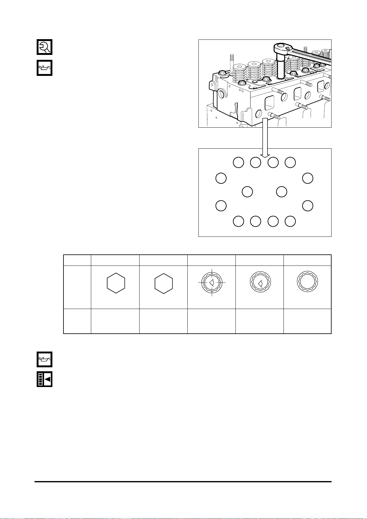
•
Coat the head bolts with engine oil,
then tighten them in proper sequence
to the specified torque.
<Cylinder Head Bolts>
•
Coat the push rod with engine oil and
insert it into the push rod hole.
•
Adjust the valve clearance as following guide.
- 89 -
REASSEMBLY
EAMD102I
Type 1 Type 2 Type 3(12.9T) Type 4(12.9T) Type 5(10.9T)
M14x1.5x153 M14x1.5x150 M14x1.5x153 M14x1.5x150 M14x1.5x150
Tighten
1st : 6 kg.m 1st : 6 kg.m 1st : 7 kg.m 1st : 6 kg.m
torque
24.5 kg.m 2nd : 180
˚ 2nd : 90˚ + 90˚ 2nd :90˚ + 90˚ 2nd : 90˚ + 90˚
Finished : 150˚ Finished : 30˚ Finished : 90˚
TY
12.9T
89
12
32
13
14
11
14
56710
EAMD103I
TY
10.9T
TY
DL08

<Guide for valve clearance adjustment>
•
After letting the #1 cylinder’s piston come at the compression top dead center by turning the
crankshaft, adjust the valve clearances.
•
Loosen the lock nuts of rocker arm adjusting screws and push the feeler gauge of specified
value between a rocker arm and a v alve stem and adjust the clearance with adjusting screw
respectively and then tighten with the lock nut.
•
As for the valve clearance, adjust it when in cold, as follow.
- By cranking the engine, let #6 cylinder’s valves overlap.
- In time, adjust the valve clearance corresponding to ““ of lower figure.
- Rotating the crankshaft by one revolution, #6 cylinder become the compression state of top
dead center.
- Adjust the valve clearance corresponding to ““ of lower figure.
- After reinsuring the valve clearances, retighten if necessary.
•
No.1 Cylinder is located at the side where flywheel was installed.
•
Adjust valve clearance with a feeler
gauge and tighten the fixing nuts to
specified torque.
- 90 -
REASSEMBLY
Model
DE12T
DE12TI
DE12TIA
DE12TIS
0.3 mm 0.3 mm
Intake Valve Exhaust Valve
123456
EA8O6001
Cooling Fan Cylinder No. Exhaust Valve Intake Valve Flywheel
Torque 4.4 kg.m
Valve clearance adjust
EA8M3007

3.3.24. Injection nozzle
•
Install the dust seal with its round portion facing downward.
•
Mount a seal ring on the seal ring
seating surface of the nozzle tube and
assemble nozzle holder assembly
with the stud bolt with the nozzle pipe
installing direction facing outward.
•
Be sure to follow the specified torque.
3.3.25. Cooling water pipe and thermostat
•
Install the water pipe onto the cylinder head.
•
Insert the thermostat in the housing.
•
With socket head bolt, install the
thermostat housing onto the water
pipe.
3.3.26. Oil cooler
•
Install the oil cooler onto the oil cooler cover.
•
Carefully apply the gasket to prevent
oil leakage.
•
Do not damage the gasket and install
the cover onto the cylinder block.
•
Connect a connection pipe between
the water pump and oil cooler.
- 91 -
REASSEMBLY
EAMD105I
Engine model Seal ring
DE12T/TI/TIA 1 mm
DE12TIS 3 mm
Torque 1.0 kg.m
EQM3084I
EAMD106I

3.3.27. Oil filter
•
Install the oil filter onto the cylinder
block, and tighten the fixing bolts.
•
With the hollow screw, assemble the
oil pipe connected between the oil
cooler and cylinder block.
•
Install a connection pipe between
the oil cooler and oil filter.
•
Assemble the cartridge using a filter
wrench.
3.3.28. Injection pump
•
Install the injection pump bracket in
the cylinder block.
•
After measuring the amount of run-out
with an alignment setting jig, disassemble the bracket, adjust the shims,
then reassemble it.
•
Mount the top/bottom adjusting shims
in the bracket and then mount the fuel
injection pump.
•
Tighten the fixing bolts in a diagonal
sequence to specified torque.
- 92 -
REASSEMBLY
Run out 0.2 mm or less
Torque 4.4 kg.m
EAMD107I

•
Turn the flywheel until No. 1 piston is
placed in the “OT” position of notch
marks on the flywheel, and then turn
again the flywheel clockwise until
showing the notch mark of the right
figure corresponding to the injection
timing is aligned with the pointer ( )
on the flywheel housing
•
Turn the timer until the notch mark of
the indicator plate attached to the fuel
injection pump is aligned with the
notch mark of the timer.
•
Tighten the Coupling fixing bolts and
nuts to specified torque.
•
Tighten the drive shaft connecting
flange fixing bolts to specified torque
•
Install the oil delivery pipe and return
pipe.
- 93 -
REASSEMBLY
Timing
check hole
Injection timing
notch mark
Flywheel
ring gear
EE6OM030
Torque 6.0 kg.m
Torque 7.5 ~ 8.5 kg.m
EE6OM013
EAMD021I

3.3.29.Vibration damper and pulley
•
Install the vibration damper on the
crankshaft pulley.
•
Install the crankshaft pulley assembly
on the crankshaft, then tighten the
bolts and thrust washers.
3.3.30.Water pump
•
Mount a new O-ring.
•
Install the water pump drive pinion
over the air compressor spline.
•
Connect water pipes and by-pass
pipe to the water pump.
•
Connect a water pipe to the expansion tank.
3.3.31. Exhaust manifold
•
Install the exhaust manifold gasket
over the stud bolts by aligning the
gasket with the exhaust port on the
cylinder head so that the face and
back of the gasket can be positioned
correctly.
•
Semi-assemble the exhaust manifold and install the heat resisting
plate.
3.3.32.Turbocharger
•
Fit a new gasket over the stud bolts
of the exhaust manifold before tightening those turbocharger fixing
bolts.
•
Install the oil supply pipe and return
pipe.
- 94 -
REASSEMBLY
Torque 13.4 kg.m
EQM3012S
EAMD112I

- 95 -
REASSEMBLY
3.3.33. Air pipe
•
Semi-assemble the bracket to the
intake pipe, connect a rubber hose
between the turbocharger and intake
pipe using the clamps, then assemble the bracket completely.
3.3.34. Starter
•
Assemble the starter in position on
the flywheel housing.
3.3.35. Intake manifold
•
Fit a gasket on the intake manifold
before assembling the intake manifold.
•
Mount the air heater gasket on the
intake manifold, then assemble the
air heater with the intake manifold.
•
Connect the air hoses to the boost
compensator mounted on the fuel
injection pump.
EE6OM031
EQM3100I
EAMD121I

3.3.36. Injection pipe
•
Semi-assemble a nut at both ends of
the fuel high pressure pipe and tighten
them up one by one to specified
torque.
•
Tighten hollow screws to assemble
the fuel return pipe.
•
Assemble the fuel return hose on the
fuel injection pump.
3.3.37. Fuel filter
•
Assemble the fuel filter with the air
pipe bracket.
•
Assemble the fuel feed hose according to the direction of an arrow
impressed on the fuel filter head so
that fuel can be fed in the sequence of
FUEL FEED PUMP FUEL FIL TER
FUEL INJECTION PUMP.
3.3.38. Cylinder head cover
•
Assemble the cover packing with the
cover, install the cover on the head,
then tighten the fixing bolts in
sequence to specified torque.
•
Assemble the breather hose with PCV
valve.
- 96 -
REASSEMBLY
EAMD120I
Torque 1.2 kg.m
Torque 3.0 kg.m
EQM3009I
EE6OM009
EAMD126I
 Loading...