


Engine specifications &
Injection pump datas
DIESEL ENGINE for INDUSTRIAL
D1146T
D1146TI
DE08TS
DE08TIS
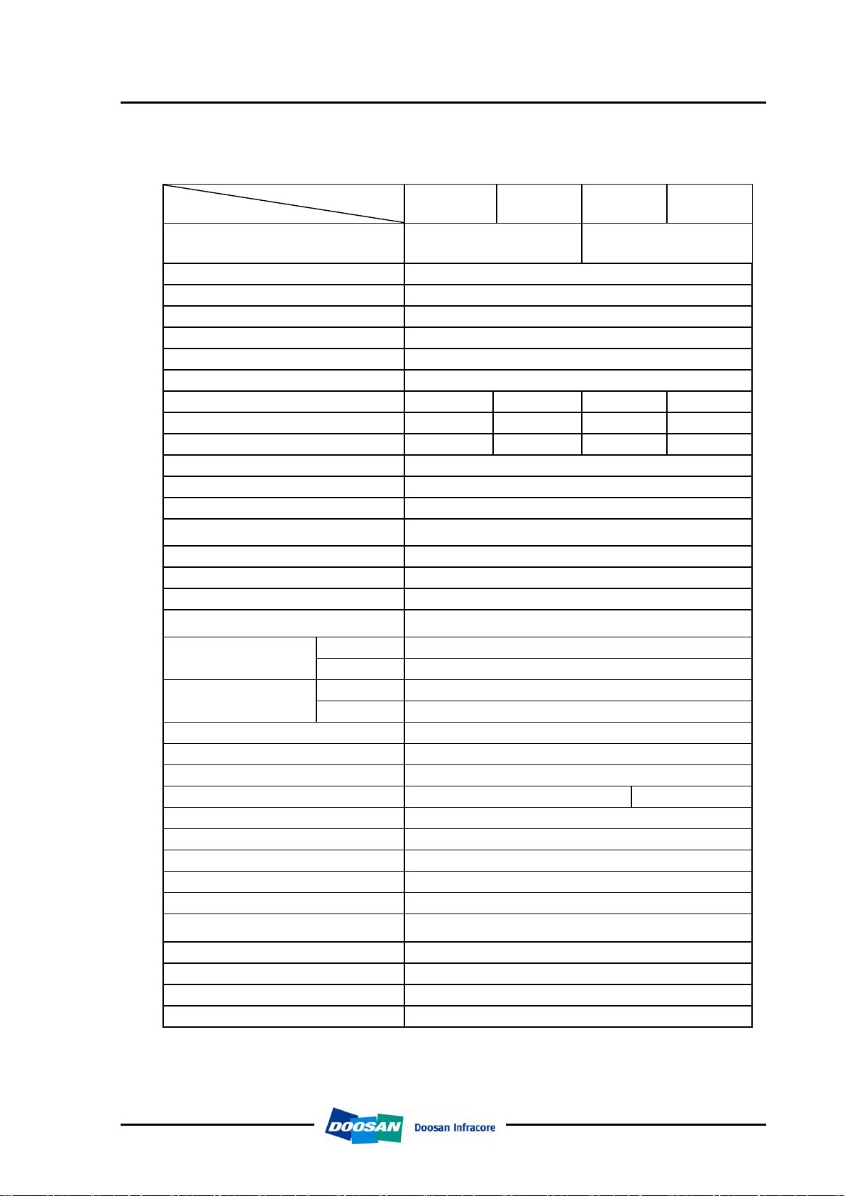
1.1. Engine Specifications
1.1.1. Specification
Engine Model
Items
Engine type
Combustion chamber type Direct injection type
Cylinder liner type Replaceable dry liner
Timing gear system Gear driven type
No. of piston ring Compression ring 2, oil ring 1
No. of cylinder-bore x stroke (mm)
Total piston displacement (cc) 8,071
Compression ratio 16.7 : 1 19.5 : 1 16.7 : 1 19.5 : 1
Engine dimension(length x width x height) (mm)
Engine weight (kg) 720 800 560 800
Rotating direction (viewed from flywheel) Counter clockwise
Fuel injection order 1 – 5 – 3 – 6 – 2 – 4
Injection pump type Bosch in-line type
Governor type
Injection nozzle type Multi-hole type
Fuel injection pressure (kg/cm2) Refer to injection pump rack data
Compression pressure (kg/cm2) 28 (at 200 rpm)
Intake and exhaust valve clearance
(at cold) (mm)
Intake valve
Exhaust valve
Lubrication method Full forced pressure feed type
Using engine oil Above ACEA-E2 (API CH-4) , SAE15W40
Oil pump type Gear type driven by crankshaft
Oil filter type Paper element type Cartridge type
Lubricating oil capacity (max./min.) (lit) 21 / 17 or 31.5 / 20
Oil cooler type Water cooled
Water pump Centrifugal type driven by belt
Cooling Method Fresh water forced circulation
Cooling water capacity (engine only) (lit) 11
Thermostat type
Alternator voltage – capacity (V – A) 24 – 50 (Option)
Starting Motor voltage – output (V - kW) 24 – 6.0
Air heater capacity (V – A) Installed parts of vehicle maker
Battery capacity (V - AH) 24 - 150
Open at
Close at
Open at
Close at
D1146T/D1146TI/DE08TS/DE08TIS
Engine specification & injection pump data for excavator
D1146T DE08TS D1146TI DE08TIS
4 cycle in-line,
Water-cooled type,
Turbo charged
6 – 111 × 139
1,222 x 786 x 1159 1,166 x 727 x 1159 1,123 x 815 x 1,166 1,269.5 x 891 x 1,182
Mechanical governor type
(RSV)
0.3
16° (B.T.D.C)
36° (A.B.D.C)
46° (B.B.D.C)
14° (A.T.D.C)
Wax pallet type
(71 ∼ 85 °C or 71 ∼ 90 °C)
4 cycle in-line,
Water-cooled type
Turbo charged & intercooled
1
Maintenance of major components
Printed in Jan. 2007 PS-MMA0415-E1A
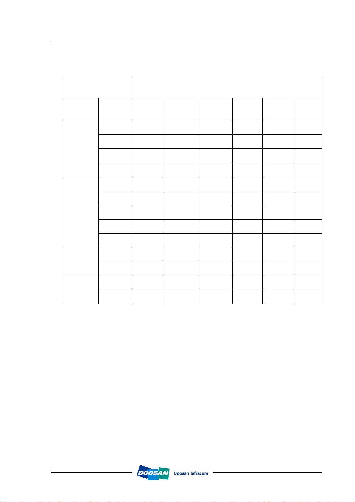
1.1.2. Engine power
Engine model Performance
D1146T/D1146TI/DE08TS/DE08TIS
Engine specification & injection pump data for excavator
Production tolerance : ±5%
Model Suffix
EADEA
EADLA
D1146T
EADLB
EADLC
EAPEA
EAPEB
D1146TI
DE08TS
EAPEC
EAPED
EAPLA
ECDFA
ECDFB
Injection
timing
(BTDC°)
12±1
14±1
12±1
12±1
12±1
15±1
12±1
12±1
12±1
9±1
9±1
Power
(PS/rpm)
170 / 2,000
172 / 2,200
172 / 2,200
172 / 2,200
200 / 1,900
205 / 1,900
185 / 1,900
200 / 1,900
200 / 1,900
140 / 2,200
160 / 2,200
Torque
(kg.m/rpm)
66 / 1,400
69 / 1,300
71 / 1,300
71 / 1,300
80 / 1,400
88 / 1,300
75 / 1,400
88 / 1,300
80 / 1,400
55 / 1,400
63 / 1,400
Low idle
(rpm)
High idle
(rpm)
1,000 2,200
975 2,420
975 2,420
975 2,420
1,000 2,090
1,050 2,090
1,000 2,200
1,050 2,090
1,000 2,090
800 2,400
800 2,400
Remark
DE08TIS
ECPEA
ECPLA
6±1
7±1
205 / 1,900
212 / 2,100
88 / 1,300
90 / 1,300
1,000 2,090
1,000 2,350
* Note : All data are based on operation without cooling fan at ISO 1585(SAE J1349)
2
Maintenance of major components
Printed in Jan. 2007 PS-MMA0415-E1A
Engine specification & injection pump data for excavator
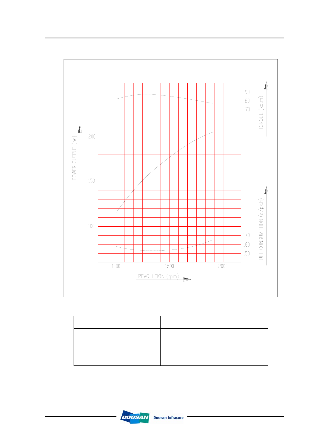
1.1.3. Performance curve (DE08TIS)
D1146T/D1146TI/DE08TS/DE08TIS
Performance ISO 1585(SAE J1349)
Output (max.) 151 kW (205 PS) / 1,900 rpm
Torque (max.) 864 N.m (88 kg.m) / 1,300 rpm
Fuel consumption (rated) 224 g/kW.h (165 g / PS.h)
3
Maintenance of major components
Printed in Jan. 2007 PS-MMA0415-E1A
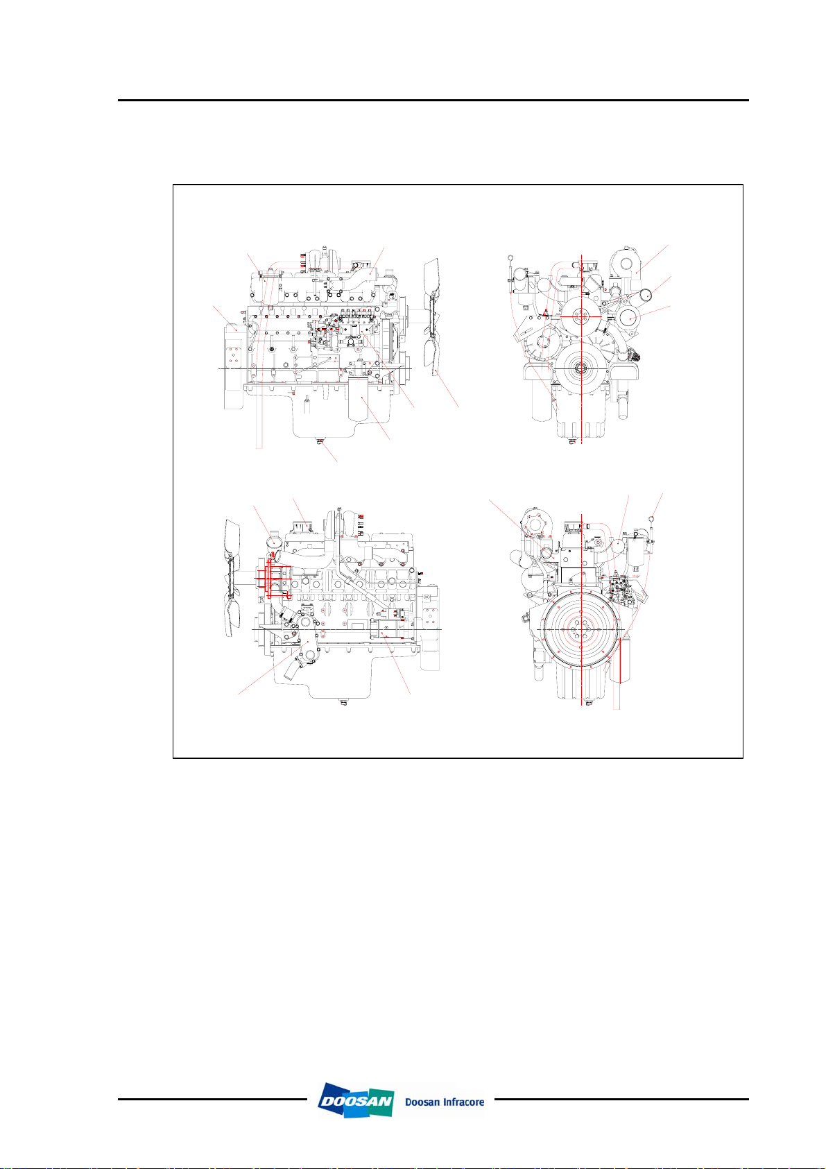
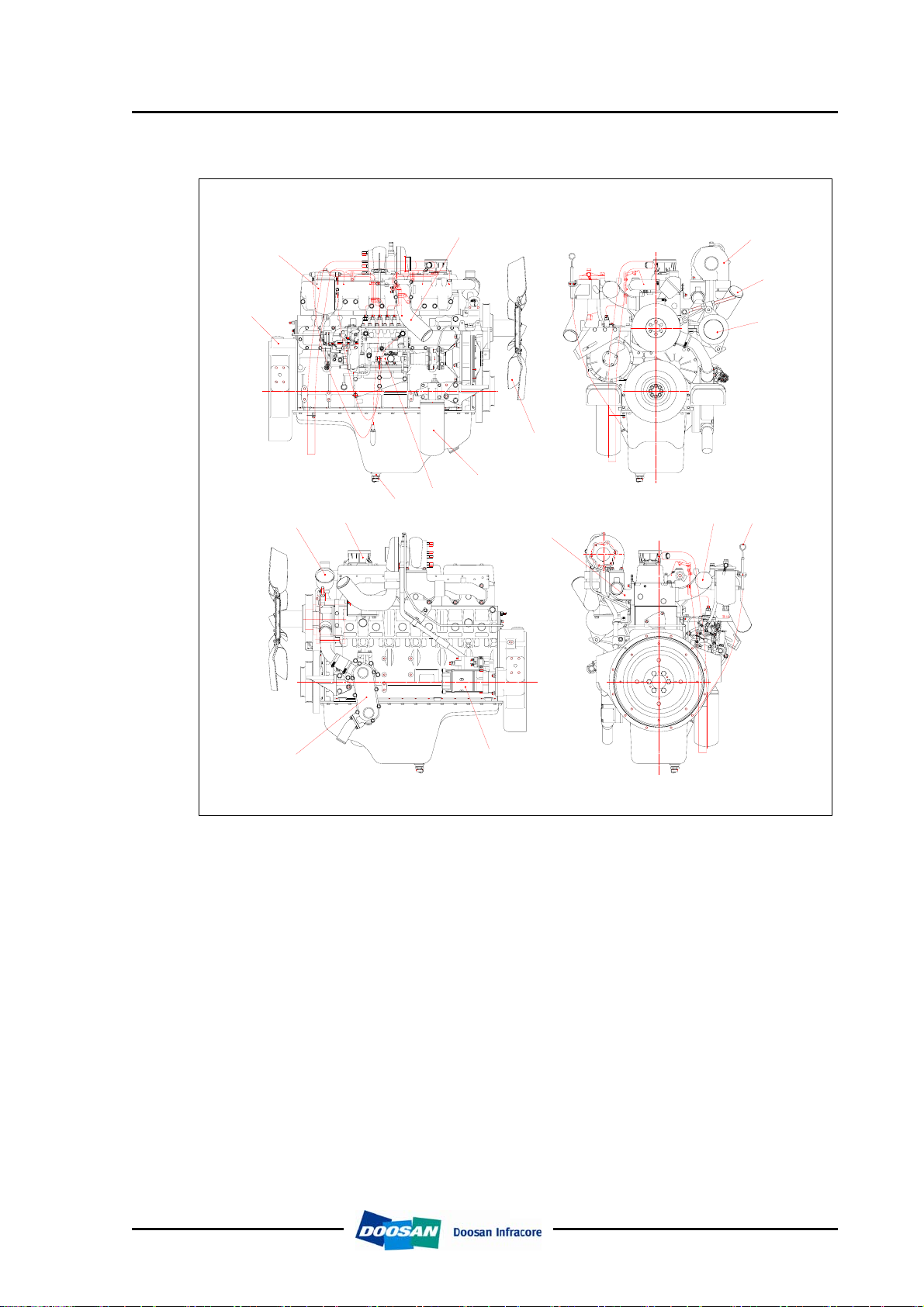
1.1.4. Engine Assembly
D1146T/D1146TI/DE08TS/DE08TIS
Engine specification & injection pump data for excavator
(1) D1146TI
1
2
11
12
3
6
5
4
7
16
15
8
9
10
17
13
14
1 Flywheel housing 10 Alternator
2 Fuel filter 11 Thermostat
3 Air pipe 12 Breather
4 Oil drain plug 13 Oil cooler
5 Oil filter 14 Starter
6 Fuel injection pump 15 Exhaust manifold
7 Cooling fan 16 Intake manifold
8 Turbo charger 17 Oil level gauge
9 Air pipe
4
Maintenance of major components
Printed in Jan. 2007 PS-MMA0415-E1A
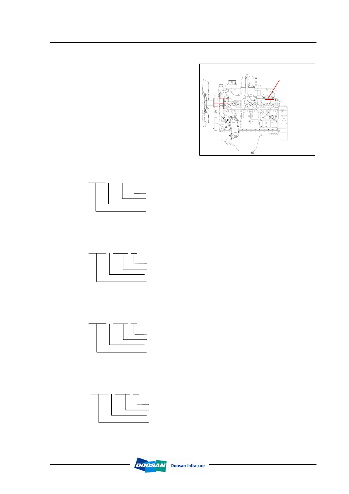
(2) DE08TIS
D1146T/D1146TI/DE08TS/DE08TIS
Engine specification & injection pump data for excavator
3
2
1
7
6
5
11
12
4
15
16 17
8
9
10
13
14
1 Flywheel housing 10 Alternator
2 Fuel filter 11 Thermostat
3 Air pipe 12 Breather
4 Oil drain plug 13 Oil cooler
5 Oil filter 14 Starter
6 Fuel injection pump 15 Exhaust manifold
7 Cooling fan 16 Intake manifold
8 Turbo charger 17 Oil level gauge
9 Air pipe
5
Maintenance of major components
Printed in Jan. 2007 PS-MMA0415-E1A
Engine specification & injection pump data for excavator
1.1.5. Engine model and serial number
z The engine model and serial
number is located on the engine
as illustrated.
z These numbers are required
when requesting warranty and
ordering parts. They are also
referred to as engine model and
serial number because of their
location.
z Engine serial No. (example 1 : D1146T)
D1146T/D1146TI/DE08TS/DE08TIS
Engine number
(located the cylinder block)
D1146T 6 00001 EA
Engine suffix(EADEA)
Serial no.
Production year(2006)
Engine model
z Engine serial No. (example 1 : D1146TI)
D1146TI 6 00001 EA
Engine suffix(EAPEA)
Serial no.
Production year(2006)
Engine model
z Engine serial No. (example 1 : DE08TS)
DE08TS 7 00001 EA
Engine suffix(EAPEA)
Serial no.
Production year(2007)
Engine model
z Engine serial No. (example 1 : DE08TIS)
DE08TIS 7 00001 EA
Engine suffix(EAPEA)
Serial no.
Production year(2007)
Engine model
6
Maintenance of major components
Printed in Jan. 2007 PS-MMA0415-E1A

Engine specification & injection pump data for excavator
1.1.6. Parts no of injection system
1) Injection pump assembly
Engine model Part no. Suffix
D1146T/D1146TI/DE08TS/DE08TIS
D1146T
D1146TI
DE08TS 65.11101-7388 ECDFA, ECDFB
DE08TIS 65.11101-7356A ECPEA, ECPLA
2) Injection nozzle assembly
Engine model Part no. Suffix
D1146
D1146T
D1146TI 65.10101-7080A EAPEA, EAPEB, EAPEC, EAPED, EAPLA
DE08TS
DE08TIS
3) Injection pipe assembly
65.11101-7387
65.10101-7050A
65.10101-7088 ECDFA, ECDFB, ECPEA, ECPLA
EADEA, EAPEA, EAPEB, EAPEC, EAPED,
EAPLA
EACEA, EACEB, EACEC, EACED, EACEE,
EACEF, EACEG, EACFA, EACFB, EADEA,
EADLA, EADLB, EADLC
Engine model Part no. Suffix
65.10301-6036A EACEA, EACEB, EACEC
D1146
65.10301-6040A
D1146T
D1146TI
DE08TS
DE08TIS
65.10301-6048C
65.10301-6049B
65.10301-6052B
EACED, EACEE, EACEF, EACEG, EACFA,
EACFB
EADEA, EADLA, EADLB, EADLC, EAPEA,
EAPEB, EAPEC, EAPED, EAPLA, ECDFA,
ECDFB
ECPEA, ECPLA
7
Maintenance of major components
Printed in Jan. 2007 PS-MMA0415-E1A

D1146T/D1146TI/DE08TS/DE08TIS
Engine specification & injection pump data for excavator
1.1.7. Injection pump calibration data
(1) D1146T engine : EADEA
1) Injection pump assembly : 65.11101-7387 (101609-904A DOOWON)
- Injection pump : KP-PE6AD95B410RS2 (101062-8240)
- Governor : KP-EP/RSV200/1300AQ39C311 (105411-2150)
- Plunger and barrel : 131150-2400, 131100-8500
- Delivery valve : 131110-5120
- Feed pump : KP-FP/KE-ADS (105210-5610)
- Prestroke : 4.3±0.05mm
2) Nozzle holder assembly : 65.10101-7050A (9135-153 Delphi)
3) Nozzle : 65.10102-6026A (9135-143 Delphi)
4) Injection pipe : 65.10301-6048C
5) Injection order : 1 – 5 – 3 – 6 – 2 – 4
(A) Test condition
for injection pump
(B) Engine standard parts
Rack diagram and setting valve at each point : Specification of standard pump(65.11101-7387)
Nozzle & holder ass’y 105780-8140 Opening pressure :175kg/cm
Injection pipe(IDxODxL) - φ2.0 x φ6.0 – 600 mm
Test oil ISO4113 Temperature : 40 ±5°C
Nozzle & holder ass’y
65.10102-6026A Nozzle (5 x φ0.29)
65.10101-7050A 214+8 kg/cm
Injection pipe(IDxODxL) 65.10301-6048C φ2.0 x φ6.0 x 650mm
Injection Q`ty on RIG
3
(mm
for inj. pump
/ 1,000st) Check
(B) Engine
standard parts
Point
Rack
position
(mm)
Pump
speed
(rpm)
(A) Test condition
A 10.1 1000 100.0 ±2.0 Above 500
B ≈ 7.6 525 20.0 ±1.5 0
C R1(10.1) 550 (100) Above 500
D R-1.0 550 (84) 0
Above
E
14.0
100 (150) 0
2
Press.
(mmHg)
2
Fuel injection pump
Plunger φ9.5 Left hand 20 lead retraction pressure 70mm3/st(φ6x2.5mm)
Max. pump speed
(limit plunger bouncing)
Holder delivery valve
with damping valve
Governor
Governor weight 740 g Lever ratio (min. speed / max. speed) 1 : 1.2 / 1 : 1.2
Governor spring k=7.2 kgf/mm Idling sub spring k=2.5 kgf/mm
Idling spring k=1.9 kgf/mm Start spring k=0.01 kgf/mm
Boost compensator spring k=0.7 kgf/mm - -
Feed pump
Max. operating pressure 3.4 kgf/cm2 Piston spring k=0.735 kgf/mm
8
1,970 rpm opening pressure 23.1 kgf/cm
Orifice diameter φ0.7
Delivery valve
Spring k=1.63 kgf/mm
Maintenance of major components
Printed in Jan. 2007 PS-MMA0415-E1A
2

D1146T/D1146TI/DE08TS/DE08TIS
Engine specification & injection pump data for excavator
f) Rack curve of standard injection pump (65.11101-7387)
Rack curve
Boost pressure
9
Maintenance of major components
Printed in Jan. 2007 PS-MMA0415-E1A

D1146T/D1146TI/DE08TS/DE08TIS
Engine specification & injection pump data for excavator
(2) D1146TI engine : EAPEA, EAPEB, EAPEC, EAPED, EAPLA
1) Injection pump assembly : 65.11101-7387 (101609-904A DOOWON)
- Injection pump : KP-PE6AD95B410RS2 (101062-8240)
- Governor : KP-EP/RSV200/1300AQ39C311 (105411-2150)
- Plunger and barrel : 131150-2400,131100-8500
- Delivery valve : 131110-5120
- Feed pump : KP-FP/KE-ADS (105210-5610)
- Prestroke : 4.3±0.05mm
2) Nozzle holder assembly : 65.10101-7080A (9135-277 Delphi)
3) Nozzle : 65.10102-6040A (9135-276 Delphi)
4) Injection pipe : 65.10301-6048C
5) Injection order : 1 – 5 – 3 – 6 – 2 – 4
(A) Test condition
for injection pump
(B) Engine standard parts
Rack diagram and setting valve at each point : Specification of standard pump(65.11101-7387)
Nozzle & holder ass’y 105780-8140 Opening pressure :175kg/cm
Injection pipe(IDxODxL) - φ2.0 x φ6.0 – 600 mm
Test oil ISO4113 Temperature : 40 ±5°C
Nozzle & holder ass’y
65.10102-6040A Nozzle (5 x φ0.30)
65.10101-7080A 214+8 kg/cm
Injection pipe(IDxODxL) 65.10301-6048C φ2.0 x φ6.0 x 650mm
Injection Q`ty on RIG
3
(mm
for inj. pump
/ 1,000st) Check
(B) Engine
standard parts
Point
Rack
position
(mm)
Pump
speed
(rpm)
(A) Test condition
A 11.8 950 128.0 ±2.0 Above 500
B ≈ 7.6 525 20.0 ±1.5 0
C R1(12.4) 550 (120) Above 500
D R-1.0 550 (104) 0
Above
E
14.0
100 (150) 0
2
Press.
(mmHg)
2
Fuel injection pump
Plunger φ9.5 Left hand 20 lead retraction pressure 70mm3/st(φ6x2.5mm)
Max. pump speed
(limit plunger bouncing)
Holder delivery valve
with damping valve
Governor
Governor weight 740 g Lever ratio (min. speed / max. speed) 1 : 1.2 / 1 : 1.2
Governor spring k=7.2 kgf/mm Idling sub spring k=2.5 kgf/mm
Idling spring k=1.9 kgf/mm Start spring k=0.01 kgf/mm
Boost compensator spring k=0.7 kgf/mm - -
Feed pump
Max. operating pressure 3.4 kgf/cm2 Piston spring k=0.735 kgf/mm
1,970 rpm opening pressure 23.1 kgf/cm
Orifice diameter φ0.7
Delivery valve
Spring k=1.63 kgf/mm
10
Maintenance of major components
Printed in Jan. 2007 PS-MMA0415-E1A
2

Engine specification & injection pump data for excavator
6) Rack diagram and setting valve at each point
a) D1146TI : EAPEA
Check Point
A
B
C
D
E
Rack position
(mm)
12.4 950 128.0 ±2.0
≈ 7.6 525 20.0 ±1.5
R1(12.4) 550 (120)
R-1.0 550 (104)
Above 14.0
b) D1146TI : EAPEB
Check Point
A
B
C
D
E
Rack position
(mm)
12.4 950 128.0 ±2.0
≈ 7.6 525 20.0 ±1.5
R1(12.4) 550 (120)
R-1.0 550 (104)
Above 14.0
c) D1146TI : EAPEC
Check
Point
A
B
C
D
E
Rack position
(mm)
12.4 950 124.0 ±2.0
≈ 7.6 525 20.0 ±1.5
R1(12.4) 550 (120)
R-1.0 550 (104)
Above 14.0
d) D1146TI : EAPED
Check
Point
A
B
C
D
E
Rack position
(mm)
12.4 950 124.0 ±2.0
≈ 7.6 525 20.0 ±1.5
R1(12.4)
R-1.0 550 (104)
Above 14.0
e) D1146TI : EAPLA
Check
Point
A
B
C
D
E
Rack position
(mm)
12.4 950 126.0 ±2.0
≈ 7.6 525 20.0 ±1.5
R1(12.4) 550 (120)
R-1.0 550 (104)
Above 14.0
Pump speed
(rpm)
Pump speed
(rpm)
Pump speed
(rpm)
Pump speed
(rpm)
Pump speed
(rpm)
D1146T/D1146TI/DE08TS/DE08TIS
Injection Q`ty on RIG
(mm3 / 1,000st)
100 (150)
Injection Q`ty on RIG
3
/ 1,000st)
(mm
100 (150)
Injection Q`ty on RIG
3
/ 1,000st)
(mm
100 (150)
Injection Q`ty on RIG
3
(mm
/ 1,000st)
550 (120)
100 (150)
Injection Q`ty on RIG
3
(mm
/ 1,000st)
100 (150)
Pressure
(mmHg)
Above 500
Above 500
Pressure
(mmHg)
Above 500
Above 500
Pressure
(mmHg)
Above 500
Above 500
Pressure
(mmHg)
Above 500
Above 500
Pressure
(mmHg)
Above 500
Above 500
0
0
0
0
0
0
0
0
0
0
0
0
0
0
0
11
Maintenance of major components
Printed in Jan. 2007 PS-MMA0415-E1A

D1146T/D1146TI/DE08TS/DE08TIS
Engine specification & injection pump data for excavator
f) Rack curve of standard injection pump (65.11101-7387)
Rack curve
Boost pressure
12
Maintenance of major components
Printed in Jan. 2007 PS-MMA0415-E1A

D1146T/D1146TI/DE08TS/DE08TIS
Engine specification & injection pump data for excavator
(3) DE08TS engine : ECDFA, ECDFB
1) Injection pump assembly : 65.11101-7388 (101609-904F DOOWON)
- Injection pump : KP-PES6AD95B410RS2 (101062-8240)
- Governor : KP-EP/RSV200-1300AQ39C311 (105411-215A)
- Plunger and barrel : 131150-2400,131100-8500
- Delivery valve : 131110-5120
- Feed pump : KP-FP/KE-ADS (105210-5610)
- Prestroke : 4.3±0.05mm
2) Nozzle holder assembly : 65.10101-7088 (Y 430 K02 049 Bosch)
3) Nozzle : 65.10102-6058 (0 433 171 736 Bosch)
4) Injection pipe : 65.10301-6048C
5) Injection order : 1 – 5 – 3 – 6 – 2 – 4
(A) Test condition
for injection pump
(B) Engine standard parts
Rack diagram and setting valve at each point : Specification of standard pump(65.11101-7388)
Nozzle & holder ass’y 105780-8140 Opening pressure :175kg/cm
Injection pipe(IDxODxL) - φ2.0 x φ6.0 – 600 mm
Test oil ISO4113 Temperature : 40 ±5°C
Nozzle & holder ass’y
65.10102-6058 Nozzle (8 x φ0.218)
65.10101-7088 180/280 kg/cm
Injection pipe(IDxODxL) 65.10301-6048C φ2.0 x φ6.0 x 650mm
Injection Q`ty on RIG
3
(mm
for inj. pump
/ 1,000st) Check
(B) Engine
standard parts
Point
Rack
position
(mm)
Pump
speed
(rpm)
(A) Test condition
A 11.4 1100 104.0 ±2.0 Basic
B ≈ 8.2 400 20.0 ±1.5 -
C R1(11.4) 550 (100) -
D (R1-0.7) 550 (87) -
Above
E
14.0
100 (166)
Boost pressure : zero boost
2
Press.
(mmHg)
2
Fuel injection pump
Plunger φ9.5 Left hand 20 lead retraction pressure 70mm3/st(φ6x2.5mm)
Max. pump speed
(limit plunger bouncing)
Holder delivery valve
with damping valve
Governor
Governor weight 740 g Lever ratio (min. speed / max. speed) 1 : 1.2 / 1 : 1.2
Governor spring k=7.2 kgf/mm Idling sub spring k=2.5 kgf/mm
Idling spring k=1.9 kgf/mm Start spring k=0.01 kgf/mm
Boost compensator spring k=0.51 kgf/mm - -
Feed pump
Max. operating pressure 3.4 kgf/cm2 Piston spring k=0.735 kgf/mm
1,970 rpm opening pressure 23.1 kgf/cm
Orifice diameter φ0.7
Delivery valve
Spring k=1.63 kgf/mm
13
Maintenance of major components
Printed in Jan. 2007 PS-MMA0415-E1A
2

Engine specification & injection pump data for excavator
6) Rack diagram and setting valve at each point
a) DE08TS : ECDFA
Check Point
A
B
C
D
E
Rack position
(mm)
11.4 1100 91.0 ±2.0
≈ 8.2 400 20.0 ±1.5
R1(11.4) 550 (90)
(R1-0.7) 550 (77)
Above
14.0
b) DE08TS : ECDFB
Check Point
A
B
C
D
E
Rack position
(mm)
11.4 1100 104.0 ±2.0
≈ 8.2 400 20.0 ±1.5
R1(11.4) 550 (100)
(R1-0.7) 550 (87)
Above
14.0
Pump speed
Pump speed
D1146T/D1146TI/DE08TS/DE08TIS
Injection Q`ty on RIG
(rpm)
(mm3 / 1,000st)
100 (166)
Injection Q`ty on RIG
3
(rpm)
(mm
/ 1,000st)
100 (166)
Pressure
(mmHg)
Above 250
Above 250
Pressure
(mmHg)
Above 250
Above 250
0
0
0
0
0
0
14
Maintenance of major components
Printed in Jan. 2007 PS-MMA0415-E1A

D1146T/D1146TI/DE08TS/DE08TIS
Engine specification & injection pump data for excavator
(4) DE08TIS engine : ECPEA, ECPLA
1) Injection pump assembly : 65.11101-7356A (106675-466B DOOWON)
- Injection pump : KP-PE6P120/721RS3S (106067-180B)
- Governor : KP-EP/RFD200-1400PF57DZR (105407-620B)
- Plunger and barrel : 134151-2300,134100-3000
- Delivery valve : 134110-1420
- Feed pump : KP-FP/K-PS (105207-1540)
- Prestroke : 3.9±0.05mm
- Coupling : 105663-074B
2) Nozzle holder assembly : 65.10101-7088 (Y 430 K02 049 Bosch)
3) Nozzle : 65.10102-6058 (0 433 171 736 Bosch)
4) Injection pipe : 65.10301-6049B
65.10301-6052B
5) Injection order : 1 – 5 – 3 – 6 – 2 – 4
(A) Test condition
for injection pump
(B) Engine standard parts
Rack diagram and setting valve at each point : Specification of standard pump(65.11101-7356A)
Nozzle & holder ass’y 105780-8140 Opening pressure :175kg/cm
Injection pipe(IDxODxL) - φ3.0 x φ8.0 – 600 mm
Test oil ISO4113 Temperature : 40 ±5°C
Nozzle & holder ass’y
Injection pipe(IDxODxL)
Rack
Check
position
Point
(mm)
65.10102-6058 Nozzle (8 x φ0.218)
65.10101-7088 180/280 kg/cm
65.10301-6049B
65.10301-6052B
Pump
speed
(rpm)
(A) Test condition
for inj. pump
Injection Q`ty on RIG
φ2.2 x φ6.35 x 650mm
(mm3 / 1,000st)
(B) Engine
standard parts
A R1(11.5) 950 151 ±2.0 Basic
B ≈ 6.5 550 13.0 ±1.5 -
C R1 650 (155) -
D (R1-1.0) 650 (122) -
E
-
100 180 ±10
2
Press.
(mmHg)
2
Fuel injection pump
3
/st(φ8x2.0mm)
Plunger φ12 Right hand 30 lead retraction pressure
Max. pump speed
(limit plunger bouncing)
Holder delivery valve
with damping valve
Governor
Governor weight 740 g Lever ratio (min. speed / max. speed) 1 : 1.2 / 1 : 1.2
Governor spring k=7.2 kgf/mm Idling sub spring k=1.2 kgf/mm
Idling spring k=1.9 kgf/mm Start spring k=0.01 kgf/mm
Boost compensator spring k=0.1 kgf/mm - -
Feed pump
Max. operating pressure 3.0 kgf/cm2 Piston spring k=0.735 kgf/mm
1,600 rpm opening pressure 19.6 kgf/cm
Orifice diameter φ0.7
Delivery valve
Spring k=0.87 kgf/mm
100mm
t = 0.09mm
15
Maintenance of major components
Printed in Jan. 2007 PS-MMA0415-E1A
2

Engine specification & injection pump data for excavator
6) Rack diagram and setting valve at each point
a) DE08TIS : ECPEA
Check Point
A
B
C
D
E
Rack position
(mm)
R1(11.5) 950 151 ±2.0
≈ 6.5 550 13.0 ±1.5
R1 650 (155)
(R1-1.0) 650 (122)
-
b) DE08TIS : ECPLA
Check Point
A
B
C
D
E
Rack position
(mm)
R1(11.5) 950 151 ±2.0
≈ 6.5 550 13.0 ±1.5
R1 650 (155)
(R1-1.0) 650 (122)
-
Pump speed
(rpm)
Pump speed
(rpm)
D1146T/D1146TI/DE08TS/DE08TIS
Injection Q`ty on RIG
(mm3 / 1,000st)
100 180 ±10
Injection Q`ty on RIG
3
/ 1,000st)
(mm
100 180 ±10
Pressure
(mmHg)
Above 300
0
Above 300
0
0
Pressure
(mmHg)
Above 300
0
Above 300
0
0
16
Maintenance of major components
Printed in Jan. 2007 PS-MMA0415-E1A
 Loading...