


Electrical System

SP001038
ELECTRICAL SYSTEMSP001038
Electrical
System
Edition 1
Electrical System |
SP001038 |
|
Page 1 |

MEMO
Electrical System |
SP001038 |
Page 2 |
|

Table of Contents |
|
Electrical System |
|
Safety Precautions ............................................... |
7 |
Applicable Models ................................................ |
7 |
Introduction ........................................................... |
9 |
Electrical Supply System .................................... |
10 |
Engine Starting Circuit ........................................ |
12 |
Start Operation .............................................................. |
12 |
After Start ...................................................................... |
14 |
Engine Preheating System ................................. |
16 |
Engine Stop ........................................................ |
18 |
Charging System ................................................ |
20 |
Monitoring System .............................................. |
21 |
Instrument Panel ........................................................... |
22 |
Monitoring System Schematic ....................................... |
24 |
Operation ............................................................ |
26 |
Instruments.................................................................... |
26 |
Warning and Indicator Lights .............................. |
28 |
Indication of Warning Lights .......................................... |
28 |
Indication of Multifunction Gauge and |
|
Letter Information Area.................................................. |
29 |
Initial Operation .................................................. |
31 |
Mode Selector Switch ......................................... |
31 |
Graphic Information Area Display....................... |
32 |
Overview ....................................................................... |
32 |
Main Menus for the Graphic Display Area..................... |
33 |
Menu Selector Buttons .................................................. |
33 |
Main Menu .......................................................... |
34 |
Language ...................................................................... |
34 |
Set Clock ....................................................................... |
35 |
Filter/Oil Info .................................................................. |
35 |
Adjust Display................................................................ |
36 |
Electrical System |
SP001038 |
|
Page 3 |

Set Password ................................................................ |
37 |
Special Menu ...................................................... |
38 |
Entering/Accessing and Exiting/Escaping Menus ......... |
38 |
Special Menu Selections ............................................... |
39 |
Electronic Hydraulic Control System (e-EPOS).. |
56 |
Control System Schematic ............................................ |
56 |
Power Mode Control ........................................... |
58 |
Operation....................................................................... |
60 |
Power Mode Control - Circuit Diagram ............... |
62 |
Work Mode Control............................................. |
64 |
Operation....................................................................... |
65 |
Work Mode Control - Circuit Diagram................. |
66 |
Engine Control System ....................................... |
67 |
Engine Control Dial............................................. |
68 |
Engine Control Circuit Diagram .......................... |
69 |
Automatic Deceleration Control |
|
(Auto Idle Control) .............................................. |
70 |
Engine Overheat Protection System .................. |
72 |
Power Boost Mode ............................................. |
74 |
Operation....................................................................... |
74 |
Power Boost Control - Circuit Diagram ......................... |
76 |
Automatic Travel Speed Control......................... |
78 |
Automatic Travel Speed Control - Circuit Diagram ....... |
80 |
Self-diagnostic Function ..................................... |
81 |
e-EPOS Controller......................................................... |
81 |
Air Conditioner System ....................................... |
83 |
Outline ........................................................................... |
83 |
Internal and External Filters .......................................... |
84 |
Air-Conditioning System Layout .................................... |
86 |
Air Conditioner/heater Circuit Diagram.......................... |
87 |
Air Conditioner/heater Unit ............................................ |
88 |
Ambient Air Temperature Sensor .................................. |
93 |
Electrical System |
SP001038 |
Page 4 |
|

Sun Sensor.................................................................... |
94 |
Control Panel................................................................. |
94 |
Compressor ................................................................. |
102 |
Receiver Dryer ............................................................ |
102 |
Troubleshooting ................................................ |
103 |
Weight of R134a Gas Used In Machines ......... |
105 |
Refrigerant System Repairs ............................. |
106 |
Refrigerant Safe Handling Procedures........................ |
106 |
Repair and Replacement Procedure ........................... |
107 |
Refrigerant Recovery .................................................. |
109 |
Vacuuming Refrigerant System................................... |
109 |
Leakage Check ........................................................... |
111 |
Refrigerant Charging ................................................... |
111 |
Inspecting System For Leakage .................................. |
113 |
Wiper System ................................................... |
114 |
Wiper Circuit................................................................ |
114 |
Wiper operation ........................................................... |
115 |
Lighting System ................................................ |
118 |
Lighting System Circuit Diagram ................................. |
118 |
Kind of Light ................................................................ |
119 |
Operation..................................................................... |
119 |
Audio Controller ................................................ |
120 |
Audio Controller Circuit Diagram ................................. |
120 |
Electrical System |
SP001038 |
|
Page 5 |

MEMO
Electrical System |
SP001038 |
Page 6 |
|

SAFETY PRECAUTIONS
CAUTION!
Follow all safety recommendations and safe shop practices outlined in the front of this manual or those contained within this section.
Always use tools and equipment that are in good working order.
Use lifting and hoisting equipment capable of safely handling load.
Remember, that ultimately safety is your own personal responsibility.
APPLICABLE MODELS
The contents of this section apply to the following models and serial number ranges.
MODEL |
SERIAL NUMBER RANGE |
|
|
DX140LC |
5001 and Up |
|
|
DX180LC |
5001 and Up |
|
|
|
|
Electrical System |
SP001038 |
|
Page 7 |

Electrical System |
SP001038 |
Page 8 |
|
INTRODUCTION
The electrical system for this equipment is DC 24 volts. The rated voltage for all electric components is 24 volts with the exception of the stereo and the air-conditioning control actuator. The system contains two 12 volt batteries connected in series and a three phase AC generator with a rectifier. The electric wiring used in the system is easily identifiable by the insulator color. The color symbols used in the electrical system are listed in the following chart.
Electric Wire Color
Symbol |
Color |
|
|
W |
White |
|
|
G |
Green |
|
|
Or |
Orange |
|
|
B |
Black |
|
|
L |
Blue |
|
|
Lg |
Light green |
|
|
R |
Red |
|
|
Gr |
Gray |
|
|
P |
Pink |
|
|
Y |
Yellow |
|
|
Br |
Brown |
|
|
V |
Violet |
|
|
NOTE: RW: Red wire with White stripe
R - Base Color, W - Stripe Color
NOTE: 0.85G: Nominal sectional area of wire core less insulator = 0.85 mm2
Electrical System |
SP001038 |
|
Page 9 |

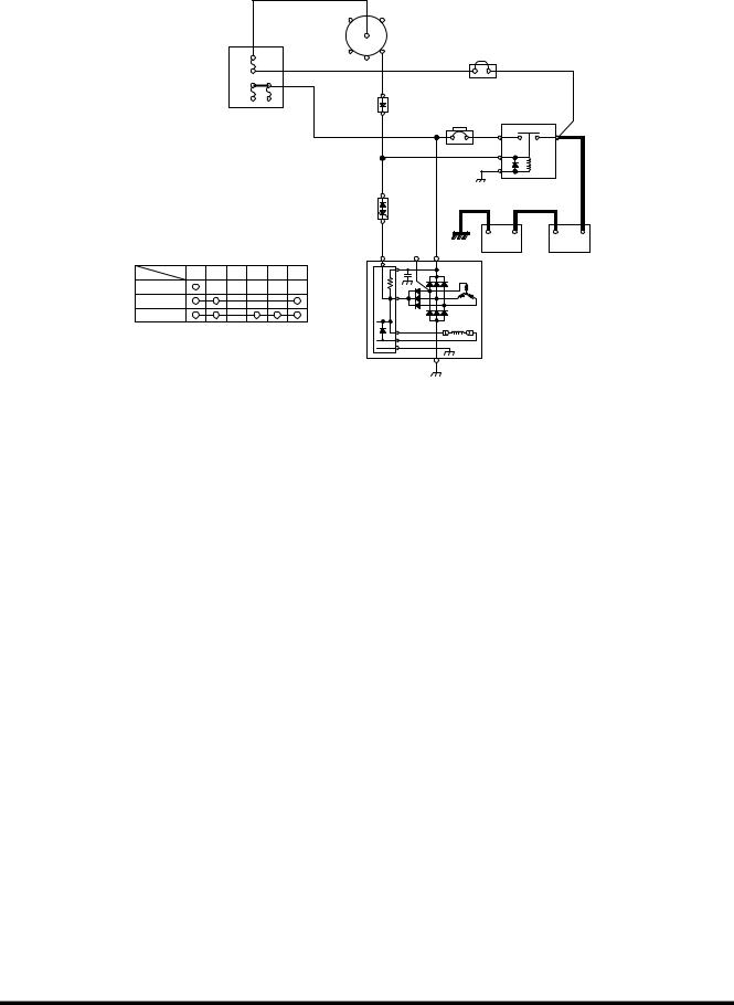
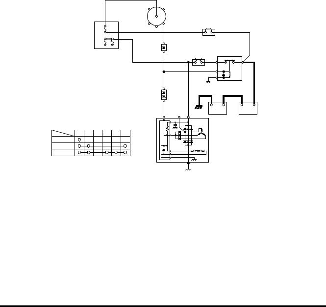
ELECTRICAL SUPPLY SYSTEM
The electric power circuit supplies electric current to each electric component. It consists of a battery, battery relay, starter switch, circuit breaker, fusible link and fuse box.
The negative terminal of the battery is grounded to the vehicle body.
Even when the starter switch (5) is in the "OFF" position, electric currento is supplied toothe following components through battery
(1) fusible link (3) fuse box (6).
1.Terminal "1" of DC-DC converter (for memory backup of stereo)
2.Terminal "B" of starter switch
3.Hour meter
4.Engine controller
5.Fuel feeder pump switch
6.Terminal "6" of wiper motor
7.Terminal "13" of wiper controller
8.Terminal "CN6-11" of instrument panel
9.Terminal "CN9-6" of air conditioner panel
10.Cabin light
When the starter switch (5) is in the "ONo or START" positions,o
the currento flows from the battery (1) fusibleo link (3) fuse box (6) "B" terminalo of starter switch (5) "BR" terminal of starter switch (5) "BR" terminal of battery relay (2) which activates the coil of the battery relay and the electric supply system is energized.
When the battery relay's contacts are connected, all electric devices can be operated.
While the engine is not running, the electric power for all electric devices are supplied by the battery. Once the engine is started the power is supplied from the alternator (7).
Electrical System |
SP001038 |
Page 10 |
|
ACC |
C |
B5
|
|
|
R2 |
BR |
|
|
|
|
|
|
|
|
|
|
|
|
0.5G |
|
|
|
|
|
|
|
|
R1 |
|
|
|
|
|
|
|
|
|
|
|
|
|
|
|
|
|
|
|
6 |
|
|
|
|
3 |
|
|
|
|
|
|
|
|
|
|
|
|
|
|
|
|
|
|
8 |
|
|
|
|
2 |
|
|
|
|
|
|
|
4 |
|
|
|
|
|
|
|
|
|
|
|
|
|
|
|
|
|
|
|
|
|
|
B |
|
A |
|
|
|
|
|
|
|
|
BR |
|
|
|
|
|
|
|
|
|
|
E |
|
|
|
|
|
|
|
8 |
|
|
|
|
|
|
|
|
|
|
|
|
|
- |
+ |
- |
+ |
STARTER SWITCH CONNECTION |
|
R(I) |
P(R) |
B(B+) |
12V 100AH |
|
12V 100AH |
|
||
|
|
|
1 |
|
||||||
|
TML |
|
|
0.5 uF |
|
|
|
|
|
|
PST |
B BR R1 R2 C ACC |
|
B+ |
|
|
|
|
|
|
|
|
|
|
|
|
|
|
|
|||
OFF |
|
|
|
I(L) |
|
|
|
|
|
|
|
|
|
|
|
|
7 |
|
|
|
|
ON |
|
|
|
|
|
|
|
|
|
|
|
|
|
|
REG. |
|
|
|
|
|
|
START |
|
|
|
TRIO DIODE |
|
|
|
|
|
|
|
|
|
|
|
|
|
|
|
|
|
|
|
|
|
F+ |
|
FIELD |
|
|
|
|
|
|
|
|
|
|
|
|
|
|
|
F-
E
 GRD
GRD
FG007233
Figure 1 ELECTRIC POWER CIRCUIT DIAGRAM
Reference |
Description |
|
Number |
||
|
||
|
|
|
1 |
Battery |
|
|
|
|
2 |
Battery Relay |
|
|
|
|
3 |
Fusible Link |
|
|
|
|
4 |
Circuit Breaker |
|
|
|
Reference |
Description |
|
Number |
||
|
||
|
|
|
5 |
Starter Switch |
|
|
|
|
6 |
Fuse Box |
|
|
|
|
7 |
Alternator |
|
|
|
|
8 |
Diode |
|
|
|
Electrical System |
SP001038 |
|
Page 11 |
ENGINE STARTING CIRCUIT
Start Operation
When the starter switch is turned to the "START" position, the "S" and "E" terminals of the starter controller (7) are connected. At this time the contacts in the startero relay (8) areoclosed by the ocurrent flow from the battery (1) fusibleo link (3) fuse box (6)
"B" terminalo of starter switch (5) "C" terminal of startero switch (5) "30" terminal of starter relay (12) -o"87a" terminal "C" terminal of starter relay (8) - "D"o terminal "S" terminal of starter controller (7) - "E" terminal ground.
When the contact point "B" and "PP" of starter relay (8) are connected, the pinion gear of the starter (9) is pushed forward and makes contact with the ring gear of the flywheel and the internal contacts of theo starter are connected. The currentoflows from the battery (1) "A" terminal of the batteryo relay (2) "B" terminal of the battery relay (2, Figure 3) "B" terminal of the starter (9). The starter motor is rotated and the engine is started.
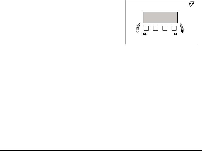
If the instrument panel has the password function activated , input number should match the set number, otherwise the start circuit closes and the engine does not start.
NOTE: If the security system is "LOCKED," a four-digit password will be required to start the engine. If the system is "UNLOCKED," no password will be required and this display screen will not appear.
In the event the securityo system is locked,o current flowsofrom battery (1) fusible link (3) ofuse box
(6) "B" terminal of startero switch (5) "ACC" terminal of startero switch (5) "86" terminal of startero relay (12) "85" terminal of startero relay (12)
"CN1-15" terminal of e-EPOS (13) ground. This current flow causes the coil in starter relay (12) to be activated, opening contacts at "87a" terminal. This prevents starter relay (8) from functioning.
02/05 [MO] 11:30
ENTER
PASSWORD
C H |
C H |
E/G SPEED |
0 RPM |
FG001445
Figure 2
Electrical System |
SP001038 |
Page 12 |
|

|
|
7 |
|
|
8 |
9 |
|
|
N |
S |
|
D |
PP |
C |
|
|
P |
E |
|
C |
B |
B |
|
|
B |
|
|
|
|
|
|
|
11 |
|
|
|
|
|
|
|
|
|
|
|
|
|
|
|
|
|
|
|
|
A |
|
87a |
|
|
|
|
|
|
|
|
30 |
|
|
|
|
|
|
87 |
|
|
|
|
|
|
|
85 |
86 |
ACC |
|
|
|
|
|
|
|
|
C |
|
|
|
|
|
|
B |
5 |
|
|
|
|
|
12 |
R2 |
BR |
|
|
|
|
|
R1 |
|
|
|
|
3 |
|
|
|
|
|
|
|
||
|
|
|
|
|
|
|
|
CN1-15 |
6 |
|
|
|
|
|
|
|
|
|
|
|
|
|
|
|
|
|
|
|
4 |
|
|
|
|
|
|
|
|
B |
A |
|
CN2-1 |
|
|
|
|
|
|
|
|
|
|
|
|
BR |
|
|
13 |
|
|
|
11 |
E |
|
|
|
|
|
|
|
2 |
|
|
|
|
R(I) |
P(R) |
B(B+) |
|
|
|
|
|
|
|
|||
STARTER SWITCH CONNECTION |
|
0.5 uF |
|
|
|
|
|
|
TML |
|
B+ |
|
|
|
|
PST |
B |
BR R1 R2 C ACC |
|
|
|
|
|
|
|
|
|
|
|||
OFF |
|
|
I(L) |
|
|
|
|
|
|
|
|
- |
+ |
- + |
|
|
|
|
|
10 |
|||
ON |
|
|
REG. TRIO DIODE |
|
|
|
|
START |
|
F+ |
FIELD |
|
|
1 |
|
|
|
|
F- |
|
|
|
|
|
|
|
E |
|
|
|
|
|
|
|
|
GRD |
|
|
FG007234 |
|
|
|
|
|
|
|
|
Figure 3 STARTER CIRCUIT (1) - WHILE STARTING |
|
|
|
|
|||
Reference |
|
|
Description |
Reference |
|
|
Description |
Number |
|
|
Number |
|
|
||
|
|
|
|
|
|
||
1 |
|
|
Battery |
8 |
|
|
Starter Relay |
2 |
|
|
Battery Relay |
9 |
|
|
Starter |
3 |
|
|
Fusible Link |
10 |
|
|
Alternator |
4 |
|
|
Circuit Breaker |
11 |
|
|
Diode |
5 |
|
|
Starter Switch |
12 |
|
|
Starter Relay 2 |
6 |
|
|
Fuse Box |
13 |
|
|
e-EPOS Controller |
7 |
|
|
Starter Controller |
|
|
|
|
Electrical System |
SP001038 |
|
Page 13 |

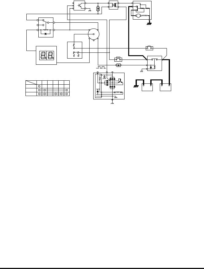
After Start
Once the engine has been started, the belt driven alternator (10) generates a current.
The output generated by the alternator (10) is a square wave pulse voltage through the "P" terminal and the frequency of the pulse voltage is proportional to the rotation of the alternator.
The starter controller (7) monitors the frequency of the output current. Once the frequency is equivalent to 500 rpm, it is sensed and the connection between "S" and "E" terminals and the connection between "B" and "PP" terminals are opened. As a result the rotation of the starter (9) is stopped. Once the engine is running, the starter (9) will not operate even if the starter switch (5) is moved to the start position, preventing possible damage to the starter.
Electrical System |
SP001038 |
Page 14 |
|
Operation of the Start Circuit (2) - Immediately After Start
|
|
|
|
7 |
|
|
8 |
|
9 |
|
|
|
|
|
|
N |
S |
|
D |
PP |
|
C |
|
|
|
|
|
|
P |
E |
|
C |
B |
|
B |
|
|
|
|
|
|
B |
11 |
|
|
|
|
|
|
||
|
|
|
|
|
|
|
|
|
|
|||
|
|
|
|
|
|
|
|
|
|
|
||
|
|
|
|
|
|
|
|
|
A |
|
|
|
|
87a |
|
|
|
|
|
|
|
|
|
|
|
|
|
|
30 |
|
|
|
|
|
|
|
|
|
|
87 |
|
|
|
|
|
|
|
|
|
|
|
|
85 |
|
86 |
ACC |
|
C |
|
|
|
|
|
|
|
|
|
|
|
|
|
|
|
|
|
|
|
|
|
|
|
|
B |
5 |
|
|
|
|
|
|
|
|
|
|
|
|
|
|
|
|
|
|
|
|
|
|
12 |
R2 |
|
BR |
|
|
|
|
|
|
|
|
|
|
R1 |
|
|
|
|
3 |
|
|
|
|
|
|
|
|
|
|
|
|
|
|
||
|
|
|
|
|
|
|
|
|
|
|
|
|
CN1-15 |
|
6 |
|
|
|
|
|
|
|
|
|
|
|
|
|
|
|
|
|
|
|
|
|
|
|
|
|
|
|
|
|
|
4 |
|
|
B |
|
A |
|
|
|
|
|
|
|
|
|
|
|
||
|
|
|
CN2-1 |
|
|
|
|
|
|
|
|
|
|
|
|
13 |
|
|
|
|
|
|
BR |
|
|
|
|
|
|
|
|
11 |
|
|
E |
|
|
|
|
|
|
|
|
|
R(I) P(R) |
|
|
|
|
|
|
|
|
|
|
|
|
B(B+) |
|
|
|
2 |
|
|
|
|
|
|
|
|
0.5 uF |
|
|
|
|
|
|
STARTER SWITCH CONNECTION |
|
|
B+ |
|
|
|
|
|
|
|||
|
|
|
|
|
|
|
|
|
||||
|
TML |
B |
BR R1 R2 C ACC |
|
|
I(L) |
|
|
|
|
|
|
PST |
|
|
|
|
|
|
|
|
|
|||
|
|
|
|
|
|
|
|
|
|
|||
OFF |
|
|
|
|
|
REG. |
|
|
- |
+ |
- |
+ |
|
|
|
|
|
TRIO DIODE |
|
10 |
|||||
ON |
|
|
|
|
|
|
|
|
|
|
|
|
|
|
|
|
|
F+ |
FIELD |
|
|
|
1 |
|
|
START |
|
|
|
|
F- |
|
|
|
|
|
||
|
|
|
|
E |
|
|
|
|
|
|
||
|
|
|
|
|
|
|
|
|
|
|
|
|
|
|
|
|
|
|
|
GRD |
|
|
|
|
FG007237 |
|
|
|
|
|
|
|
|
|
|
|
|
|
Figure 4 OPERATION OF START CIRCUIT (2) - IMMEDIATELY AFTER START
Reference |
Description |
|
Number |
||
|
||
|
|
|
1 |
Battery |
|
|
|
|
2 |
Battery Relay |
|
|
|
|
3 |
Fusible Link |
|
|
|
|
4 |
Circuit Breaker |
|
|
|
|
5 |
Starter Switch |
|
|
|
|
6 |
Fuse Box |
|
|
|
|
7 |
Starter Controller |
|
|
|
Reference |
Description |
|
Number |
||
|
||
|
|
|
8 |
Starter Relay |
|
|
|
|
9 |
Starter |
|
|
|
|
10 |
Alternator |
|
|
|
|
11 |
Diode |
|
|
|
|
12 |
Starter Relay 2 |
|
|
|
|
13 |
e-EPOS Controller |
|
|
|
Electrical System |
SP001038 |
|
Page 15 |

ENGINE PREHEATING SYSTEM
An air heater (8) is installed in the intake manifold of the engine. When the starter switcho (5) is turned "ON,"o the currentoflows from the battery (1) fusibleo link (3) fuse box (6) "B" oterminal of starter switch (5) "BR" terminalof starter switch (5)
"1-39" terminal of engine controller (12), causing ocurrent to flow though "1-16" terminal of engineo controller (12) "C and D" terminals ofopreheat relay (7) "1-04" terminals of engine controller (12) ground.
This current flow causes the coil in preheat relay (7) to be activated, closing contacts.
When the contacts of the preheat relay (7) are closed, the heating coils of the air heatingo device (8) are heatedo by current flowingo from the batteryo (1) battery relay (2) preheat relay
(7) air heater (8) ground.
The duration of the heating cycle depends on the temperature of engine coolant. The preheat indicator light in the instrument panel (9) will turn "ON" during preheating cycle.
The preheat relay (7) is controlled by the engine controller (12) and operates only at temperatures of 10°C (50°F) and below.
The longer the preheating period, the lower the temperature of coolant is.
Electrical System |
SP001038 |
Page 16 |
|

|
|
|
|
|
|
3 |
|
|
|
|
6 |
|
|
|
|
|
|
|
|
9 |
|
|
|
|
4 |
|
|
|
|
|
CN6-1,2 |
|
|
|
|
|
2 |
|
|
|
|
ACC |
|
C |
|
|
B |
A |
|
PREHEAT L5 |
CN7-4,5,6 |
|
|
|
|
|
|||
|
B |
5 |
|
|
|
|
|
||
|
|
R2 |
|
|
|
|
BR |
|
|
|
|
|
|
|
|
|
|
|
|
|
|
|
R1 |
BR |
10 |
|
E |
|
|
|
|
|
|
|
|
|
|
|
|
|
CN4-4,5,6 |
|
|
|
|
|
|
|
|
|
CN2-1 |
|
|
|
|
|
|
|
|
|
|
|
|
|
|
- |
+ |
- |
+ |
11 |
|
|
|
|
|
|
1 |
|
|
|
C |
B |
|
|
|
|
|
|
|
|
|
|
|
|
|
|
|
||
|
|
200A |
|
- |
|
|
|
|
|
|
|
|
|
|
|
|
|
|
|
|
1-34,35 |
7 |
|
|
|
STARTER SWITCH CONNECTION |
|||
|
|
|
|
|
|
|
|
|
|
|
1-40 |
|
|
|
PST |
TML |
B BR R1 |
R2 |
C ACC |
|
|
|
|
|
|||||
|
1-13 |
|
|
(1) |
OFF |
|
|
|
|
|
D |
H |
+ |
|
|
|
|||
|
|
|
|
|
|
|
|||
|
|
|
|
ON |
|
|
|
|
|
|
1-07 |
|
|
|
|
|
|
|
|
START
12
FG007137
Figure 5 ENGINE PREHEAT CIRCUIT
Reference |
Description |
|
Number |
||
|
||
|
|
|
1 |
Battery |
|
|
|
|
2 |
Battery Relay |
|
|
|
|
3 |
Fusible Link |
|
|
|
|
4 |
Circuit Breaker |
|
|
|
|
5 |
Starter Switch |
|
|
|
|
6 |
Fuse Box |
|
|
|
Reference |
Description |
|
Number |
||
|
||
|
|
|
7 |
Preheat Relay |
|
|
|
|
8 |
Air Heater |
|
|
|
|
9 |
Preheat Indicator Light |
|
|
|
|
10 |
Diode |
|
|
|
|
11 |
e-EPOS Controller |
|
|
|
|
12 |
Engine Controller |
|
|
|
Electrical System |
SP001038 |
|
Page 17 |
ENGINE STOP
When starter switch (5) is turned "ON" the engine controller (8) is activated. The engine controller monitors and controls the engine including the injector solenoid (9). It controls the fuel deliver rate and the injection timing for each cylinder.
NOTE: There is an individual injector solenoid (9) for each of the six cylinders. Only one soleniod is shown in Figure 7.
When starter switch (5) is turned "OFF," the engine controller stops suppling power to the injector solenoid (9). This stops fuel from being injexted into the engine cylinder, thus stopping the engine.
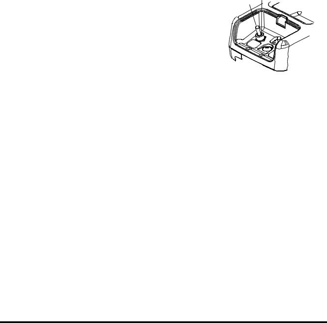
In the event that the engine can be shut down using the starter switch (5), an emergency stop switch (10) is provided to shut down engine. To activate the emergancy stop switch, move it to the "I" (EMERGENCY STOP) position.
The emergency stop switch (10) is in its "O" (OFF) position during normal operation. The switch must be moved and held in the "I" (EMERGENCY STOP) position until the engine stops. When released it will automatically move back to the "O" (OFF) position.
O I
FG001344
Figure 6 ENGINE EMERGENCY STOP
SWITCH
Electrical System |
SP001038 |
Page 18 |
|
STARTER SWITCH CONNECTION
PST |
TML |
B BR |
R1 R2 |
C ACC |
|
OFF
ON
START
8
6
0.5G
|
|
|
|
|
3 |
|
|
|
|
|
ACC |
|
C |
|
|
|
|
|
|
10 |
B |
|
5 |
|
|
|
|
2 |
R2 |
|
BR |
4 |
|
2 |
|
1-19 |
3 |
|
|
|
||||
R1 |
|
|
|
|||||
1-45 |
|
|
|
B |
|
|
A |
|
|
|
|
|
|
|
|||
1-39 |
|
|
|
|
BR |
|
|
|
|
|
|
|
|
E |
|
|
|
|
|
|
|
|
7 |
|
|
|
|
|
9 |
|
|
|
|
|
|
|
|
|
|
|
- |
+ |
- |
+ |
Figure 7 ENGINE STOP CIRCUIT
Reference |
Description |
|
Number |
||
|
||
|
|
|
1 |
Battery |
|
|
|
|
2 |
Battery Relay |
|
|
|
|
3 |
Fusible Link |
|
|
|
|
4 |
Circuit Breaker |
|
|
|
|
5 |
Starter Switch |
|
|
|
|
1 |
|
|
FG001473 |
|
|
|
|
Reference |
Description |
|
Number |
||
|
||
|
|
|
6 |
Fuse Box |
|
|
|
|
7 |
Diode |
|
|
|
|
8 |
Engine Controller |
|
|
|
|
9 |
Injector Solenoid |
|
|
|
|
10 |
Emergency Stop Switch |
|
|
|
Electrical System |
SP001038 |
|
Page 19 |
CHARGING SYSTEM
When the starter switch (5) is turned to the "ON" position, an initial excited current flows to the field coil of the alternator (7) through the battery relay (2) and circuit breaker (4). When the engine is started from this condition the alternator (7) starts charging. Theo current flows fromo the "B(B+)" terminalo of alternator (7) circuit breaker (4) battery relay (2) battery
(1).
The alternator also supplies electric current to other electrical components. When the alternator (7) startsoto operate,oa current flows from the "R(I)" terminal of alternator diode (8) battery relay (2) coil securing a path for the charging current to the battery (1). Thus preventing the possibility of a high voltage build up and possible damage to the electric system.
ACC |
C |
B5
|
|
|
|
R2 |
BR |
|
|
|
|
|
|
|
|
|
|
|
|
|
0.5G |
|
|
|
|
|
|
|
|
|
R1 |
|
|
|
|
|
|
|
|
|
|
|
|
|
|
|
|
|
|
|
|
6 |
|
|
|
|
|
3 |
|
|
|
|
|
|
|
|
|
|
|
|
|
|
|
|
|
|
|
|
8 |
|
|
|
|
2 |
|
|
|
|
|
|
|
|
4 |
|
|
|
|
|
|
|
|
|
|
|
|
|
|
|
|
|
|
|
|
|
|
|
|
B |
|
A |
|
|
|
|
|
|
|
|
|
BR |
|
|
|
|
|
|
|
|
|
|
|
E |
|
|
|
|
|
|
|
|
8 |
|
|
|
|
|
|
|
|
|
|
|
|
|
|
- |
+ |
- |
+ |
|
|
|
|
|
R(I) |
P(R) |
B(B+) |
12V 100AH |
|
12V 100AH |
|
|
|
|
|
|
|
|
1 |
|
|||
STARTER SWITCH CONNECTION |
|
|
0.5 uF |
|
|
|
|
|
|||
|
|
B+ |
|
|
|
|
|
|
|||
PST |
TML |
B BR R1 R2 C |
ACC |
|
I(L) |
|
|
|
|
|
|
|
|
|
|
|
|
|
|
|
|||
OFF |
|
|
|
|
REG. TRIO DIODE |
|
7 |
|
|
|
|
ON |
|
|
|
|
F+ |
|
FIELD |
|
|
|
|
|
|
|
|
|
|
|
|
|
|
|
|
START |
|
|
|
|
F- |
|
|
|
|
|
|
|
|
|
|
|
E |
|
|
|
|
|
|
|
|
|
|
|
|
|
GRD |
|
|
|
|
FG007238
Figure 8 CHARGING CIRCUIT
Reference |
Description |
|
Number |
||
|
||
|
|
|
1 |
Battery |
|
|
|
|
2 |
Battery Relay |
|
|
|
|
3 |
Fusible Link |
|
|
|
|
4 |
Circuit Breaker |
|
|
|
Reference |
Description |
|
Number |
||
|
||
|
|
|
5 |
Starter Switch |
|
|
|
|
6 |
Fuse Box |
|
|
|
|
7 |
Alternator |
|
|
|
|
8 |
Diode |
|
|
|
Electrical System |
SP001038 |
Page 20 |
|

MONITORING SYSTEM
1
+2
-
|
|
|
|
5 |
7 |
|
|
|
|
8 |
|
|
|
|
|
4 |
|
|
|
|
|
|
R |
|
|
|
|
|
B |
|
|
|
|
|
E |
|
|
CHECK |
|
|
|
|
|
|
|
3 |
9 |
02/05 [MO] 11:30 |
|
|
|
||
|
E |
F |
|
|
|
C |
H |
C |
H |
|
10 |
|
|
||||
E/G SPEED |
1700 |
RPM |
6 |
|
|
|
|
|
|
|
|
1 |
2 |
3 |
4 |
|
|
|
|
|
ESC |
|
|
|
|
|
|
|
11 |
5 |
6 |
7 |
8 |
|
|
13
12
FG000547
Figure 9
Reference |
Description |
|
Number |
||
|
||
|
|
|
1 |
Instrument Panel |
|
|
|
|
2 |
Battery |
|
|
|
|
3 |
Light Switch |
|
|
|
|
4 |
Return Filter Switch |
|
|
|
|
5 |
Pilot Filter Switch |
|
|
|
|
6 |
e-EPOS Controller |
|
|
|
|
7 |
Alternator |
|
|
|
Reference |
Description |
|
Number |
||
|
||
|
|
|
8 |
Warning Buzzer |
|
|
|
|
9 |
Pump Discharge Pressure |
|
Sensor |
||
|
||
|
|
|
10 |
Hydraulic Oil Temperature |
|
Sensor |
||
|
||
|
|
|
11 |
Fuel Sensor |
|
|
|
|
12 |
Air Cleaner Indicator |
|
|
|
|
13 |
Engine Controller |
|
|
|
The monitoring system displays the various data and warning signals onto the instrument panel by processing the information gathered from the e-EPOS controller. It displays information selected by the operator.
Electrical System |
SP001038 |
|
Page 21 |
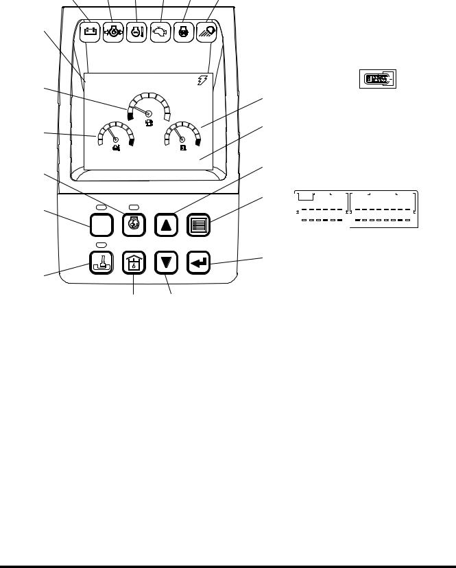
Instrument Panel
7 |
8 |
9 |
10 |
11 |
12 |
5 |
|
|
CHECK |
|
|
1 |
02/05 [MO] 11:30 |
|
||
|
|
|
|
|
|
|
E |
F |
|
2 |
|
|
|
|
|
C |
H |
C |
H |
|
E/G SPEED |
1700 |
RPM |
|
15 |
|
|
|
|
13 |
|
|
|
|
|
1 |
2 |
3 |
4 |
|
|
|
|
ESC |
14 |
5 |
6 |
7 |
8 |
16 18
Figure 10
6 
 1
1
3
4
< CONNECTOR AND TERMINAL NO.>
17
AMP 040 28P
19 |
|
|
|
|
|
|
|
|
|
|
|
|
|
|
|
|
|
|
|
|
|
|
|
|
|
|
|
|
|
|
|
|
|
|
|
|
|
|
|
6 |
5 |
|
4 |
|
3 |
|
2 |
|
1 |
|
|
8 |
|
7 |
|
6 |
|
5 |
4 |
|
3 |
|
2 |
|
1 |
|
|||||||
|
|
11 |
10 |
|
9 |
|
8 |
|
7 |
|
|
16 |
15 |
14 |
13 |
12 |
11 |
10 |
|
9 |
|
|||||||||||||||
|
|
12 |
|
|
|
|
|
|
|
|||||||||||||||||||||||||||
|
|
|
|
|
|
|
|
|
|
|
|
|
|
|
|
|
|
|
|
|
|
|
|
|
|
|
|
|
|
|
|
|
||||
|
|
|
|
|
|
|
|
|
|
|
|
|
|
|
|
|
|
|
|
|
|
|
|
|
|
|
|
|
|
|
|
|
|
|
|
|
|
|
|
|
|
|
|
|
|
|
|
|
|
|
|
|
|
|
|
|
|
|
|
|
|
|
|
|
|
|
|
|
|
||||
|
|
|
|
|
|
|
(CN7) |
|
|
|
|
|
|
|
|
|
|
|
|
|
|
(CN6) |
|
|
|
|
|
|||||||||
20 |
|
|
|
|
|
|
|
|
|
|
|
|
|
|
|
|
|
|
|
|
|
|
|
|
|
|
|
|
|
|
|
|
|
|
|
|
FG000548
Electrical System |
SP001038 |
Page 22 |
|

|
Gauges |
|
Warning Lights |
|
Mode Selector Switches |
||
|
|
|
|
|
|
|
|
1. |
Fuel Gauge |
|
7. |
Charge Warning Light |
13. |
Power Mode Selector Switch |
|
2. |
Engine Coolant Temperature |
8. |
Engine Oil Pressure Warning |
|
and Indicator |
||
|
|
||||||
|
Gauge |
|
|
Light |
|
14. |
Work Mode Selector Switch |
3. |
Hydraulic Oil |
Temperature |
9. |
Coolant |
Temperature |
|
and Indicator |
|
|
||||||
|
Gauge |
|
|
Warning Light |
|
15. |
Auto Idle Switch and |
4. |
Multifunction |
Gauge and |
10. |
Engine Check Warning Light |
|
Indicator |
|
|
|
||||||
|
Letter Information Area |
11. |
Preheat Indicator Light |
16. |
Flow Adjusting Switch |
||
|
|
|
|
|
|||
5. |
Digital Clock |
|
12. Work Light Indicator Light |
17. |
Up Button Switch |
||
|
|
|
|
|
|||
6. |
Hour Meter |
|
|
|
|
18. |
Down Button Switch |
|
|
|
|
|
|
19. |
Display Selector Switch |
|
|
|
|
|
|
20. |
Selector Button Switch |
|
|
|
|
|
|
|
|
When the engine starter switch is turned to the "I" (ON) position, all gauge bands, switch/button indicator lights and indicator/ warning lights will turn "ON" and the alarm buzzer will sound about two seconds.
During this functional check, a LOGO will appear on the multi function gauge in the graphic information area
Electrical System |
SP001038 |
|
Page 23 |

Monitoring System Schematic
1
CN6-1
|
|
|
|
|
3 |
ILL. |
CN6-3 |
|
|
|
|
|
|
|
|
|
|
|
CN6-2 |
+ |
|
|
|
|
|
|
|
|
|
L1 |
CN6-12 |
- |
|
|
|
|
|
|
|
|
|
L2 |
CN6-11 |
|
2 |
|
|
|
|
|
|
||
L3 |
|
|
|
|
4 |
|
|
|
|
|
|
L4 |
|
|
|
|
R2 B |
L5 |
CN6-9 |
|
|
|
|
|
|
|
|
|
|
|
CN6-10 |
|
|
|
|
L6 |
|
|
|
|
14 |
|
|
|
|
|
|
WARNING LAMP |
|
|
|
CN2-1 |
|
|
|
|
|
|
|
L1 : CHARGE |
|
|
|
|
|
L2 : ENG OIL PRESS |
|
|
|
|
|
L3 : W/T OVER HEAT |
|
|
|
|
|
L4 : E/G WARNING |
|
|
|
|
|
L5 : PREHEAT |
|
|
+ |
|
|
|
|
|
|
|
|
L6 : WORK LAMP |
|
5 SIG |
CN3-1 |
|
|
|
|
|
|||
|
|
CN3-2 |
|
||
LCD DISPLAY PANEL |
|
|
- |
|
|
|
|
|
|
||
WATER TEMPERATURE |
|
|
|
|
|
FUEL LEVEL |
|
|
+ |
|
|
|
|
|
|
|
|
|
|
6 |
SIG |
CN3-3 |
|
|
|
|
|
||
GRAPHIC DISPLAY |
|
|
CN3-4 |
|
|
|
|
- |
|
||
|
|
|
|
|
|
|
CN7-4 |
|
|
CN4-4 |
|
|
CN7-5 |
|
|
CN4-5 |
CAN A |
|
|
|
|
|
|
|
CN7-6 |
|
|
CN4-6 |
|
CN4-3 GND
21 CN4-2 RxD
CN4-1 TxD
1-35 |
|
|
|
1-34 |
1 |
|
|
|
|
||
|
2 |
|
|
|
3 |
|
|
1-53 |
4 |
20 |
|
1-52 |
|||
5 |
|
||
|
|
||
|
6 |
|
|
1-56 |
14 |
|
|
|
|
CN5-2 |
|
R(I) |
|
CN2-14 |
13
Figure 11
19
17
16 B
BR
E
A
18
15
CN5-7
9
CN2-17
10
CN2-18
|
11 |
CN5-3 |
|
|
12 |
CN3-7 |
|
CN3-8 |
8 |
CN3-9 |
|
CN3-10 |
7 |
FG007141
Electrical System |
SP001038 |
Page 24 |
|

Reference |
Description |
|
Number |
||
|
||
|
|
|
1 |
Instrument Panel |
|
|
|
|
2 |
Pilot Buzzer |
|
|
|
|
3 |
Light Switch |
|
|
|
|
4 |
Starter Switch |
|
|
|
|
5 |
Front Pump Pressure Sensor |
|
|
|
|
6 |
Rear Pump Pressure Sensor |
|
|
|
|
7 |
Hydraulic Oil Temperature |
|
|
Sensor |
|
|
|
|
8 |
Fuel Sensor |
|
|
|
|
9 |
Pedal Pressure Switch (Optional) |
|
|
|
|
10 |
Air Cleaner Indicator |
|
|
|
Reference |
Description |
|
Number |
||
|
||
|
|
|
11 |
Pilot Filter Switch |
|
|
|
|
12 |
Return Filter Switch |
|
|
|
|
13 |
Alternator |
|
|
|
|
14 |
e-EPOS Controller |
|
|
|
|
15 |
Battery |
|
|
|
|
16 |
Battery Relay |
|
|
|
|
17 |
Circuit Breaker |
|
|
|
|
18 |
Fusible Link |
|
|
|
|
19 |
Fuse Box |
|
|
|
|
20 |
Check Connector |
|
|
|
|
21 |
Engine Controller |
|
|
|
Electrical System |
SP001038 |
|
Page 25 |
OPERATION
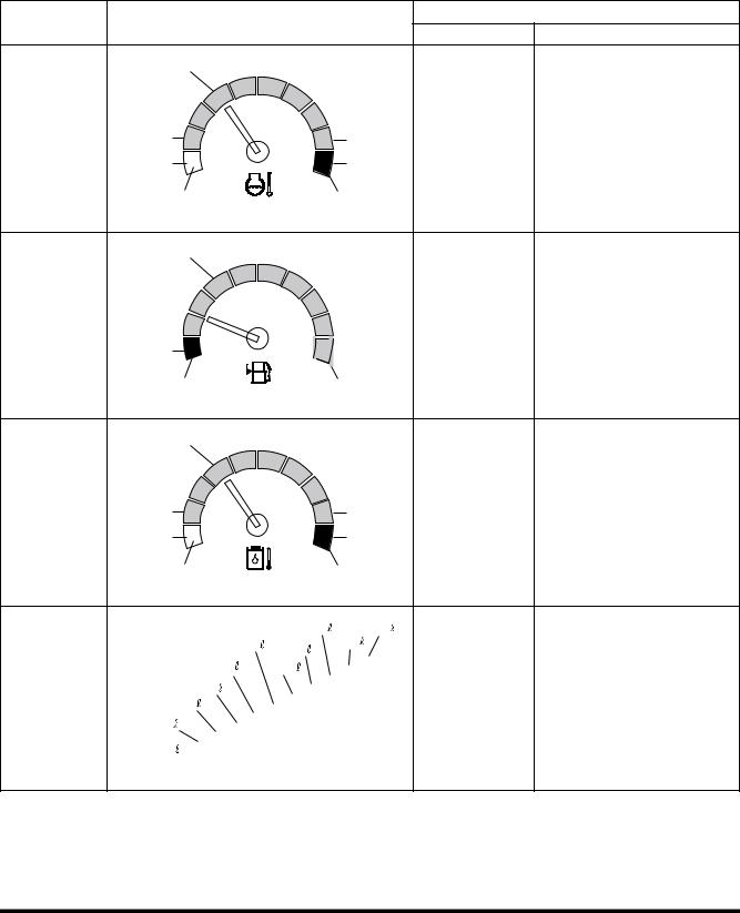
Instruments
Function |
|
|
Display |
|
Sensor Specification |
|
|
|
|
Input Terminal |
Input Specification |
||
|
|
|
|
|
||
|
Blue |
|
|
|
|
|
Coolant |
61°C |
|
|
102°C |
ECU-CAN |
|
Temperature |
|
|
Communication |
|
||
|
|
|
|
|
||
|
41°C |
C |
H |
107°C |
|
|
|
|
|
|
|
||
|
White |
|
|
Red |
|
|
|
|
|
|
FG000550 |
|
|
Blue |
|
|
|
|
|
|
|
CN3-7 |
1/10 LCD (Red Zone) |
Fuel Level |
|
|
Blinking o over 5K ohms |
|
|
|
|
||
1/10 |
|
|
CN3-8 |
FULL o under 525 ohms |
E |
F |
|
||
|
|
|
||
Red |
|
|
Full |
|
|
|
|
FG000552 |
|
|
|
Blue |
|
|
|
|
|
|
|
|
|
|
|
|
|
|
|
|
|
|
|
|
|
|
|
40°C (104°F) o 1,397 ohms |
|
|
|
|
|
|
|
|
|
|
|
|
|
|
|
|
|
|
|
|
|
|
|
|
|
|
|
50°C (122°F) o |
1,139 ohms |
|
|
|
|
|
|
|
|
|
|
|
|
|
|
|
|
|
|
|
|
|
|
|
|
|
|
||
Hydraulic |
Oil |
50°C |
|
|
|
|
|
|
|
|
|
|
|
|
|
|
|
|
|
|
|
|
|
|
CN3-9 |
60°C (140°F) o |
881 ohms |
Temperature |
|
|
|
|
|
|
|
|
|
|
|
|
|
|
|
|
|
|
|
94°C |
94°C (201°F) o 190 ohms |
||||||
40°C |
|
|
|
|
|
|
|
|
|
|
|
|
|
|
|
|
|
|
|
|
|
|
CN3-10 |
||||
|
|
|
|
|
|
|
|
|
|
|
|
|
|
|
|
|
|
|
|
|
|
||||||
|
|
|
C |
|
|
|
H |
|
|
|
96°C |
96°C (205°F) o 177 ohms |
|||||||||||||||
|
|
|
|
|
|
|
|
|
|
|
|
|
|
||||||||||||||
|
|
White |
|
|
|
|
|
|
|
|
Red |
(When reading increase) |
|||||||||||||||
|
|
|
|
|
|
|
|
|
|
|
|
|
|
|
|
|
|
|
|
FG000551 |
|||||||
|
|
|
|
|
|
|
|
|
|
|
|
|
|
|
|
|
|
|
|
48.5 l/min o 610 mA |
|||||||
|
|
|
|
|
|
|
|
|
|
|
108 |
114 |
|||||||||||||||
|
|
|
|
|
|
|
|
|
|
|
57 l/min o 583 mA |
||||||||||||||||
|
|
|
90 |
106.5 |
|
|
|
114 |
|
|
|||||||||||||||||
|
|
|
|
|
|
|
|
|
|
|
|
|
|||||||||||||||
|
|
|
78.5 |
|
|
|
96.5 |
|
|
|
|
|
|
|
|
|
|
(Output |
66 l/min o 555 mA |
||||||||
|
|
|
|
|
|
|
|
|
|
|
|
|
|
|
|
||||||||||||
Flow |
|
66 |
69 |
|
|
|
|
|
|
|
|
|
|
|
|
|
|
|
|
|
|
|
Terminal) |
78.5 l/min o 466 mA |
|||
|
|
|
|
|
|
|
|
|
|
|
|
|
|
|
|||||||||||||
|
|
|
|
|
|
|
|
|
|
|
|
|
|
|
|
|
|
|
|
CN1-19 |
|||||||
Adjusting |
|
|
|
|
|
|
|
|
|
|
|
|
|
|
|
|
|
|
|
|
|
|
|
||||
|
57 |
|
|
|
|
|
|
|
|
|
|
|
|
|
|
|
|
|
|
|
|
|
|
(Default Set) |
|
||
|
|
|
|
|
|
|
|
|
|
|
|
|
|
|
|
|
|
|
|
|
|
|
|
|
|
||
|
|
|
|
|
|
|
|
|
|
|
|
|
|
|
|
|
|
|
|
|
|
|
|
|
|
||
|
|
48.5 |
|
|
|
|
|
|
|
|
|
|
|
|
|
|
|
|
|
|
|
|
|
|
CN1-20 |
108 l/min o 343 mA |
|
|
|
|
|
|
|
|
|
|
|
|
|
|
|
|
|
|
|
|
|||||||||
|
|
|
|
|
|
|
|
|
|
|
|
|
|
|
|
|
|
|
|
|
|
|
|
|
|||
|
|
(None) |
|
|
|
|
|
|
|
|
|
|
|
|
|
|
|
|
|
|
|
|
|
|
|
114 l/min o 290 mA |
|
|
|
|
|
|
|
|
|
|
|
|
|
|
|
|
|
|
|
|
|
|
|
FG009964 |
|||||
|
|
|
|
|
|
|
|
|
|
|
|
|
|
|
|
|
|
|
|
|
|
|
|
||||
Electrical System |
SP001038 |
Page 26 |
|

Function |
Display |
Sensor Specification |
||
|
|
|||
Input Terminal |
Input Specification |
|||
|
|
|||
|
|
|
|
|
|
|
|
N = 162 f / 60 |
|
Tachometer |
E/G SPEED 1700 RPM |
ECU-CAN |
N = Engine speed (rpm) |
|
Communication |
f = Frequency of engine |
|||
|
|
|||
|
|
|
||
|
|
|
speed sensor (Hz) |
|
|
FG000049 |
|
|
|
|
|
|
|
|
Voltmeter |
BATTERY 28.0 VOLT |
CN2-14 |
0 - 32 VDC |
|
|
FG000050 |
|
|
|
|
|
|
|
|
Main pump |
|
CN3-1 |
|
|
discharge |
FRONT PUMP 320 BAR |
|
||
|
|
|||
pressure |
CN3-2 |
|
||
|
|
|||
(front pump) |
|
|
||
|
|
|
||
|
|
|
V = 0.00816 x P + 1.0 |
|
|
FG000051 |
|
|
|
|
|
|
V: Sensor output voltage (V) |
|
|
|
|
||
|
|
|
P: Displayed pressure (Bar) |
|
Main pump |
|
CN3-3 |
|
|
discharge |
REAR PUMP 313 BAR |
|
||
|
|
|||
pressure |
CN3-4 |
|
||
|
|
|||
(rear pump) |
|
|
||
|
|
|
||
|
FG000052 |
|
|
|
|
|
|
|
|
Electrical System |
SP001038 |
|
Page 27 |
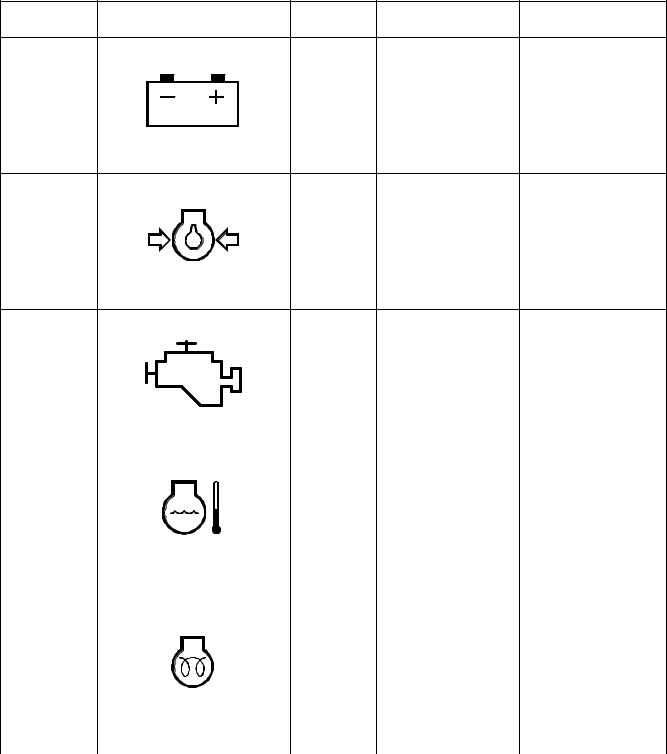
WARNING AND INDICATOR
LIGHTS
Indication of Warning Lights
Input
Description Symbol Operation Remarks
Terminal
|
|
It lights in case of no |
|
|
|
|
charge [voltage of |
Normally, it lights |
|
|
|
"R(I)" terminal is |
||
|
|
when starting engine |
||
Charge |
CN2 - 14 |
below 12 ±1V] or |
||
and is out after engine |
||||
|
|
overcharge [voltage |
||
|
|
starts. |
||
|
|
of "R(I)" terminal is |
||
|
|
|
||
|
HAOA610L |
above 33(V)]. |
|
|
|
|
|
||
|
|
|
After starting engine, |
|
Engine Oil |
ECU-CAN |
It lights when engine |
if engine oil pressure |
|
Communic |
oil pressure is below |
is insufficient after 8 |
||
Pressure |
||||
ation |
the reference. |
seconds, a warning |
||
|
||||
|
|
|
buzzer will sound. |
|
|
HAOA620L |
|
|
Engine |
|
|
|
|
|
|
|
ECU-CAN |
It lights in case of |
|
CHECK |
|
|
||||||||
|
|
Communic |
failure in engine |
|
||||||
Check |
|
|
|
|||||||
|
|
|
|
|
|
|
ation |
system. |
|
|
|
|
|
|
|
|
|
|
|
||
|
|
|
|
|
|
|
|
FG000045 |
|
|
|
|
|
|
|
|
|
|
|
|
|
|
|
|
|
|
|
|
|
|
|
|
|
|
|
|
|
|
|
|
|
It lights when engine |
|
Coolant |
|
|
|
|
|
|
|
ECU-CAN |
coolant temperature |
|
|
|
|
|
|
|
|
Communic |
sensor resistant is |
|
|
Temperature |
|
|
|
|
|
|
|
|
||
|
|
|
|
|
|
|
ation |
below about 128 |
|
|
|
|
|
|
|
|
|
|
|
||
|
|
|
|
|
|
|
|
|
ohms. |
|
|
|
|
|
|
|
|
|
HAOD350L |
|
|
|
|
|
|
|
|
|
|
|
|
|
|
|
|
|
|
|
|
|
|
|
Preheating period |
|
|
|
|
|
|
|
|
|
It lights during |
depends on coolant |
|
|
|
|
|
|
|
|
|
temperature. |
|
|
|
|
|
|
|
|
|
|
preheating ("CN5-2" |
|
|
|
|
|
|
|
|
|
|
No preheating at |
|
|
|
|
|
|
|
|
|
|
terminal voltage is |
|
|
|
|
|
|
|
|
|
|
above 10°C |
|
Preheating |
|
|
|
|
|
|
|
CN5-2 |
below 2V) and turns |
|
|
|
|
|
|
|
|
|
|||
|
|
|
|
|
|
|
|
|
"OFF" after |
10 sec preheating at |
|
|
|
|
|
|
|
|
|
completion of |
|
|
|
|
|
|
|
|
|
|
5°C |
|
|
|
|
|
|
|
|
|
|
preheating. |
|
|
|
|
|
|
|
|
|
HAOA639L |
|
|
|
|
|
|
|
|
|
|
|
|
20 sec preheating at |
|
|
|
|
|
|
|
|
|
|
below 0°C |
|
|
|
|
|
|
|
|
|
|
|
|
|
|
|
|
|
|
|
|
|
|
|
|
|
|
|
|
|
|
|
|
|
Electrical System |
|
|
|
|
|
|
|
|
|
SP001038 |
Page 28 |
|
|
|
|
|
|
|
|
|
|
 Loading...