


Machine Tools
Installation Manual
DBC 130

DBC 130II |
DBC130II ISE41 |
|
|
Table of Contents
For enhanced performance, this installation manual is subject to change without notice |
|
|
Table of Contents .................................................................................................................. |
1 |
|
1. Installation Site.................................................................................................................. |
4 |
|
2. Foundation work ............................................................................................................... |
9 |
|
2.1 |
Foundation work timing and post checkpoints ............................................................... |
9 |
2.2 |
Foundation work for installing the machine ................................................................... |
9 |
3. Transportation ................................................................................................................. |
15 |
|
4. What's included............................................................................................................... |
16 |
|
4.1 |
Table Bed Ass’y.......................................................................................................... |
16 |
4.2 |
Column Bed Ass’y ...................................................................................................... |
18 |
4.3 |
Column Body Ass’y .................................................................................................... |
20 |
4.4 |
Spindle Head Ass’y..................................................................................................... |
21 |
4.5 |
Duct Ass’y .................................................................................................................. |
22 |
4.6 |
Coolant Tank, Chip Bucket, Chip Conveyor, TSC Ass’y, T/F(Option)............................ |
23 |
4.7 |
Tool Magazine Ass’y (Option) ..................................................................................... |
24 |
4.8 |
Semi Splash Guard – Operator Part (Option) .............................................................. |
25 |
4.9 |
Semi Splash Guard – Magazine Part (Option)............................................................. |
27 |
4.10 Semi Splash Guard – Table Part (Option).................................................................. |
28 |
|
4.11 List of tools related to the foundation work (1) ........................................................... |
30 |
|
4.12 List of tools related to the foundation work (2) ........................................................... |
31 |
|
4.13 BOLT KIT Shipping LIST........................................................................................... |
33 |
|
5. Installing the machine temporarily ................................................................................ |
36 |
|
5.1 |
Temporary installation of the column bed (Z-axis bed) assembly ................................. |
36 |
5.2 |
Temporary installation of the table bed (X-axis bed) assembly..................................... |
39 |
5.3 |
Temporary Installation of ATC Base ............................................................................ |
42 |
6. Second Round of Grout Injection .................................................................................. |
44 |
|
6.1 |
Checkpoints before injecting grout.............................................................................. |
44 |
6.2 |
Selection of Grout ...................................................................................................... |
44 |
6.3 |
Blending the grout mixture.......................................................................................... |
45 |
6.4 Injecting the grout mixture........................................................................................... |
46 |
|
6.5 |
Curing the surface of grout ......................................................................................... |
47 |
7. Assembling the main unit............................................................................................... |
48 |
|
7.1 |
Installing the column................................................................................................... |
48 |
7.2 |
Installing the spindle head .......................................................................................... |
50 |
1

|
|
DBC 130II |
DBC130II ISE41 |
|
|
|
|
|
|
7.3 |
Installing the hydraulic power unit, electric cabinet, OP box and ducts |
........................ 53 |
||
7.4 |
Wiring........................................................................................................................ |
55 |
||
7.5 |
Connecting the hydraulic and air hoses...................................................................... |
59 |
||
7.6 |
Connecting the tool magazine wires and hydraulic hoses ........................................... |
60 |
||
8. Removing the transit clamps......................................................................................... |
61 |
|||
9. Checking and fueling the oil tanks................................................................................ |
62 |
|||
9.1 |
Hydraulic tank............................................................................................................ |
62 |
||
9.2 |
Oil Cooler Tank .......................................................................................................... |
62 |
||
9.3 Table ......................................................................................................................... |
62 |
|||
9.4 |
Lub. Tank................................................................................................................... |
62 |
||
9.5 |
Spindle Air Oil Tank.................................................................................................... |
63 |
||
9.6 Air Service Unit Oiler Tank.......................................................................................... |
63 |
|||
9.7 |
Spindle Head Air Filter Unit Oiler Tank........................................................................ |
63 |
||
10. Connecting the main power and air sources ............................................................. |
64 |
|||
10.1 |
Connect the main power source............................................................................... |
64 |
||
10.2 |
Connecting the main air source................................................................................ |
64 |
||
11. Power On........................................................................................................................ |
66 |
|||
12. Checking the pressure on each unit........................................................................... |
67 |
|||
13. Assembling and adjusting the Y axis.......................................................................... |
69 |
|||
13.1 |
Installing the ball screw nut in the Y axis................................................................... |
69 |
||
13.2 |
Installing the Y-axis taper gib and back plate gib....................................................... |
69 |
||
13.3 |
Installing the reference gib ....................................................................................... |
70 |
||
13.4 |
Installing the ball screw nut ...................................................................................... |
70 |
||
14. Machine Leveling.......................................................................................................... |
71 |
|||
15. Precision Accuracy & Correction................................................................................ |
77 |
|||
15.1 |
Straightness of Z axis............................................................................................... |
79 |
||
15.2 |
Straightness of X Axis .............................................................................................. |
80 |
||
15.3 |
Straightness of Y Axis .............................................................................................. |
81 |
||
15.4 |
Straightness of Pallet Deck ...................................................................................... |
82 |
||
15.5 |
Squareness between coordinate axes...................................................................... |
83 |
||
15.6 |
Parallelism of movement to X/Z axis, parallelism of pallet deck, and shaking of index |
|||
table |
................................................................................................................................ |
86 |
||
15.7 |
Squareness in division of index table........................................................................ |
89 |
||
15.8 |
Parallelism of the X-axis movement for the T-slot ..................................................... |
90 |
||
15.9 |
Parallelism between center line of spindle and movement of Z-axis .......................... |
92 |
||
15.10 Run-out on the spindle ........................................................................................... |
94 |
|||
15.11 Movement of spindle in the Z-axis direction ............................................................ |
94 |
|||
16. Resetting the reference point for each axis ............................................................... |
95 |
|||
2

DBC 130II |
DBC130II ISE41 |
|
|
16.1 |
Resetting the reference point for the W axis (W-axis stroke : 700mm) ....................... |
95 |
|
16.2 |
Resetting the reference point for the X axis (X-axis stroke: 3000mm) ........................ |
96 |
|
16.3 |
Resetting the reference point for the Z axis (Z-axis stroke: 1600mm) ........................ |
97 |
|
16.4 |
Resetting the reference point for the Y axis (Y-axis stroke: 2000mm) ........................ |
99 |
|
17. Adjusting ATC.............................................................................................................. |
|
100 |
|
17.1 ATC installation & leveling....................................................................................... |
|
100 |
|
17.2 |
Carriage Magazine Side Home Position Setting ...................................................... |
|
102 |
17.3 |
Setting the reference point for the tool magazine pot............................................... |
|
106 |
17.4 |
Fine-tuning the spindle side of the changer arm ...................................................... |
|
110 |
17.5 |
Setting Parameter #7 & Changer Movement ........................................................... |
|
112 |
18. Installing the covers.................................................................................................... |
|
113 |
|
18.1 |
Installing the table bed covers................................................................................. |
|
113 |
18.2 |
Installing the column bed covers............................................................................. |
|
114 |
18.3 |
Installing the column covers.................................................................................... |
|
115 |
18.4 |
Installing the semi splash guard (in the table side) .................................................. |
|
116 |
18.5 |
Installing the semi splash guard (in the operator side)............................................. |
|
117 |
18.6 |
Installing the semi splash guard (in the chip conveyor side) .................................... |
|
118 |
19. Installation Complete .................................................................................................. |
|
119 |
|
3
DBC 130II |
DBC130II ISE41 |
|
|
1.Installation Site
1)Do not install the machine in a place of a high temperature difference or in areas that are exposed to dust or direct sunlight, and consider the ventilation condition. Besides, it is recommended to select a place of less vibration. However, if it's inevitable, take appropriate actions (reinforced foundation, reinforced ground, and dustproof screen, etc) to prevent the machine from being affected by the vibration .
2)The minimum bearing power of soil that is required to install the machine is 10 tons/m².
3)A 20-ton crane with a lifting performance of 8m must be equipped at the installation site. The installation personnel should take into consideration the dynamic relation between crane and foundation.
▪If a crane meeting the above specification is not available, use alternatives such as a car crane, large forklift, etc., for moving the machine.
4)When determining the installation site, refer to the machine layout diagram to secure room for installing the assemblies (ATC, electric cabinet, hydraulic tank, chip conveyor, etc) as well as enough room for repair (so that the doors are open/closed without interruption). Besides, secure enough room between machines to facilitate the installation work of the chip conveyor.
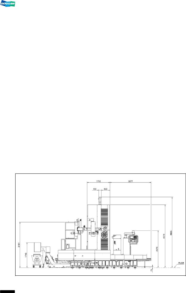
5)Refer to the layout diagram below. (For reference Only)
The below diagram is a standard machine layout for reference. The actual layout may differ due to engineering changes or application of client specifications. Refer to the layout diagram that is specific to the machine to install.
Ref 1) : Front View
4

DBC 130II |
DBC130II ISE41 |
|
|
|
|
|
|
Ref 2) : Right View |
|
|
|
|
|
|
|
|
|
|
|
Ref 3) : Top View
5

DBC 130II DBC130II ISE41
Ref 4) : Front view of machine to install semi splash guard on (Optional)
Ref 5) : Right view of machine to install semi splash guard on (Optional)
6

DBC 130II |
DBC130II ISE41 |
|
|
Ref 6) : Top view of machine to install semi splash guard on (Optional)
7

DBC 130II |
DBC130II ISE41 |
|
|
Ref 7) : Top view of machine to install APC on (Optional)
8
DBC 130II |
DBC130II ISE41 |
|
|
2.Foundation work
Foundation diagram: Use only the foundation diagram provided by the salesperson.
-foundation diagram : “S/O NO._Serial No_drawing no”
-Example of foundation diagram: 201077848_MB0003-000084_BG6C21601C
(Note) The foundation diagrams illustrated in this manual are for reference only
2.1Foundation work timing and post checkpoints
1)It is recommended to take at least a two-month schedule from completion of the foundation work to completion of the installation.
▪It should take at least one month to cure the concreted surface.
2)After completion of the foundation work, measure each checkpoint on the foundation and, if a problem is found, take an appropriate action (mostly repair) before the arrival of the machine.
2.2Foundation work for installing the machine
1)Foundation diagram
(Subject to change without notice for reasons of enhanced machinery or engineering
changes.)
40 Tool Magazine
9

DBC 130II |
DBC130II ISE41 |
|
|
60 Tool Magazine
10

DBC 130II |
DBC130II ISE41 |
|
|
|
|
|
|
APC (Option) |
|
|
|
|
|
|
|
|
|
|
|
Cross-sectional View
Section View A-A (Cross-section of Foundation)
11

|
DBC 130II |
|
DBC130II ISE41 |
|
|
|
|
|
Detailed Diagram |
|
|
|
|
|
|
|
|
|
|
|
|
|
|
Section View B-B (Main Unit Bed)
Section View C-C (Kicker)
Section View D-D (Center of Main
Unit Bed)
Section View E-E (APC)
Section View F-F (APC) |
|
Section View G-G (APC) |
|
|
|
12

DBC 130II |
|
|
DBC130II ISE41 |
|
||
|
|
|
|
|
|
|
|
|
|
|
|
|
|
No. |
Item No. |
Definition |
Mat. / Spec. |
Q’ty |
Remark |
|
|
|
|
|
|
|
|
1 |
B26491444 |
Nut |
BA 24×260 |
36 |
|
|
|
|
|
|
|
|
|
2 |
B26491204 |
Adjust Bush |
SM45C |
36 |
Final-Set |
|
|
|
|
|
|
|
|
3 |
B26491014 |
Adjust Bush |
SM45C |
36 |
Pre-Set |
|
|
|
|
|
|
|
|
4 |
B26491073A |
Anchor |
GC300 |
36 |
|
|
|
|
|
|
|
|
|
5 |
B26491143E |
Level Block |
GC300 |
36 |
|
|
|
|
|
|
|
|
|
6 |
B26491423A |
Level Plate |
GC300 |
36 |
|
|
|
|
|
|
|
|
|
8 |
B26491213A |
Hex. Bar(2) |
SM45C |
1 |
MB36 |
|
|
|
|
|
|
|
|
9 |
B26491093B |
Hex. Bar |
SM45C |
1 |
MB30 |
|
|
|
|
|
|
|
|
12 |
B26491334 |
Nut |
NA36 |
6 |
|
|
|
|
|
|
|
|
|
13 |
B26491313A |
Level Bolt |
SM45C |
6 |
MB30 |
|
|
|
|
|
|
|
|
14 |
B26491513 |
Leveling Block |
GC45C |
6 |
|
|
|
|
|
|
|
|
|
15 |
S2208862 |
Bolt, Hex. Socket Head |
BB 8×20 |
24 |
|
|
|
|
|
|
|
|
|
16 |
B26491363 |
Hex. Bar(3) |
SM45C |
1 |
MB46 |
|
|
|
|
|
|
|
|
18 |
S4001331 |
Hex. Nut |
NA24 |
6 |
90 Tool Mag. |
|
|
|
|
|
|
|
|
19 |
250205-00953 |
Plate |
SS400 |
6 |
90 Tool Mag. |
|
|
|
|
|
|
|
|
20 |
B13593024A |
Foundation Collar |
SS400 |
6 |
90 Tool Mag. |
|
|
|
|
|
|
|
|
21 |
S3520376 |
Set Screw |
BQ 6×8 |
18 |
90 Tool Mag. |
|
|
|
|
|
|
|
|
22 |
B13593033B |
Bolt |
SM45C |
6 |
90 Tool Mag. |
|
|
|
|
|
|
|
|
23 |
S0035252 |
Bolt, Hex. Head |
BA S24×130 |
6 |
|
|
|
|
|
|
|
|
|
24 |
B26491053A |
Adjusting Block |
SS400 |
6 |
|
|
|
|
|
|
|
|
|
25 |
B26491044 |
Bracket |
SS400 |
6 |
|
|
|
|
|
|
|
|
|
27 |
457845 |
Disk Spring |
56X28.5X3X4.3 |
24 |
|
|
|
|
|
|
|
|
|
28 |
B14491023 |
Level Plate |
GC300 |
12 |
|
|
|
|
|
|
|
|
|
29 |
R00296 |
Stud Bolt |
SB20X350L |
12 |
|
|
|
|
|
|
|
|
|
30 |
B14491033 |
Adjust Bolt |
SM45C |
12 |
|
|
|
|
|
|
|
|
|
31 |
182992 |
Nut |
SM45C |
12 |
|
|
|
|
|
|
|
|
|
32 |
B14491044 |
Nut |
SM45C |
12 |
|
|
|
|
|
|
|
|
|
34 |
110302-00731 |
Kicker Bar |
SS400 |
4 |
|
|
|
|
|
|
|
|
|
35 |
S0035551 |
Adjust Bolt |
SM45C |
12 |
|
|
|
|
|
|
|
|
|
36 |
S4001331 |
Nut |
SM45C |
12 |
|
|
|
|
|
|
|
|
|
13

DBC 130II |
DBC130II ISE41 |
|
|
Note) 1) Reinforce the ground with stake driving, riprap piling and rebar reinforcement. (bearing power of soil: at least 10 tons/m²)
2)Tolerance for each foundation checkpoint
▪Top view: ±10mm
▪Gap between holes: ±10mm
▪Cumulative gaps between holes : ±20mm
▪Size of foundation hole: ±10mm
3)It should take at least one month to cure the primary concreted surface.
4)Prepare the wiring between electric cabinet and main power as well as air service unit as appropriate for the work.
5)Use a wrinkle tube of larger than Ø300mm to inject mortar into the second mortar surface in deeper than 400mm. Important: the tube must be removed after the first foundation work.
6)The holes for the second mortar work should comply with the specifications in the detailed diagram above.
7)When installing the machine temporarily, use the adjusting bolt on the level block to make an approximate gap of 15mm.( )
8)The “6” level plate should be installed 10mm~40mm under the ground. (the bottom of the machine should be approximately 75mm high from the ground)
9)When the installation is completed, remove “2” B26491014 adjusting bush.
10)Refer to the standard layout to check the location of the main power supply pipe and prepare the wiring and air service unit as necessary.
14

DBC 130II |
DBC130II ISE41 |
|
|
3. Transportation
The boring machine can be dismantled into each unit to facilitate the transportation of the machine to the plant.
Since each one of the units is heavy weighted and unbalanced, pay attention to keep every unit balanced if using a forklift or crane for transporting purpose.
(1)When the machine is delivered on site, check if every one of the units are all included in the package based on the packing list.
(2)Use the crane or forklift to move the unit while keeping an eye on the balance.
(3)In this process, take caution lest that the wire rope or shackles should impact on the unit, and adjust the length of the rope as appropriate to prevent it from being unbalanced.
(4)If the rope is short, it may cause an interference with brackets or covers. This is why you must pay special attention to the rope length.
|
Assembly |
Weight |
Unit |
Remark |
|
|
|
|
|
1 |
Table Ass’y |
17,000Kg |
Table Bed, Rotary Table, Rotary Base |
|
2 |
Column Bed Ass’y |
11,000Kg |
Column Bed, Column Base |
|
3 |
Column Body Ass’y |
6,000Kg |
Column Body |
|
4 |
Spindle Head Ass’y |
2,500Kg |
Spindle Head |
|
5 |
ATC Ass’y |
3,000Kg |
ATC, Tool Magazine, Tool Magazine Base |
|
6 |
Others |
3,500Kg |
Electric Cabinet, Hydraulic Unit, Oil |
|
|
|
|
Cooler, Duct & Covers, Chip Conveyor |
|
|
|
|
and Accessories |
|
Total weight of machine |
43,000Kg |
|
|
|
The above list is for the standard equipment, and is subject to change without notice for reasons of customer specifications or engineering changes.
Precautions for lifting up the assembly
1)Ensure that the front/rear sides of the table bed (X axis) and the left/right sides of the
column bed (Z axis) are fixed by the factory default brackets.
(2)Before lifting up the table bed and column bed units, hook wire ropes between eyebolts in the sides of the bed and crane. To prevent the machine from being damaged, wrap the contact points between ropes and machine with pieces of wood or cloth.
(3)When lifting up the column body, stretch the rope as appropriate for avoiding a possible interference with the glass scale.
(4)In order to lift up the table bed and column bed units at once, you must use a crane weighing at least 20 tons. (Required specifications: 20 tons of weight and 8m of tensile height)
15
DBC 130II |
DBC130II ISE41 |
|
|
4.What's included
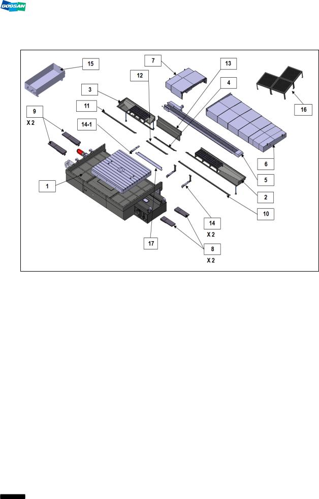
4.1Table Bed Ass’y
No. |
Item No. |
Definition |
Q’ty |
Packing |
Weight |
remark |
|
No. |
|||||||
|
|
|
|
|
|
||
1 |
160301-00136A |
TABLE BED ASSY |
1 |
1 |
17 Ton |
|
|
|
|
|
|
|
|
|
|
2 |
110961-00144D |
TRAY;(1) |
1 |
8 |
|
|
|
|
|
|
|
|
|||
110958-01660 |
SUPPORT,TRAY |
(1) |
|
|
|||
|
|
|
|
||||
|
|
|
|
|
|
|
|
3 |
110961-00145D |
TRAY;(2) |
1 |
8 |
|
|
|
|
|
|
|
|
|||
110958-01660 |
SUPPORT,TRAY |
(2) |
|
|
|||
|
|
|
|
||||
|
|
|
|
|
|
|
|
4 |
110961-00146C |
TRAY;(3) |
1 |
8 |
|
|
|
|
|
|
|
|
|
|
|
5 |
900115-00582A |
CONVEYOR,CHIP; |
1 |
8 |
|
|
|
|
|
|
|
|
|
|
|
6 |
110510-00428B |
COVER,SLIDE;(X4000)R |
1 |
1 |
|
|
|
|
|
|
|
|
|
|
|
7 |
110510-00427B |
COVER,SLIDE;(X4000)L |
1 |
1 |
|
|
|
|
|
|
|
|
|
|
|
8 |
|
BRACKET,SLIDE |
|
7 |
|
|
|
|
110423-03265A |
2 |
|
|
|
||
|
COVER;X-R |
|
|
|
|||
|
|
|
|
|
|
||
|
|
|
|
|
|
|
|
9 |
110423-03266A |
BRACKET,SLIDE |
2 |
7 |
|
|
|
|
COVER;X-L |
|
|
|
|||
|
|
|
|
|
|
||
|
|
|
|
|
|
|
|
10 |
110508-10529C |
COVER;TRAY,(1) |
1 |
8 |
|
|
|
|
|
|
|
|
|
|
|
11 |
110508-10530C |
COVER;TRAY,(2) |
1 |
8 |
|
|
|
|
|
|
|
|
|
|
16

DBC 130II |
|
|
|
|
DBC130II ISE41 |
|||
|
|
|
|
|
|
|
|
|
|
|
|
|
|
|
|
|
|
|
No. |
Item No. |
Definition |
Q’ty |
Packing |
Weight |
remark |
|
|
No. |
|||||||
|
|
|
|
|
|
|
|
|
|
12 |
110961-00183 |
COVER;CENTER |
1 |
8 |
|
|
|
|
|
|
|
|
|
|
|
|
|
13 |
110508-11089C |
COVER,REAR; |
1 |
8 |
|
|
|
|
|
|
|
|
|
|
|
|
|
14 |
110423-03095A |
BRACKET;TRAY |
2 |
8 |
|
|
|
|
|
|
|
|
|
|
||
110958-01647A |
SUPPORT;TRAY |
(2) |
|
|
|
|||
|
|
|
|
|
|
|||
|
|
|
|
|
|
|
|
|
|
14-1 |
110423-03095A |
BRACKET;TRAY |
1 |
8 |
|
|
|
|
|
|
|
|
|
|
|
|
|
15 |
230104-01477 |
BUCKET;OIL |
1 |
8 |
|
|
|
|
|
|
|
|
|
|
|
|
|
16 |
L56301092B |
STAND, FLOOR |
3 |
8 |
|
|
|
|
|
|
|
|
|
|
|
|
|
17 |
150119-00381 |
PAN; OIL |
1 |
8 |
|
|
|
|
|
|
|
|
|
|
|
|
17

DBC 130II |
DBC130II ISE41 |
|
|
4.2 Column Bed Ass’y
No. |
Item No. |
Definition |
Q’ty |
Packing |
Weight |
remark |
|
No. |
|||||||
|
|
|
|
|
|
||
1 |
160301-00144A |
COLUMN BED ASSY |
1 |
2 |
11Ton |
|
|
|
|
|
|
|
|
|
|
2 |
110510-00495 |
SLIDE COVER(FRONT) |
1 |
2 |
|
|
|
|
|
|
|
|
|
|
|
3 |
110961-00150 |
TRAY(R) |
1 |
8 |
|
|
|
|
|
|
|
|
|
|
|
4 |
110961-00153C |
TRAY(L) |
1 |
8 |
|
|
|
|
|
|
|
|
|
|
|
5 |
101556-00002B |
REMOVER,CHIP(R) |
1 |
8 |
|
|
|
|
|
|
|
|
|
|
|
6 |
101556-00348 |
REMOVER,CHIP(L) |
1 |
8 |
|
|
|
|
|
|
|
|
|
|
|
7 |
110510-00020A |
SLIDE COVER(REAR) |
1 |
2 |
|
|
|
|
|
|
|
|
|
|
|
8 |
250205-00868A |
BASE PLATE |
1 |
|
|
|
|
|
|
|
8 |
|
|
||
110423-03229A |
BRACKET,FRAME |
(1) |
|
|
|||
|
|
|
|
||||
|
|
|
|
|
|
|
|
9 |
110508-00986B |
BASE COVER(R) |
1 |
8 |
|
|
|
|
|
|
|
|
|
|
|
10 |
110508-10915C |
BASE COVER(L) |
1 |
8 |
|
|
|
|
|
|
|
|
|
|
|
11 |
110508-12561 |
COVER, CHIP(2) |
1 |
8 |
|
|
|
|
|
|
|
|
|
|
|
12 |
150119-00100 |
PAN, OIL(R) |
1 |
8 |
|
|
|
|
|
|
|
|
|
|
|
13 |
150119-00101 |
PAN, OIL(L) |
1 |
8 |
|
|
|
|
|
|
|
|
|
|
|
14 |
110423-03780 |
BRACKET; TRAY |
8 |
8 |
|
|
|
|
|
|
|
|
|
|
|
14-1 |
110423-03799 |
BRACKET; TRAY(2) |
1 |
8 |
|
|
|
|
|
|
|
|
|
|
|
15 |
B26280544B |
COVER; GUIDE RAIL (1) |
1 |
7 |
|
|
|
|
|
|
|
|
|
|
|
16 |
B26212163B |
BLOCK (U) |
1 |
8 |
|
|
|
|
|
|
|
|
|
|
18
DBC 130II |
|
|
|
|
DBC130II ISE41 |
|||
|
|
|
|
|
|
|
|
|
|
|
|
|
|
|
|
|
|
|
No. |
Item No. |
Definition |
Q’ty |
Packing |
Weight |
remark |
|
|
No. |
|||||||
|
|
|
|
|
|
|
|
|
|
17 |
111001-00063 |
PROTECTOR; CHIP |
1 |
8 |
|
|
|
|
|
|
|
|
|
|
|
|
|
18 |
110423-03590 |
BRACKE;PLATE,BASE |
4 |
8 |
|
|
|
|
|
|
|
|
|
|
|
|
|
19 |
B13210193A |
POSITION_BLOCK |
1 |
7 |
|
|
|
|
|
|
|
|
|
|
|
|
19

DBC 130II |
DBC130II ISE41 |
|
|
4.3 Column Body Ass’y
No. |
Item No. |
Definition |
Q’ty |
Packing |
Weight |
remark |
|
No. |
|||||||
|
|
|
|
|
|
||
1 |
190108-00149C |
COLUMN ASSY |
1 |
3 |
7Ton |
|
|
|
|
|
|
|
|
|
|
2 |
B26293123 |
MULTI COVER |
2 |
8 |
|
|
|
|
|
|
|
|
|
|
|
3 |
160609-02656 |
FRAME, TOP COVER |
1 |
8 |
|
|
|
|
|
|
|
|
|||
B26212173C |
BLOCK(T) |
(1) |
|
|
|||
|
|
|
|
||||
|
|
|
|
|
|
|
|
4 |
110508-10630 |
UPPER, COVER |
1 |
8 |
|
|
|
|
|
|
|
|
|
|
|
5 |
110508-01007B |
UPPER, COVER |
1 |
8 |
|
|
|
|
|
|
|
|
|
|
|
|
160609-02657 |
FRAME, SIDE COVER |
1 |
|
|
|
|
|
|
|
|
|
|
|
|
6 |
110517-00573B |
COVER, SIDE(R-U) |
(1) |
8 |
|
|
|
|
|
|
|
|
|
|
|
|
110517-00574B |
COVER, SIDE(R-B) |
(1) |
|
|
|
|
|
|
|
|
|
|
|
|
7 |
110508-10978A |
COVER, FRONT; MIDDLE |
1 |
8 |
|
|
|
|
|
|
|
|
|
|
|
8 |
110508-10625B |
COVER, FRONT(R-U) |
1 |
8 |
|
|
|
|
|
|
|
|
|
|
|
9 |
110508-10626C |
COVER, FRONT(R-B) |
1 |
8 |
|
|
|
|
|
|
|
|
|
|
|
10 |
110508-10622 |
COVER, FRONT(U) |
1 |
8 |
|
|
|
|
|
|
|
|
|
|
|
11 |
110508-10624B |
COVER, FRONT(B) |
1 |
8 |
|
|
|
|
|
|
|
|
|
|
|
12 |
110517-00571B |
COVER, SIDE(L-U) |
1 |
8 |
|
|
|
|
|
|
|
|
|
|
|
13 |
110517-00572B |
COVER, SIDE(L-B) |
1 |
8 |
|
|
|
|
|
|
|
|
|
|
|
14 |
110508-12560 |
COVER, CHIP(1) |
1 |
8 |
|
|
|
|
|
|
|
|
|
|
|
15 |
110508-03563 |
COVER, HOSE |
2 |
8 |
|
|
|
|
|
|
|
|
|
|
|
16 |
110958-02027 |
SUPPORT, CABLE CHAIN |
2 |
8 |
|
|
|
|
|
|
|
|
|
|
20

DBC 130II |
DBC130II ISE41 |
|
|
4.4 Spindle Head Ass’y |
|
|
|
|
|
|
|
DBC130II |
|
DBC250II |
|
|
|
|
|
|
No. |
Item No. |
Definition |
Q’ty |
Packi |
Weight |
remark |
||
DBC130II |
DBC250II |
ng No. |
||||||
|
|
|
|
|
||||
1 |
160401-00176B |
160401-00113 |
SPINDLE HEAD ASSY |
1 |
4 |
2.5Ton |
|
|
|
|
|
|
|
|
|
|
|
2 |
B26290123 |
B26290123 |
BLOCK,SCALE(Y) |
1 |
4 |
|
|
|
|
|
|
|
|
|
|
|
|
|
250205-01099 |
B25116023A |
PLATE,BACK(2) |
1 |
7 |
|
|
|
|
|
|
|
|
|
|
|
|
|
B14115073A |
B25116073B |
GIB,LOWER |
1 |
7 |
|
|
|
|
|
|
|
|
|
|
|
|
|
B14115063A |
B25116063B |
GIB,LOWER |
1 |
7 |
|
|
|
|
|
|
|
|
|
|
|
|
|
250205-01098 |
B25116013A |
PLATE,BACK(1) |
1 |
7 |
|
|
|
|
|
|
|
|
|
|
|
|
|
B14115083A |
B25116083B |
GIB,UPPER |
1 |
7 |
|
|
|
|
|
|
|
|
|
|
|
|
|
B14115053A |
B25116053B |
GIB,UPPER |
1 |
7 |
|
|
|
|
|
|
|
|
|
|
|
|
3 |
250205-01099 |
B25116023A |
PLATE,BACK(2) |
1 |
7 |
|
|
|
|
|
|
|
|
|
|
||
B14115083A |
B25116083B |
GIB,UPPER |
1 |
7 |
|
|
||
|
|
|
||||||
|
|
|
|
|
|
|
|
|
|
B14115053A |
B25116053B |
GIB,UPPER |
1 |
7 |
|
|
|
|
|
|
|
|
|
|
|
|
|
250205-01098 |
B25116013A |
PLATE,BACK(1) |
1 |
7 |
|
|
|
|
|
|
|
|
|
|
|
|
|
B14115073A |
B25116073B |
GIB,LOWER |
1 |
7 |
|
|
|
|
|
|
|
|
|
|
|
|
|
B14115063A |
B25116063B |
GIB,LOWER |
1 |
7 |
|
|
|
|
|
|
|
|
|
|
|
|
|
B25116033B |
B25116033B |
PLATE(1),REFERENCE |
1 |
7 |
|
|
|
|
|
|
|
|
|
|
|
|
|
B25116043B |
B25116043B |
PLATE(2),REFERENCE |
1 |
7 |
|
|
|
|
|
|
|
|
|
|
|
|
21

DBC 130II |
DBC130II ISE41 |
|
|
4.5 Duct Ass’y
No. |
Item No. |
Definition |
Q’ty |
Packing |
Weight |
remark |
|
No. |
|||||||
|
|
|
|
|
|
||
1 |
|
NC, OP BOX |
1 |
6 |
|
|
|
|
|
|
|
|
|
|
|
|
B14210193H |
PUMP,LUBRICATION |
1 |
|
|
|
|
|
|
|
|
|
|
|
|
2 |
400206-00202 |
COOLER, OIL |
(1) |
6 |
|
|
|
|
|
|
|
|
|
|
|
|
160609-02649B |
FRAME,COOLER |
(1) |
|
|
|
|
|
|
|
|
|
|
|
|
3 |
460103-00534A |
DUCT;(2) |
1 |
8 |
|
|
|
|
|
|
|
|
|
|
|
4 |
110505-00276A |
COVER,DUCT;(2) |
1 |
8 |
|
|
|
|
|
|
|
|
|
|
|
5 |
110505-00274A |
COVER, FRAME DUCT |
1 |
8 |
|
|
|
|
|
|
|
|
|
|
|
6 |
460103-00533A |
DUCT;(1) |
1 |
8 |
|
|
|
|
|
|
|
|
|
|
|
7 |
110505-00275A |
COVER,DUCT;(1) |
1 |
8 |
|
|
|
|
|
|
|
|
|
|
|
|
130301-00254A |
CHAIN,CABLE;Z2000 |
1 |
|
|
|
|
|
|
|
|
|
|
|
|
8 |
110958-01897 |
SUPPORT;CABLE CHAIN |
(1) |
6 |
|
|
|
|
|
|
|
|
|
|
|
|
110958-01903 |
SUPPORT;FRAME |
(1) |
|
|
|
|
|
|
|
|
|
|
|
|
9 |
110516-00089 |
COVER,SUPPORT(4) |
1 |
8 |
|
|
|
|
|
|
|
|
|
|
|
10 |
110516-00088 |
COVER,SUPPORT(3) |
1 |
8 |
|
|
|
|
|
|
|
|
|
|
|
11 |
110516-00087 |
COVER(1) |
1 |
8 |
|
|
|
|
|
|
|
|
|
|
|
12 |
110516-00086 |
COVER(2) |
1 |
8 |
|
|
|
|
|
|
|
|
|
|
|
13 |
460103-00656 |
DUCT(3) |
1 |
2 |
|
|
|
|
|
|
|
|
|
|
|
14 |
460103-00536B |
DUCT(4) |
1 |
2 |
|
|
|
|
|
|
|
|
|||
460103-00537B |
DUCT(5) |
(1) |
|
|
|||
|
|
|
|
||||
|
|
|
|
|
|
|
22
DBC 130II |
|
|
|
|
DBC130II ISE41 |
|
||
|
|
|
|
|
|
|
|
|
|
|
|
|
|
|
|
|
|
|
|
B26419323B |
SUPPORT;DUCT |
(4) |
|
|
|
|
|
|
|
|
|
|
|
|
|
|
15 |
110505-00321 |
COVER;DUCT(3) |
1 |
8 |
|
|
|
|
|
|
|
|
|
|
|
|
|
16 |
110505-00277B |
COVER;DUCT(4) |
1 |
8 |
|
|
|
|
|
|
|
|
|
|
|
|
|
17 |
110505-00278A |
COVER;DUCT(5) |
1 |
8 |
|
|
|
|
|
|
|
|
|
|
|
|
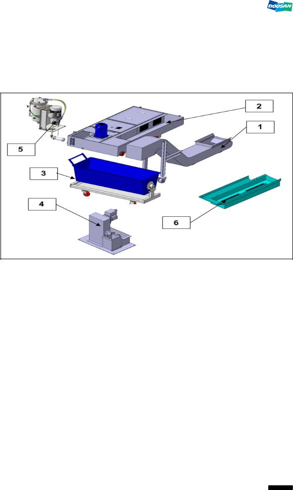
4.6 Coolant Tank, Chip Bucket, Chip Conveyor, TSC Ass’y, T/F(Option)
No. |
Item No. |
Definition |
Q’ty |
Packing |
Weight |
remark |
|
No. |
|||||||
|
|
|
|
|
|
||
1 |
B26575011 |
LIFT UP CHIP CONV |
1 |
7 |
|
|
|
|
MAIN BODY |
|
|
||||
|
|
|
|
|
|
||
|
|
|
|
|
|
|
|
2 |
450102-00131A |
COOLANT TANK MAIN |
1 |
7 |
|
|
|
|
BODY |
|
|
||||
|
|
|
|
|
|
||
|
|
|
|
|
|
|
|
3 |
C51221011E |
CHIP BUCKET |
1 |
7 |
|
|
|
|
|
|
|
|
|
|
|
4 |
R76595 |
OIL SKIMMER (OPT.) |
1 |
7 |
|
|
|
|
|
|
|
|
|
|
|
5 |
R37278 |
TSC PUMP (OPT.) |
1 |
7 |
|
|
|
|
|
|
|
|
|
|
|
6 |
101558-00168 |
CHIP PAN (W/O CHIP |
1 |
7 |
|
|
|
CONV.) |
|
|
|||||
|
|
|
|
|
|
||
|
|
|
|
|
|
|
23

DBC 130II |
DBC130II ISE41 |
|
|
4.7 Tool Magazine Ass’y (Option)
No. |
Item No. |
Definition |
Q’ty |
Packing |
Weight |
remark |
|
No. |
|||||||
|
|
|
|
|
|
||
1 |
100702-00154 |
40TOOLS MAGAZINE |
1 |
5 |
2.4Ton |
|
|
|
|
|
|
|
|
|
|
|
100702-00172 |
60, 90 TOOLS |
1 |
5 |
4.5Ton |
|
|
|
MAGAZINE |
|
|||||
|
|
|
|
|
|
||
|
|
|
|
|
|
|
|
2 |
860103-00533A |
FIXTURE;MAGAZINE |
1 |
2 |
|
|
|
|
|
|
|
|
|
|
|
|
860103-00637 |
FIXTURE;MAGAZINE |
1 |
2 |
|
|
|
|
|
|
|
|
|
|
|
3 |
160101-00277C |
TOOL MAGAZINE BASE |
1 |
5 |
|
|
|
|
|
|
|
|
|
|
24

DBC 130II |
DBC130II ISE41 |
|
|
|
|
|
|
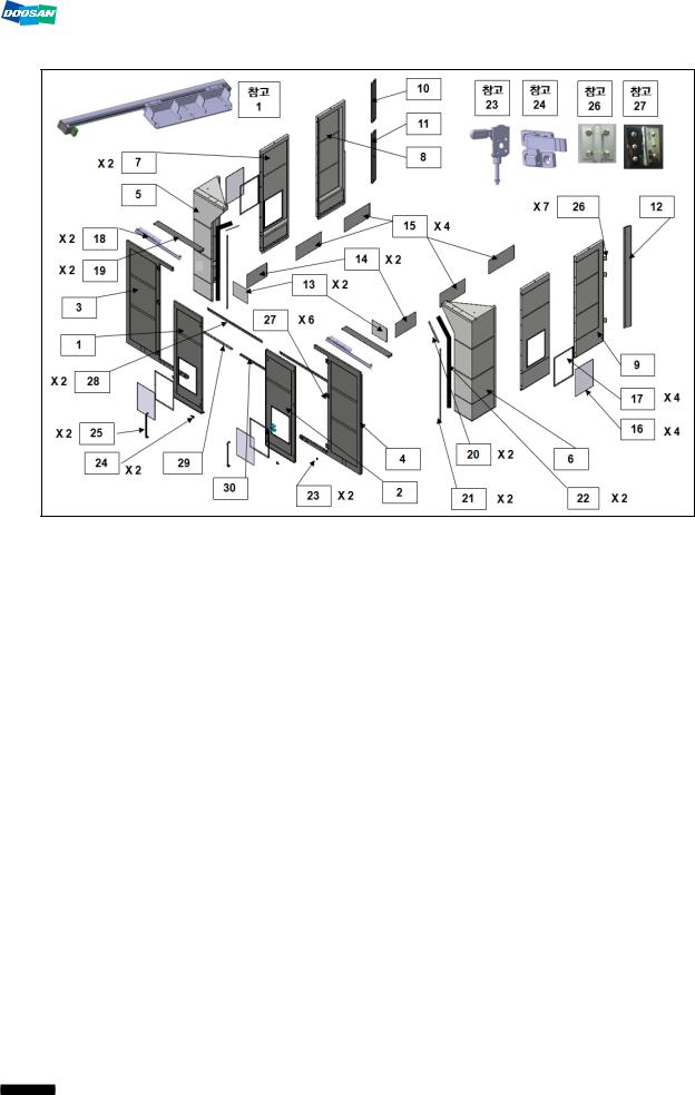
4.8 Semi Splash Guard – Operator Part (Option) |
|
|
|
|
|
|
|
|
|
|
|
No. |
Item No. |
Definition |
Q’ty |
Packing |
Weight |
remark |
|
No. |
|||||||
|
|
|
|
|
|
||
1 |
110508-11061A |
COVER, TOP |
1 |
8 |
|
|
|
|
|
|
|
|
|
|
|
2 |
110302-00536A |
BAR, SAFETY |
1 |
8 |
|
|
|
|
|
|
|
|
|
|
|
3 |
110955-00203A |
STEP, OPERATOR |
1 |
8 |
|
|
|
|
|
|
|
|
|
|
|
4 |
102302-00148B |
FENCE, OPERATOR(4) |
1 |
8 |
|
|
|
|
|
|
|
|
|
|
|
5 |
102302-00149B |
FENCE, OPERATOR(5) |
1 |
8 |
|
|
|
|
|
|
|
|
|
|
|
6 |
102302-00145B |
FENCE, OPERATOR(1) |
1 |
8 |
|
|
|
|
|
|
|
|
|
|
|
7 |
102302-00171A |
FENCE, OPERATOR(2) |
1 |
8 |
|
|
|
|
|
|
|
|
|
|
|
8 |
102302-00144A |
FENCE, |
1 |
8 |
|
|
|
ROTATING,OPERATOR |
|
|
|||||
|
|
|
|
|
|
||
|
|
|
|
|
|
|
|
9 |
910801-00029A |
ROOF, OP DOOR(2) |
1 |
8 |
|
|
|
|
|
|
|
|
|
|
|
10 |
910801-00030A |
ROOF, OP DOOR(3) |
1 |
8 |
|
|
|
|
|
|
|
|
|
|
|
11 |
910801-00034 |
ROOF, OP DOOR(1) |
1 |
8 |
|
|
|
|
|
|
|
|
|
|
|
12 |
R70180 |
HANDLE |
2 |
7 |
|
|
|
|
|
|
|
|
|
|
|
13 |
LAMP |
|
1 |
6 |
|
|
|
|
|
|
|
|
|
|
|
14 |
110922-00564 |
GUIDE,DOOR;(2) |
1 |
8 |
|
|
|
|
|
|
|
|
|
|
|
15 |
110922-00563 |
GUIDE,DOOR;(1) |
1 |
8 |
|
|
|
|
|
|
|
|
|
|
|
16 |
110508-11065 |
COVER;(4),FENCE,OPER |
1 |
8 |
|
|
|
ATOR |
|
|
|||||
|
|
|
|
|
|
||
|
|
|
|
|
|
|
|
17 |
110508-11062 |
COVER;(1),FENCE,OPER |
1 |
8 |
|
|
|
|
|
|
|
|
|
|
25

|
DBC 130II |
|
|
|
DBC130II ISE41 |
||
|
|
|
|
|
|
|
|
|
|
|
|
|
|
|
|
|
No. |
Item No. |
Definition |
Q’ty |
Packing |
Weight |
remark |
|
No. |
||||||
|
|
|
|
|
|
|
|
|
|
|
ATOR |
|
|
|
|
|
|
|
|
|
|
|
|
|
18 |
110508-12695 |
COVER;(2),FENCE,OPER |
1 |
8 |
|
|
|
ATOR |
|
|
||||
|
|
|
|
|
|
|
|
|
|
|
|
|
|
|
|
|
19 |
110508-11064 |
COVER;(3),FENCE,OPER |
1 |
8 |
|
|
|
ATOR |
|
|
||||
|
|
|
|
|
|
|
|
|
|
|
|
|
|
|
|
|
20 |
110508-12502 |
COVER,OPERATOR |
1 |
8 |
|
|
|
FENCE(5) |
|
|
||||
|
|
|
|
|
|
|
|
|
|
|
|
|
|
|
|
|
21 |
110508-12505 |
COVER,OPERATOR |
1 |
8 |
|
|
|
FENCE(1) |
|
|
||||
|
|
|
|
|
|
|
|
|
|
|
|
|
|
|
|
|
22 |
B31722324 |
STOPPER, DOOR |
4 |
7 |
|
|
|
|
|
|
|
|
||
|
B31722314 |
BRACKET, STOPPER |
(4) |
|
|
||
|
|
|
|
|
|||
|
23 |
102301-00099B |
DOOR, OPERATOR(2) |
1 |
8 |
|
|
|
|
|
|
|
|
|
|
|
24 |
102301-00098A |
DOOR, OPERATOR(1) |
1 |
8 |
|
|
|
|
|
|
|
|
|
|
|
25 |
B13722023 |
PLATE |
2 |
8 |
|
|
|
|
|
|
|
|
|
|
|
26 |
B13721313B |
GLASS(1), SAFETY |
2 |
8 |
|
|
|
|
|
|
|
|
|
|
|
27 |
R70177 |
HINGE;SPRING |
4 |
8 |
|
|
|
|
|
|
|
|
|
|
|
28 |
ESWSF0013 |
SAFETY SWITCH |
2 |
6 |
|
|
|
|
|
|
|
|
||
|
110423-02251A |
PLATE,SWITCH |
(2) |
|
|
||
|
|
|
|
|
|||
|
|
R87057A |
KEY;SWITCH |
2 |
|
|
|
|
|
|
|
|
|
|
|
|
|
110423-03897 |
BRACKET,SAFETY |
(2) |
|
|
|
|
29 |
SWITCH(3) |
7 |
|
|
||
|
|
|
|
|
|||
|
|
110423-03896 |
BRACKET,SAFETY |
(2) |
|
|
|
|
|
SWITCH(2) |
|
|
|
||
|
|
|
|
|
|
|
|
|
30 |
110958-01928A |
SUPPORT;OPERATOR |
1 |
10 |
|
|
|
FENCE |
|
|
||||
|
|
|
|
|
|
|
|
|
|
|
|
|
|
|
|
26

DBC 130II |
DBC130II ISE41 |
|
|
|
|
|
|
4.9 Semi Splash Guard – Magazine Part (Option) |
|
|
|
|
|
|
|
No. |
Item No. |
Definition |
Q’ty |
Packing |
Weight |
remark |
|
No. |
|||||||
|
|
|
|
|
|
||
1 |
910801-00035C |
ROOF, ATC FENCE |
1 |
8 |
|
|
|
|
|
|
|
|
|
|
|
2 |
102302-00155B |
FENCE, ATC(4) |
1 |
8 |
|
|
|
|
|
|
|
|
|
|
|
3 |
110508-12493A |
COVER, TOP |
1 |
8 |
|
|
|
|
|
|
|
|
|
|
|
4 |
110958-02118 |
SUPPORT |
1 |
8 |
|
|
|
|
|
|
|
|
|
|
|
5 |
102302-00154A |
FENCE, ATC(3) |
1 |
8 |
|
|
|
|
|
|
|
|
|
|
|
6 |
110508-10979A |
COVER;ATC FENCE |
1 |
8 |
|
|
|
|
|
|
|
|
|
|
|
7 |
160629-00005 |
FOOT,LEVELING |
1 SET |
8 |
|
|
|
|
|
|
|
|
|
|
|
8 |
102302-00172 |
FENCE, ATC(1) |
1 |
8 |
|
|
|
|
|
|
|
|
|
|
|
9 |
102302-00151A |
FENCE, ROTATING |
1 |
8 |
|
|
|
|
|
|
|
|
|
|
|
10 |
102302-00169 |
FENCE, ROTATING |
1 |
8 |
|
|
|
|
|
|
|
|
|
|
|
11 |
500119-00154 |
GLASS, SAFETY |
1 |
8 |
|
|
|
|
|
|
|
|
|
|
|
12 |
250205-00096 |
PLATE, GLASS |
1 |
8 |
|
|
|
|
|
|
|
|
|
|
|
13 |
110423-03695 |
BRACKET |
1 |
8 |
|
|
|
|
|
|
|
|
|
|
|
14 |
R70177 |
HINGE, SPRING |
7 |
8 |
|
|
|
|
|
|
|
|
|
|
|
15 |
110958-01929A |
SUPPORT;ATC FENCE |
1 |
10 |
|
|
|
|
|
|
|
|
|
|
27
DBC 130II |
DBC130II ISE41 |
|
|
4.10 Semi Splash Guard – Table Part (Option)
No. |
Item No. |
Definition |
Q’ty |
Packing |
Weight |
remark |
|
No. |
|||||||
|
|
|
|
|
|
||
1 |
102301-00506B |
DOOR;RATATING(R), TABLE |
1 |
8 |
|
|
|
|
|
|
|
|
|
|
|
2 |
102301-00507A |
DOOR;RATATING(L), TABLE |
1 |
8 |
|
|
|
|
|
|
|
|
|
|
|
3 |
102301-00504A |
DOOR;SLIDING(R),TABLE |
1 |
8 |
|
|
|
|
|
|
|
|
|
|
|
4 |
102301-00505A |
DOOR;SLIDING(L),TABLE |
1 |
8 |
|
|
|
|
|
|
|
|
|
|
|
5 |
102302-00207 |
FENCE;TABLE(2) |
1 |
8 |
|
|
|
|
|
|
|
|
|
|
|
6 |
102302-00206 |
FENCE;TABLE(1) |
1 |
8 |
|
|
|
|
|
|
|
|
|
|
|
7 |
102302-00208 |
FENCE;TABLE(3) |
2 |
8 |
|
|
|
|
|
|
|
|
|
|
|
8 |
102302-00209 |
FENCE;TABLE(4) |
1 |
8 |
|
|
|
|
|
|
|
|
|
|
|
9 |
102302-00210 |
FENCE;TABLE(5) |
1 |
8 |
|
|
|
|
|
|
|
|
|
|
|
10 |
102302-00167 |
FENCE;ROTATING,SEMI TABLE |
1 |
8 |
|
|
|
|
|
|
|
|
|
|
|
11 |
102302-00168 |
FENCE;ROTATING,SEMI TABLE |
1 |
8 |
|
|
|
|
|
|
|
|
|
|
|
12 |
102302-00166 |
FENCE;ROTATING,SEMI TABLE |
1 |
8 |
|
|
|
|
|
|
|
|
|
|
|
13 |
110508-12426 |
COVER;FENCE,TABLE |
2 |
8 |
|
|
|
|
|
|
|
|
|
|
|
14 |
110508-12427A |
COVER;FENCE,TABLE |
2 |
8 |
|
|
|
|
|
|
|
|
|
|
|
15 |
110508-12428A |
COVER;FENCE,TABLE |
4 |
8 |
|
|
|
|
|
|
|
|
|
|
|
16 |
B13721313B |
GLASS(1); SAFETY |
4 |
8 |
|
|
|
|
|
|
|
|
|
|
|
17 |
B13721413B |
PLATE |
4 |
8 |
|
|
|
|
|
|
|
|
|
|
28
 Loading...