

D-link DGS-1510-10L, DGS-1510-28L, DGS-1510-28XMP, DGS-1510-28X, DGS-1510-28XS User Manual [ru]
...

DGS-1510/ME Series Metro Ethernet Switch Web UI Reference Guide
Information in this document is subject to change without notice.
© 2015 D-Link Corporation. All rights reserved.
Reproduction of this document in any manner whatsoever without the written permission of D-Link Corporation is strictly forbidden.
Trademarks used in this text: D-Link and the D-LINK logo are trademarks of D-Link Corporation; Microsoft and Windows are registered trademarks
of Microsoft Corporation.
Other trademarks and trade names may be used in this document to refer to either the entities claiming the marks and names or their products. D-
Link Corporation disclaims any proprietary interest in trademarks and trade names other than its own.
July 2015 P/N 651GS15ME015G
i

DGS-1510/ME Series Metro Ethernet Switch Web UI Reference Guide
Table of Contents
Intended Readers ........................................................................................................................................................... 1
Typographical Conventions ............................................................................................................................................ 1
Notes, Notices and Cautions .......................................................................................................................................... 1
Safety Instructions .......................................................................................................................................................... 2
Safety Cautions ........................................................................................................................................................... 2
General Precautions for Rack-Mountable P roducts ....................................................................................................... 2
Protecting Against Electrostatic Discharg e .................................................................................................................... 3
Chapter 1 Web-based Switch Configuration ........................................................................... 5
Introduction ..................................................................................................................................................................... 5
Login to the Web Manager ............................................................................................................................................. 5
Web-based User Interface .............................................................................................................................................. 6
Areas of the User Interface ......................................................................................................................................... 6
Web Pages ..................................................................................................................................................................... 7
Chapter 2 System Configuration .............................................................................................. 8
Device Information .......................................................................................................................................................... 8
System Information Settings ........................................................................................................................................... 8
Port Configuration ........................................................................................................................................................... 9
DDM ............................................................................................................................................................................ 9
Port Settings ............................................................................................................................................................. 16
Port Description Settings .......................................................................................................................................... 18
Port Error Disabled ................................................................................................................................................... 18
Jumbo Frame Settings .............................................................................................................................................. 19
EEE Settings ............................................................................................................................................................. 19
PoE ............................................................................................................................................................................... 20
PoE System Settings ................................................................................................................................................ 21
PoE Port Settings ...................................................................................................................................................... 22
Serial Port Settings ....................................................................................................................................................... 24
Warning Temperature Settings .................................................................................................................................... 24
System Log Configuration ............................................................................................................................................ 25
System Log Settings ................................................................................................................................................. 25
System Log Server Settings ..................................................................................................................................... 26
System Log ............................................................................................................................................................... 26
System Log & Trap Settings ..................................................................................................................................... 27
System Severity Settings .......................................................................................................................................... 27
Time Range Settings .................................................................................................................................................... 28
Time Settings ................................................................................................................................................................ 29
User Accounts Settings ................................................................................................................................................ 29
Command Logging Settings ......................................................................................................................................... 30
Chapter 3 Management ........................................................................................................... 31
ARP .............................................................................................................................................................................. 31
Static ARP Settings ................................................................................................................................................... 31
ARP Table ................................................................................................................................................................. 31
Gratuitous ARP ............................................................................................................................................................. 32
Gratuitous ARP Global Settings ............................................................................................................................... 32
Gratuitous ARP Settings ........................................................................................................................................... 33
IPv6 Neighbor Settings ................................................................................................................................................. 33
IP Interface ................................................................................................................................................................... 34
System IP Address Settings ..................................................................................................................................... 34
ii

DGS-1510/ME Series Metro Ethernet Switch Web UI Reference Guide
Interface Settings ...................................................................................................................................................... 36
Management Settings ................................................................................................................................................... 38
Session Table ............................................................................................................................................................... 39
Single IP Management ................................................................................................................................................. 39
Single IP Settings ...................................................................................................................................................... 41
Topology ................................................................................................................................................................... 42
Firmware Upgrade .................................................................................................................................................... 48
Configuration File Backup/Restore ........................................................................................................................... 48
Upload Log File ......................................................................................................................................................... 49
SNMP Settings ............................................................................................................................................................. 49
SNMP Global Settings .............................................................................................................................................. 50
SNMP Traps Settings ............................................................................................................................................... 51
SNMP Linkchange Traps Settings ............................................................................................................................ 51
SNMP View Table Settings ....................................................................................................................................... 52
SNMP Community Table Settings ............................................................................................................................ 53
SNMP Group Table Settings..................................................................................................................................... 54
SNMP Engine ID Settings ......................................................................................................................................... 54
SNMP User Table Settings ....................................................................................................................................... 55
SNMP Host Table Settings ....................................................................................................................................... 56
RMON Settings ......................................................................................................................................................... 56
Telnet Settings .............................................................................................................................................................. 57
Web Settings ................................................................................................................................................................ 57
Chapter 4 L2 Features ............................................................................................................. 59
VLAN ............................................................................................................................................................................ 59
802.1Q VLAN Settings .............................................................................................................................................. 64
802.1v Protocol VLAN ............................................................................................................................................... 67
GVRP ........................................................................................................................................................................ 69
MAC-based VLAN Settings ....................................................................................................................................... 71
PVID Auto Assign Settings ....................................................................................................................................... 71
VLAN Trunk Settings ................................................................................................................................................ 71
Browse VLAN ............................................................................................................................................................ 72
Show VLAN Ports ..................................................................................................................................................... 73
QinQ ............................................................................................................................................................................. 73
QinQ Settings ............................................................................................................................................................ 75
VLAN Translation Settings ........................................................................................................................................ 75
Layer 2 Protocol Tunneling Settings ............................................................................................................................ 76
Spanning Tree .............................................................................................................................................................. 77
STP Bridge Global Settings ...................................................................................................................................... 79
STP Port Settings ..................................................................................................................................................... 80
MST Configuration Identification ............................................................................................................................... 81
STP Instance Settings .............................................................................................................................................. 82
MSTP Port Information ............................................................................................................................................. 82
Link Aggregation ........................................................................................................................................................... 83
Port Trunking Settings .............................................................................................................................................. 85
LACP Port Settings ................................................................................................................................................... 86
FDB ............................................................................................................................................................................... 87
Static FDB Settings ................................................................................................................................................... 87
MAC Notification Settings ......................................................................................................................................... 88
MAC Address Aging Time Settings .......................................................................................................................... 89
MAC Address Table .................................................................................................................................................. 89
ARP & FDB Table ..................................................................................................................................................... 90
iii

DGS-1510/ME Series Metro Ethernet Switch Web UI Reference Guide
L2 Multicast Control ...................................................................................................................................................... 91
IGMP Snooping ......................................................................................................................................................... 91
MLD Snooping .......................................................................................................................................................... 99
Multicast VLAN ....................................................................................................................................................... 107
Multicast Filtering ........................................................................................................................................................ 110
IPv4 Multicast Filtering ............................................................................................................................................ 110
IPv6 Multicast Filtering ............................................................................................................................................ 112
Multicast Filtering Mode .......................................................................................................................................... 114
ERPS Settings ............................................................................................................................................................ 115
LLDP ........................................................................................................................................................................... 117
LLDP ....................................................................................................................................................................... 118
LLDP-MED .............................................................................................................................................................. 126
NLB FDB Settings ...................................................................................................................................................... 128
Chapter 5 L3 Features ........................................................................................................... 130
IPv4 Static/Default Route Settings ............................................................................................................................. 130
IPv4 Route Table ........................................................................................................................................................ 130
IPv6 Static/Default Route Settings ............................................................................................................................. 131
Chapter 6 QoS ........................................................................................................................ 132
802.1p Settings ........................................................................................................................................................... 133
802.1p Default Priority Settings .............................................................................................................................. 133
802.1p User Priority Settings .................................................................................................................................. 134
802.1p Map Settings ............................................................................................................................................... 135
Bandwidth Control ...................................................................................................................................................... 135
Bandwidth Control Settings ..................................................................................................................................... 135
Queue Bandwidth Control Settings ......................................................................................................................... 136
Traffic Control Settings ............................................................................................................................................... 137
DSCP .......................................................................................................................................................................... 140
DSCP Trust Settings ............................................................................................................................................... 140
DSCP Map Settings ................................................................................................................................................ 140
HOL Blocking Prevention ........................................................................................................................................... 142
Scheduling Settings .................................................................................................................................................... 143
QoS Scheduling ...................................................................................................................................................... 143
QoS Scheduling Mechanism................................................................................................................................... 144
Chapter 7 ACL ........................................................................................................................ 146
ACL Configuration Wizard .......................................................................................................................................... 146
Access Profile List ...................................................................................................................................................... 147
Add an Ethernet ACL Profile ................................................................................................................................... 148
Adding an IPv4 ACL Profile .................................................................................................................................... 151
Adding an IPv6 ACL Profile .................................................................................................................................... 156
Adding a Packet Content ACL Profile ..................................................................................................................... 161
CPU Access Profile List .............................................................................................................................................. 164
Adding a CPU Ethernet ACL Profile ....................................................................................................................... 165
Adding a CPU IPv4 ACL Profile .............................................................................................................................. 168
Adding a CPU IPv6 ACL Profile .............................................................................................................................. 172
Adding a CPU Packet Content ACL Profile ............................................................................................................ 175
ACL Finder.................................................................................................................................................................. 178
ACL Flow Meter .......................................................................................................................................................... 179
Chapter 8 Security ................................................................................................................. 182
802.1X ........................................................................................................................................................................ 182
802.1X Global Settings ........................................................................................................................................... 187
802.1X Port Settings ............................................................................................................................................... 188
iv

DGS-1510/ME Series Metro Ethernet Switch Web UI Reference Guide
802.1X User Settings .............................................................................................................................................. 190
Guest VLAN Settings .............................................................................................................................................. 191
Authenticator State ................................................................................................................................................. 192
Authenticator Statistics ........................................................................................................................................... 192
Authenticator Session Statistics ............................................................................................................................. 193
Authenticator Diagnostics ....................................................................................................................................... 194
Initialize Port(s) ....................................................................................................................................................... 195
Reauthenticate Port(s) ............................................................................................................................................ 196
RADIUS ...................................................................................................................................................................... 197
Authentication RADIUS Server Settings ................................................................................................................. 197
RADIUS Accounting Settings.................................................................................................................................. 197
RADIUS Authentication ........................................................................................................................................... 198
RADIUS Account Client .......................................................................................................................................... 200
IP-MAC-Port Binding (IMPB) ...................................................................................................................................... 202
IMPB Global Settings .............................................................................................................................................. 202
IMPB Port Settings .................................................................................................................................................. 203
IMPB Entry Settings ................................................................................................................................................ 204
MAC Block List ........................................................................................................................................................ 204
DHCP Snooping ...................................................................................................................................................... 205
MAC-based Access Control (MAC) ............................................................................................................................ 206
MAC-based Access Control Settings ...................................................................................................................... 206
MAC-based Access Control Local Settings ............................................................................................................ 208
MAC-based Access Control Authentication Stat e .................................................................................................. 209
Compound Authentication .......................................................................................................................................... 209
Compound Authentication Settings ........................................................................................................................ 210
Port Security ............................................................................................................................................................... 210
Port Security Settings ............................................................................................................................................. 210
Port Security VLAN Settings ................................................................................................................................... 212
Port Security Entries ............................................................................................................................................... 213
ARP Spoofing Prevention Settings ............................................................................................................................. 213
BPDU Attack Protection ............................................................................................................................................. 214
Loopback Detection Settings ...................................................................................................................................... 215
Traffic Segmentation Settings .................................................................................................................................... 216
NetBIOS Filtering Settings .......................................................................................................................................... 217
DHCP Server Screening ............................................................................................................................................. 218
DHCP Server Screening Port Settings ................................................................................................................... 218
DHCP Offer Permit Entry Settings .......................................................................................................................... 219
Access Authentication Control.................................................................................................................................... 220
Enable Admin .......................................................................................................................................................... 221
Authentication Policy Settings ................................................................................................................................ 221
Application Authentication Settings ........................................................................................................................ 222
Authentication Server Group Settings .................................................................................................................... 223
Authentication Server Settings ............................................................................................................................... 224
Login Method Lists Settings .................................................................................................................................... 225
Enable Method Lists Settings ................................................................................................................................. 226
Local Enable Password Settings ............................................................................................................................ 227
SSL Settings ............................................................................................................................................................... 228
SSH ............................................................................................................................................................................ 230
SSH Settings ........................................................................................................................................................... 230
SSH Authentication Method and Algorithm Settings .............................................................................................. 231
SSH User Authentication List.................................................................................................................................. 233
v

DGS-1510/ME Series Metro Ethernet Switch Web UI Reference Guide
Trusted Host Settings ................................................................................................................................................. 233
Safeguard Engine Settings ......................................................................................................................................... 234
DoS Attack Prevention Settings ................................................................................................................................. 236
IGMP Access Control Settings ................................................................................................................................... 237
Chapter 9 Network Application ............................................................................................ 239
DHCP .......................................................................................................................................................................... 239
DHCP Relay ............................................................................................................................................................ 239
DHCP Local Relay Settings .................................................................................................................................... 245
DHCP Local Relay Option 82 Settings ................................................................................................................... 245
PPPoE Circuit ID Insertion Settings ........................................................................................................................... 246
SMTP Settings ............................................................................................................................................................ 247
SNTP .......................................................................................................................................................................... 248
SNTP Settings ........................................................................................................................................................ 248
Time Zone Settings ................................................................................................................................................. 249
Flash File System Settings ......................................................................................................................................... 251
Chapter 10 OAM ....................................................................................................................... 253
CFM ............................................................................................................................................................................ 253
CFM Settings .......................................................................................................................................................... 253
CFM Port Settings ................................................................................................................................................... 257
CFM MIPCCM Table ............................................................................................................................................... 258
CFM Loopback Settings .......................................................................................................................................... 258
CFM Linktrace Settings ........................................................................................................................................... 259
CFM Packet Counter .............................................................................................................................................. 260
CFM Fault Table ..................................................................................................................................................... 261
CFM MP Table ........................................................................................................................................................ 262
Ethernet OAM ............................................................................................................................................................. 262
Ethernet OAM Settings ........................................................................................................................................... 262
Ethernet OAM Configuration Settings ..................................................................................................................... 263
Ethernet OAM Event Log ........................................................................................................................................ 264
Ethernet OAM Statistics .......................................................................................................................................... 265
DULD Settings ............................................................................................................................................................ 266
Cable Diagnostics ....................................................................................................................................................... 267
Chapter 11 Monitoring ............................................................................................................ 269
Utilization .................................................................................................................................................................... 269
CPU Utilization ........................................................................................................................................................ 269
DRAM & Flash Utilization ........................................................................................................................................ 269
Port Utilization ......................................................................................................................................................... 270
Statistics ..................................................................................................................................................................... 270
Port Statistics .......................................................................................................................................................... 271
Packet Size ............................................................................................................................................................. 278
Mirror .......................................................................................................................................................................... 280
Port Mirror Settings ................................................................................................................................................. 280
Ping Test ..................................................................................................................................................................... 281
Trace Route ................................................................................................................................................................ 282
Peripheral ................................................................................................................................................................... 283
Device Environment ................................................................................................................................................ 283
Chapter 12 Save and Tools ..................................................................................................... 284
Save Configuration / Log ............................................................................................................................................ 284
Download firmware ..................................................................................................................................................... 284
Download Firmware From TFTP ............................................................................................................................ 284
Download Firmware From FTP ............................................................................................................................... 285
vi

DGS-1510/ME Series Metro Ethernet Switch Web UI Reference Guide
Download Firmware From HTTP ............................................................................................................................ 286
Upload Firmware ........................................................................................................................................................ 286
Upload Firmware To TFTP ..................................................................................................................................... 286
Upload Firmware To FTP ........................................................................................................................................ 286
Download Configuration ............................................................................................................................................. 287
Download Configuration From TFTP ...................................................................................................................... 287
Download Configuration From FTP ........................................................................................................................ 288
Download Configuration From HTTP ...................................................................................................................... 288
Upload Configuration .................................................................................................................................................. 289
Upload Configuration To TFTP ............................................................................................................................... 289
Upload Configuration To FTP ................................................................................................................................. 289
Upload Configuration To HTTP .............................................................................................................................. 290
Upload Log File .......................................................................................................................................................... 290
Upload Log To TFTP .............................................................................................................................................. 290
Upload Log To FTP ................................................................................................................................................. 291
Upload Log To HTTP .............................................................................................................................................. 291
Reset .......................................................................................................................................................................... 292
Reboot System ........................................................................................................................................................... 292
Appendix A Password Recovery Procedure .......................................................................... 294
Appendix B System Log Entries .............................................................................................. 295
Appendix C Trap Log Entries........................................................... Error! Bookmark not defined.
Appendix D RADIUS Attributes Assignment .................................. Error! Bookmark not defined.
Appendix E IETF RADIUS Attributes Support ................................ Err or ! Bookmark not defined.
vii

DGS-1510/ME Series Metro Ethernet Switch Web UI Reference Guide
Typewriter Font
Intended Readers
Intended Readers
Typographical Conventions
Notes, Notices and Cautions
Safety Instructions
General Precautions for Rack-Mountable Products
Protecting Against Electrostatic Discharge
The <Product Code> Series Web UI Reference Gui de contains information for setup and management of the
Switch. This manual is intended for network managers familiar with network management co ncepts and terminology.
Typographical Conventions
Convention Description
[ ] In a command line, square brackets indicate an o ptional entry. For example: [copy
filename] means that optionally you can type copy followed by the name of the file.
Do not type the brackets.
Bold font
Boldface
Initial capital letter Indicates a window name. Names of keys on the keyboard have initial capitals. For
Menu Name > Menu
Option
Indicates a button, a toolbar icon, menu, or menu item. For example: Open the File
menu and choose Cancel. Used for emphasis. May also indicate system messages
or prompts appearing on screen. For example: You have mail. Bold font is also
used to represent filenames, program names a nd commands. For example: use the
copy command.
Indicates commands and responses to prompts that must be typed exactly as printed
in the manual.
example: Click Enter.
Menu Name > Menu Option Indicates the menu structure. Device > Port > Port
Properties means the Port Properties menu option under t he Port menu option that
is located under the Device menu.
Notes, Notices and Cautions
A NOTE indicates important information that hel ps make better use of the device.
A NOTICE indicates either potential damage to hardware or l oss of data and tells how to avoid the
problem.
A CAUTION indicates a potential for pro perty damage, personal injury, or death.
1

DGS-1510/ME Series Metro Ethernet Switch Web UI Reference Guide
Safety Instructions
Use the following safety guidelines to ensure your own personal safety and to help protect your system from potential
damage. Throughout this safety section, the caution icon (
to be reviewed and followed.
Safety Cautions
To reduce the risk of bodily injury, electrical shock, fire, and damage to the equipment observe the f ol lowi ng
precautions:
• Observe and follow service markings.
• Do not service any product except as explained in the system documentation.
• Opening or removing covers that are marked with the triangular symbol with a lightning bolt may expose the
user to electrical shock.
o Only a trained service technician should service components inside these compartments.
• If any of the following conditions occur, unplug t he product from the electrical outlet and replace the part or
contact your trained service provider:
o Damage to the power cable, extension cable, or plug.
o An object has fallen into the product.
o The product has been exposed to water.
o The product has been dropped or damaged.
o The product does not operate correctly when t he operating instructions are correctly followed.
• Keep your system away from radiators and heat sou rces. Also, do not block cooling vents.
• Do not spill food or liquids on system components, and never operate the product in a wet environment. If the
system gets wet, see the appropriate section in the troubleshooting guide or contact your trained service
provider.
• Do not push any objects into the openings of the sy stem. Doing so can cause fire or electric shock by shorting
out interior components.
• Use the product only with approved equipment.
• Allow the product to cool before removing covers or touching internal components.
• Operate the product only from the type of external power source indicated on the electrical ratings label. If
unsure of the type of power source required, consult your service provider or local power company.
• To help avoid damaging the system, be sure the voltage selection switch (if provided) on the power supply is
set to match the power available at the Switch’s location:
o 115 volts (V)/60 hertz (Hz) in most of North and S outh America and some Far Eastern countries such
as South Korea and Taiwan
o 100 V/50 Hz in eastern Japan and 100 V/60 Hz in west ern Japan
o 230 V/50 Hz in most of Europe, the Middle East, and the Far East
• Also, be sure that attached devices are electri call y rated to operate with the power available in your location.
• Use only approved power cable(s). If you hav e not been provided with a power cable for your system or for any
AC-powered option intended for your system, purchase a power cable that is approved for use in your country.
The power cable must be rated for the product and for the voltage and current marked on the product's
electrical ratings label. The voltage and current rating of the cable should be greater than the ratings marked
on the product.
• To help prevent electric shock, plug the system and peripheral power cables into properly grounded electrical
outlets. These cables are equipped with three-prong plugs to help ensure proper grounding. Do not use
adapter plugs or remove the grounding prong from a cable. If using an extension cable is nece ss ary, use a 3wire cable with properly grounded plugs.
• Observe extension cable and power strip rati ngs. Make sure that the total ampere rating of al l products
plugged into the extension cable or power strip does not exceed 80 percent of the ampere rat ings l im i t for the
extension cable or power strip.
• To help protect the system from sudden, transient increases and decreases in electrical powe r, use a surge
suppressor, line conditioner, or uninterruptible power supply (UPS).
) is used to indicate cautions and precautions that need
2

DGS-1510/ME Series Metro Ethernet Switch Web UI Reference Guide
注意:
one extended component could cause the rack to tip over and may result in serious injury.
uncertain that suitable grounding is available.
• Position system cables and power cables carefully ; route cables so that they cannot be stepped on or t ripped
over. Be sure that nothing rests on any cable s.
• Do not modify power cables or plugs. Consult a lice nsed electrician or your power company for site
modifications. Always follow your local/n ational wiring rules.
• When connecting or disconnecting power to hot-pluggable power supplies, if offered with you r sy st em , observe
the following guidelines:
o Install the power supply before connecting the power cable to the power supply.
o Unplug the power cable before removing the power supply.
o If the system has multiple sources of power, disconnect power from the system by unplugging all
power cables from the power supplies.
• Move products with care; ensure that all caster s and/ or stabilizers are firmly connected to the sy stem. Avoid
sudden stops and uneven surfaces.
CAUTION: Risk of explosion if the battery is replaced by an incorrect battery type. Dispose of used
batteries according to the instructions.
ATTENTION: Risque d'explosion si la batterie est remplacée par un type incorrect. Jetez les piles
usagées selon les instructions.
如果更換不正確之電池型式會有爆炸的風險, 請依製造商說明書處理用過之電池。
General Precautions for Rack-Mountable Products
Observe the following precautions for rack st abi li ty and safety. Also, refer to the rack installation documentation
accompanying the system and the rack for specific caution statements and procedures.
• Systems are considered to be components in a ra ck. Thus, "component" refers to any system as well as to
various peripherals or supporting hardware.
CAUTION: Installing systems in a rac k wit hout the front and side stabilizers installed could cause the rack
to tip over, potentially resulting in bodily injury under certain circumstances. Therefore, always install the
stabilizers before installing components i n the rack. After installing system/components in a rack, never
pull more than one component out of the rack on its slide assemblies at one time. The weight of more t han
• Before working on the rack, make sure that the st abi l i zers are secured to the rack, extended to the floor, and
that the full weight of the rack rests on the f l oor. Install front and side stabilizers on a single rack or front
stabilizers for joined multiple racks befor e wor king on the rack.
• Always load the rack from the bottom up, and load the heaviest item in the rack first.
• Make sure that the rack is level and stable befor e extending a component from the rack.
• Use caution when pressing the component rail release latches and sliding a component into or out of a rack;
the slide rails can pinch your fingers.
• After a component is inserted into the rack, c arefully extend the rail into a locking position, and then slide the
component into the rack.
• Do not overload the AC supply branch circuit that provides power to the rack. The total rack load should not
exceed 80 percent of the branch circuit rating.
• Ensure that proper airflow is provided to comp onents in the rack.
• Do not step on or stand on any component when servicing other components in a rack.
NOTE: A qualified electrician must perform all connections to DC power and to safety grounds. All
electrical wiring must comply with applicabl e l ocal or national codes and practices.
CAUTION: Never defeat the ground conductor or operate the equipment in the absence of a suitably
installed ground conductor. Contact the appropriate electrical inspection authority or an el ectrician if
3

DGS-1510/ME Series Metro Ethernet Switch Web UI Reference Guide
ground cable is omitted or disconnected.
CAUTION: The system chassis must be positively grounded to the rack cabinet frame. Do not attempt to
connect power to the system until grounding cables are connected. Completed power and safety ground
wiring must be inspected by a qualified electrical i nspector. An energy hazard will exist if the safety
Protecting Against Electrostatic Discharge
Static electricity can harm delicate compone nts inside the system. To prevent static damage, di scharge static
electricity from your body before touching any of the electronic components, such as the microprocessor. This can be
done by periodically touching an unpainted met al surface on the chassis.
The following steps can also be taken prevent damage from electrostatic discharge (ESD):
1. When unpacking a static-sensitive component from i ts shipping carton, do not remove the component f rom
the antistatic packing material until read y to install the component in the system. Just before unwrapping the
antistatic packaging, be sure to discharge st atic electricity from your body.
2. When transporting a sensitive component, first place it in an antistatic container or packaging.
3. Handle all sensitive components in a static-safe area. If possible, use antistatic floor pads, workbench pads
and an antistatic grounding strap.
4

DGS-1510/ME Series Metro Ethernet Switch Web UI Reference Guide
Chapter 1 Web-based Switch Configuration
Introduction
Login to the Web Manager
Web-based User Interface
Web Pages
Introduction
Most software functions of the DGS-1510/ME Series switches can be managed, configured and monitored via the
embedded web-based (HTML) interface. Manage the Switch from remote stations anywhere on t he network through a
standard browser. The browser acts as a universal access tool and can communicate directly with the Switch using
the HTTP protocol.
The Web-based management module and the Console program (and Telnet) are different ways t o acc ess the same
internal switching software and configure i t. Thus, all settings encountered in web-based manageme nt are the same
as those found in the console program.
Login to the Web Manager
To begin managing the Switch, simply run the brows er installed on your computer and point it to the IP address you
have defined for the device. The URL in the address b ar should read something like: http://123.123.123.123, where
the numbers 123 represent the IP address of the Switch.
NOTE: The factory default IP address is 10.90.90.90.
This opens the management module's user authentication window, as seen below.
Figure 1-1 Web UI Login Window
Leave both the User Name field and the Password field blank and click OK. This will open the Web-based user
interface. The Switch management featu res av ailable in the web-based manager are explained below.
5
DGS-1510/ME Series Metro Ethernet Switch Web UI Reference Guide
Link website.
here.
AREA 2
AREA 1
AREA 3
Web-based User Interface
The user interface provides access to variou s S witch configuration and management windows, all ows you to view
performance statistics, and permits you to graphically monitor the system status.
Areas of the User Interface
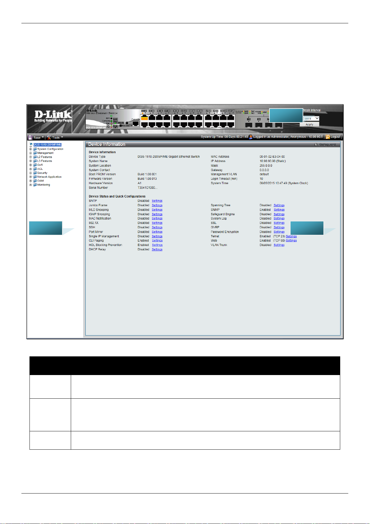
The figure below shows the user interface. Three distinct areas divide the user interface, as described in the table.
Area
Number
Area 1
Area 2
Area 3
Figure 1-2 Main Web-Manager page
Function
Select the menu or window to display. Open folde rs and click the hyperlinked menu buttons
and subfolders contained within them to displ ay menus. Click the D-Link logo to go to the D-
Presents a graphical near real-time image of the front panel of the Switch. This area displays
the Switch's ports, console and management port, showing port activity.
Some management functions, including save, reboot, download and upload are accessible
Presents switch information based on user selection and the entry of configuration data.
6

DGS-1510/ME Series Metro Ethernet Switch Web UI Reference Guide
Web Pages
When connecting to the management mode of the Switch with a web browser, a login screen is displ ayed. Enter a
user name and password to access the Switch's management mode.
Below is a list of the main folders available in the Web interface:
System Configuration - In this section the user will be able to configure features regarding the Switch’s configuration.
Management - In this section the user will be able to configure features regarding the Switch’s m anagement.
L2 Features - In this section the user will be able to configure featu res regarding the Layer 2 functionality of the
Switch.
L3 Features - In this section the user will be able to configure features regarding the Layer 3 functional i ty of the
Switch.
QoS - In this section the user will be able to configu re features regarding the Quality of Service funct ionality of the
Switch.
ACL - In this section the user will be able to confi gure features regarding the Access Control List f unct i onality of the
Switch.
Security - In this section the user will be able to configure features regarding the Switch’s security.
Network Application - In this section the user will be able to configure features regarding networ k applications
handled by the Switch.
OAM - In this section the user will be able to configu re features regarding the Switch’s operations, administration and
maintenance (OAM).
Monitoring - In this section the user will be able to mo ni tor the Switch’s configuration and statistics.
NOTE: Be sure to configure the user name and password in the User Accounts menu bef ore
connecting the Switch to the greater net work.
7
DGS-1510/ME Series Metro Ethernet Switch Web UI Reference Guide
Chapter 2 System Configuration
Device Information
System Information Settings
Port Configuration
PoE
Serial Port Settings
Warning Temperature Settings
System Log Configuration
Time Range Settings
Time Settings
User Accounts Settings
Command Logging Settings
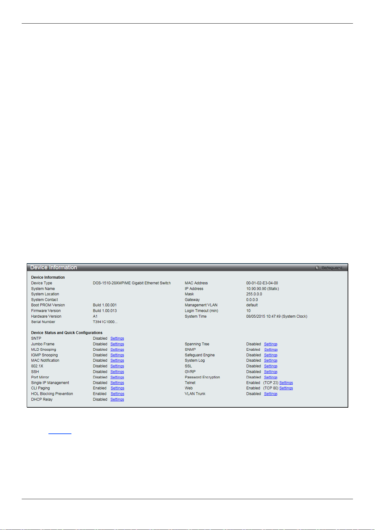
Device Information
This window contains the main settings for al l the major functions for the Switch. It appears automatically when you
log on to the Switch. To return to the Device Informat ion window after viewing other windows, click the DGS-1510/ME
Series link.
The Device Information window shows the Switch’s MAC Address (assigned by the factory and un changeable), the
Boot PROM Version, Firmware Version, Hard ware Version, and many other important types of i nformation. This is
helpful to keep track of PROM and firmware updates and to obtain the Switch’s MAC address f or entry into another
network device’s address table, if necessary. In addition, this window displays the status of f unctions on the Switch to
quickly assess their current global status .
Many functions are hyper-linked for easy access to enable quick configuration from this window.
Figure 2-1 Device Information windo w
Click the Settings link to navigate to the appropriate feature page for configuration.
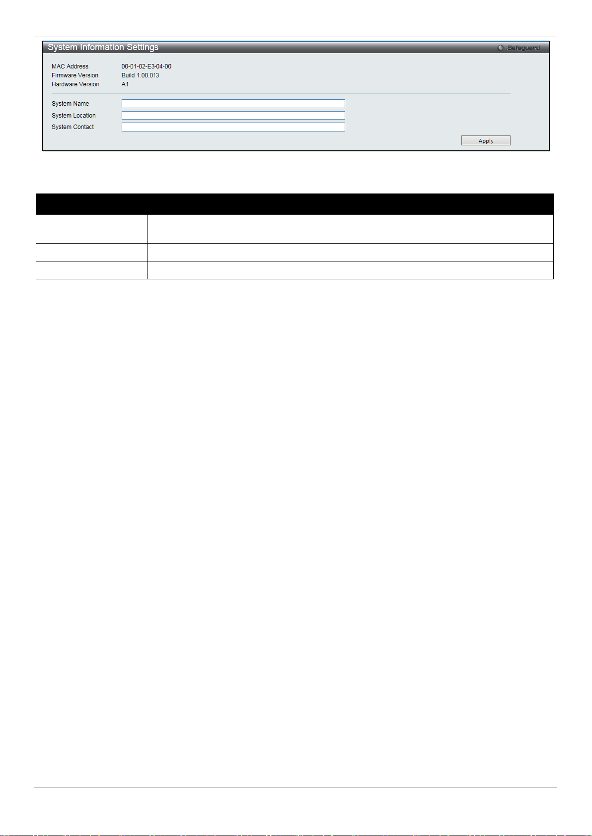
System Information Settings
The user can enter a System Name, System Location, and System Contact to aid in defining the Switch.
To view the following window, click System Configuration > System Information Settings, as show below:
8
DGS-1510/ME Series Metro Ethernet Switch Web UI Reference Guide
network.
System Location
Enter the location of the Switch, if so desired.
System Contact
Enter a contact name for the Switch, if so desired.
Figure 2-2 System Information Settings window
The fields that can be configured are described below:
Parameter Description
System Name
Click the Apply button to implement changes made.
Enter a system name for the Switch, if so desired. This name will identify it in the Switch
Port Configuration
DDM
This folder contains windows that perform Digital Diagnostic Monitoring (DDM) functions on the Switch. There are
windows that allow the user to view the digital diagnostic monitoring status of SFP modules inserting to the Switch and
to configure alarm settings, warning settings, temperature threshold settings, voltage t hreshold settings, bias current
threshold settings, Tx power threshold settings, and Rx power threshold settings.
DDM Settings
The window is used to configure the action that will occur for specific ports when an exceeding alarm threshold or
warning threshold event is encountered.
To view the following window, click System Configuration > Port Configuration > DDM > DDM Settings, as show
below:
9

DGS-1510/ME Series Metro Ethernet Switch Web UI Reference Guide
warning threshold.
warning threshold.
From Port / To Port
Select a range of ports to be configured.
State
Use the drop-down menu to enable or disable the DDM state.
not. This is the default.
Figure 2-3 DDM Settings window
The fields that can be configured are described below:
Parameter Description
Trap State
Log State
Shutdown
Click the Apply button to accept the changes made for each individual section.
Specify whether to send the trap, when the operating parameter exceeds the alarm or
Specify whether to send the log, when the operati ng parameter exceeds the alarm or
Specify whether to shutdown the port, when t he operating parameter exceeds the Alarm or
Warning threshold.
Alarm - Shutdown the port when the configured alarm thres hol d range is exceeded.
Warning - Shutdown the port when the configure d warning threshold range is exceeded.
None - The port will never shutdown regardless if the threshold ranges are exceeded or
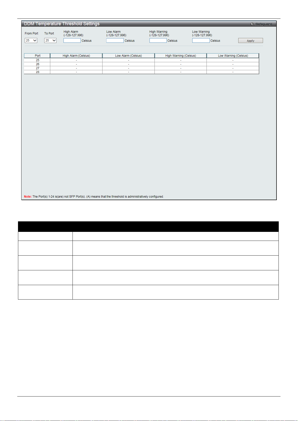
DDM Temperature Threshold Se tti ng s
This window is used to configure the DDM Temperature Threshold Settings for specific ports on the Switch.
To view the following window, click System Configuration > Port Configuration > DDM > DDM Temperature
Threshold Settings, as show below:
10
DGS-1510/ME Series Metro Ethernet Switch Web UI Reference Guide
From Port / To Port
Select a range of ports to be configured.
127.996)
value, action associated with the alarm wil l be taken.
127.996)
value, action associated with the alarm wil l be taken.
127.996)
this value, action associated with the warning will be taken.
127.996)
value, action associated with the warnin g wil l be taken.
Figure 2-4 DDM Temperature Threshold Settings window
The fields that can be configured are described below:
Parameter Description
High Alarm (-128-
Low Alarm (-128-
High Warning (-128-
Low Warning (-128-
Click the Apply button to accept the changes made.
This is the highest threshold for the alarm. When the operating parameter rises above this
This is the lowest threshold for the alarm. When the operating parameter falls below this
This is the highest threshold for the warning. Wh en the operating parameter rises above
This is the lowest threshold for the warning. Whe n the operating parameter falls below this
DDM Voltage Threshold Settings
This window is used to configure the DDM Voltage Threshold Settings for specific ports on the Switch.
To view the following window, click System Configuration > Port Configuration > DDM > DDM Voltage Threshold
Settings, as show below:
11

DGS-1510/ME Series Metro Ethernet Switch Web UI Reference Guide
From Port / To Port
Select a range of ports to be configured.
value, action associated with the alarm wil l be taken.
value, action associated with the alarm wil l be taken.
6.55)
this value, action associated with the warning will be taken.
6.55)
value, action associated with the warnin g wil l be taken.
Figure 2-5 DDM Voltage Threshold Settings window
The fields that can be configured are described below:
Parameter Description
High Alarm (0-6.55)
Low Alarm (0-6.55)
High Warning (0-
Low Warning (0-
Click the Apply button to accept the changes made.
This is the highest threshold for the alarm. When the operating parameter rises above this
This is the lowest threshold for the alarm. When the operating parameter falls below this
This is the highest threshold for the warning. Wh en the operating parameter rises above
This is the lowest threshold for the warning. Whe n the operating parameter falls below this
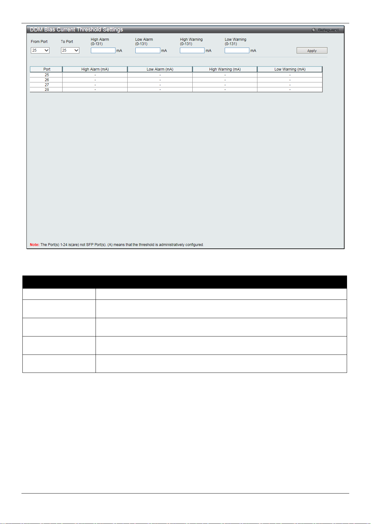
DDM Bias Current Thres hold Settings
This window is used to configure the threshold of the bias current for specific ports on the Switch.
To view the following window, click System Configuration > Port Configuration > DDM > DDM Bias Current
Threshold Settings, as show below:
12
DGS-1510/ME Series Metro Ethernet Switch Web UI Reference Guide
From Port / To Port
Select a range of ports to be configured.
this value, action associated with the alarm will be taken.
value, action associated with the alarm will be taken.
this value, action associated with the warning will be taken.
this value, action associated with the warning will be taken.
Figure 2-6 DDM Bias Current Threshold Settings window
The fields that can be configured are described below:
Parameter Description
High Alarm (0-131)
Low Alarm (0-131)
High Warning (0-131)
Low Warning (0-131)
Click the Apply button to accept the changes made.
This is the highest threshold for the alarm. When the operating parameter rises above
This is the lowest threshold for the alarm. When the operating parameter falls below this
This is the highest threshold for the warning. Wh en the operating parameter rises above
This is the lowest threshold for the warning. When the operating parameter falls below
DDM TX Power Threshold Settings
This window is used to configure the threshold of Tx power for specific ports on the Switch.
To view the following window, click System Configuration > Port Configuration > DDM > DDM TX Power
Threshold Settings, as show below:
13

DGS-1510/ME Series Metro Ethernet Switch Web UI Reference Guide
From Port / To Port
Select a range of ports to be configured.
6.5535)
value, action associated with the alarm wil l be taken.
6.5535)
value, action associated with the alarm wil l be taken.
6.5535)
this value, action associated with the warning will be taken.
6.5535)
value, action associated with the warnin g wil l be taken.
Figure 2-7 DDM TX Power Threshold Settings window
The fields that can be configured are described below:
Parameter Description
High Alarm (0-
Low Alarm (0-
High Warning (0-
Low Warning (0-
Click the Apply button to accept the changes made.
This is the highest threshold for the alarm. When the operating parameter rises above this
This is the lowest threshold for the alarm. When the operating parameter falls below this
This is the highest threshold for the warning. Wh en the operating parameter rises above
This is the lowest threshold for the warning. Whe n the operating parameter falls below this
DDM RX Power Threshold Settings
This window is used to configure the threshold of RX power for specific ports on the Switch.
To view the following window, click System Configuration > Port Configuration > DDM > DDM RX Power
Threshold Settings, as show below:
14

DGS-1510/ME Series Metro Ethernet Switch Web UI Reference Guide
From Port / To Port
Select a range of ports to be configured.
6.5535)
value, action associated with the alarm will be taken.
6.5535)
value, action associated with the alarm wil l be taken.
6.5535)
this value, action associated with the warning will be taken.
6.5535)
value, action associated with the warning will be tak en.
Figure 2-8 DDM RX Power Threshold Settings window
The fields that can be configured are described bel ow:
Parameter Description
High Alarm (0-
Low Alarm (0-
High Warning (0-
Low Warning (0-
Click the Apply button to accept the changes made.
This is the highest threshold for the alarm. When the operating parameter rises above this
This is the lowest threshold for the alarm. When the operating parameter falls below this
This is the highest threshold for the warning. Wh en the operating parameter rises above
This is the lowest threshold for the warning. Whe n the operating parameter falls below this
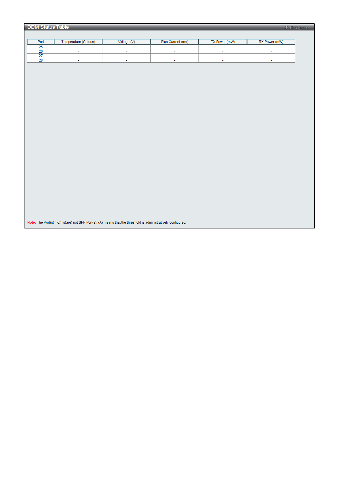
DDM Status Table
This window is used to display the current operating digital diagnostic monitoring parameters and their values on the
SFP module for specified ports.
To view the following window, click System Configuration > Port Configuration > DDM > DDM Status Table, as
show below:
15
DGS-1510/ME Series Metro Ethernet Switch Web UI Reference Guide
Figure 2-9 DDM Status Table window
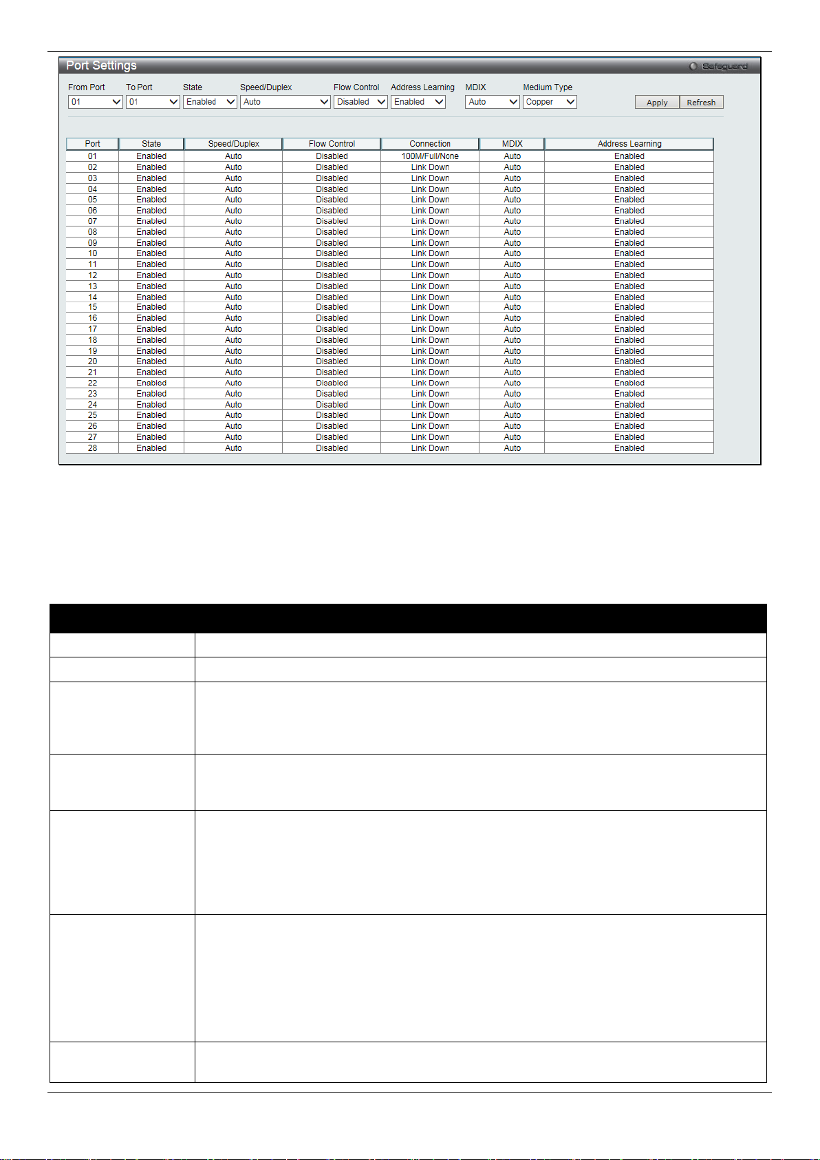
Port Settings
This page used to configure the details of the swit ch ports.
To view the following window, click System Configuration > Port Configuration > Port Settings, as show below:
16
DGS-1510/ME Series Metro Ethernet Switch Web UI Reference Guide
From Port / To Port
Select the appropriate port range used for the configuration here.
State
Toggle the State field to either enable or di sable a given port or group of ports.
available options are Auto, 100M Full, 1000M Full, and 10G Ful l.
Auto ports use an automatic selection of the two. The default is Disabled.
The default setting is Enabled.
cable.
Fiber.
Figure 2-10 Port Settings window
To configure switch ports:
1. Choose the port or sequential range of ports using the From Port and To Port drop-down menus.
2. Use the remaining drop-down menus to configure the parameters described below:
The fields that can be configured are described below:
Parameter Description
Speed/Duplex
Select the speed and full-duplex/half-duplex st ate of the port. When Copper is selected in
Medium Type, the available options are Auto, 10M Half, 10M Full, 100M Half, 100M F ul l,
1000M Full_Master, and 1000M Full_Slave. When Fiber is selected in Medium Type, the
Flow Control
Displays the flow control scheme used for the various port configurations. Ports configur ed
for full-duplex use 802.3x flow control, half-duplex ports use b ackpressure flow control, and
Address Learning
Enable or disable MAC address learning for the selected ports. When Enabled, destination
and source MAC addresses are automatically l i st ed i n the forwarding table. When address
learning is Disabled, MAC addresses must be m anually entered into the forwarding table.
This is sometimes done for reasons of security or efficiency. See the section on
Forwarding/Filtering for information on en tering MAC addresses into the forwarding table.
MDIX
Auto - Select auto for auto sensing of the optimal t ype of cabling.
Normal - Select normal for normal cabling. If this option is selected, the port is in the MDIX
mode and can be connected to a PC’s NIC using a straight-through cable or a port (in the
MDIX mode) on another switch through a cross-over cable.
Cross - Select cross for cross cabling. If this option is selected, the port is in MDI mode,
and can be connected to a port (in the MDIX mode) on anoth er switch through a straight
Medium Type
Select the type of transport medium to be used. Opt i ons to choose from are Copper and
17
DGS-1510/ME Series Metro Ethernet Switch Web UI Reference Guide
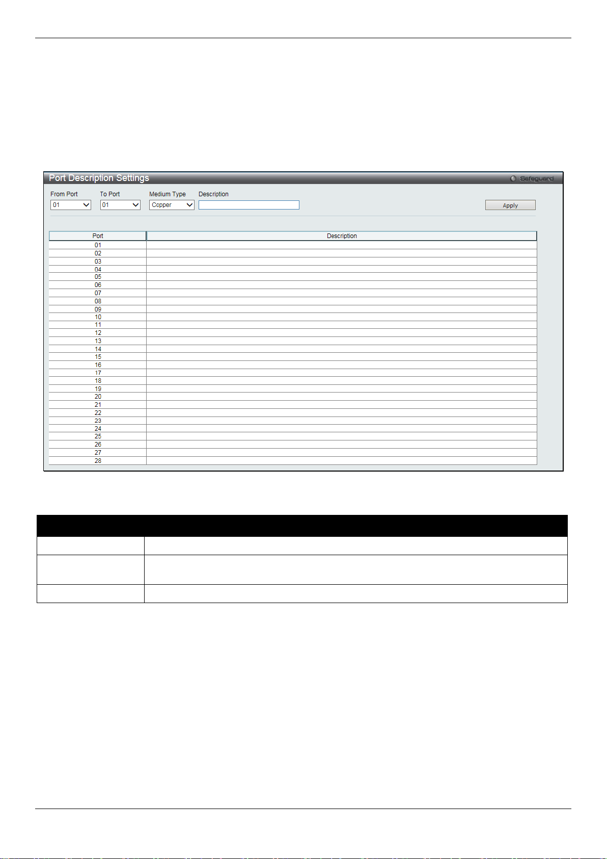
From Port / To Port
Select the appropriate port range used for the configuration here.
Type defines the type of transport medium to be used, whether Copper or Fiber.
Description
Users may then enter a description for the chos en port(s).
Click the Apply button to implement changes made.
Click the Refresh button to refresh the display section of this page.
Port Description Settings
The Switch supports a port description feat ure where the user may name various ports.
To view the following window, click System Configuration > Port Configuration > Port Description Settings, as
show below:
Figure 2-11 Port Description Settings window
The fields that can be configured are described below:
Parameter Description
Medium Type
Click the Apply button to implement changes made.
Specify the medium type for the selected ports. If conf iguring the Combo ports, the Medium
Port Error Disabled
The following window displays the information about ports that have been disconnected by the Switch when a packet
storm occurs or a loop was detected.
To view the following window, click System Configuration > Port Configuration > Port Error Disabled, as show
below:
18

DGS-1510/ME Series Metro Ethernet Switch Web UI Reference Guide
Port
Display the port that has been error disabled.
Port State
Describe the current running state of the port, whet her enabled or disabled.
Connection Status
Display the uplink status of the individual ports, whether enabled or disabled.
shutdown port for storm control.
enabled, the maximum frame size is 9,216 bytes.
Figure 2-12 Port Error Disabled
The fields that can be displayed are described below:
Parameter Description
Reason
Describe the reason why the port has been error-dis abl ed, such as it has become a
Jumbo Frame Settings
The Switch supports jumbo frames. Jumbo f rames are Ethernet frames with more than 1,536 bytes of payload. The
Switch supports jumbo frames with a maximum frame size of up to 9,216 bytes.
To view the following window, click System Configuration > Port Configuration > Jumbo Frame Settings, as show
below:
Figure 2-13 Jumbo Frame Settings window
The fields that can be configured are described below:
Parameter Description
Jumbo Frame
Use the radio buttons to enable or disable the Jumbo Frame function on the Switch. The
default is Disabled. When disabled, the max im um frame size is 1,536 bytes. When
Click the Apply button to implement changes made.
EEE Settings
Energy Efficient Ethernet (EEE) is defined in I EEE 802.3az. It is designed to reduce the energy consumption of a link
when no packets are being sent. EEE and ERPS are mutually exclusive functions.
To view the following window, click System Configuration > Port Configuration > EEE Settings, as shown below:
19
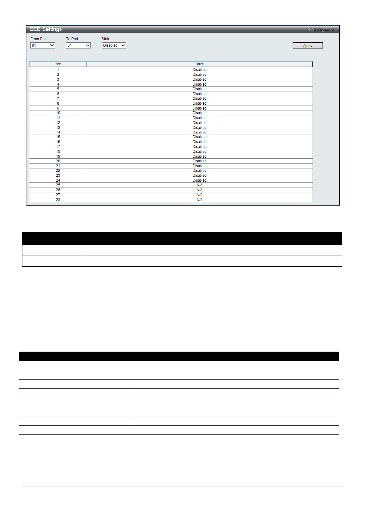
DGS-1510/ME Series Metro Ethernet Switch Web UI Reference Guide
From Port / To Port
Select the appropriate port range used for the configuration here.
State
Select to enable or disable the state of this feature here.
Pin
Alternative
1
Negative Vport
2
Negative Vport
3
Positive Vport
4 5 6
Positive Vport
7 8
Figure 2-14 EEE Settings window
The fields that can be configured are described below:
Parameter Description
Click the Apply button to implement changes made.
PoE
The DGS-1510-28LP/ME and DGS-1510-28XMP/ME switches support Power over Ethernet (PoE) as defined by the
IEEE 802.3af and 802.3at standard. Ports 1 t o 24 for DGS-1510-28LP/ME and DGS-1510-28XMP/ME can supply
about 48 VDC power to Powered Devices (PDs) over Category 5 or Category 3 UTP Ethernet cables.
The Switch follows the standard Power Sourcing Eq ui pment (PSE) pinout Alternative A, whereby power is sent out
over pins 1, 2, 3 and 6. The Switches work with all D-Link 802.3af capable devices.
The Switch includes the following PoE features:
• Auto-discovery recognizes the connection of a Powered Device (PD) and automatically sends power t o i t.
• The Auto-disable function will activate when the port current value exceeds 350mA or when a short happens.
20

DGS-1510/ME Series Metro Ethernet Switch Web UI Reference Guide
Class
Usage
Minimum output power levels of PSE devices
0
Default
15.4 Watt
1
Optional
4.0 Watt
2
Optional
7.0 Watt
3
Optional
15.4 Watt
4
Reserved
Treat as Class 0
Class
Usage
Minimum output power levels of PSE devices
0
Default
15.4 Watt
1
Optional
4.0 Watt
2
Optional
7.0 Watt
3
Optional
15.4 Watt
4
Optional
15.4 or 30 Watt
Type 2 = 30 Watt.
For 802.3af capable devices, evaluate the t able below, containing the correct power level per class and their
respective usage options.
For 802.3at capable devices, evaluate the t able below, containing the correct power level per class and their
respective usage options. This feature prov i des power allocation of 0.1 Watt granularity, using the LLDP method.
NOTE: Class 4 devices use the following equatio n:
Ptype=Icable x V Port_PSE min
Type 1 = 15.4 Watt.
To configure the PoE features on the Switch, click System Configuration > PoE.
PoE System Settings
This window is used to assign a power limit and power disconnect method for the whole PoE system. When the total
consumed power exceeds the power limit configured in this window, the PoE controller (located in the PSE)
disconnects the power to prevent overloading t he power supply.
To view the following window, click System Configuration > PoE > PoE System Settings, as show below:
21
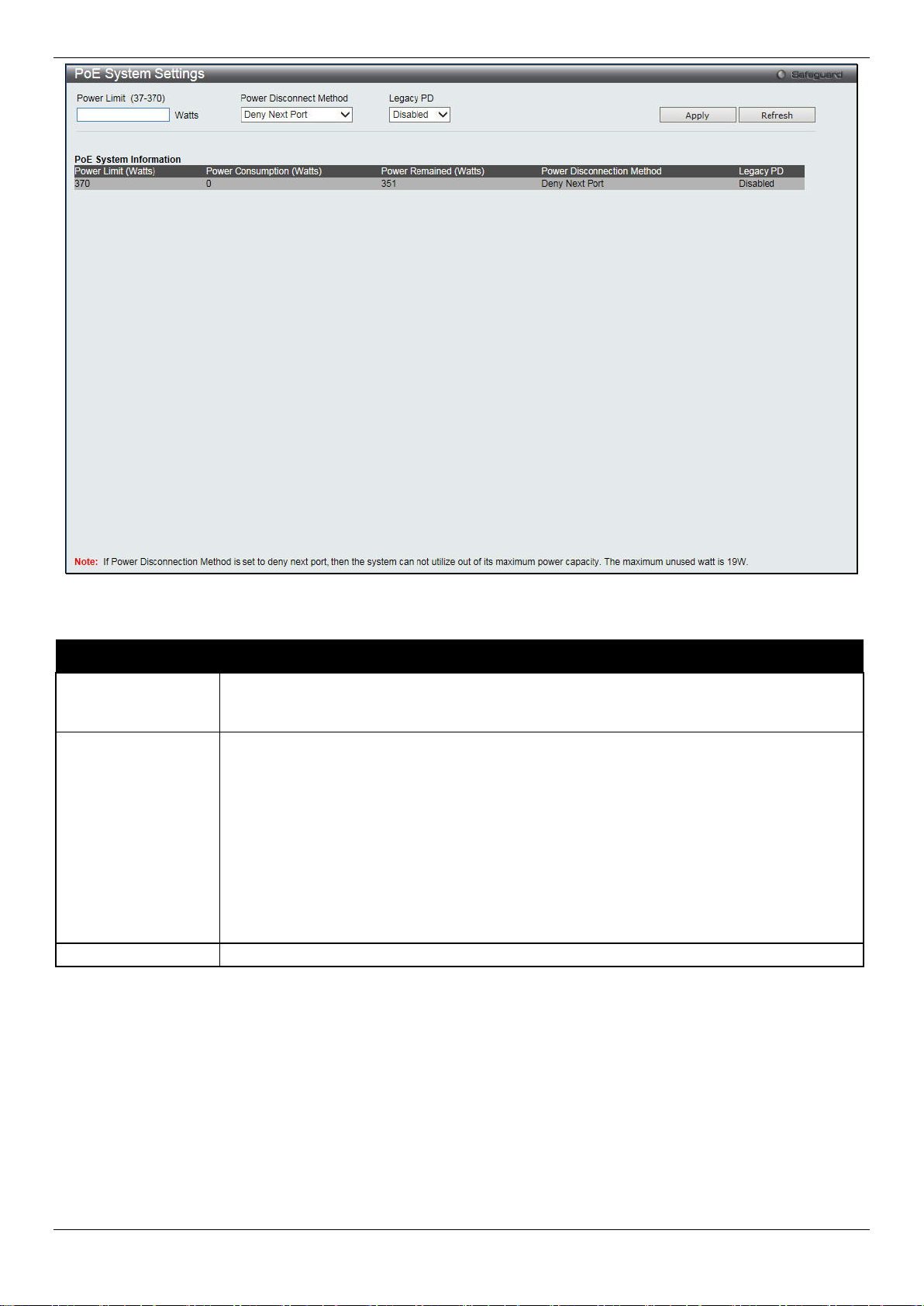
DGS-1510/ME Series Metro Ethernet Switch Web UI Reference Guide
between 37W and 370W for DGS-1510-28XMP/ME.
priority and critical priority ports to power up.
Legacy PD
Use the drop-down menu to enable or disable detecting legacy PDs signal.
Figure 2-15 PoE System Settings window
The following parameters can be configured:
Parameter Description
Power Limit
Power Disconnect
Method
Click Apply to implement changes made.
Sets the limit of power to be used from the Switch’ s power source to PoE ports. The user
may configure a Power Limit between 37W and 193W for DGS-1510-28LP/ME, and
The PoE controller uses either Deny Next Port or Deny Low Priority Port to offset t he power
limit being exceeded and keeps the Switch’s power at a usable level. Use the drop down
menu to select a Power Disconnect Method. The default P ower Disconnect Method is
Deny Next Port. Both Power Disconnection Met hods are described below:
Deny Next Port – After the power limit has been exceeded, the next port attempting to
power up is denied, regardless of its priority. If Power Disconnection Method is set to Deny
Next Port, the system cannot utilize out of its maximum power capacity. The maximum
unused watt is 10W for DGS-1510-28LP/ME and 19W for DGS-1510-28XMP/ME.
Deny Low Priority Port – After the power limit has been exceeded, the next port attempting
to power up causes the port with the lowest priorit y to shut down so as to allow the high-
PoE Port Settings
To view the following window, click System Configuration > PoE > PoE Port Settings, as show below:
22
 Loading...