

D-link DGS-1510-10L, DGS-1510-28L, DGS-1510-28XMP, DGS-1510-28X, DGS-1510-28XS User Manual [ru]
...Page 1
Page 2

DGS-1510/ME Series Metro Ethernet Switch Web UI Reference Guide
Information in this document is subject to change without notice.
© 2015 D-Link Corporation. All rights reserved.
Reproduction of this document in any manner whatsoever without the written permission of D-Link Corporation is strictly forbidden.
Trademarks used in this text: D-Link and the D-LINK logo are trademarks of D-Link Corporation; Microsoft and Windows are registered trademarks
of Microsoft Corporation.
Other trademarks and trade names may be used in this document to refer to either the entities claiming the marks and names or their products. D-
Link Corporation disclaims any proprietary interest in trademarks and trade names other than its own.
July 2015 P/N 651GS15ME015G
i
Page 3

DGS-1510/ME Series Metro Ethernet Switch Web UI Reference Guide
Table of Contents
Intended Readers ........................................................................................................................................................... 1
Typographical Conventions ............................................................................................................................................ 1
Notes, Notices and Cautions .......................................................................................................................................... 1
Safety Instructions .......................................................................................................................................................... 2
Safety Cautions ........................................................................................................................................................... 2
General Precautions for Rack-Mountable P roducts ....................................................................................................... 2
Protecting Against Electrostatic Discharg e .................................................................................................................... 3
Chapter 1 Web-based Switch Configuration ........................................................................... 5
Introduction ..................................................................................................................................................................... 5
Login to the Web Manager ............................................................................................................................................. 5
Web-based User Interface .............................................................................................................................................. 6
Areas of the User Interface ......................................................................................................................................... 6
Web Pages ..................................................................................................................................................................... 7
Chapter 2 System Configuration .............................................................................................. 8
Device Information .......................................................................................................................................................... 8
System Information Settings ........................................................................................................................................... 8
Port Configuration ........................................................................................................................................................... 9
DDM ............................................................................................................................................................................ 9
Port Settings ............................................................................................................................................................. 16
Port Description Settings .......................................................................................................................................... 18
Port Error Disabled ................................................................................................................................................... 18
Jumbo Frame Settings .............................................................................................................................................. 19
EEE Settings ............................................................................................................................................................. 19
PoE ............................................................................................................................................................................... 20
PoE System Settings ................................................................................................................................................ 21
PoE Port Settings ...................................................................................................................................................... 22
Serial Port Settings ....................................................................................................................................................... 24
Warning Temperature Settings .................................................................................................................................... 24
System Log Configuration ............................................................................................................................................ 25
System Log Settings ................................................................................................................................................. 25
System Log Server Settings ..................................................................................................................................... 26
System Log ............................................................................................................................................................... 26
System Log & Trap Settings ..................................................................................................................................... 27
System Severity Settings .......................................................................................................................................... 27
Time Range Settings .................................................................................................................................................... 28
Time Settings ................................................................................................................................................................ 29
User Accounts Settings ................................................................................................................................................ 29
Command Logging Settings ......................................................................................................................................... 30
Chapter 3 Management ........................................................................................................... 31
ARP .............................................................................................................................................................................. 31
Static ARP Settings ................................................................................................................................................... 31
ARP Table ................................................................................................................................................................. 31
Gratuitous ARP ............................................................................................................................................................. 32
Gratuitous ARP Global Settings ............................................................................................................................... 32
Gratuitous ARP Settings ........................................................................................................................................... 33
IPv6 Neighbor Settings ................................................................................................................................................. 33
IP Interface ................................................................................................................................................................... 34
System IP Address Settings ..................................................................................................................................... 34
ii
Page 4

DGS-1510/ME Series Metro Ethernet Switch Web UI Reference Guide
Interface Settings ...................................................................................................................................................... 36
Management Settings ................................................................................................................................................... 38
Session Table ............................................................................................................................................................... 39
Single IP Management ................................................................................................................................................. 39
Single IP Settings ...................................................................................................................................................... 41
Topology ................................................................................................................................................................... 42
Firmware Upgrade .................................................................................................................................................... 48
Configuration File Backup/Restore ........................................................................................................................... 48
Upload Log File ......................................................................................................................................................... 49
SNMP Settings ............................................................................................................................................................. 49
SNMP Global Settings .............................................................................................................................................. 50
SNMP Traps Settings ............................................................................................................................................... 51
SNMP Linkchange Traps Settings ............................................................................................................................ 51
SNMP View Table Settings ....................................................................................................................................... 52
SNMP Community Table Settings ............................................................................................................................ 53
SNMP Group Table Settings..................................................................................................................................... 54
SNMP Engine ID Settings ......................................................................................................................................... 54
SNMP User Table Settings ....................................................................................................................................... 55
SNMP Host Table Settings ....................................................................................................................................... 56
RMON Settings ......................................................................................................................................................... 56
Telnet Settings .............................................................................................................................................................. 57
Web Settings ................................................................................................................................................................ 57
Chapter 4 L2 Features ............................................................................................................. 59
VLAN ............................................................................................................................................................................ 59
802.1Q VLAN Settings .............................................................................................................................................. 64
802.1v Protocol VLAN ............................................................................................................................................... 67
GVRP ........................................................................................................................................................................ 69
MAC-based VLAN Settings ....................................................................................................................................... 71
PVID Auto Assign Settings ....................................................................................................................................... 71
VLAN Trunk Settings ................................................................................................................................................ 71
Browse VLAN ............................................................................................................................................................ 72
Show VLAN Ports ..................................................................................................................................................... 73
QinQ ............................................................................................................................................................................. 73
QinQ Settings ............................................................................................................................................................ 75
VLAN Translation Settings ........................................................................................................................................ 75
Layer 2 Protocol Tunneling Settings ............................................................................................................................ 76
Spanning Tree .............................................................................................................................................................. 77
STP Bridge Global Settings ...................................................................................................................................... 79
STP Port Settings ..................................................................................................................................................... 80
MST Configuration Identification ............................................................................................................................... 81
STP Instance Settings .............................................................................................................................................. 82
MSTP Port Information ............................................................................................................................................. 82
Link Aggregation ........................................................................................................................................................... 83
Port Trunking Settings .............................................................................................................................................. 85
LACP Port Settings ................................................................................................................................................... 86
FDB ............................................................................................................................................................................... 87
Static FDB Settings ................................................................................................................................................... 87
MAC Notification Settings ......................................................................................................................................... 88
MAC Address Aging Time Settings .......................................................................................................................... 89
MAC Address Table .................................................................................................................................................. 89
ARP & FDB Table ..................................................................................................................................................... 90
iii
Page 5

DGS-1510/ME Series Metro Ethernet Switch Web UI Reference Guide
L2 Multicast Control ...................................................................................................................................................... 91
IGMP Snooping ......................................................................................................................................................... 91
MLD Snooping .......................................................................................................................................................... 99
Multicast VLAN ....................................................................................................................................................... 107
Multicast Filtering ........................................................................................................................................................ 110
IPv4 Multicast Filtering ............................................................................................................................................ 110
IPv6 Multicast Filtering ............................................................................................................................................ 112
Multicast Filtering Mode .......................................................................................................................................... 114
ERPS Settings ............................................................................................................................................................ 115
LLDP ........................................................................................................................................................................... 117
LLDP ....................................................................................................................................................................... 118
LLDP-MED .............................................................................................................................................................. 126
NLB FDB Settings ...................................................................................................................................................... 128
Chapter 5 L3 Features ........................................................................................................... 130
IPv4 Static/Default Route Settings ............................................................................................................................. 130
IPv4 Route Table ........................................................................................................................................................ 130
IPv6 Static/Default Route Settings ............................................................................................................................. 131
Chapter 6 QoS ........................................................................................................................ 132
802.1p Settings ........................................................................................................................................................... 133
802.1p Default Priority Settings .............................................................................................................................. 133
802.1p User Priority Settings .................................................................................................................................. 134
802.1p Map Settings ............................................................................................................................................... 135
Bandwidth Control ...................................................................................................................................................... 135
Bandwidth Control Settings ..................................................................................................................................... 135
Queue Bandwidth Control Settings ......................................................................................................................... 136
Traffic Control Settings ............................................................................................................................................... 137
DSCP .......................................................................................................................................................................... 140
DSCP Trust Settings ............................................................................................................................................... 140
DSCP Map Settings ................................................................................................................................................ 140
HOL Blocking Prevention ........................................................................................................................................... 142
Scheduling Settings .................................................................................................................................................... 143
QoS Scheduling ...................................................................................................................................................... 143
QoS Scheduling Mechanism................................................................................................................................... 144
Chapter 7 ACL ........................................................................................................................ 146
ACL Configuration Wizard .......................................................................................................................................... 146
Access Profile List ...................................................................................................................................................... 147
Add an Ethernet ACL Profile ................................................................................................................................... 148
Adding an IPv4 ACL Profile .................................................................................................................................... 151
Adding an IPv6 ACL Profile .................................................................................................................................... 156
Adding a Packet Content ACL Profile ..................................................................................................................... 161
CPU Access Profile List .............................................................................................................................................. 164
Adding a CPU Ethernet ACL Profile ....................................................................................................................... 165
Adding a CPU IPv4 ACL Profile .............................................................................................................................. 168
Adding a CPU IPv6 ACL Profile .............................................................................................................................. 172
Adding a CPU Packet Content ACL Profile ............................................................................................................ 175
ACL Finder.................................................................................................................................................................. 178
ACL Flow Meter .......................................................................................................................................................... 179
Chapter 8 Security ................................................................................................................. 182
802.1X ........................................................................................................................................................................ 182
802.1X Global Settings ........................................................................................................................................... 187
802.1X Port Settings ............................................................................................................................................... 188
iv
Page 6

DGS-1510/ME Series Metro Ethernet Switch Web UI Reference Guide
802.1X User Settings .............................................................................................................................................. 190
Guest VLAN Settings .............................................................................................................................................. 191
Authenticator State ................................................................................................................................................. 192
Authenticator Statistics ........................................................................................................................................... 192
Authenticator Session Statistics ............................................................................................................................. 193
Authenticator Diagnostics ....................................................................................................................................... 194
Initialize Port(s) ....................................................................................................................................................... 195
Reauthenticate Port(s) ............................................................................................................................................ 196
RADIUS ...................................................................................................................................................................... 197
Authentication RADIUS Server Settings ................................................................................................................. 197
RADIUS Accounting Settings.................................................................................................................................. 197
RADIUS Authentication ........................................................................................................................................... 198
RADIUS Account Client .......................................................................................................................................... 200
IP-MAC-Port Binding (IMPB) ...................................................................................................................................... 202
IMPB Global Settings .............................................................................................................................................. 202
IMPB Port Settings .................................................................................................................................................. 203
IMPB Entry Settings ................................................................................................................................................ 204
MAC Block List ........................................................................................................................................................ 204
DHCP Snooping ...................................................................................................................................................... 205
MAC-based Access Control (MAC) ............................................................................................................................ 206
MAC-based Access Control Settings ...................................................................................................................... 206
MAC-based Access Control Local Settings ............................................................................................................ 208
MAC-based Access Control Authentication Stat e .................................................................................................. 209
Compound Authentication .......................................................................................................................................... 209
Compound Authentication Settings ........................................................................................................................ 210
Port Security ............................................................................................................................................................... 210
Port Security Settings ............................................................................................................................................. 210
Port Security VLAN Settings ................................................................................................................................... 212
Port Security Entries ............................................................................................................................................... 213
ARP Spoofing Prevention Settings ............................................................................................................................. 213
BPDU Attack Protection ............................................................................................................................................. 214
Loopback Detection Settings ...................................................................................................................................... 215
Traffic Segmentation Settings .................................................................................................................................... 216
NetBIOS Filtering Settings .......................................................................................................................................... 217
DHCP Server Screening ............................................................................................................................................. 218
DHCP Server Screening Port Settings ................................................................................................................... 218
DHCP Offer Permit Entry Settings .......................................................................................................................... 219
Access Authentication Control.................................................................................................................................... 220
Enable Admin .......................................................................................................................................................... 221
Authentication Policy Settings ................................................................................................................................ 221
Application Authentication Settings ........................................................................................................................ 222
Authentication Server Group Settings .................................................................................................................... 223
Authentication Server Settings ............................................................................................................................... 224
Login Method Lists Settings .................................................................................................................................... 225
Enable Method Lists Settings ................................................................................................................................. 226
Local Enable Password Settings ............................................................................................................................ 227
SSL Settings ............................................................................................................................................................... 228
SSH ............................................................................................................................................................................ 230
SSH Settings ........................................................................................................................................................... 230
SSH Authentication Method and Algorithm Settings .............................................................................................. 231
SSH User Authentication List.................................................................................................................................. 233
v
Page 7

DGS-1510/ME Series Metro Ethernet Switch Web UI Reference Guide
Trusted Host Settings ................................................................................................................................................. 233
Safeguard Engine Settings ......................................................................................................................................... 234
DoS Attack Prevention Settings ................................................................................................................................. 236
IGMP Access Control Settings ................................................................................................................................... 237
Chapter 9 Network Application ............................................................................................ 239
DHCP .......................................................................................................................................................................... 239
DHCP Relay ............................................................................................................................................................ 239
DHCP Local Relay Settings .................................................................................................................................... 245
DHCP Local Relay Option 82 Settings ................................................................................................................... 245
PPPoE Circuit ID Insertion Settings ........................................................................................................................... 246
SMTP Settings ............................................................................................................................................................ 247
SNTP .......................................................................................................................................................................... 248
SNTP Settings ........................................................................................................................................................ 248
Time Zone Settings ................................................................................................................................................. 249
Flash File System Settings ......................................................................................................................................... 251
Chapter 10 OAM ....................................................................................................................... 253
CFM ............................................................................................................................................................................ 253
CFM Settings .......................................................................................................................................................... 253
CFM Port Settings ................................................................................................................................................... 257
CFM MIPCCM Table ............................................................................................................................................... 258
CFM Loopback Settings .......................................................................................................................................... 258
CFM Linktrace Settings ........................................................................................................................................... 259
CFM Packet Counter .............................................................................................................................................. 260
CFM Fault Table ..................................................................................................................................................... 261
CFM MP Table ........................................................................................................................................................ 262
Ethernet OAM ............................................................................................................................................................. 262
Ethernet OAM Settings ........................................................................................................................................... 262
Ethernet OAM Configuration Settings ..................................................................................................................... 263
Ethernet OAM Event Log ........................................................................................................................................ 264
Ethernet OAM Statistics .......................................................................................................................................... 265
DULD Settings ............................................................................................................................................................ 266
Cable Diagnostics ....................................................................................................................................................... 267
Chapter 11 Monitoring ............................................................................................................ 269
Utilization .................................................................................................................................................................... 269
CPU Utilization ........................................................................................................................................................ 269
DRAM & Flash Utilization ........................................................................................................................................ 269
Port Utilization ......................................................................................................................................................... 270
Statistics ..................................................................................................................................................................... 270
Port Statistics .......................................................................................................................................................... 271
Packet Size ............................................................................................................................................................. 278
Mirror .......................................................................................................................................................................... 280
Port Mirror Settings ................................................................................................................................................. 280
Ping Test ..................................................................................................................................................................... 281
Trace Route ................................................................................................................................................................ 282
Peripheral ................................................................................................................................................................... 283
Device Environment ................................................................................................................................................ 283
Chapter 12 Save and Tools ..................................................................................................... 284
Save Configuration / Log ............................................................................................................................................ 284
Download firmware ..................................................................................................................................................... 284
Download Firmware From TFTP ............................................................................................................................ 284
Download Firmware From FTP ............................................................................................................................... 285
vi
Page 8

DGS-1510/ME Series Metro Ethernet Switch Web UI Reference Guide
Download Firmware From HTTP ............................................................................................................................ 286
Upload Firmware ........................................................................................................................................................ 286
Upload Firmware To TFTP ..................................................................................................................................... 286
Upload Firmware To FTP ........................................................................................................................................ 286
Download Configuration ............................................................................................................................................. 287
Download Configuration From TFTP ...................................................................................................................... 287
Download Configuration From FTP ........................................................................................................................ 288
Download Configuration From HTTP ...................................................................................................................... 288
Upload Configuration .................................................................................................................................................. 289
Upload Configuration To TFTP ............................................................................................................................... 289
Upload Configuration To FTP ................................................................................................................................. 289
Upload Configuration To HTTP .............................................................................................................................. 290
Upload Log File .......................................................................................................................................................... 290
Upload Log To TFTP .............................................................................................................................................. 290
Upload Log To FTP ................................................................................................................................................. 291
Upload Log To HTTP .............................................................................................................................................. 291
Reset .......................................................................................................................................................................... 292
Reboot System ........................................................................................................................................................... 292
Appendix A Password Recovery Procedure .......................................................................... 294
Appendix B System Log Entries .............................................................................................. 295
Appendix C Trap Log Entries........................................................... Error! Bookmark not defined.
Appendix D RADIUS Attributes Assignment .................................. Error! Bookmark not defined.
Appendix E IETF RADIUS Attributes Support ................................ Err or ! Bookmark not defined.
vii
Page 9

DGS-1510/ME Series Metro Ethernet Switch Web UI Reference Guide
Typewriter Font
Intended Readers
Intended Readers
Typographical Conventions
Notes, Notices and Cautions
Safety Instructions
General Precautions for Rack-Mountable Products
Protecting Against Electrostatic Discharge
The <Product Code> Series Web UI Reference Gui de contains information for setup and management of the
Switch. This manual is intended for network managers familiar with network management co ncepts and terminology.
Typographical Conventions
Convention Description
[ ] In a command line, square brackets indicate an o ptional entry. For example: [copy
filename] means that optionally you can type copy followed by the name of the file.
Do not type the brackets.
Bold font
Boldface
Initial capital letter Indicates a window name. Names of keys on the keyboard have initial capitals. For
Menu Name > Menu
Option
Indicates a button, a toolbar icon, menu, or menu item. For example: Open the File
menu and choose Cancel. Used for emphasis. May also indicate system messages
or prompts appearing on screen. For example: You have mail. Bold font is also
used to represent filenames, program names a nd commands. For example: use the
copy command.
Indicates commands and responses to prompts that must be typed exactly as printed
in the manual.
example: Click Enter.
Menu Name > Menu Option Indicates the menu structure. Device > Port > Port
Properties means the Port Properties menu option under t he Port menu option that
is located under the Device menu.
Notes, Notices and Cautions
A NOTE indicates important information that hel ps make better use of the device.
A NOTICE indicates either potential damage to hardware or l oss of data and tells how to avoid the
problem.
A CAUTION indicates a potential for pro perty damage, personal injury, or death.
1
Page 10

DGS-1510/ME Series Metro Ethernet Switch Web UI Reference Guide
Safety Instructions
Use the following safety guidelines to ensure your own personal safety and to help protect your system from potential
damage. Throughout this safety section, the caution icon (
to be reviewed and followed.
Safety Cautions
To reduce the risk of bodily injury, electrical shock, fire, and damage to the equipment observe the f ol lowi ng
precautions:
• Observe and follow service markings.
• Do not service any product except as explained in the system documentation.
• Opening or removing covers that are marked with the triangular symbol with a lightning bolt may expose the
user to electrical shock.
o Only a trained service technician should service components inside these compartments.
• If any of the following conditions occur, unplug t he product from the electrical outlet and replace the part or
contact your trained service provider:
o Damage to the power cable, extension cable, or plug.
o An object has fallen into the product.
o The product has been exposed to water.
o The product has been dropped or damaged.
o The product does not operate correctly when t he operating instructions are correctly followed.
• Keep your system away from radiators and heat sou rces. Also, do not block cooling vents.
• Do not spill food or liquids on system components, and never operate the product in a wet environment. If the
system gets wet, see the appropriate section in the troubleshooting guide or contact your trained service
provider.
• Do not push any objects into the openings of the sy stem. Doing so can cause fire or electric shock by shorting
out interior components.
• Use the product only with approved equipment.
• Allow the product to cool before removing covers or touching internal components.
• Operate the product only from the type of external power source indicated on the electrical ratings label. If
unsure of the type of power source required, consult your service provider or local power company.
• To help avoid damaging the system, be sure the voltage selection switch (if provided) on the power supply is
set to match the power available at the Switch’s location:
o 115 volts (V)/60 hertz (Hz) in most of North and S outh America and some Far Eastern countries such
as South Korea and Taiwan
o 100 V/50 Hz in eastern Japan and 100 V/60 Hz in west ern Japan
o 230 V/50 Hz in most of Europe, the Middle East, and the Far East
• Also, be sure that attached devices are electri call y rated to operate with the power available in your location.
• Use only approved power cable(s). If you hav e not been provided with a power cable for your system or for any
AC-powered option intended for your system, purchase a power cable that is approved for use in your country.
The power cable must be rated for the product and for the voltage and current marked on the product's
electrical ratings label. The voltage and current rating of the cable should be greater than the ratings marked
on the product.
• To help prevent electric shock, plug the system and peripheral power cables into properly grounded electrical
outlets. These cables are equipped with three-prong plugs to help ensure proper grounding. Do not use
adapter plugs or remove the grounding prong from a cable. If using an extension cable is nece ss ary, use a 3wire cable with properly grounded plugs.
• Observe extension cable and power strip rati ngs. Make sure that the total ampere rating of al l products
plugged into the extension cable or power strip does not exceed 80 percent of the ampere rat ings l im i t for the
extension cable or power strip.
• To help protect the system from sudden, transient increases and decreases in electrical powe r, use a surge
suppressor, line conditioner, or uninterruptible power supply (UPS).
) is used to indicate cautions and precautions that need
2
Page 11
DGS-1510/ME Series Metro Ethernet Switch Web UI Reference Guide
注意:
one extended component could cause the rack to tip over and may result in serious injury.
uncertain that suitable grounding is available.
• Position system cables and power cables carefully ; route cables so that they cannot be stepped on or t ripped
over. Be sure that nothing rests on any cable s.
• Do not modify power cables or plugs. Consult a lice nsed electrician or your power company for site
modifications. Always follow your local/n ational wiring rules.
• When connecting or disconnecting power to hot-pluggable power supplies, if offered with you r sy st em , observe
the following guidelines:
o Install the power supply before connecting the power cable to the power supply.
o Unplug the power cable before removing the power supply.
o If the system has multiple sources of power, disconnect power from the system by unplugging all
power cables from the power supplies.
• Move products with care; ensure that all caster s and/ or stabilizers are firmly connected to the sy stem. Avoid
sudden stops and uneven surfaces.
CAUTION: Risk of explosion if the battery is replaced by an incorrect battery type. Dispose of used
batteries according to the instructions.
ATTENTION: Risque d'explosion si la batterie est remplacée par un type incorrect. Jetez les piles
usagées selon les instructions.
如果更換不正確之電池型式會有爆炸的風險, 請依製造商說明書處理用過之電池。
General Precautions for Rack-Mountable Products
Observe the following precautions for rack st abi li ty and safety. Also, refer to the rack installation documentation
accompanying the system and the rack for specific caution statements and procedures.
• Systems are considered to be components in a ra ck. Thus, "component" refers to any system as well as to
various peripherals or supporting hardware.
CAUTION: Installing systems in a rac k wit hout the front and side stabilizers installed could cause the rack
to tip over, potentially resulting in bodily injury under certain circumstances. Therefore, always install the
stabilizers before installing components i n the rack. After installing system/components in a rack, never
pull more than one component out of the rack on its slide assemblies at one time. The weight of more t han
• Before working on the rack, make sure that the st abi l i zers are secured to the rack, extended to the floor, and
that the full weight of the rack rests on the f l oor. Install front and side stabilizers on a single rack or front
stabilizers for joined multiple racks befor e wor king on the rack.
• Always load the rack from the bottom up, and load the heaviest item in the rack first.
• Make sure that the rack is level and stable befor e extending a component from the rack.
• Use caution when pressing the component rail release latches and sliding a component into or out of a rack;
the slide rails can pinch your fingers.
• After a component is inserted into the rack, c arefully extend the rail into a locking position, and then slide the
component into the rack.
• Do not overload the AC supply branch circuit that provides power to the rack. The total rack load should not
exceed 80 percent of the branch circuit rating.
• Ensure that proper airflow is provided to comp onents in the rack.
• Do not step on or stand on any component when servicing other components in a rack.
NOTE: A qualified electrician must perform all connections to DC power and to safety grounds. All
electrical wiring must comply with applicabl e l ocal or national codes and practices.
CAUTION: Never defeat the ground conductor or operate the equipment in the absence of a suitably
installed ground conductor. Contact the appropriate electrical inspection authority or an el ectrician if
3
Page 12

DGS-1510/ME Series Metro Ethernet Switch Web UI Reference Guide
ground cable is omitted or disconnected.
CAUTION: The system chassis must be positively grounded to the rack cabinet frame. Do not attempt to
connect power to the system until grounding cables are connected. Completed power and safety ground
wiring must be inspected by a qualified electrical i nspector. An energy hazard will exist if the safety
Protecting Against Electrostatic Discharge
Static electricity can harm delicate compone nts inside the system. To prevent static damage, di scharge static
electricity from your body before touching any of the electronic components, such as the microprocessor. This can be
done by periodically touching an unpainted met al surface on the chassis.
The following steps can also be taken prevent damage from electrostatic discharge (ESD):
1. When unpacking a static-sensitive component from i ts shipping carton, do not remove the component f rom
the antistatic packing material until read y to install the component in the system. Just before unwrapping the
antistatic packaging, be sure to discharge st atic electricity from your body.
2. When transporting a sensitive component, first place it in an antistatic container or packaging.
3. Handle all sensitive components in a static-safe area. If possible, use antistatic floor pads, workbench pads
and an antistatic grounding strap.
4
Page 13

DGS-1510/ME Series Metro Ethernet Switch Web UI Reference Guide
Chapter 1 Web-based Switch Configuration
Introduction
Login to the Web Manager
Web-based User Interface
Web Pages
Introduction
Most software functions of the DGS-1510/ME Series switches can be managed, configured and monitored via the
embedded web-based (HTML) interface. Manage the Switch from remote stations anywhere on t he network through a
standard browser. The browser acts as a universal access tool and can communicate directly with the Switch using
the HTTP protocol.
The Web-based management module and the Console program (and Telnet) are different ways t o acc ess the same
internal switching software and configure i t. Thus, all settings encountered in web-based manageme nt are the same
as those found in the console program.
Login to the Web Manager
To begin managing the Switch, simply run the brows er installed on your computer and point it to the IP address you
have defined for the device. The URL in the address b ar should read something like: http://123.123.123.123, where
the numbers 123 represent the IP address of the Switch.
NOTE: The factory default IP address is 10.90.90.90.
This opens the management module's user authentication window, as seen below.
Figure 1-1 Web UI Login Window
Leave both the User Name field and the Password field blank and click OK. This will open the Web-based user
interface. The Switch management featu res av ailable in the web-based manager are explained below.
5
Page 14
DGS-1510/ME Series Metro Ethernet Switch Web UI Reference Guide
Link website.
here.
AREA 2
AREA 1
AREA 3
Web-based User Interface
The user interface provides access to variou s S witch configuration and management windows, all ows you to view
performance statistics, and permits you to graphically monitor the system status.
Areas of the User Interface
The figure below shows the user interface. Three distinct areas divide the user interface, as described in the table.
Area
Number
Area 1
Area 2
Area 3
Figure 1-2 Main Web-Manager page
Function
Select the menu or window to display. Open folde rs and click the hyperlinked menu buttons
and subfolders contained within them to displ ay menus. Click the D-Link logo to go to the D-
Presents a graphical near real-time image of the front panel of the Switch. This area displays
the Switch's ports, console and management port, showing port activity.
Some management functions, including save, reboot, download and upload are accessible
Presents switch information based on user selection and the entry of configuration data.
6
Page 15

DGS-1510/ME Series Metro Ethernet Switch Web UI Reference Guide
Web Pages
When connecting to the management mode of the Switch with a web browser, a login screen is displ ayed. Enter a
user name and password to access the Switch's management mode.
Below is a list of the main folders available in the Web interface:
System Configuration - In this section the user will be able to configure features regarding the Switch’s configuration.
Management - In this section the user will be able to configure features regarding the Switch’s m anagement.
L2 Features - In this section the user will be able to configure featu res regarding the Layer 2 functionality of the
Switch.
L3 Features - In this section the user will be able to configure features regarding the Layer 3 functional i ty of the
Switch.
QoS - In this section the user will be able to configu re features regarding the Quality of Service funct ionality of the
Switch.
ACL - In this section the user will be able to confi gure features regarding the Access Control List f unct i onality of the
Switch.
Security - In this section the user will be able to configure features regarding the Switch’s security.
Network Application - In this section the user will be able to configure features regarding networ k applications
handled by the Switch.
OAM - In this section the user will be able to configu re features regarding the Switch’s operations, administration and
maintenance (OAM).
Monitoring - In this section the user will be able to mo ni tor the Switch’s configuration and statistics.
NOTE: Be sure to configure the user name and password in the User Accounts menu bef ore
connecting the Switch to the greater net work.
7
Page 16
DGS-1510/ME Series Metro Ethernet Switch Web UI Reference Guide
Chapter 2 System Configuration
Device Information
System Information Settings
Port Configuration
PoE
Serial Port Settings
Warning Temperature Settings
System Log Configuration
Time Range Settings
Time Settings
User Accounts Settings
Command Logging Settings
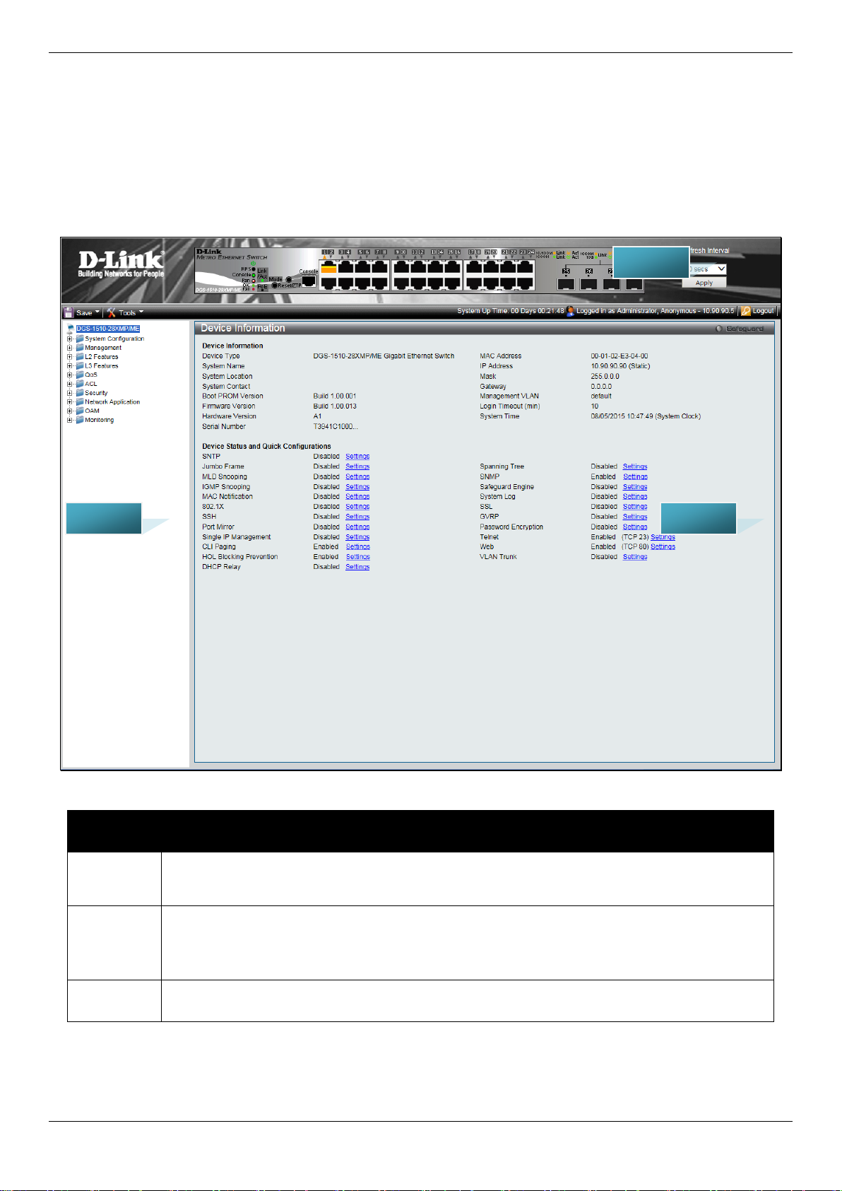
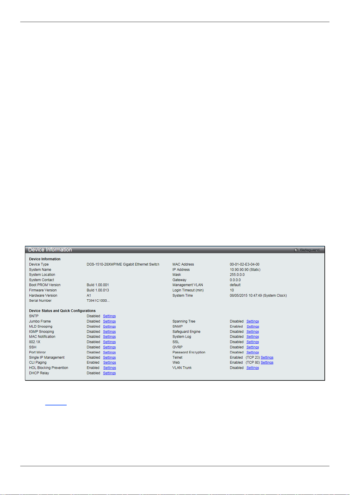
Device Information
This window contains the main settings for al l the major functions for the Switch. It appears automatically when you
log on to the Switch. To return to the Device Informat ion window after viewing other windows, click the DGS-1510/ME
Series link.
The Device Information window shows the Switch’s MAC Address (assigned by the factory and un changeable), the
Boot PROM Version, Firmware Version, Hard ware Version, and many other important types of i nformation. This is
helpful to keep track of PROM and firmware updates and to obtain the Switch’s MAC address f or entry into another
network device’s address table, if necessary. In addition, this window displays the status of f unctions on the Switch to
quickly assess their current global status .
Many functions are hyper-linked for easy access to enable quick configuration from this window.
Figure 2-1 Device Information windo w
Click the Settings link to navigate to the appropriate feature page for configuration.
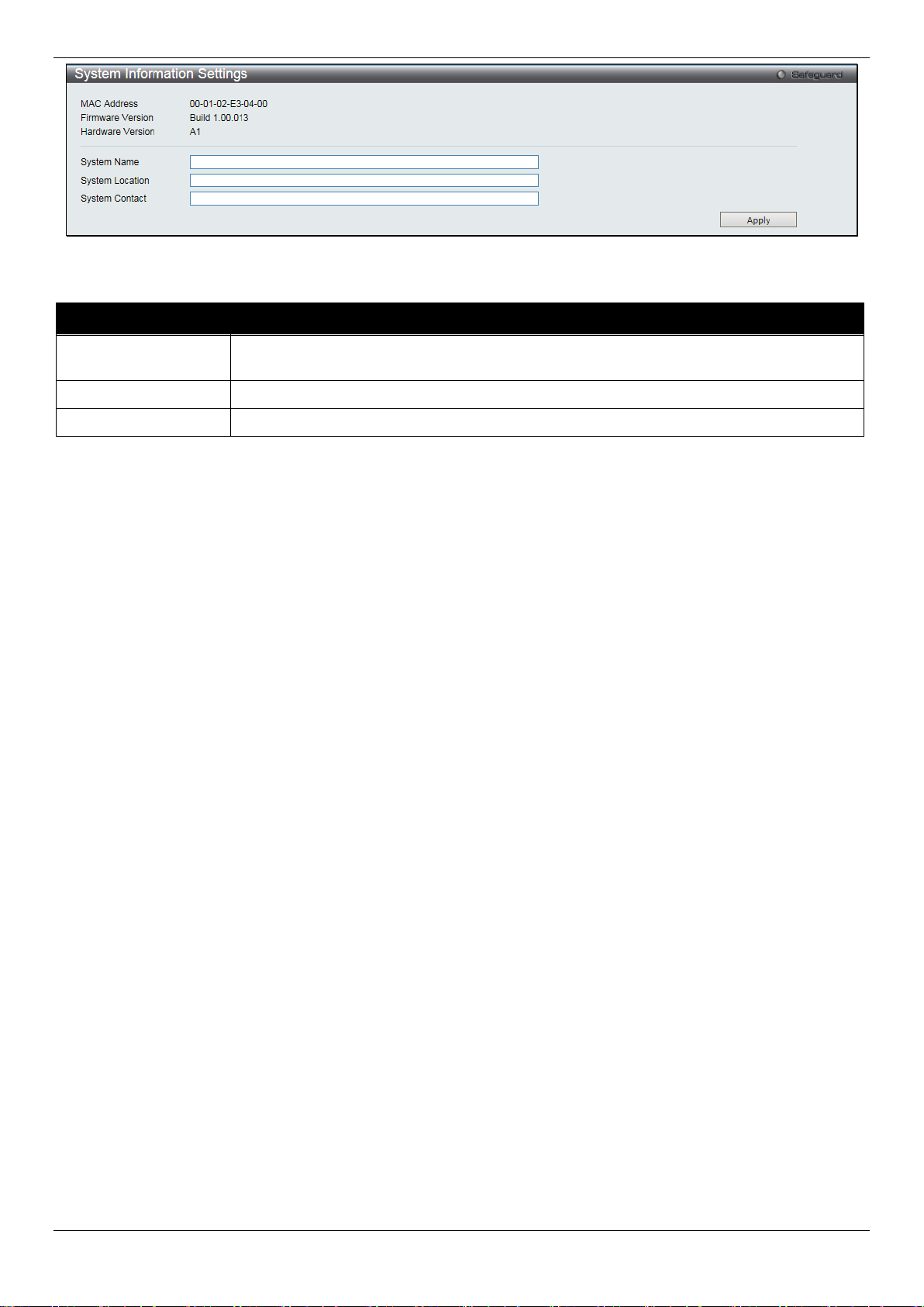
System Information Settings
The user can enter a System Name, System Location, and System Contact to aid in defining the Switch.
To view the following window, click System Configuration > System Information Settings, as show below:
8
Page 17
DGS-1510/ME Series Metro Ethernet Switch Web UI Reference Guide
network.
System Location
Enter the location of the Switch, if so desired.
System Contact
Enter a contact name for the Switch, if so desired.
Figure 2-2 System Information Settings window
The fields that can be configured are described below:
Parameter Description
System Name
Click the Apply button to implement changes made.
Enter a system name for the Switch, if so desired. This name will identify it in the Switch
Port Configuration
DDM
This folder contains windows that perform Digital Diagnostic Monitoring (DDM) functions on the Switch. There are
windows that allow the user to view the digital diagnostic monitoring status of SFP modules inserting to the Switch and
to configure alarm settings, warning settings, temperature threshold settings, voltage t hreshold settings, bias current
threshold settings, Tx power threshold settings, and Rx power threshold settings.
DDM Settings
The window is used to configure the action that will occur for specific ports when an exceeding alarm threshold or
warning threshold event is encountered.
To view the following window, click System Configuration > Port Configuration > DDM > DDM Settings, as show
below:
9
Page 18

DGS-1510/ME Series Metro Ethernet Switch Web UI Reference Guide
warning threshold.
warning threshold.
From Port / To Port
Select a range of ports to be configured.
State
Use the drop-down menu to enable or disable the DDM state.
not. This is the default.
Figure 2-3 DDM Settings window
The fields that can be configured are described below:
Parameter Description
Trap State
Log State
Shutdown
Click the Apply button to accept the changes made for each individual section.
Specify whether to send the trap, when the operating parameter exceeds the alarm or
Specify whether to send the log, when the operati ng parameter exceeds the alarm or
Specify whether to shutdown the port, when t he operating parameter exceeds the Alarm or
Warning threshold.
Alarm - Shutdown the port when the configured alarm thres hol d range is exceeded.
Warning - Shutdown the port when the configure d warning threshold range is exceeded.
None - The port will never shutdown regardless if the threshold ranges are exceeded or
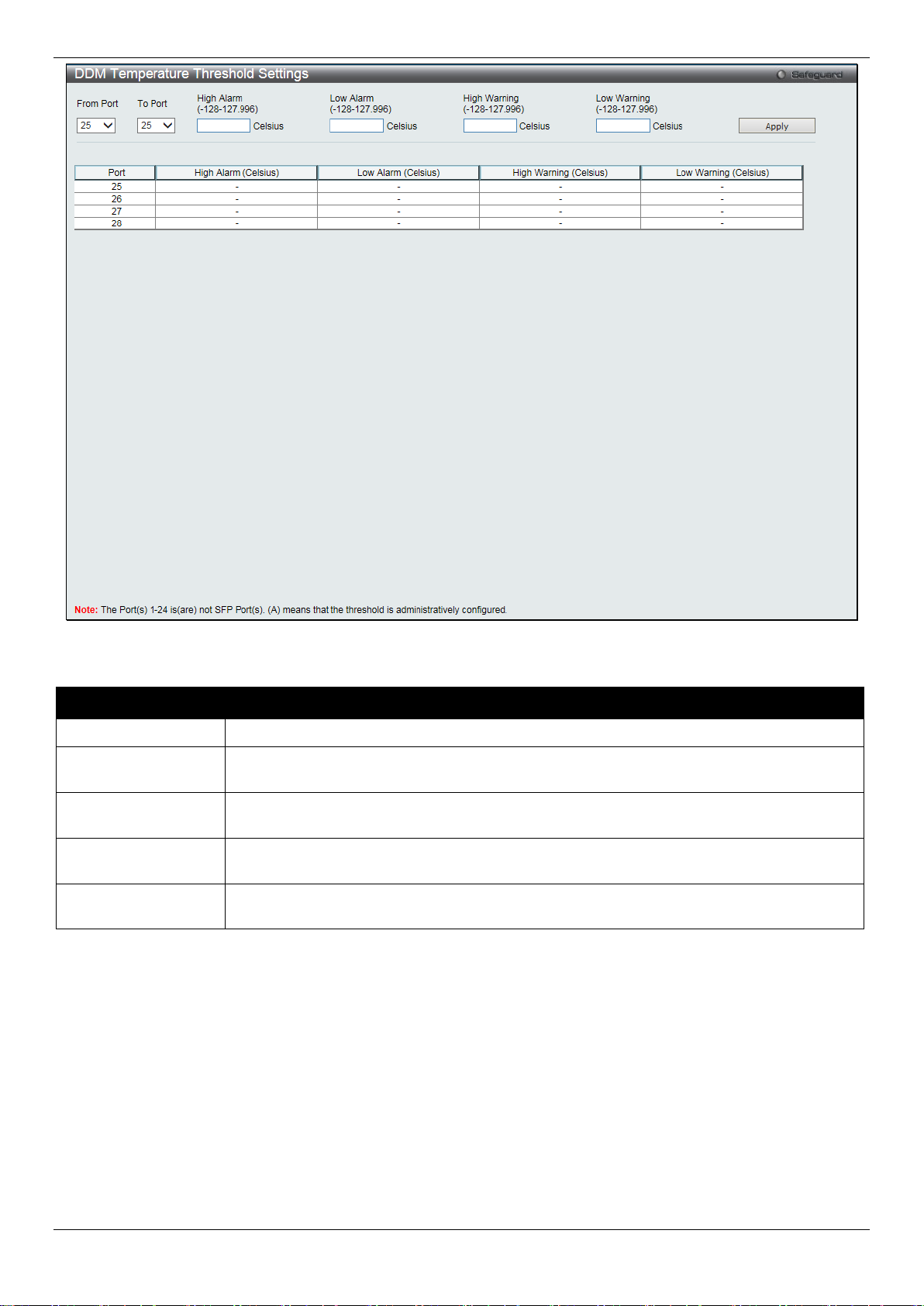
DDM Temperature Threshold Se tti ng s
This window is used to configure the DDM Temperature Threshold Settings for specific ports on the Switch.
To view the following window, click System Configuration > Port Configuration > DDM > DDM Temperature
Threshold Settings, as show below:
10
Page 19
DGS-1510/ME Series Metro Ethernet Switch Web UI Reference Guide
From Port / To Port
Select a range of ports to be configured.
127.996)
value, action associated with the alarm wil l be taken.
127.996)
value, action associated with the alarm wil l be taken.
127.996)
this value, action associated with the warning will be taken.
127.996)
value, action associated with the warnin g wil l be taken.
Figure 2-4 DDM Temperature Threshold Settings window
The fields that can be configured are described below:
Parameter Description
High Alarm (-128-
Low Alarm (-128-
High Warning (-128-
Low Warning (-128-
Click the Apply button to accept the changes made.
This is the highest threshold for the alarm. When the operating parameter rises above this
This is the lowest threshold for the alarm. When the operating parameter falls below this
This is the highest threshold for the warning. Wh en the operating parameter rises above
This is the lowest threshold for the warning. Whe n the operating parameter falls below this
DDM Voltage Threshold Settings
This window is used to configure the DDM Voltage Threshold Settings for specific ports on the Switch.
To view the following window, click System Configuration > Port Configuration > DDM > DDM Voltage Threshold
Settings, as show below:
11
Page 20

DGS-1510/ME Series Metro Ethernet Switch Web UI Reference Guide
From Port / To Port
Select a range of ports to be configured.
value, action associated with the alarm wil l be taken.
value, action associated with the alarm wil l be taken.
6.55)
this value, action associated with the warning will be taken.
6.55)
value, action associated with the warnin g wil l be taken.
Figure 2-5 DDM Voltage Threshold Settings window
The fields that can be configured are described below:
Parameter Description
High Alarm (0-6.55)
Low Alarm (0-6.55)
High Warning (0-
Low Warning (0-
Click the Apply button to accept the changes made.
This is the highest threshold for the alarm. When the operating parameter rises above this
This is the lowest threshold for the alarm. When the operating parameter falls below this
This is the highest threshold for the warning. Wh en the operating parameter rises above
This is the lowest threshold for the warning. Whe n the operating parameter falls below this
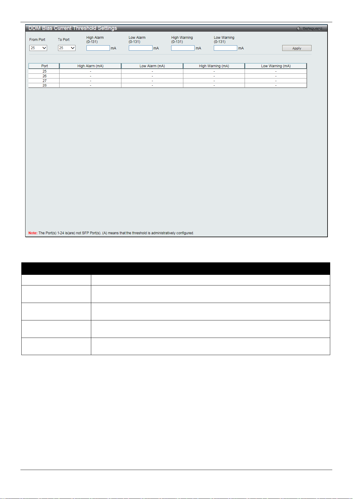
DDM Bias Current Thres hold Settings
This window is used to configure the threshold of the bias current for specific ports on the Switch.
To view the following window, click System Configuration > Port Configuration > DDM > DDM Bias Current
Threshold Settings, as show below:
12
Page 21
DGS-1510/ME Series Metro Ethernet Switch Web UI Reference Guide
From Port / To Port
Select a range of ports to be configured.
this value, action associated with the alarm will be taken.
value, action associated with the alarm will be taken.
this value, action associated with the warning will be taken.
this value, action associated with the warning will be taken.
Figure 2-6 DDM Bias Current Threshold Settings window
The fields that can be configured are described below:
Parameter Description
High Alarm (0-131)
Low Alarm (0-131)
High Warning (0-131)
Low Warning (0-131)
Click the Apply button to accept the changes made.
This is the highest threshold for the alarm. When the operating parameter rises above
This is the lowest threshold for the alarm. When the operating parameter falls below this
This is the highest threshold for the warning. Wh en the operating parameter rises above
This is the lowest threshold for the warning. When the operating parameter falls below
DDM TX Power Threshold Settings
This window is used to configure the threshold of Tx power for specific ports on the Switch.
To view the following window, click System Configuration > Port Configuration > DDM > DDM TX Power
Threshold Settings, as show below:
13
Page 22

DGS-1510/ME Series Metro Ethernet Switch Web UI Reference Guide
From Port / To Port
Select a range of ports to be configured.
6.5535)
value, action associated with the alarm wil l be taken.
6.5535)
value, action associated with the alarm wil l be taken.
6.5535)
this value, action associated with the warning will be taken.
6.5535)
value, action associated with the warnin g wil l be taken.
Figure 2-7 DDM TX Power Threshold Settings window
The fields that can be configured are described below:
Parameter Description
High Alarm (0-
Low Alarm (0-
High Warning (0-
Low Warning (0-
Click the Apply button to accept the changes made.
This is the highest threshold for the alarm. When the operating parameter rises above this
This is the lowest threshold for the alarm. When the operating parameter falls below this
This is the highest threshold for the warning. Wh en the operating parameter rises above
This is the lowest threshold for the warning. Whe n the operating parameter falls below this
DDM RX Power Threshold Settings
This window is used to configure the threshold of RX power for specific ports on the Switch.
To view the following window, click System Configuration > Port Configuration > DDM > DDM RX Power
Threshold Settings, as show below:
14
Page 23

DGS-1510/ME Series Metro Ethernet Switch Web UI Reference Guide
From Port / To Port
Select a range of ports to be configured.
6.5535)
value, action associated with the alarm will be taken.
6.5535)
value, action associated with the alarm wil l be taken.
6.5535)
this value, action associated with the warning will be taken.
6.5535)
value, action associated with the warning will be tak en.
Figure 2-8 DDM RX Power Threshold Settings window
The fields that can be configured are described bel ow:
Parameter Description
High Alarm (0-
Low Alarm (0-
High Warning (0-
Low Warning (0-
Click the Apply button to accept the changes made.
This is the highest threshold for the alarm. When the operating parameter rises above this
This is the lowest threshold for the alarm. When the operating parameter falls below this
This is the highest threshold for the warning. Wh en the operating parameter rises above
This is the lowest threshold for the warning. Whe n the operating parameter falls below this
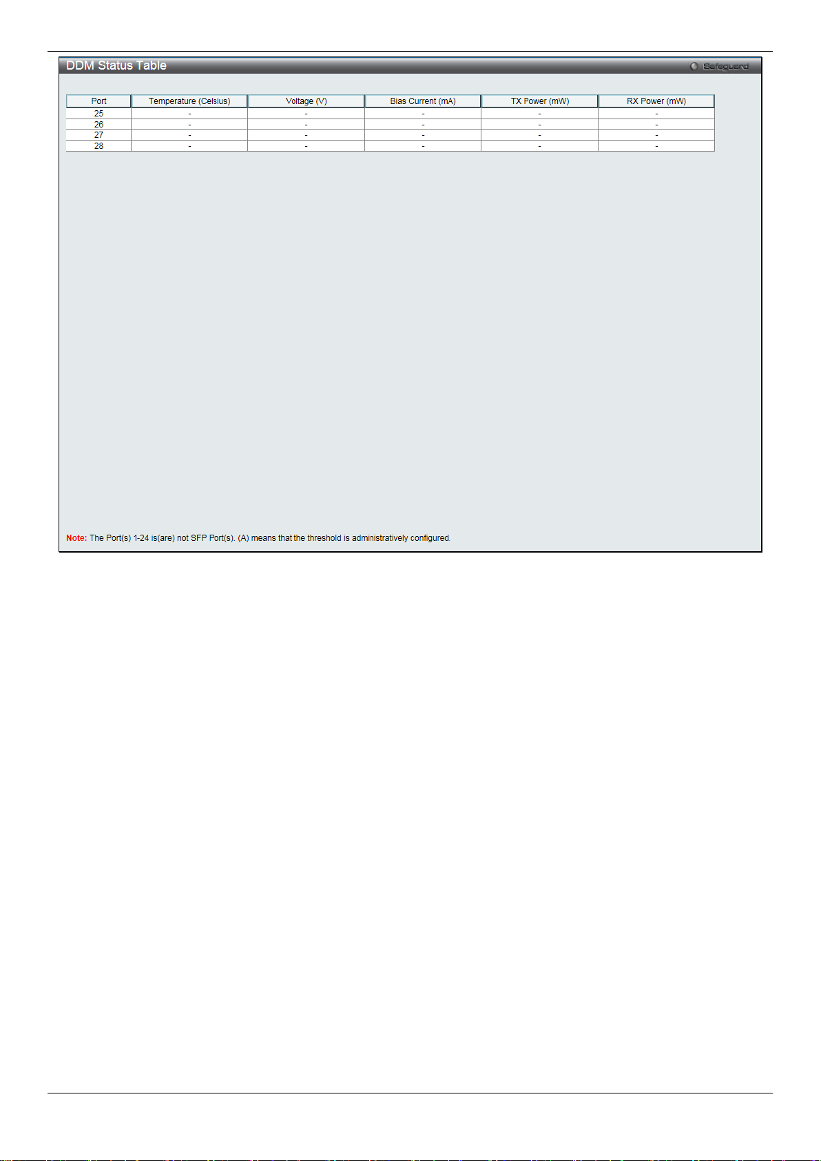
DDM Status Table
This window is used to display the current operating digital diagnostic monitoring parameters and their values on the
SFP module for specified ports.
To view the following window, click System Configuration > Port Configuration > DDM > DDM Status Table, as
show below:
15
Page 24
DGS-1510/ME Series Metro Ethernet Switch Web UI Reference Guide
Figure 2-9 DDM Status Table window
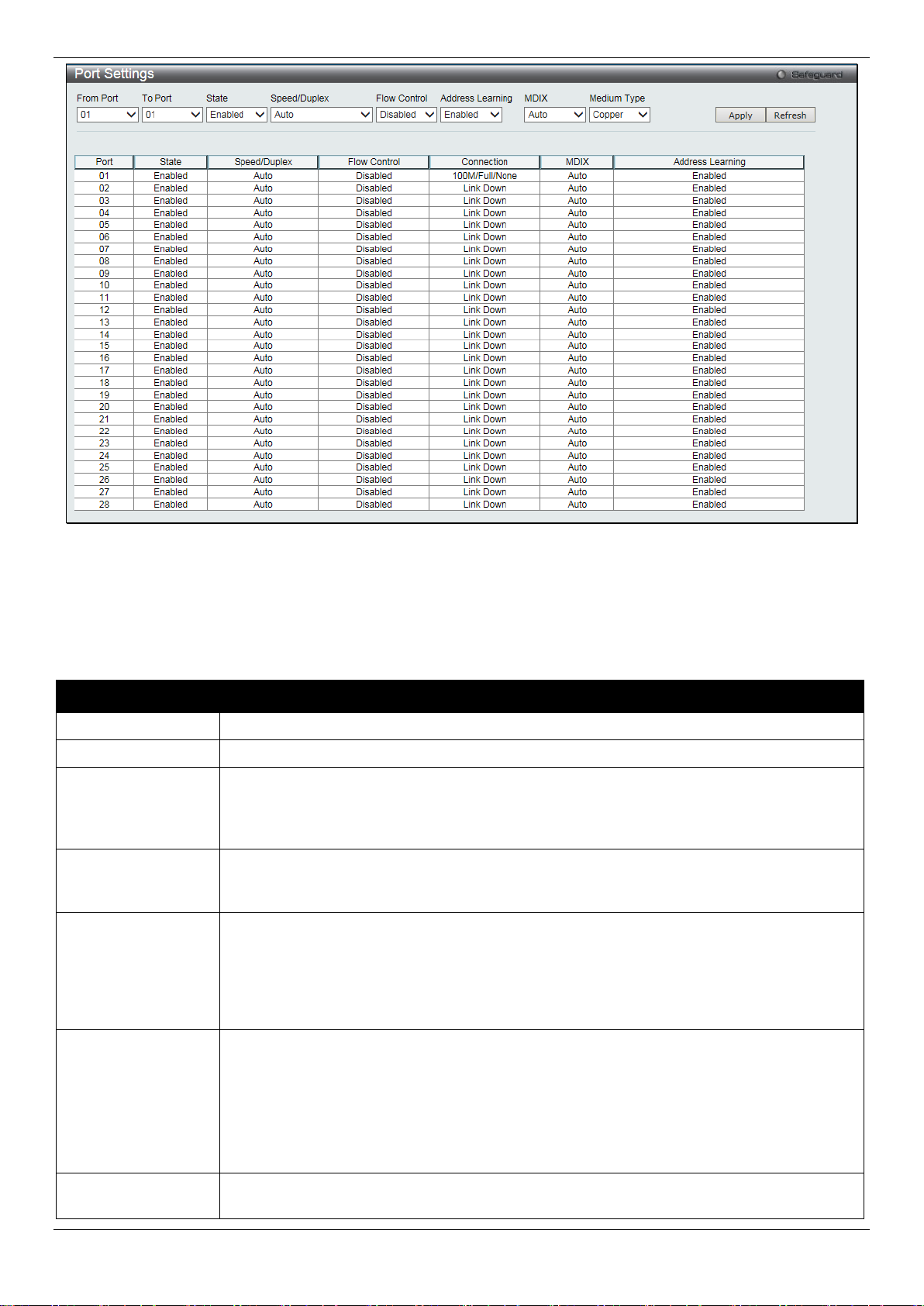
Port Settings
This page used to configure the details of the swit ch ports.
To view the following window, click System Configuration > Port Configuration > Port Settings, as show below:
16
Page 25
DGS-1510/ME Series Metro Ethernet Switch Web UI Reference Guide
From Port / To Port
Select the appropriate port range used for the configuration here.
State
Toggle the State field to either enable or di sable a given port or group of ports.
available options are Auto, 100M Full, 1000M Full, and 10G Ful l.
Auto ports use an automatic selection of the two. The default is Disabled.
The default setting is Enabled.
cable.
Fiber.
Figure 2-10 Port Settings window
To configure switch ports:
1. Choose the port or sequential range of ports using the From Port and To Port drop-down menus.
2. Use the remaining drop-down menus to configure the parameters described below:
The fields that can be configured are described below:
Parameter Description
Speed/Duplex
Select the speed and full-duplex/half-duplex st ate of the port. When Copper is selected in
Medium Type, the available options are Auto, 10M Half, 10M Full, 100M Half, 100M F ul l,
1000M Full_Master, and 1000M Full_Slave. When Fiber is selected in Medium Type, the
Flow Control
Displays the flow control scheme used for the various port configurations. Ports configur ed
for full-duplex use 802.3x flow control, half-duplex ports use b ackpressure flow control, and
Address Learning
Enable or disable MAC address learning for the selected ports. When Enabled, destination
and source MAC addresses are automatically l i st ed i n the forwarding table. When address
learning is Disabled, MAC addresses must be m anually entered into the forwarding table.
This is sometimes done for reasons of security or efficiency. See the section on
Forwarding/Filtering for information on en tering MAC addresses into the forwarding table.
MDIX
Auto - Select auto for auto sensing of the optimal t ype of cabling.
Normal - Select normal for normal cabling. If this option is selected, the port is in the MDIX
mode and can be connected to a PC’s NIC using a straight-through cable or a port (in the
MDIX mode) on another switch through a cross-over cable.
Cross - Select cross for cross cabling. If this option is selected, the port is in MDI mode,
and can be connected to a port (in the MDIX mode) on anoth er switch through a straight
Medium Type
Select the type of transport medium to be used. Opt i ons to choose from are Copper and
17
Page 26
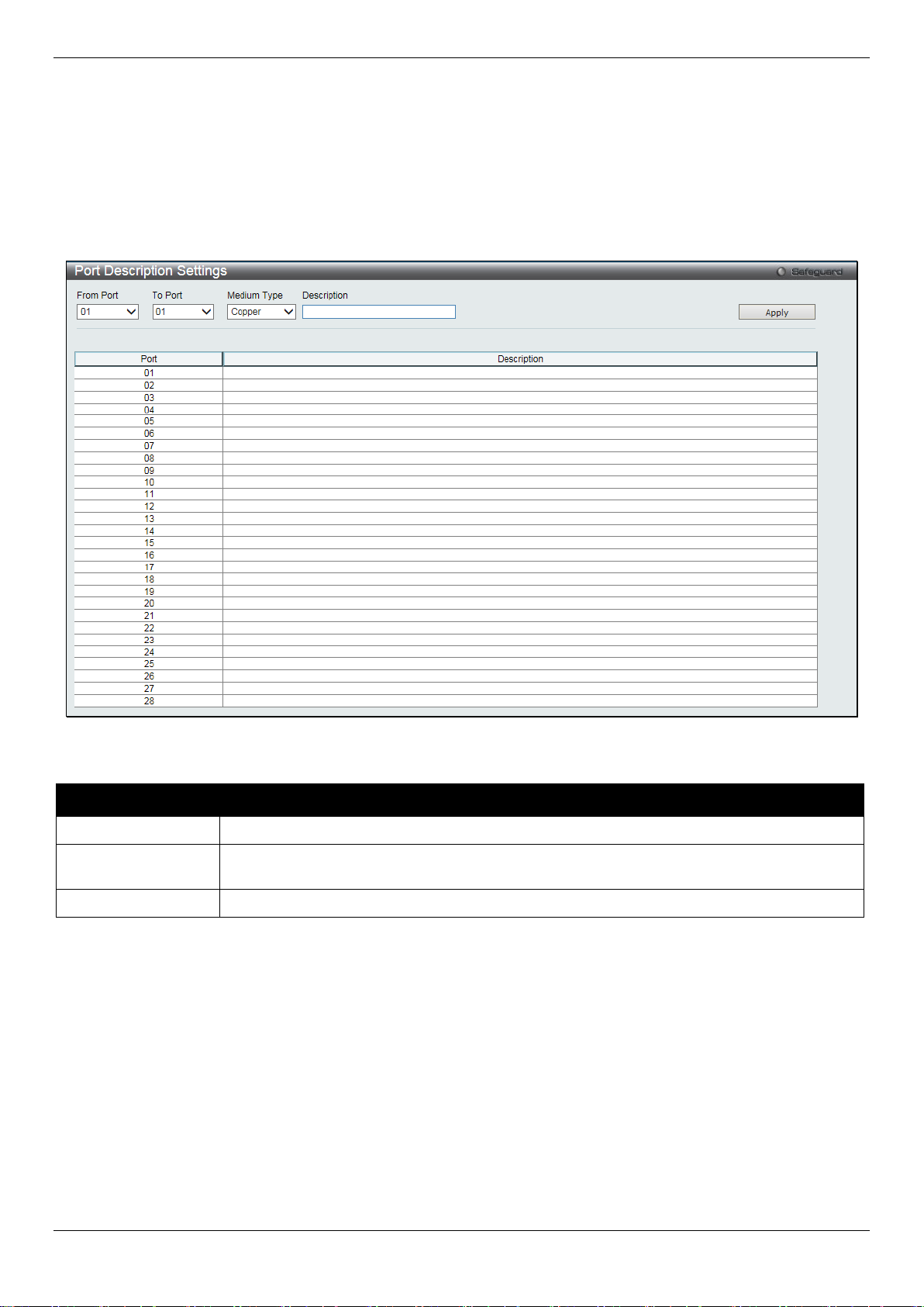
DGS-1510/ME Series Metro Ethernet Switch Web UI Reference Guide
From Port / To Port
Select the appropriate port range used for the configuration here.
Type defines the type of transport medium to be used, whether Copper or Fiber.
Description
Users may then enter a description for the chos en port(s).
Click the Apply button to implement changes made.
Click the Refresh button to refresh the display section of this page.
Port Description Settings
The Switch supports a port description feat ure where the user may name various ports.
To view the following window, click System Configuration > Port Configuration > Port Description Settings, as
show below:
Figure 2-11 Port Description Settings window
The fields that can be configured are described below:
Parameter Description
Medium Type
Click the Apply button to implement changes made.
Specify the medium type for the selected ports. If conf iguring the Combo ports, the Medium
Port Error Disabled
The following window displays the information about ports that have been disconnected by the Switch when a packet
storm occurs or a loop was detected.
To view the following window, click System Configuration > Port Configuration > Port Error Disabled, as show
below:
18
Page 27

DGS-1510/ME Series Metro Ethernet Switch Web UI Reference Guide
Port
Display the port that has been error disabled.
Port State
Describe the current running state of the port, whet her enabled or disabled.
Connection Status
Display the uplink status of the individual ports, whether enabled or disabled.
shutdown port for storm control.
enabled, the maximum frame size is 9,216 bytes.
Figure 2-12 Port Error Disabled
The fields that can be displayed are described below:
Parameter Description
Reason
Describe the reason why the port has been error-dis abl ed, such as it has become a
Jumbo Frame Settings
The Switch supports jumbo frames. Jumbo f rames are Ethernet frames with more than 1,536 bytes of payload. The
Switch supports jumbo frames with a maximum frame size of up to 9,216 bytes.
To view the following window, click System Configuration > Port Configuration > Jumbo Frame Settings, as show
below:
Figure 2-13 Jumbo Frame Settings window
The fields that can be configured are described below:
Parameter Description
Jumbo Frame
Use the radio buttons to enable or disable the Jumbo Frame function on the Switch. The
default is Disabled. When disabled, the max im um frame size is 1,536 bytes. When
Click the Apply button to implement changes made.
EEE Settings
Energy Efficient Ethernet (EEE) is defined in I EEE 802.3az. It is designed to reduce the energy consumption of a link
when no packets are being sent. EEE and ERPS are mutually exclusive functions.
To view the following window, click System Configuration > Port Configuration > EEE Settings, as shown below:
19
Page 28
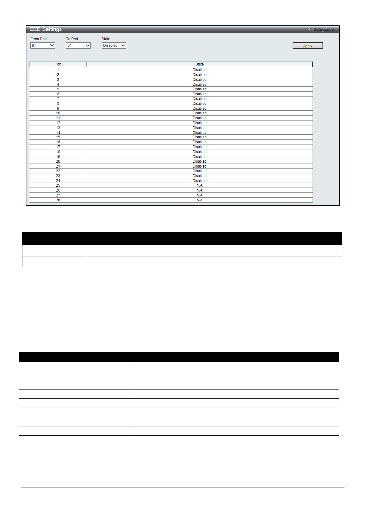
DGS-1510/ME Series Metro Ethernet Switch Web UI Reference Guide
From Port / To Port
Select the appropriate port range used for the configuration here.
State
Select to enable or disable the state of this feature here.
Pin
Alternative
1
Negative Vport
2
Negative Vport
3
Positive Vport
4 5 6
Positive Vport
7 8
Figure 2-14 EEE Settings window
The fields that can be configured are described below:
Parameter Description
Click the Apply button to implement changes made.
PoE
The DGS-1510-28LP/ME and DGS-1510-28XMP/ME switches support Power over Ethernet (PoE) as defined by the
IEEE 802.3af and 802.3at standard. Ports 1 t o 24 for DGS-1510-28LP/ME and DGS-1510-28XMP/ME can supply
about 48 VDC power to Powered Devices (PDs) over Category 5 or Category 3 UTP Ethernet cables.
The Switch follows the standard Power Sourcing Eq ui pment (PSE) pinout Alternative A, whereby power is sent out
over pins 1, 2, 3 and 6. The Switches work with all D-Link 802.3af capable devices.
The Switch includes the following PoE features:
• Auto-discovery recognizes the connection of a Powered Device (PD) and automatically sends power t o i t.
• The Auto-disable function will activate when the port current value exceeds 350mA or when a short happens.
20
Page 29

DGS-1510/ME Series Metro Ethernet Switch Web UI Reference Guide
Class
Usage
Minimum output power levels of PSE devices
0
Default
15.4 Watt
1
Optional
4.0 Watt
2
Optional
7.0 Watt
3
Optional
15.4 Watt
4
Reserved
Treat as Class 0
Class
Usage
Minimum output power levels of PSE devices
0
Default
15.4 Watt
1
Optional
4.0 Watt
2
Optional
7.0 Watt
3
Optional
15.4 Watt
4
Optional
15.4 or 30 Watt
Type 2 = 30 Watt.
For 802.3af capable devices, evaluate the t able below, containing the correct power level per class and their
respective usage options.
For 802.3at capable devices, evaluate the t able below, containing the correct power level per class and their
respective usage options. This feature prov i des power allocation of 0.1 Watt granularity, using the LLDP method.
NOTE: Class 4 devices use the following equatio n:
Ptype=Icable x V Port_PSE min
Type 1 = 15.4 Watt.
To configure the PoE features on the Switch, click System Configuration > PoE.
PoE System Settings
This window is used to assign a power limit and power disconnect method for the whole PoE system. When the total
consumed power exceeds the power limit configured in this window, the PoE controller (located in the PSE)
disconnects the power to prevent overloading t he power supply.
To view the following window, click System Configuration > PoE > PoE System Settings, as show below:
21
Page 30
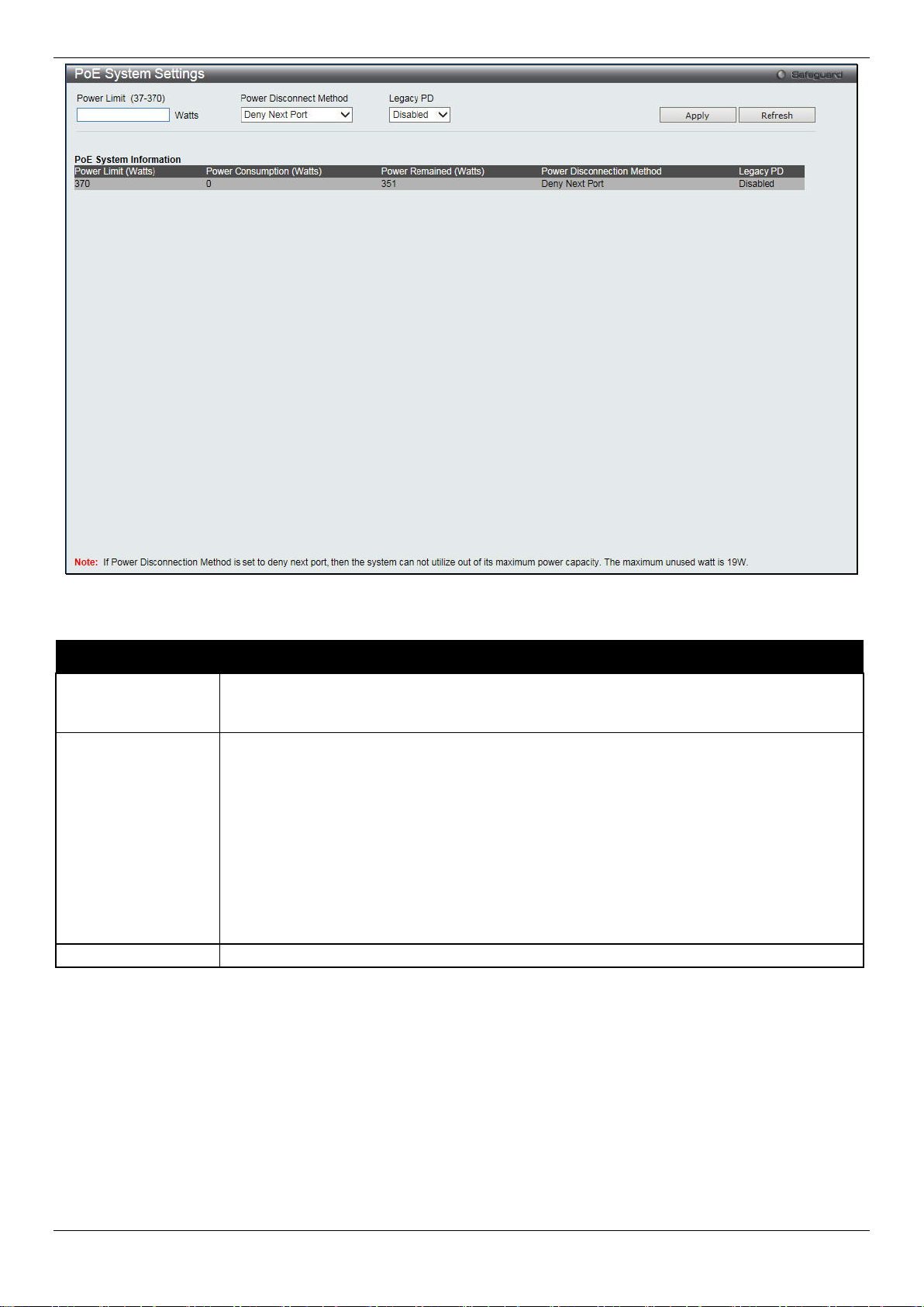
DGS-1510/ME Series Metro Ethernet Switch Web UI Reference Guide
between 37W and 370W for DGS-1510-28XMP/ME.
priority and critical priority ports to power up.
Legacy PD
Use the drop-down menu to enable or disable detecting legacy PDs signal.
Figure 2-15 PoE System Settings window
The following parameters can be configured:
Parameter Description
Power Limit
Power Disconnect
Method
Click Apply to implement changes made.
Sets the limit of power to be used from the Switch’ s power source to PoE ports. The user
may configure a Power Limit between 37W and 193W for DGS-1510-28LP/ME, and
The PoE controller uses either Deny Next Port or Deny Low Priority Port to offset t he power
limit being exceeded and keeps the Switch’s power at a usable level. Use the drop down
menu to select a Power Disconnect Method. The default P ower Disconnect Method is
Deny Next Port. Both Power Disconnection Met hods are described below:
Deny Next Port – After the power limit has been exceeded, the next port attempting to
power up is denied, regardless of its priority. If Power Disconnection Method is set to Deny
Next Port, the system cannot utilize out of its maximum power capacity. The maximum
unused watt is 10W for DGS-1510-28LP/ME and 19W for DGS-1510-28XMP/ME.
Deny Low Priority Port – After the power limit has been exceeded, the next port attempting
to power up causes the port with the lowest priorit y to shut down so as to allow the high-
PoE Port Settings
To view the following window, click System Configuration > PoE > PoE Port Settings, as show below:
22
Page 31

DGS-1510/ME Series Metro Ethernet Switch Web UI Reference Guide
From Port / To Port
Select a range of ports from the drop-down menus to be enabled or disabled for PoE.
State
Use the drop-down menu to enable or disable ports for PoE.
can only be supplied during the specified perio d of time.
be used by the system to manage the supply of power to ports.
into account any power loss on the cable. Thus, the following are the typical values:
Figure 2-16 PoE Port Settings window
The following parameters can be configured:
Parameter Description
Time Range
Priority
Power Limit
Select a range of the time to the port set as POE. If Time Range is configured, the power
Use the drop-down menu to select the priority of the PoE ports. Port priority determines the
priority which the system attempts to supply the power to the ports. There are three levels
of priority that can be selected, Critical, High, and Low. When multiple ports happen to have
the same level of priority, the port ID will be used to det erm ine the priority. The lower port
ID has higher priority. The setting of priority will affect the order of supplying power.
Whether the disconnect method is set to deny low priority port, the priority of each port will
This function is used to configure the per-port power limit. If a port exceeds its power limit, it
will shut down.
For 802.3af capable devices, the minimum output power levels of PSE devices for each
class is:
Class 0 – 15.4 Watt
Class 1 – 4.0 Watt
Class 2 – 7.0 Watt
Class 3 – 15.4 Watt
Class 4 – Treat as Class 0
For 802.3at capable devices with power allocation of 0.1 Watt granularity, using the LLDP
method, the minimum output power level s of P SE devices for each class is:
Class 0 – 15.4 Watt
Class 1 – 4.0 Watt
Class 2 – 7.0 Watt
Class 3 – 15.4 Watt
Class 4 – 15.4 or 30 Watt
The following is the power limit applied to the port for these five classes. For each class,
the power limit is a little more than the power consumption range for that class. Thi s takes
23
Page 32

DGS-1510/ME Series Metro Ethernet Switch Web UI Reference Guide
User Define – 1000 to 35000mW
2. Manually configure the corresponding port’s power limit value to 30 Watts.
console port, the baud rate must be set to 115200, which is the default setting.
Never. The default setting is 10 minutes.
Data Bits
Display the data bits used for the serial port connection.
Parity Bits
Display the parity bits used for the serial port connection.
Stop Bits
Display the stop bits used for the serial port connection.
Class 0 – 16200mW
Class 1 – 4200mW
Class 2 – 7400mW
Class 3 – 16200mW
Click Apply to implement changes made. The port status of all PoE configured ports is displayed in the table in the
bottom half of the screen shown above.
NOTE: If the switch fails to supply power to the Powered Device (PD) that suppo rt s the IEEE 802.3at
standard,
1. Check if the PD connected to the port support s the IEEE 802.3at standard.
Serial Port Settings
This window allows the user to adjust the Baud Rat e and the Auto Logout values.
To view the following window, click System Configuration > Serial Port Settings, as show below:
Figure 2-17 Serial Port Settings window
The fields that can be configured or displayed are described below:
Parameter Description
Baud Rate
Auto Logout
Click the Apply button to implement changes made.
Specify the baud rate for the serial port on the Swit ch. There are four possible baud rates to
choose from, 9600, 19200, 38400 and 115200. For a connection to the Switch using the
Select the logout time used for the console interface. This automatically logs the user out after
an idle period of time, as defined. Choose from the f ollowing options: 2, 5, 10, 15 minutes or
Warning Temperature Settings
This window allows the user to configure the syst em warning temperature parameters.
To view the following window, click System Configuration > Warning Temperature Settings, as show below:
24
Page 33

DGS-1510/ME Series Metro Ethernet Switch Web UI Reference Guide
temperature setting.
temperature setting.
High Threshold (-500-500)
Enter the high threshold value of the warning temperature setting.
Low Threshold (-500-500)
Enter the low threshold value of the warning temperature setting.
System Log
Use the radio buttons to enable or disable the sy st em log settings.
every time a log event occurs on the Switch.
Figure 2-18 Warning Temperature Settings window
The fields that can be configured are described below:
Parameter Description
Traps State
Log State
Click the Apply button to implement changes made.
Use the drop-down menu to enable or disable the traps state option of the warning
Use the drop-down menu to enable or disable the log state option of the warning
System Log Configuration
System Log Settings
The Switch allows users to choose a method for whi ch to save the switch log to the flash memory of the Switch.
To view the following window, click System Configuration > System Log Configuration > System Log Settings,
as show below:
Figure 2-19 System Log Settings window
The fields that can be configured are described below:
Parameter Description
Save Mode
Click the Apply button to accept the changes made for each individual section.
Use the drop-down menu to choose the method for saving the switch log to the flash
memory. The user has three options:
On Demand – Users who choose this method will o nl y save log files when they manually
tell the Switch to do so, either using the Save Log link in the Save folder.
Time Interval – Users who choose this method can configure a time interval by which the
Switch will save the log files, in the box adjacent to this configuration field. The user may
set a time between 1 and 65535 minutes.
Log Trigger – Users who choose this method will have log files saved to the Switch
25
Page 34

DGS-1510/ME Series Metro Ethernet Switch Web UI Reference Guide
Server ID
Syslog server settings index (1 to 4).
Emergency, Alert, Critical, Error, Warning, Notice, Informational and Debug.
Server IPv4 Address
The IPv4 address of the Syslog server.
Local 6, or Local 7.
6000-65535)
Status
Choose Enabled or Disabled to activate or deactivate.
System Log Server Settings
The Switch can send System log messages to up to f our designated servers using the System Log Server.
To view the following window, click System Configuration > System Log Configuration > System Log Server
Settings, as show below:
Figure 2-20 System Log Server Settings
The fields that can be configured are described below:
Parameter Description
Severity
Facility
UDP Port (514 or
Click the Apply button to accept the changes made.
Click the Edit button to re-configure the specific entry.
Click the Delete button to remove the specific entry.
Click the Delete All button to remove all servers configured.
Use the drop-down menu to select the higher level of messages that will be sent. All
messages which level is higher than selecting level will be sent. The options are
Use the drop-down menu to select Local 0, Local 1, L ocal 2, Local 3, Local 4, Local 5,
Type the UDP port number used for sending Syslog m essages. The default is 514.
System Log
Users can view and delete the local history log as compiled by the Switch's management agent.
To view the following window, click System Configuration > System Log Configuration > System Log, as show
below:
Figure 2-21 System Log window
26
Page 35

DGS-1510/ME Series Metro Ethernet Switch Web UI Reference Guide
Attack Log - When selecting Attack Log all attacks will be listed.
displays the last entry (highest sequenc e num ber) first.
Time
Display the time in days, hours, minutes, and seconds.
Level
Display the level of the log entry.
Log Text
Display text describing the event that t ri ggered the history log entry.
Interface Name
Enter the IP interface name used.
IPv4 Address
Enter the IPv4 address used.
The fields that can be configured or displayed are described below:
Parameter Description
Log Type
Index
Click the Find button to display the log in the display section according to the se l ect i on m ade.
Click the Clear Log button to clear the entries from the log in the display section.
Click the Clear Attack Log button to clear the entries f rom the attack log in the display section.
The Switch can record event information in i ts own log. Click Go to go to the next page of the System Log window.
In the drop-down menu the user can select the log t ype that will be displayed.
Severity - When selecting Severity from the drop-down menu, a secondary tick must be
made. Secondary ticks are Emergency, Alert, Critical, E rror, Warning, Notice ,
Informational and Debug. To view all information in the log, simply tick the All chec k box .
Module List - When selecting Module List, the module name must be manually entered.
Available modules are MSTP, ERROR_LOG and ERPS.
A counter incremented whenever an entry t o the Switch's history log is made. The table
System Log & Trap Settings
The Switch allows users to configure the system log source IP interface addresses here.
To view the following window, click System Configuration > System Log Configuration > System Log & Trap
Settings, as show below:
Figure 2-22 System Log & Trap Settings window
The fields that can be configured are described below:
Parameter Description
Click the Apply button to accept the changes made for each individual section.
Click the Clear button to clear all the information entered in the fields.
System Severity Settings
The Switch can be configured to allow alerts be lo gged or sent as a trap to an SNMP agent. The level at which the
alert triggers either a log entry or a trap message can be set as well. Use the System Severity Settings window to set
the criteria for alerts. The current settings are displayed below the System Severity Table.
To view the following window, click System Configuration > System Log Configuration > System Severity
Settings, as show below:
27
Page 36

DGS-1510/ME Series Metro Ethernet Switch Web UI Reference Guide
Switch’s log for analysis.
Debug (7).
to identify the access profile and associated rule to be enabled during this time range.
minutes and seconds, based on the 24-hour time syst em.
Weekdays
Use the check boxes to select the corresponding days of the week that this time range
Figure 2-23 System Severity Settings window
The fields that can be configured are described below:
Parameter Description
System Severity
Severity Level
Click the Apply button to accept the changes made.
Choose how the alerts are used from the drop-down menu. Select Log to send t he al ert of the
Severity Type configured to the Switch’s log for anal ysis. Choose Trap to send it to an SNMP
agent for analysis, or select All to send the chosen alert type to an SNMP agent and the
This drop-down menu allows you to select the level of messages that will be sent. The options
are Emergency (0), Alert (1), Critical (2), Error (3), Warnin g (4), Notice (5), Information (6) and
Time Range Settings
Time range is a time period that the respective functi on will take an effect on, such as ACL. For example, t he
administrator can configure the time-based ACL to al low users to surf the Internet on every Saturday and every
Sunday, meanwhile to deny users to surf the Internet on weekdays.
The user may enter up to 64 time range entries on the Switch.
To view the following window, click System Configuration > Time Range Settings, as show below:
Figure 2-24 Time Range Settings window
The fields that can be configured are described below:
Parameter Description
Range Name
Hours (HH MM SS)
Enter a name of no more than 32 alphanumeric charact ers that will be used to identify
this time range on the Switch. This range name will be used in the Access Profile table
This parameter is used to set the time in the day that this time range is to be enabled
using the following parameters:
Start Time - Use this parameter to identify the starting time of the time range, in hours,
minutes and seconds, based on the 24-hour time syst em.
End Time - Use this parameter to identify t he endi ng time of the time range, in hours,
28
Page 37

DGS-1510/ME Series Metro Ethernet Switch Web UI Reference Guide
is to be enabled. Tick the Select All Days check b ox to configure this time range for
every day of the week.
Date (DD / MM / YYYY)
Enter the current day, month, and year to update the system clock.
Time (HH:MM:SS)
Enter the current time in hours, minutes, and seconds.
Management
Admin
Operator
Power User
User
partly
partly
Network Monitoring
Read/Write
Read/Write
Read-only
Read-only
Stations
Click the Apply button to accept the changes made.
Click the Delete button to remove the specific entry.
Enter a page number and click the Go button to navigate to a specific page when multiple pages exist.
Time Settings
Users can configure the time settings for the Swit ch.
To view the following window, click System Configuration > Time Settings, as show below:
Figure 2-25 Time Settings window
The fields that can be configured are described below:
Parameter Description
Click the Apply button to accept the changes made.
User Accounts Settings
The Switch allows the control of user privileges.
To view the following window, click System Configuration > User Accounts Settings, as show below:
Figure 2-26 User Accounts Settings window
To add a new user, type in a User Name and New Password and retype the same password i n the Confirm New
Password field. Choose the level of privilege (Admin, Operator, Power User or User) from the Access Right drop-down
menu.
Configuration Read/Write Read/Write–
Community Strings and Trap
Read/Write Read-only Read-only Read-only
29
Read/Write–
No
Page 38
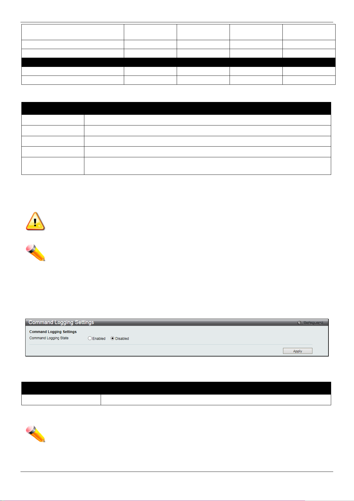
DGS-1510/ME Series Metro Ethernet Switch Web UI Reference Guide
Files
System Utilities
Read/Write
Read-only
Read-only
Read-only
Factory Reset
Read/Write
No
No
No
User Account Management
Add/Update/Delete User Accounts
Read/Write
No
No
No
View User Accounts
Read/Write
No
No
No
User Name
Enter a new user name for the Switch.
Password
Enter a new password for the Switch.
Confirm Password
Re-type in a new password for the Switch.
Access Right
Specify the access right for this user.
Text, and SHA-1.
Command Logging State
Use the radio buttons to enable or disable the f unct i on.
used the Enable Admin function to replace its privilege.
Update Firmware and Configuration
The fields that can be configured are described below:
Parameter Description
Encryption
Click the Apply button to accept the changes made.
Click the Edit button to re-configure the specific entry.
Click the Delete button to remove the specific entry.
Specifies that encryption will be applied to t his account. Option to choose from are Plain
Read/Write Read/Write No No
NOTICE: In case of lost passwords or password corruption, please refer to Appendix A Password
Recovery Procedure which will guide you throug h the steps necessary to resolve this issue.
NOTE: The username and password should be less than 16 characters.
Command Logging Settings
This window is used to enable or disable the comm and logging settings.
To view this window, click System Configuration > Command Logging Settings, as shown below:
Figure 2-27 Command Logging Settings window
The fields that can be configured are described below:
Parameter Description
Click the Apply button to accept the changes made.
NOTE: When the Switch is under the booting procedure, all configuration com m ands will not be logged.
When the user uses AAA authentication to log in, the username should not be changed if the user has
30
Page 39

DGS-1510/ME Series Metro Ethernet Switch Web UI Reference Guide
ARP Aging Time (0-65535)
The ARP entry age-out time, in minutes. The default is 20 minutes.
IP Address
The IP address of the ARP entry.
MAC Address
The MAC address of the ARP entry.
Chapter 3 Management
ARP
Gratuitous ARP
IPv6 Neighbor Settings
IP Interface
Management Settings
Session Table
Single IP Management
SNMP Settings
Telnet Settings
Web Settings
ARP
Static ARP Settings
The Address Resolution Protocol is a TCP/IP protocol that converts IP addresses int o physical addresses. This table
allows network managers to view, define, m odify, and delete ARP information for specific devices. Static entries can
be defined in the ARP table. When static entries are defined, a permanent entry is entered and is used to translate IP
addresses to MAC addresses.
To view the following window, click Management > ARP > Static ARP Settings, as show below:
Figure 3-1 Static ARP Settings window
The fields that can be configured are described below:
Parameter Description
Click the Apply button to accept the changes made for each individual section.
Click the Delete All button to remove all the entries listed.
Click the Edit button to re-configure the specific entry.
Click the Delete button to remove the specific entry.
ARP Table
Users can display current ARP entries on the Switch.
To view the following window, click Management > ARP > ARP Table, as show below:
31
Page 40

DGS-1510/ME Series Metro Ethernet Switch Web UI Reference Guide
Interface Name
Enter or view the Interface name used.
IP Address
Enter or view the IP Address used.
MAC Address
Enter or view the MAC Address used.
packet will be broadcast.
gratuitous ARP request packets for this duplicate IP address.
Figure 3-2 ARP Table window
The fields that can be configured are described below:
Parameter Description
Click the Find button to locate a specific entry based on the inf ormation entered.
Click the Show Static button to display only the static entries in the display table.
Click the Clear All button to remove all the entries listed in the table.
Enter a page number and click the Go button to navigate to a specific page when multiple pages exist.
Gratuitous ARP
Gratuitous ARP Global Settings
The user can enable or disable the gratuitous A RP gl obal settings here.
To view the following window, click Management > Gratuitous A RP > Gratuitous ARP Global Settings, as show
below:
Figure 3-3 Gratuitous ARP Global Settings Window
The fields that can be configured are described below:
Parameter Description
Send On IP Interface
Status Up
The command is used to enable/disable sending of gratuitous ARP request packet while
the IPIF interface become up. This is used to automatically announce the interface’s IP
address to other nodes. By default, the state is Enabled, and only one gratuitous ARP
Send On Duplicate IP
Detected
The command is used to enable/disable the sendi ng of gratuitous ARP request packet
while a duplicate IP is detected. By default, t he st ate is Enabled. For this command, the
duplicate IP detected means that the system rec ei ved an ARP request packet that is
sent by an IP address that match the system’s own IP address. In this case, the system
knows that somebody out there uses an IP address t hat is conflict with the system. In
order to reclaim the correct host of this IP address, the system can send out the
32
Page 41

DGS-1510/ME Series Metro Ethernet Switch Web UI Reference Guide
Enabled.
disabled.
log is enabled.
gratuitous ARP trap or log on all interfaces.
gratuitous ARP request will not be sent periodi cally. By default the interval time is 0.
Gratuitous ARP
Learning
Click the Apply button to accept the changes made.
NOTE: With the gratuitous ARP learning, the system will not learn new entry but onl y do the update on
the ARP table based on the received gratuitous ARP packet.
Normally, the system will only learn the ARP repl y packet or a normal ARP request
packet that asks for the MAC address that corresponds to the system’s IP address. The
command is used to enable/disable learning of A RP entry in ARP cache based on the
received gratuitous ARP packet. The gratuit ous A RP packet is sent by a source IP
address that is identical to the IP that the packet is queries for. By default, the state is
Gratuitous ARP Settings
The user can configure the IP interface’s gratuitous ARP parameter.
To view the following window, click Management > Gratuit ous ARP > Gratuitous ARP Settings, as show below:
Figure 3-4 Gratuitous ARP Settings window
The fields that can be configured are described below:
Parameter Description
Trap
Log
Interface Name
Interval Time (0-65535)
Click the Apply button to accept the changes made for each individual section.
Use the drop-down menu to enable or disable the trap option. By default the trap is
Use the drop-down menu to enable or disable the logging option. By default the event
Enter the interface name of the Layer 3 interface. Select All to enable or disable
Enter the periodically send gratuitous ARP int erval time in seconds. 0 means that
IPv6 Neighbor Settings
The user can configure the Switch’s IPv6 neighb or settings. The Switch’s current IPv6 neighbo r settings will be
displayed in the table at the bottom of this window.
To view the following window, click Management > IPv 6 Neighbor Settings, as show below:
33
Page 42

DGS-1510/ME Series Metro Ethernet Switch Web UI Reference Guide
Interface Name
Enter the interface name of the IPv6 neighbor.
Neighbor IPv6 Address
Enter the neighbor IPv6 address.
Link Layer MAC Address
Enter the link layer MAC address.
interfaces on the Switch.
address in the space provided next to the stat e option.
Figure 3-5 IPv6 Neighbor Settings window
The fields that can be configured are described below:
Parameter Description
Interface Name
State
Click the Add button to add a new entry based on the information ent ered.
Click the Find button to locate a specific entry based on the inf ormation entered.
Click the Clear button to clear all the information entered in the fields.
Enter a page number and click the Go button to navigate to a specific page when multiple pages exist.
Enter the name of the IPv6 neighbor. Tick the All check b ox to search for all current
Use the drop-down menu to select All, Address, S tatic, or Dynamic. When the user
selects address from the drop-down menu, the user will be able to enter an IP
IP Interface
System IP Address Settings
The IP address may initially be set using the console interface prior to connecting to it through t he Ethernet. The Web
manager will display the Switch’s current IP settings.
NOTE: The Switch’s factory default IP address is 10.90.90.90 with a subnet mask of 255.0.0.0 and a
default gateway of 0.0.0.0.
34
Page 43

DGS-1510/ME Series Metro Ethernet Switch Web UI Reference Guide
address on the network assigned for use by t he network administrator.
it with this information before using the def ault or previously entered settings.
entered settings.
Interface Name
Display the System interface name.
are assigned.
state is disabled, the IP interface cannot be ac cessed.
IP Address
This field allows the entry of an IPv4 address to be assigned to this IP interface.
are allowed.
to be accessible outside your local network, you can l eave this field unchanged.
To view the following window, click Management > IP Interface > System IP Address Settings, as show below:
Figure 3-6 System IP Address Settings window
The fields that can be configured are described below:
Parameter
Description
Static
Allow the entry of an IP address, subnet mask, and a default gateway for the Switch.
These fields should be of the form xxx.xxx. xx x.xxx, where each xxx is a number
(represented in decimal form) between 0 and 255. This address should be a unique
DHCP
The Switch will send out a DHCP broadcast request when it is powered up. The DHCP
protocol allows IP addresses, network masks, and default gateways to be assigned by a
DHCP server. If this option is set, the Switch wil l first look for a DHCP server to provide
BOOTP
The Switch will send out a BOOTP broadcast req uest when it is powered up. The
BOOTP protocol allows IP addresses, network masks, and default gateways to be
assigned by a central BOOTP server. If this option is set, the Switch will first look for a
BOOTP server to provide it with this information b efore using the default or previously
The following table will describe the field s that are about the System Interface.
Parameter Description
Management VLAN
Name
This allows the entry of a VLAN name from which a m anagement station will be allowed
to manage the Switch using TCP/IP (in-band via Web manager or Telnet). Management
stations that are on VLANs other than the one entered here will not be able to manage
the Switch in-band unless their IP addresses are entered in the Trusted Host window
(Security > Trusted Host). If VLANs have not yet been confi gured for the Switch, the
default VLAN contains all of the Switch’s ports. There are no entries in the Trusted Host
table, by default, so any management station t hat can connect to the Switch can access
the Switch until a management VLAN is specified or Management Station IP addresses
Interface Admin State
Subnet Mask
Use the drop-down menu to enable or disable the configuration on this interface. If the
A Bitmask that determines the extent of the subnet that the Switch is on. Should be of
the form xxx.xxx.xxx.xxx, where each xxx is a number (represented in decimal) between
0 and 255. The value should be 255.0.0.0 for a Class A network, 255.255.0.0 for a
Class B network, and 255.255.255.0 for a Class C network, but custom subnet masks
Gateway
IP address that determines where packets wit h a destination address outside the
current subnet should be sent. This is usually the address of a router or a host acting as
an IP gateway. If your network is not part of an intranet, or you do not want the Switch
35
Page 44

DGS-1510/ME Series Metro Ethernet Switch Web UI Reference Guide
Interface Name
Enter the name of the IP interface to search for.
Interface Name
Enter the name of the IP interface being created.
IPv4 Address
Enter the IPv4 address used.
Subnet Mask
Enter the IPv4 subnet mask used.
VLAN Name
Enter the VLAN Name used.
Interface Admin State
Use the drop-down menu to enable or disable the I nterface Admin State.
Click the Apply button to accept the changes made.
Interface Settings
Users can display the Switch’s current IP interface settings.
To view the following window, click Management > IP Interface > Interface Settings, as show below:
Figure 3-7 Interface Settings window
The fields that can be configured are described below:
Parameter Description
Click the Find button to locate a specific entry based on the inf ormation entered.
Click the Add button to add a new entry based on the information ent ered.
Click the Delete All button to remove all the entries listed.
Click the IPv4 Edit button to edit the IPv4 settings for the specific entry.
Click the IPv6 Edit button to edit the IPv6 settings for the specific entry.
Click the Delete button to remove the specific entry.
NOTE: To create IPv6 interfaces, the user has to create an IPv4 interfac e then edit it to IPv6.
Click the Add button to see the following window.
Figure 3-8 IPv4 Interface Settings window
The fields that can be configured are described below:
Parameter Description
Click the Apply button to accept the changes made.
Click the <<Back button to discard the changes made and return to t he previous page.
36
Page 45

DGS-1510/ME Series Metro Ethernet Switch Web UI Reference Guide
address.
Interface Name
Enter the name of the IP interface being configured.
IPv4 Address
Enter the IPv4 address used.
Subnet Mask
Enter the IPv4 subnet mask used.
VLAN Name
Enter the VLAN Name used.
IPv4 State
Use the drop-down menu to enable or disable IPv4 State.
Interface Admin State
Use the drop-down menu to enable or disable the I nterface Admin State.
DHCPDISCOVER and DHCPREQ UE ST message.
Name
message.
Interface Name
Display the IPv6 interface name.
IPv6 State
Use the drop-down menu to enable or disable IPv6 State.
Click the IPv4 Edit button to see the following window.
Figure 3-9 IPv4 Interface Settings – Edit window
The fields that can be configured are described below:
Parameter Description
Get IP From
DHCP Option 12 State
DHCP Option 12 Host
Use the drop-down menu to specify the method that this Interface uses to acquire an IP
Use the drop-down menu to enable or disable insertion of option 12 in the
Enter the host name to be inserted in the DHCPDIS COVER and DHCPREQUEST
Click the Apply button to accept the changes made.
Click the <<Back button to discard the changes made and return to t he previous page.
Click the IPv6 Edit button to see the following window.
Figure 3-10 IPv6 Interface Settings window
The fields that can be configured or displayed are described below:
Parameter Description
37
Page 46

DGS-1510/ME Series Metro Ethernet Switch Web UI Reference Guide
Interface Admin State
Use the drop-down menu to enable or disable the I nterface Admin State.
IPv6 Network Address
Here the user can enter the IPv6 global or local lin k address.
configured, it will duplicate the entry into the RA field.
Address
NS Retransmit Time (0-
4294967295)
Automatic Link Local
Click the Apply button to accept the changes made for each individual section.
Click the <<Back button to discard the changes made and return to t he previous page.
Click the View All IPv6 Address link to view all the current IPv6 address.
Click the View All IPv6 Address link to see the following window.
Click the <<Back button to return to the previous page.
Enter the Neighbor solicitation’s retransmit timer in millisecond here. It has the same
value as the RA retransmit time in the config ipv6 nd ra command. If this field is
Here the user can select to enable or disable the Automatic Link Local Address.
Figure 3-11 IPv6 Interface Settings window
Management Settings
Users can stop the scrolling of multiple pages beyond the limits of the console when using the Command Line
Interface.
This window is also used to enable the DHCP auto conf iguration feature on the Switch. When enabled, the Switch is
instructed to receive a configuration file from a TF TP server, which will set the Switch to become a DHCP c li ent
automatically on boot-up. To employ this met hod, the DHCP server must be set up to deliver the TFTP se rver IP
address and configuration file name information in the DHCP reply packet. The TFTP server must be up and running
and hold the necessary configuration file stored in i ts base directory when the request is received from the Switch. For
more information about loading a configuration f i l e for use by a client, see the DHCP server and/or TFTP server
software instructions. The user may also con sult the Upload Log File window description located in the Tools section
of this manual.
If the Switch is unable to complete the DHCP aut o configuration, the previously saved configuration file present in the
Switch’s memory will be used.
Users can also configure Password Encryption on the Switch.
To view the following window, click Management > Management Settings, as show below:
Figure 3-12 Management Settings window
38
Page 47

DGS-1510/ME Series Metro Ethernet Switch Web UI Reference Guide
Paging is Enabled by default. To disable it, click t he Disabled radio button.
request is received from the Switch.
(1-65535)
Enabled radio button.
running configuration.
The fields that can be configured are described below:
Parameter Description
CLI Paging State
DHCP Auto
Configuration State
Autoconfig Timeout
Password Encryption
State
Running
Configuration
Click the Apply button to accept the changes made.
To learn more about the D-Link Green Technologies, go to http://green.dlink.com/
Command Line Interface paging stops each p age at the end of the console. This allows
you to stop the scrolling of multiple pages of tex t beyond the limits of the console. CLI
Enable or disable the Switch’s DHCP auto configuration feature. When enabled, the
Switch is instructed to receive a configuration file from a TFTP server, which will set the
Switch to become a DHCP client automatically on boot-up. To employ this method, the
DHCP server must be set up to deliver the TFTP server IP address and configuration
file name information in the DHCP reply packet . The TFTP server must be up and
running and hold the necessary configuration file stored in its base directory when the
Enter a time between 1 and 65535 for the auto-configurati on timeout.
Password encryption will encrypt the passwo rd configuration in configuration files.
Password encryption is Disabled by default. To enable password encryption, click the
Under the Password Recovery option, the run ning configuration can be enabled or
disable. Being enabled, will allow the user t o perf orm a password recovery of the
for more details.
Session Table
Users can display the management sessions si nce the Switch was last rebooted.
To view the following window, click Management > Session Table, as show below:
Figure 3-13 Session Table window
Click the Refresh button to refresh the display table so that new entries will appear.
Single IP Management
D-Link Single IP Management is a concept that wil l st ack switches together over Ethernet instead of using stacking
ports or modules. There are some advantages in implementing the “Single IP Management” feature:
• SIM can simplify management of small workgroups or wiring closets while scaling the network to handle
increased bandwidth demand.
• SIM can reduce the number of IP address needed i n your network.
• SIM can eliminate any specialized cables for stacking connectivity and remove the distance barriers that
typically limit your topology options when using ot her stacking technology.
Switches using D-Link Single IP Management (labeled here as SIM) must conform to the following rule s:
1. SIM is an optional feature on the Switch and can easily be enabled or disabled through the Command Line
Interface or Web Interface. SIM grouping has no effect on the normal operation of the Swit ch in the user’s
network.
39
Page 48

DGS-1510/ME Series Metro Ethernet Switch Web UI Reference Guide
2. There are three classifications for switches using SIM. The Commander Switch (CS), which is the master
switch of the group, Member Switch (MS), whic h i s a switch that is recognized by the CS a member of a SIM
group, and a Candidate Switch (CaS), which is a S witch that has a physical link to the SIM group but has not
been recognized by the CS as a member of the SIM group.
3. A SIM group can only have one Commander Switch (CS).
4. A SIM group accepts up to 32 switches (numbere d 1-32), not including the Commander Switch (numbered 0).
5. Members of a SIM group cannot cross a router.
6. There is no limit to the number of SIM groups in the same IP subnet (broadcast domain); however a single
switch can only belong to one group.
7. If multiple VLANs are configured, the SI M group will only utilize the default VLAN on any switch.
8. SIM allows intermediate devices that do not sup port SIM. This enables the user to manage switches that are
more than one hop away from the CS.
The SIM group is a group of switches that are managed as a single entity. The Switch may take on three different
roles:
a. Commander Switch (CS) – This is a switch that has been manually configured as the controlling
device for a group, and takes on the following characteristics:
a. It has an IP Address.
b. It is not a command switch or member switch of another Single IP group.
c. It is connected to the member switches through its management VLAN.
b. Member Switch (MS) – This is a switch that has joined a single IP group and is accessible from the
CS, and it takes on the following characterist ics:
a. It is not a CS or MS of another IP group.
b. It is connected to the CS through the CS managem ent VLAN.
c. Candidate Switch (CaS) – This is a switch that is ready to join a SIM group but is not yet a member
of the SIM group. The Candidate Switch may j oin the SIM group of the Switch by manually configurin g
it to be a MS of a SIM group. A switch configured as a CaS is not a member of a SIM group and will
take on the following characteristics:
• It is not a CS or MS of another Single IP group.
• It is connected to the CS through the CS managem ent VLAN
The following rules also apply to the above roles:
1. Each device begins in a Candidate state.
2. CSs must change their role to CaS and then to MS, to become a MS of a SIM group. Thus, the CS canno t
directly be converted to a MS.
3. The user can manually configure a CS to become a CaS.
4. A MS can become a CaS by:
• Being configured as a CaS through the CS.
• If report packets from the CS to the MS time out.
5. The user can manually configure a CaS to become a CS
6. The CaS can be configured through the CS to become a MS.
After configuring one switch to operate as the CS of a SIM group, additional DGS-1510/ME Series switches may join
the group by manually configuring the Switch to be a MS. The CS will then serve as the in band entry point for access
to the MS. The CS’s IP address will become t he path to all MS’s of the group and the CS’s Administrator’s password,
and/or authentication will control access to all M S ’ s of the SIM group.
With SIM enabled, the applications in the CS will redirect the packet instead of executing the packets. The
applications will decode the packet from the adm i ni strator, modify some data, and then send it to the MS. After
execution, the CS may receive a response pac ket from the MS, which it will encode and send it back to the
administrator.
When a CaS becomes a MS, it automatically becomes a member of the first SNMP community (includes read/write
and read only) to which the CS belongs. However, if a MS has its own IP address, it can belong to SNMP
communities to which other switches in the group, including the CS, do not belong.
40
Page 49
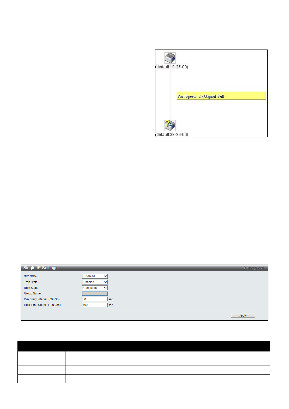
DGS-1510/ME Series Metro Ethernet Switch Web UI Reference Guide
will render all SIM functions on the Switch inoperable.
Trap State
Use the drop-down menu to enable or disable sending the trap.
Role State
Use the drop-down menu to change the SIM role of the Switch. The two choices are:
Upgrade to v1.61
To better improve SIM management, the DGS-1510/ME Series switches have been upgraded to version 1.61 in this
release. Many improvements have been made, including:
a. The Commander Switch (CS) now has the capability
to automatically rediscover member switches t hat
have left the SIM group, either through a reboot or
web malfunction. This feature is accomplishe d
through the use of Discover packets and
Maintenance packets that previously set SI M
members will emit after a reboot. Once a MS has had
its MAC address and password saved to the CS’s
database, if a reboot occurs in the MS, the CS will
keep this MS information in its database and w hen a
MS has been rediscovered, it will add the MS back
into the SIM tree automatically. No configuration will
be necessary to rediscover these switches.
There are some instances where pre-saved MS switches
cannot be rediscovered. For example, if t he S witch is still
powered down, if it has become the member of another group,
or if it has been configured to be a Commander Switch, the
rediscovery process cannot occur.
b. The topology map now includes new features for connections that are a member of a port trunking group. It
will display the speed and number of Ethernet connections creating this port trunk group, as shown in the
adjacent picture.
c. This version will support switch upload and downloads for firmware, configuration files and log files, as follows:
• Firmware – The switch now supports MS firmware downloads from a TFTP server.
• Configuration Files – This switch now supports downloading and uploading of configuration files both to
(for configuration restoration) and from (for configuration backup) MS’s, using a TFTP server.
• Log – The Switch now supports uploading MS l og files to a TFTP server.
d. The user may zoom in and zoom out when utilizing the t opol ogy window to get a better, more defined view of
the configurations.
Single IP Settings
The Switch is set as a Candidate (CaS) as the factory default configuration and Single IP Management is disabled.
To view the following window, click Management > Single IP Management > Single IP Settings, as show below:
Figure 3-14 Single IP Settings window
The fields that can be configured are described below:
Parameter Description
SIM State
Use the drop-down menu to either enable or disable the S IM state on the Switch. Disabled
41
Page 50

DGS-1510/ME Series Metro Ethernet Switch Web UI Reference Guide
Choosing this option will also enable the Swit ch to be configured for SIM.
SIM groups.
from 30 to 90 seconds. The default value is 30 seconds.
to 255 seconds. The default value is 100 seconds.
Candidate – A Candidate Switch (CaS) is not the member of a SIM group but is connected to
a Commander Switch. This is the default set ting for the SIM role of the Switch.
Commander – Choosing this parameter will m ake t he Switch a Commander Switch (CS).
The user may join other switches to this Switch, ov er Ethernet, to be part of its SIM group.
Group Name
Discovery Interval
(30-90)
Hold Time Count
(100-255)
Click the Apply button to accept the changes made.
After enabling the Switch to be a Commande r S witch (CS), the Single IP Management folder will then contain four
added links to aid the user in configuring SIM t hrough the web, including Topology, Firmware Upgrade,
Configuration Backup/Restore and Upload Log File.
Enter a Group Name in this textbox. This is optional, and only available when SIM State is
Enabled and Role State is Candidate. This name is used to segment switches into different
The user may set the discovery protocol interv al , in seconds that the Switch will send out
discovery packets. Returning informatio n to a Commander Switch will include information
about other switches connected to it. (Ex. MS, CaS). The user may set the Discovery Interval
This parameter may be set for the time, in seconds; t he Switch will hold information sent to it
from other switches, utilizing the Discovery Interval. The user may set the hold time from 100
Topology
This window will be used to configure and manage the Switch within the SIM group and requires Java script to
function properly on your computer.
The Java Runtime Environment on your server should initiate and lead you to the Topology window, as s een below.
42
Page 51
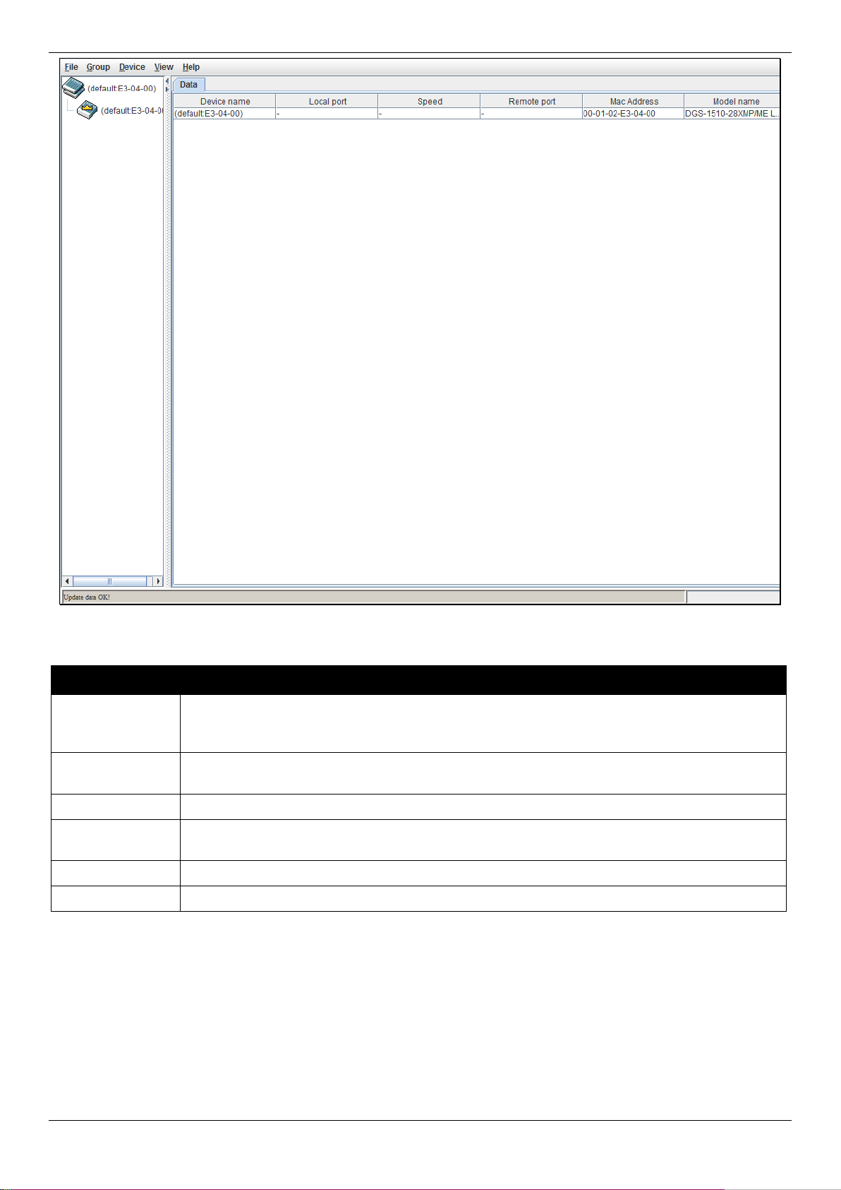
DGS-1510/ME Series Metro Ethernet Switch Web UI Reference Guide
the last six digits of the MAC Address to identify it.
CS will have no entry in this field.
Speed
Displays the connection speed between the CS and the MS or CaS.
CS will have no entry in this field.
MAC Address
Displays the MAC Address of the corresponding S witch.
Model Name
Displays the full Model Name of the correspon di ng Switch.
Figure 3-15 Single IP Management window - Tree View
The Topology window holds the following inf orm ation on the Data tab:
Parameter Description
Device Name
This field will display the Device Name of t he swit ches in the SIM group configured by the
user. If no device is configured by the name, it wil l be gi ven the name default and tagged with
Local Port
Remote Port
Displays the number of the physical port on the CS that the MS or CaS is connected to. The
Displays the number of the physical port on the MS or CaS to which the CS is connected. The
To view the Topology View window, open the View drop-down menu in the toolbar and then click Topology, which
will open the following Topology Map. This window will refresh itself periodically (20 seconds by default).
43
Page 52

DGS-1510/ME Series Metro Ethernet Switch Web UI Reference Guide
Figure 3-16 Topology view
This window will display how the devices within the Single IP Management Group connect to ot her groups and
devices. Possible icons on this window are as foll ows:
Icon Description Icon Description
Group
Layer 2 commander switch
Layer 3 commander switch
Commander switch of other group
Layer 2 member switch.
Layer 3 member switch
Member switch of other group
Layer 2 candidate switch
Layer 3 candidate switch
Unknown device
Non-SIM devices
Tool Tips
In the Topology view window, the mouse plays an important role in configuration and in viewing device information.
Setting the mouse cursor over a specific device in t he topology window (tool tip) will display the same inf ormation
about a specific device as the Tree view does. See the window below for an example.
44
Page 53
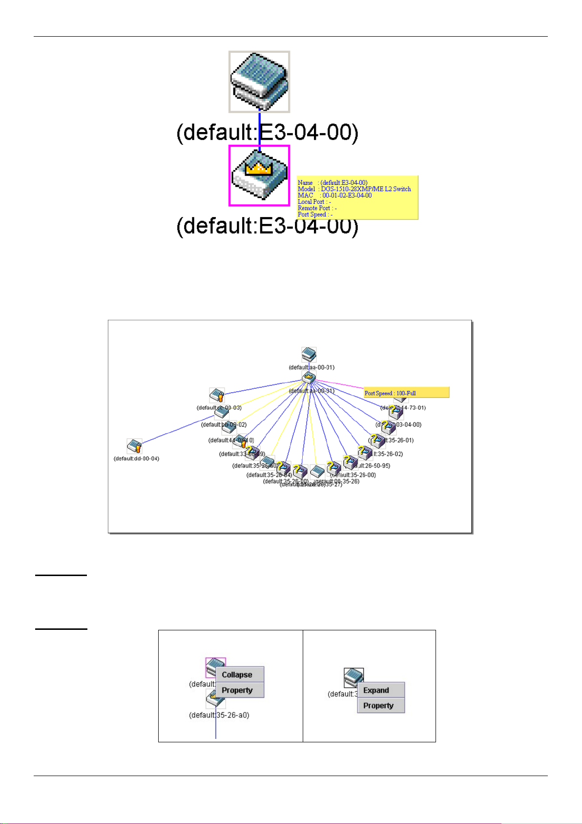
DGS-1510/ME Series Metro Ethernet Switch Web UI Reference Guide
Figure 3-17 Device Information Utilizing the Tool Tip
Setting the mouse cursor over a line between t wo devices will display the connection speed betwee n the two devices,
as shown below.
Figure 3-18 Port Speed Utilizing the Tool Tip
Right-Click
Right-clicking on a device will allow the user to perf orm various functions, depending on the rol e of the Switch in the
SIM group and the icon associated with it.
Group Icon
Figure 3-19 Right-Clicking a Group Icon
The following options may appear for the user to configure:
45
Page 54
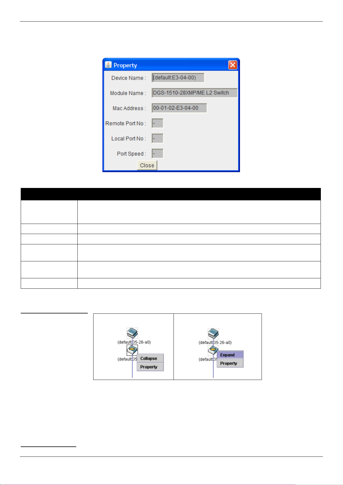
DGS-1510/ME Series Metro Ethernet Switch Web UI Reference Guide
tagged with the last six digits of the MAC Address to i dentify it.
Module Name
Displays the full module name of the switch t hat was right-clicked.
MAC Address
Displays the MAC Address of the corresponding S witch.
CS will have no entry in this field.
CS will have no entry in this field.
Port Speed
Displays the connection speed between the CS and the MS or CaS
• Collapse – To collapse the group that will be represented by a single i con.
• Expand – To expand the SIM group, in detail.
• Property – To pop up a window to display the group i nformation.
Parameter Description
Figure 3-20 Property window
Device Name
This field will display the Device Name of t he swit ches in the SIM group configured by the
user. If no Device Name is configured by the nam e, it will be given the name default and
Remote Port No
Local Port No
Displays the number of the physical port on the MS or CaS that the CS is connected to. The
Displays the number of the physical port on the CS that the MS or CaS is connected to. The
Click the Close button to close the property window.
Commander Switch Icon
Figure 3-21 Right-clicking a Commander Icon
The following options may appear for the user to configure:
• Collapse – To collapse the group that will be represented by a single icon.
• Expand – To expand the SIM group, in detail.
• Property – To pop up a window to display the group i nformation.
Member Switch Icon
46
Page 55

DGS-1510/ME Series Metro Ethernet Switch Web UI Reference Guide
Figure 3-22 Right-clicking a Member icon
The following options may appear for the user to configure:
• Collapse – To collapse the group that will be represented by a single i con.
• Expand – To expand the SIM group, in detail.
• Remove from group – Remove a member from a group.
• Configure – Launch the web management to configure the Switch.
• Property – To pop up a window to display the device information.
Candidate Switch Icon
Figure 3-23 Right-clicking a Candidate icon
The following options may appear for the user to configure:
• Collapse – To collapse the group that will be represented by a single i con.
• Expand – To expand the SIM group, in detail.
• Add to group – Add a candidate to a group. Clicking thi s opt i on wil l reveal the following dialog box for the
user to enter a password for authentication from the Candidate Switch before being added to t he S IM
group. Click OK to enter the password or Cancel to exit the dialog box.
Figure 3-24 Input password window
• Property – To pop up a window to display the device information.
Menu Bar
The Single IP Management window contains a menu bar for device configurations, as seen below.
Figure 3-25 Menu Bar of the Topology View
File
• Print Setup – Will view the image to be printed.
• Print Topology – Will print the topology map.
• Preference – Will set display properties, suc h as polling interval, and the views to open at SIM st art up.
Group
47
Page 56

DGS-1510/ME Series Metro Ethernet Switch Web UI Reference Guide
• Add to group – Add a candidate to a group. Clicking thi s opt i on will reveal the following dialog box for the
user to enter a password for authentication from the Candidate Switch before being added to the SIM
group. Click OK to enter the password or Cancel to exit the dialog box.
Figure 3-26 Input password window
• Remove from Group – Remove an MS from the group.
Device
• Configure – Will open the Web manager for the speci fic device.
View
• Refresh – Update the views with the latest status.
• Topology – Display the Topology view.
Help
1. About – Will display the SIM information, includin g the current SIM version.
Figure 3-27 About window
Firmware Upgrade
This screen is used to upgrade the firmware from the Com m ander Switch to the Member Switch. Member Switches
will be listed in the table and will be specified by ID, Port (port on the CS where the MS resides), MAC Address,
Model Name and Version. To specify a certain Switch for firmware download, click its corresponding check box
under the Port heading. To update the firmware, ent er the Server IP Address where the firmware resides and enter
the Path/Filename of the firmware. Click Download to initiate the file transfer.
To view the following window, click Management > Single IP Management > Firmware Upgrade, as show below:
Figure 3-28 Firmware Upgrade window
Configuration File Backup/Restore
This screen is used to download/upload config urat i on files from the Commander Switch to th e M em ber Switch, using a
TFTP server. Member Switches will be listed in the table and will be specified by ID, Port (port on the CS where the
MS resides), MAC Address, Model Name and Firmware Version. To download/upload the configuration file, enter
the Server IP Address where the file resides and enter the Path/Filename of the configuration file. Click Restore to
48
Page 57
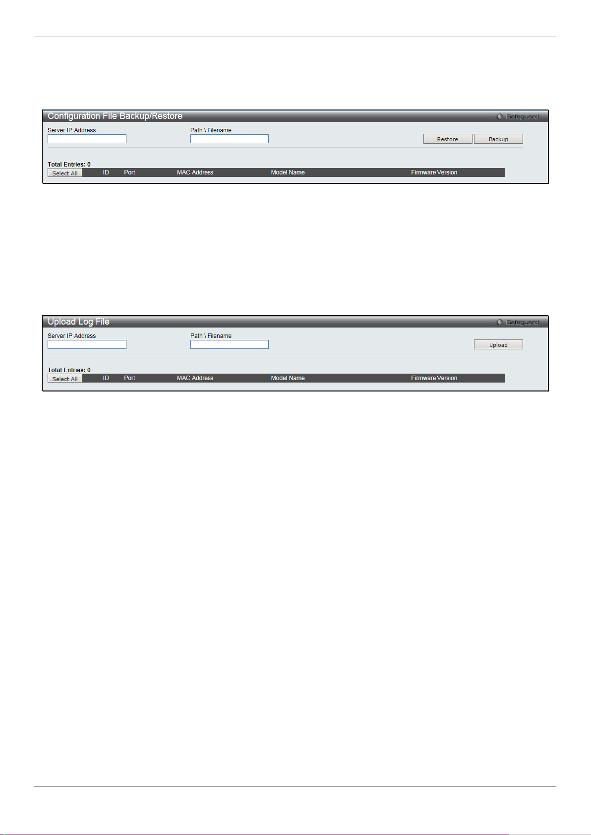
DGS-1510/ME Series Metro Ethernet Switch Web UI Reference Guide
initiate the file transfer from a TFTP server t o the Switch. Click Backup to backup the configuration file to a T FT P
server.
To view the following window, click Management > Single IP Management > Configuration File Backup/Restore,
as show below:
Figure 3-29 Configuration File Backup/Restore window
Upload Log File
The following window is used to upload log files from SIM member switches to a specified PC. To upload a log file,
enter the Server IP address of the SIM member switch and then enter a Path\Filename on your PC where you wish to
save this file. Click Upload to initiate the file transfer.
To view the following window, click Management > Single IP Management > Upload Log File, as show below:
Figure 3-30 Upload Log File window
SNMP Settings
Simple Network Management Protocol (SNMP) is an OSI Layer 7 (Application Layer) designed specifically for
managing and monitoring network devices. S NMP enables network management stations to read and modify the
settings of gateways, routers, switches, and other network devices. Use SNMP to configure system features for proper
operation, monitor performance and detect potential problems in the Switch, switch group or network.
Managed devices that support SNMP include software (referred to as an agent), which runs locally on t he device. A
defined set of variables (managed objects) is mai ntained by the SNMP agent and used to manage the de vice. These
objects are defined in a Management Inform ation Base (MIB), which provides a standard p resentation of the
information controlled by the on-board SNMP agent. SNMP defines both the format of the MIB specif ications and the
protocol used to access this information over t he network.
The Switch supports the SNMP versions 1, 2c, and 3. The three versions of SNMP vary in the level of security
provided between the management station and the network device.
In SNMPv1 and SNMPv2c, user authentication i s ac complished using ‘community strings’, which function like
passwords. The remote user SNMP application and the Switch SNMP must use the same community string. SNMP
packets from any station that has not been aut henticated are ignored (dropped).
The default community strings for the Switch used for SNMPv1 and SNMPv2c management acce ss a re:
2. public – Allows authorized management stations to retrieve M IB objects.
3. private – Allows authorized management stations to retrieve and modify MIB objects.
SNMPv3 uses a more sophisticated authentic ation process that is separated into two parts. The fi rst part is to
maintain a list of users and their attributes that are allowed to act as SNMP managers. The second part desc ribes
what each user on that list can do as an SNMP mana ger.
49
Page 58

DGS-1510/ME Series Metro Ethernet Switch Web UI Reference Guide
SNMP State
Enable this option to use the SNMP feature.
The Switch allows groups of users to be listed and configured with a shared set of privileges. The SNMP version may
also be set for a listed group of SNMP managers. Thus, you may create a group of SNMP managers that are allowed
to view read-only information or receive traps u sing SNMPv1 while assigning a higher level of securit y to another
group, granting read/write privileges using SNMPv3.
Using SNMPv3 individual users or groups of SNMP managers can be allowed to perform or be re st ricted from
performing specific SNMP management funct i ons. The functions allowed or restricted are defined using the Object
Identifier (OID) associated with a specifi c MIB. An additional layer of security is available f or SNMPv3 in that SNMP
messages may be encrypted. To read more about how to configure SNMPv3 settings for the Switch read the next
section.
Traps
Traps are messages that alert network personnel of events that occur on the Switch. The event s can be as serious as
a reboot (someone accidentally turned OFF the Switch), or less serious like a port status change. The Switch
generates traps and sends them to the trap recipi ent (or network manager). Typical traps inclu de trap messages for
Authentication Failure, Topology Change and Broadcast\Multicast Storm.
MIBs
The Switch in the Management Information B ase (MIB) stores management and counter informati on. The Switch uses
the standard MIB-II Management Information Base m odul e. Consequently, values for MIB objects can be r etrieved
from any SNMP-based network management sof tware. In addition to the standard MIB-II, the Switch also supports its
own proprietary enterprise MIB as an extended Management Information Base. Specifying the MIB Object Identifier
may also retrieve the proprietary MIB. M IB values can be either read-only or read-write.
The Switch incorporates a flexible SNMP m anagement for the switching environment. SNMP m anagement can be
customized to suit the needs of the networks and the preferences of the network administrator. Use the SNMP V3
menus to select the SNMP version used for specif ic tasks.
The Switch supports the Simple Network Management Protocol (SNMP) versions 1, 2c, and 3 . The administrator can
specify the SNMP version used to monitor and control the Switch. The three versions of SNMP v ary in the level of
security provided between the management st ation and the network device.
SNMP settings are configured using the menus located on the SNMP V3 folder of the Web manager. Workstations on
the network that are allowed SNMP privileged access to the Switch can be restricted with the M anagement Station IP
Address menu.
SNMP Global Settings
SNMP global state settings can be enabled or disabled.
To view the following window, click Management > SNMP Settings > SNMP Global Settings, as show below:
Figure 3-31 SNMP Global Settings window
The fields that can be configured are described below:
Parameter Description
Click the Apply button to accept the changes made.
50
Page 59

DGS-1510/ME Series Metro Ethernet Switch Web UI Reference Guide
SNMP Traps
Enable this option to use the SNMP Traps feature.
SNMP Authentication Trap
Enable this option to use the SNMP Authenticati on Traps feature.
Linkchange Traps
Enable this option to use the SNMP Link Change Traps feature.
Coldstart Traps
Enable this option to use the SNMP Cold Start Traps feature.
Warmstart Traps
Enable this option to use the SNMP Warm Start Traps feature.
SNMP Traps Settings
Users can enable and disable the SNMP trap support function of the switch and SNMP authentication failure trap
support, respectively.
To view the following window, click Management > SNMP Settings > SNMP Traps Settings, as show below:
Figure 3-32 SNMP Traps Settings window
The fields that can be configured are described below:
Parameter Description
Click the Apply button to accept the changes made.
SNMP Linkchange Traps Settings
On this page the user can configure the SNMP link c hange trap settings.
To view the following window, click Management > SNMP Settings > SNMP Linkchange Traps Settings, as show
below:
51
Page 60

DGS-1510/ME Series Metro Ethernet Switch Web UI Reference Guide
From Port / To Port
Select the starting and ending ports to use.
State
Use the drop-down menu to enable or disable the SN M P link change Trap.
Figure 3-33 SNMP Linkchange Traps Settings window
The fields that can be configured are described below:
Parameter Description
Click the Apply button to accept the changes made.
SNMP View Table Settings
Users can assign views to community strings that define which MIB objects can be accessed by a remote SNMP
manager. The SNMP Group created with this table m aps SNMP users (identified in the SNMP User Table) to the
views created in the previous window.
To view the following window, click Management > SNMP Settings > SNMP View Table Settings, as show below:
Figure 3-34 SNMP View Table Settings window
The fields that can be configured are described below:
52
Page 61

DGS-1510/ME Series Metro Ethernet Switch Web UI Reference Guide
being created.
tree) that will be included or excluded from access by an SNMP manager.
access.
access to MIB objects in the Switch’s SNMP agent.
must exist in the SNMP View Table.
can read from, and write to the contents of t he M IBs on the Switch.
Parameter Description
View Name
Subtree OID
View Type
Click the Apply button to accept the changes made.
Click the Delete button to remove the specific entry.
Type an alphanumeric string of up to 32 characte rs. This is used to identify the new SNMP view
Type the Object Identifier (OID) Subtree for the view. The OID identifies an object tree (MIB
Select Included to include this object in the list of objects that an SNMP manager can acce ss.
Select Excluded to exclude this object from the list of objects that an SNMP manager can
SNMP Community Table Settings
Users can create an SNMP community string to define the relationship between the SNMP manager and an agent.
The community string acts like a password to permi t access to the agent on the Switch. One or more of the following
characteristics can be associated with the community string:
1. An Access List of IP addresses of SNMP manage rs that are permitted to use the community string t o gain
access to the Switch’s SNMP agent.
2. Any MIB view that defines the subset of all M IB objects will be accessible to the SNMP community.
3. Read/write or read-only level permission for the MIB objects accessible to the SNMP commu nity.
To view the following window, click Management > SNMP Settings > SNMP Community Table Settings, as show
below:
Figure 3-35 SNMP Community Table Settings window
The fields that can be configured are described below:
Parameter Description
Community Name
View Name
Access Right
Click the Apply button to accept the changes made.
Click the Delete button to remove the specific entry.
Type an alphanumeric string of up to 32 characte rs that is used to identify members of an
SNMP community. This string is used like a password to give remote SNMP managers
Type an alphanumeric string of up to 32 characte rs that is used to identify the group of MIB
objects that a remote SNMP manager is allowed to access on the Switch. The view name
Read Only – Specify that SNMP community members using the community string created
can only read the contents of the MIBs on the Switch.
Read Write – Specify that SNMP community mem bers using the community string created
53
Page 62

DGS-1510/ME Series Metro Ethernet Switch Web UI Reference Guide
SNMP group of SNMP users.
Read View Name
This name is used to specify the SNMP group created can request SNMP messages.
Switch’s SNMP agent.
generated by the Switch’s SNMP agent.
the network.
Switch and a remote SNMP manger will be encrypted.
SNMP Group Table Settings
An SNMP Group created with this table maps SNMP user s (identified in the SNMP User Table) to the views created in
the previous window.
To view the following window, click Management > SNMP Settings > SNMP Group Table Settings, as show below:
Figure 3-36 SNMP Group Table Settings window
The fields that can be configured are described below:
Parameter Description
Group Name
Write View Name
Notify View Name
User-based Security
Model
Security Level
Type an alphanumeric string of up to 32 characte rs. This is used to identify the new
Specify a SNMP group name for users that are allowed SNMP write privileges to the
Specify a SNMP group name for users that can rec eive SNMP trap messages
SNMPv1 – Specify that SNMP version 1 will be used.
SNMPv2 – Specify that SNMP version 2c will be used. The SNMPv2 supports both
centralized and distributed network managem ent strategies. It includes improvements in
the Structure of Management Information (SMI) and adds some security features.
SNMPv3 – Specify that the SNMP version 3 will be used. SNMPv3 provides secure
access to devices through a combination of authentication and encrypting packets over
The Security Level settings only apply to SNMP v3.
NoAuthNoPriv – Specify that there will be no authorization and no encryption of packets
sent between the Switch and a remote SNMP manager.
AuthNoPriv – Specify that authorization will be required, but t here will be no encryption
of packets sent between the Switch and a remote SNM P manager.
AuthPriv – Specify that authorization will be required, and that packets sent between the
Click the Apply button to accept the changes made.
Click the Delete button to remove the specific entry.
SNMP Engine ID Settings
The Engine ID is a unique identifier used for SNMP V 3 i m plem entations on the Switch.
To view the following window, click Management > SNMP Settings > SNMP Engine ID Settings, as show below:
54
Page 63

DGS-1510/ME Series Metro Ethernet Switch Web UI Reference Guide
sixth to eleventh octets is the MAC address.
User Name
An alphanumeric string of up to 32 characters. T his is used to identify the SNMP users.
Group Name
This name is used to specify the SNMP group create d can request SNMP messages.
SNMP Version
V3 – Indicates that SNMP version 3 is in use.
SNMP V3 mode. The choices are None, Password, or Key.
has been checked. This field will require the user to enter a password.
Priv-Protocol
None – Specify that no authorization protocol is in use.
Figure 3-37 SNMP Engine ID Settings window
The fields that can be configured are described below:
Parameter Description
Engine ID
Click the Apply button to accept the changes made.
NOTE: The Engine ID length is 10-64 and accepted characters can range from 0 to F.
To change the Engine ID, type the new Engine ID val ue i n the space provided. The SNMP
engine ID displays the identification of the SNMP engine on the Switch. The default value is
suggested in RFC2271. The very first bit i s 1, and the first four octets are set to the binary
equivalent of the agent’s SNMP management private enterprise number as assigned by IANA
(D-Link is 171). The fifth octet is 03 to indicat e the rest is the MAC address of this device. The
SNMP User Table Settings
This window displays all of the SNMP User’ s currently configured on the Switch.
To view the following window, click Management > SNMP Settings > SNMP User Table Settings, as show below:
Figure 3-38 SNMP User Table Settings window
The fields that can be configured are described below:
Parameter Description
SNMP V3 Encryption
Auth-Protocol
Use the drop-down menu to enable encryption for SNMP V3. This is only operable in
MD5 – Specify that the HMAC-MD5-96 authentication level will be used. This field is
only operable when V3 is selected in the SNMP Version field and the Encryption field
has been checked. This field will require the user to enter a password.
SHA – Specify that the HMAC-SHA authenticatio n protocol will be used. This field is
only operable when V3 is selected in the SNMP Version field and the Encryption field
55
Page 64

DGS-1510/ME Series Metro Ethernet Switch Web UI Reference Guide
password.
host for the Switch.
SNMPv3 – Specify that SNMP version 3 will be used.
level.
SNMPv3 User Name
DES – Specify that DES 56-bit encryption is in use, based on the CBC-DES (DES-56)
standard. This field is only operable when V3 is selected in the SNMP Version field and
the Encryption field has been checked. This fiel d wil l require the user to enter a
Click the Apply button to accept the changes made.
Click the Delete button to remove the specific entry.
SNMP Host Table Settings
Users can set up SNMP trap recipients for IPv4.
To view the following window, click Management > SNMP Settings > SNMP Host Table Settings, as show below:
Figure 3-39 SNMP Host Table Settings window
The fields that can be configured are described below:
Parameter Description
Host IP Address
User-based Security
Model
Security Level
Community String /
Click the Apply button to accept the changes made.
Click the Delete button to remove the specific entry.
Type the IP address of the remote management station that will serve as the SNMP
SNMPv1 – Specify that SNMP version 1 will be used.
SNMPv2 – Specify that SNMP version 2 will be used.
NoAuthNoPriv – To specify that the SNMP version 3 will be used, with a NoAuth-NoPriv
security level.
AuthNoPriv – To specify that the SNMP version 3 will be used, with an Auth-NoPriv
security level.
AuthPriv – To specify that the SNMP version 3 will be used, wit h an Auth-Priv security
Type in the community string or SNMP V3 user name as appropriate.
RMON Settings
On this page the user can enable or disable remote monitoring (RMON) for the rising and fall ing alarm trap feature for
the SNMP function on the Switch.
To view the following window, click Management > SNMP Settings > RMON Settings, as show belo w:
56
Page 65
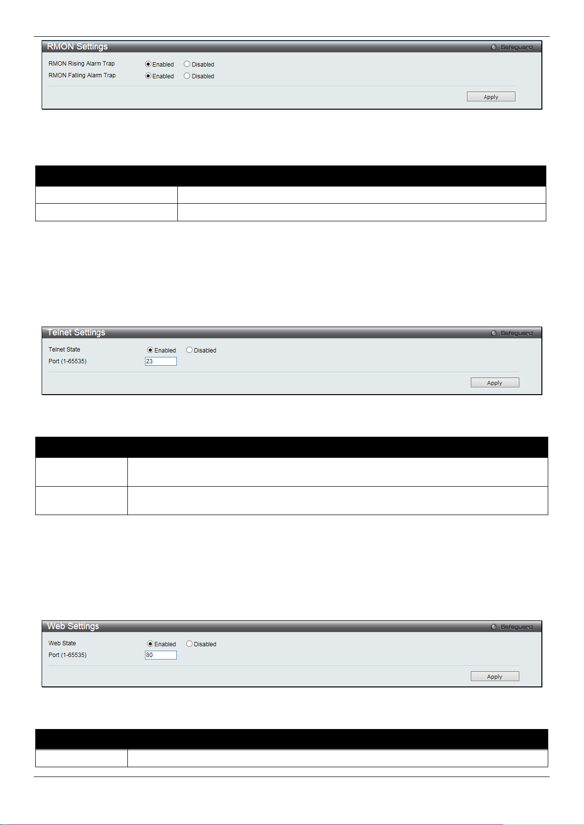
DGS-1510/ME Series Metro Ethernet Switch Web UI Reference Guide
RMON Rising Alarm Trap
Enable this option to use the RMON Rising Alarm T rap Feature.
RMON Falling Alarm Trap
Enable this option to use the RMON Falling Alarm Trap Feature.
system through Telnet choose Disabled.
for the Telnet protocol is 23.
Web Status
Web-based management is Enabled by default. If you choose to disable this by clicking
Figure 3-40 RMON Settings window
The fields that can be configured are described below:
Parameter Description
Click the Apply button to accept the changes made.
Telnet Settings
Users can configure Telnet Settings on the Switch.
To view the following window, click Management > Telnet Settings, as show below:
Figure 3-41 Telnet Settings window
The fields that can be configured are described below:
Parameter Description
Telnet State
Port (1-65535)
Click the Apply button to accept the changes made.
Telnet configuration is Enabled by default . If you do not want to allow configuration of the
The TCP port number used for Telnet manag em ent of the Switch. The “well-known” TCP port
Web Settings
Users can configure the Web settings on the S witch.
To view the following window, click Managemen t > Web Settings, as show bel ow:
Figure 3-42 Web Settings window
The fields that can be configured are described below:
Parameter Description
57
Page 66

DGS-1510/ME Series Metro Ethernet Switch Web UI Reference Guide
Disabled, you will lose the ability to configure the system through the web interface as soon as
these settings are applied.
port for the Web protocol is 80.
Port (1-65535)
The TCP port number used for web-based management of the Switch. The “well-known” TCP
Click the Apply button to accept the changes made.
58
Page 67

DGS-1510/ME Series Metro Ethernet Switch Web UI Reference Guide
Chapter 4 L2 Features
VLAN
QinQ
Layer 2 Protocol Tunneling Settings
Spanning Tree
Link Aggregation
FDB
L2 Multicast Control
Multicast Filtering
ERPS Settings
LLDP
NLB FDB Settings
VLAN
Understanding IEEE 802.1p Priority
Priority tagging is a function defined by the IEE E 802.1p standard designed to provide a means of managing traffic on
a network where many different types of data m ay be transmitted simultaneously. It is intended to alleviate problems
associated with the delivery of time crit i cal data over congested networks. The quality of applicat ions that are
dependent on such time critical data, such as vi deo conferencing, can be severely and adversely affected by even
very small delays in transmission.
Network devices that are in compliance wit h the IEEE 802.1p standard have the ability to recognize the priority level of
data packets. These devices can also assign a priority label or tag to packets. Compliant device s can also strip priority
tags from packets. This priority tag determines t he packet’s degree of expeditiousness and determines the queue to
which it will be assigned.
Priority tags are given values from 0 to 7 with 0 being assigned to the lowest priority data and 7 assigne d to the
highest. The highest priority tag 7 is generally only used for data associated with video or audio applications, which
are sensitive to even slight delays, or for data from specified end users whose data transmissi ons warrant special
consideration.
The Switch allows you to further tailor how prio rity tagged data packets are handled on your network. Using queues to
manage priority tagged data allows you to specify its relative priority to suit the needs of your network. There may be
circumstances where it would be advantageous to group two or more di fferently tagged packets into the same queue.
Generally, however, it is recommended that the highest priority queue, Queue 7, be reserved f or data packets with a
priority value of 7. Packets that have not been give n any priority value are placed in Queue 0 and thus give n the
lowest priority for delivery.
Strict mode and weighted round robin system are employed on the Switch to determine the rate at which the queues
are emptied of packets. The ratio used for clearing t he queues is 4:1. This means that the highest pri ority queue,
Queue 7, will clear 4 packets for every 1 packet cleared from Queue 0.
Remember, the priority queue settings on the Switch are for all ports, and all devices connected to the Switch will be
affected. This priority queuing system will be especially beneficial if your network employs switches with the capability
of assigning priority tags.
VLAN Description
A Virtual Local Area Network (VLAN) is a network topology configured according to a logical scheme rathe r than the
physical layout. VLANs can be used to combine any collection of LAN segments into an autonomous user group that
appears as a single LAN. VLANs also logically segme nt the network into different broadcast domains so th at packets
are forwarded only between ports within the VLA N. Typically, a VLAN corresponds to a particular subnet, although not
necessarily.
VLANs can enhance performance by conserving bandwi dth, and improve security by limiting traffic to speci fic domains.
59
Page 68

DGS-1510/ME Series Metro Ethernet Switch Web UI Reference Guide
A VLAN is a collection of end nodes grouped by logic instead of physical location. End nodes that frequentl y
communicate with each other are assigned to the same VLAN, regardless of where they are physically on the network.
Logically, a VLAN can be equated to a broadcast domain, because broadcast packets are forwarded t o only members
of the VLAN on which the broadcast was initiated.
Notes about VLANs on the Switch
• No matter what basis is used to uniquely i dentify end nodes and assign these nodes VLAN membe rship,
packets cannot cross VLANs without a netwo rk device performing a routing function between the VLANs.
• The Switch supports IEEE 802.1Q VLANs. Th e port untagging function can be used to remove the 802.1Q tag
from packet headers to maintain compatibili ty with devices that are tag-unaware.
• The Switch’s default is to assign all ports to a single 802.1Q VLAN named “default.”
• The “default” VLAN has a VID = 1.
• The member ports of Port-based VLANs may overlap, if desired.
IEEE 802.1Q VLANs
Some relevant terms:
• Tagging – The act of putting 802.1Q VLAN information i nto the header of a packet.
• Untagging – The act of stripping 802.1Q VLAN information out of the packet header.
• Ingress port – A port on a switch where packets are flowing into the Switch and VLAN decisions must be
made.
• Egress port – A port on a switch where packets are flowing out of the Switch, either to another switch or to an
end station, and tagging decisions must be made.
IEEE 802.1Q (tagged) VLANs are implemented on the Switch. 802.1Q VLANs require tagging, whic h enables them to
span the entire network (assuming all switches on the network are IEEE 802.1Q-compliant).
VLANs allow a network to be segmented in order t o reduce the size of broadcast domains. All packet s entering a
VLAN will only be forwarded to the stations (over IE EE 802.1Q enabled switches) that are members of that VLAN, and
this includes broadcast, multicast and uni cast packets from unknown sources.
VLANs can also provide a level of security t o your network. IEEE 802.1Q VLANs will only deliver packets between
stations that are members of the VLAN.
Any port can be configured as either tagging or untagging. The untagging feature of IEEE 802.1Q VLA Ns allows
VLANs to work with legacy switches that don’t recognize VLAN tags in packet headers. The tagging feature allows
VLANs to span multiple 802.1Q-compliant switches through a single physical connection an d al l ows Spanning Tree to
be enabled on all ports and work normally.
The IEEE 802.1Q standard restricts the forwarding of untagged packets to the VLAN the receiving port is a member of.
60
Page 69

DGS-1510/ME Series Metro Ethernet Switch Web UI Reference Guide
Figure 4-1 IEEE 802.1Q Packet Forwarding
The main characteristics of IEEE 802.1Q are as fol l ows:
1. Assigns packets to VLANs by filtering.
2. Assumes the presence of a singl e global spanning tree.
3. Uses an explicit tagging scheme with one-level t agging.
4. 802.1Q VLAN Packet Forwarding
5. Packet forwarding decisions are made based upo n the following three types of rules:
Ingress rules – rules relev ant to the classification of received frames bel ongi ng to a VLAN.
Forwarding rules b etween ports – decides whether to filter or forward the packet.
Egress rule s – determines if the packet must be sent tagged or untagged.
802.1Q VLAN Tags
The figure below shows the 802.1Q VLAN tag. There are four additional octets inserted after the source MAC address.
Their presence is indicated by a value of 0x8100 in t he EtherType field. When a packet’s EtherType field i s equal to
0x8100, the packet carries the IEEE 802.1Q/802.1p tag. The tag is contained in the following two octets and consists
of 3 bits of user priority, 1 bit of Canonical F ormat Identifier (CFI – used for encapsulating Token Ring packets so they
can be carried across Ethernet backbones), an d 12 bits of VLAN ID (VID). The 3 bits of user priority are used by
802.1p. The VID is the VLAN identifier and is used by the 802.1Q standard. Because the VID is 12 bits long, 4094
unique VLANs can be identified.
The tag is inserted into the packet header making the entire packet longer by 4 octets. All of the informat i on originally
contained in the packet is retained.
61
Page 70

DGS-1510/ME Series Metro Ethernet Switch Web UI Reference Guide
0 1
2 3 4
Destination Address (6 octets)
Source Address (6 octets)
EtherType=0x8100
MAC Length/Type Beginning of Data
Cyclic Redundancy Check (4 octets)
User Prlorlty CFI VLAN ID (VID) (12 bits)
Tag Control Information
Dst. MAC Src. MAC
Dst. MAC Src. MAC
Tag Control Information (TCI)
4
Up to 15006
16 3 1 12
6 2 4
Up to 15006 6 2 4
Original Ethernet Packet
New Tagged Packet
bytes
bytes
bites
Figure 4-2 IEEE 802.1Q Tag
The EtherType and VLAN ID are inserted after the MAC source address, but before the original EtherType/Length or
Logical Link Control. Because the packet is now a bi t longer than it was originally, the Cyclic Redundancy Check
(CRC) must be recalculated.
Port VLAN ID
Figure 4-3 Adding an IEEE 802.1Q Tag
62
Page 71

DGS-1510/ME Series Metro Ethernet Switch Web UI Reference Guide
Packets that are tagged (are carrying the 802. 1Q VID information) can be transmitted from one 802.1Q compliant
network device to another with the VLAN information intact. This allows 802.1Q VLANs to span network devices (and
indeed, the entire network, if all network devices are 802.1Q compliant).
Unfortunately, not all network devices are 802. 1Q compliant. These devices are referred to as tag-unaware. 802.1Q
devices are referred to as tag-aware.
Prior to the adoption of 802.1Q VLANs, port-based and MAC-based VLANs were in common use. These VLANs reli ed
upon a Port VLAN ID (PVID) to forward packets. A packet received on a given port would be assigned that port’s PVID
and then be forwarded to the port that correspon ded to the packet’s destination address (found in the Switch’s
forwarding table). If the PVID of the port that received the packet is different from the PVID of the port that is to
transmit the packet, the Switch will drop the packet.
Within the Switch, different PVIDs mean di fferent VLANs (remember that two VLANs cannot com m unicate without an
external router). So, VLAN identification based upon the PVIDs cannot create VLANs that extend outside a given
switch (or switch stack).
Every physical port on a switch has a PVID. 802.1Q ports are also assigned a PVID, for use within the S witch. If no
VLANs are defined on the Switch, all ports are then assigned to a default VLAN with a PVID equal to 1. Untagged
packets are assigned the PVID of the port on which t hey were received. Forwarding decisions are based upon this
PVID, in so far as VLANs are concerned. Tagged packets are forwarded according to the VID contained within the tag.
Tagged packets are also assigned a PVID, but the PVID is not used to make packet-forwarding decisions, the VID is.
Tag-aware switches must keep a table to relate P V IDs within the Switch to VIDs on the network. The S witch will
compare the VID of a packet to be transmitt ed to the VID of the port that is to transmit the packet . If the two VIDs are
different, the Switch will drop the packet. Because of the existence of the PVID for untagged packets and the VID for
tagged packets, tag-aware and tag-unaware network devices can coexist on the same network.
A switch port can have only one PVID, but can have as many VIDs as the Switch has memory in its VLAN t abl e to
store them.
Because some devices on a network may be tag-una ware, a decision must be made at each port on a tag-aware
device before packets are transmitted – should the packet to be transmitted have a tag or not? If the transmitting port
is connected to a tag-unaware device, the packet s hould be untagged. If the transmitting port is co nnected to a tagaware device, the packet should be tagged.
Tagging and Untagging
Every port on an 802.1Q compliant switch can be configured as tagging or untagging.
Ports with tagging enabled will put the VID numb er, priority and other VLAN information into the header of all packets
that flow into and out of it.
If a packet has previously been tagged, the port will not alter the packet, thus keeping the VLAN information intact.
Other 802.1Q compliant devices on the netwo rk t o make packet-forwarding decisions can then use the VL AN
information in the tag.
Ports with untagging enabled will strip the 802.1Q tag from all packets that flow into and out of those ports. If the
packet doesn’t have an 802.1Q VLAN tag, t he port will not alter the packet. Thus, all packets receiv ed by and
forwarded by an untagging port will have no 802.1 Q VLAN information. (Remember that the PVID is only used
internally within the Switch). Untagging is used to send packets from an 802.1Q-compliant network device to a noncompliant network device.
Ingress Filtering
A port on a switch where packets are flowing into t he Switch and VLAN decisions must be made is referred to as an
ingress port. If ingress filtering is enabled f or a port , the Switch will examine the VLAN information in the packet
header (if present) and decide whether or not t o forward the packet.
If the packet is tagged with VLAN informat i on, the ingress port will first determine if the ingress port itself is a member
of the tagged VLAN. If it is not, the packet wil l be dropped. If the ingress port is a member of the 802.1Q VLAN, the
63
Page 72

DGS-1510/ME Series Metro Ethernet Switch Web UI Reference Guide
packets will also be flooded to all ports.
System (default)
1
5, 6, 7
Engineering
2
9, 10
Sales
5
1, 2, 3, 4
Switch then determines if the destination port i s a m ember of the 802.1Q VLAN. If it is not, the packet is dropped. If
the destination port is a member of the 802.1Q VLA N, the packet is forwarded and the destination port transmits it to
its attached network segment.
If the packet is not tagged with VLAN informati on, the ingress port will tag the packet with its own P VID as a VID (if the
port is a tagging port). The switch then determines if the destination port is a member of the same V LAN (has the
same VID) as the ingress port. If it does not, the packet is dropped. If it has the same VID, the packet is f orwarded and
the destination port transmits it on its attached network segment.
This process is referred to as ingress filtering and is used to conserve bandwidth within the Switch by dr opping
packets that are not on the same VLAN as the ingres s port at the point of reception. This eliminates the sub sequent
processing of packets that will just be dropped by the destination port.
Default VLANs
The Switch initially configures one VLAN, VID = 1, called “default.” The factory default setting as signs all ports on the
Switch to the “default.” As new VLANs are confi gured in Port-based mode, their respective member ports are removed
from the “default.”
Packets cannot cross VLANs. If a member of one VLA N wants to connect to another VLAN, the link must be through
an external router.
NOTE: If no VLANs are configured on the Switch, then all packets will be forwarded to any destination
port. Packets with unknown source addresses will be flooded to all ports. Broadcast and multicast
An example is presented below:
VLAN Name VID Switch Ports
Port-based VLANs
Port-based VLANs limit traffic that flows into and out o f switch ports. Thus, all devices connected to a port are
members of the VLAN(s) the port belongs to, whether there is a single computer directly connect ed to a switch, or an
entire department.
On port-based VLANs, NICs do not need to be able to identify 802.1Q tags in packet headers. NICs send and receive
normal Ethernet packets. If the packet’s dest i nation lies on the same segment, communications take place using
normal Ethernet protocols. Even though t hi s is always the case, when the destination for a packet li es on another
switch port, VLAN considerations come i nto play to decide if the packet gets dropped by the S witch or delivered.
VLAN Segmentation
Take for example a packet that is transmit ted by a machine on Port 1 that is a member of VLAN 2. If the destination
lies on another port (found through a normal for warding table lookup), the Switch then looks to see if the other port
(Port 10) is a member of VLAN 2 (and can therefore receive VLAN 2 packets). If Port 10 is not a member of VLAN 2,
then the packet will be dropped by the Switch and will not reach its destination. If Port 10 is a member of V LAN 2, the
packet will go through. This selective forwar di ng feature based on VLAN criteria is how VLANs segment networks.
The key point being that Port 1 will only transmit on VLA N 2.
802.1Q VLAN Settings
The VLAN List tab lists all previously configured VLANs by VLAN I D and VLAN Name.
To view the following window, click L2 Features > VL AN > 802.1Q VLAN Settings, as show below:
64
Page 73
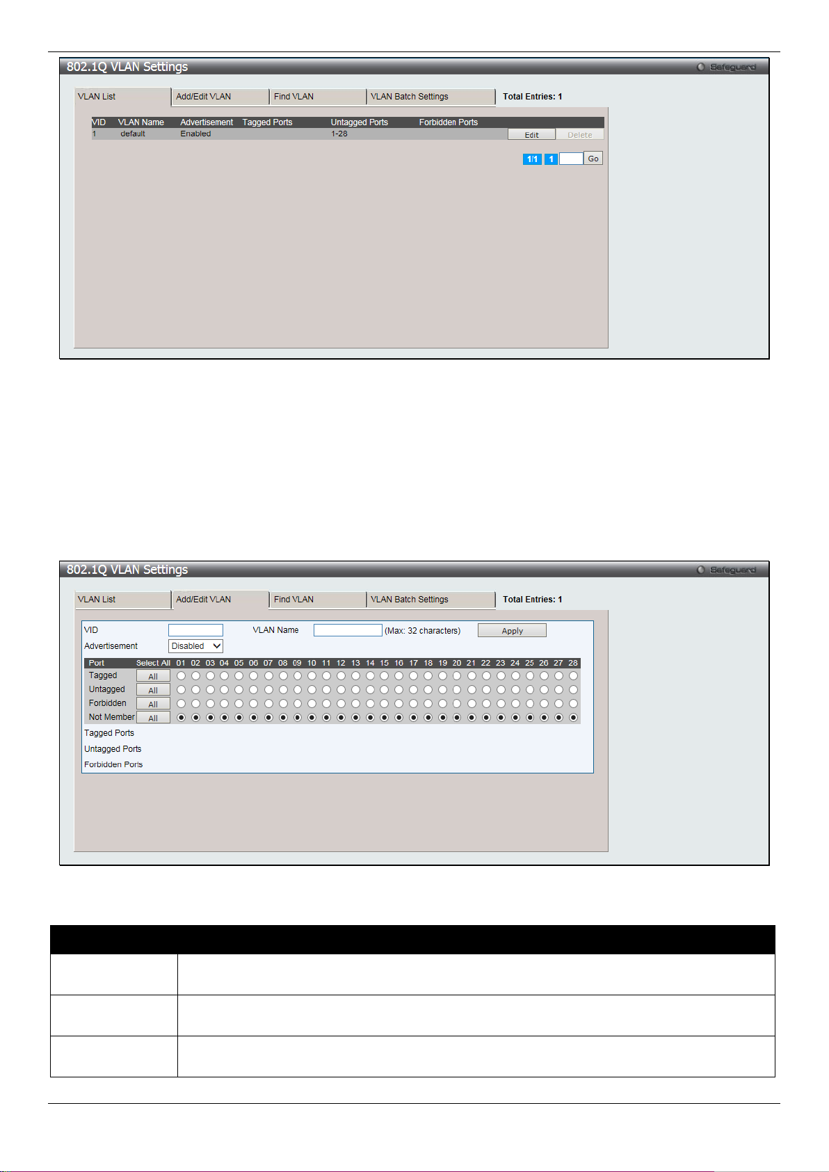
DGS-1510/ME Series Metro Ethernet Switch Web UI Reference Guide
VLAN tab. VLANs can be identified by either the VID or t he VLAN name.
VLAN tab.
notifying that they may join the existing VLAN.
Figure 4-4 802.1Q VLAN Settings –VLAN List Tab window
Click the Edit button to re-configure the specific entry.
Click the Delete button to remove the specific entry.
Enter a page number and click the Go button to navigate to a specific page when multiple pages exist.
To create a new 802.1Q VLAN or modify an existing 802. 1Q V LAN, click the Add/Edit VLAN tab.
A new tab will appear, as shown below, to configure t he port settings and to assign a unique name and num ber to the
new VLAN.
Figure 4-5 802.1Q VLAN Settings – Add/Edit VLAN Tab window
The fields that can be configured are described below:
Parameter Description
VID
VLAN Name
Advertisement
Allow the entry of a VLAN ID or displays the VLAN ID of an existing VLAN in the Add/Edit
Allow the entry of a name for the new VLAN or for editing the VLAN name in the Add/Edit
Enable this function to allow the Switch sending out GVRP packets to outside sources,
65
Page 74

DGS-1510/ME Series Metro Ethernet Switch Web UI Reference Guide
Port
Display all ports of the Switch for the configuration option.
Click the All button to select all ports.
untagged. Click the All button to select all ports.
all ports.
the All button to select all ports.
Tagged
Untagged
Forbidden
Specify the port as 802.1Q tagging. Clicking the radio button will designate the port as tagged.
Specify the port as 802.1Q untagged. Clicking the radio button will designate the port as
Click the radio button to specify the port as not being a member of the VLAN and that the port
is forbidden from becoming a member of the V LAN dynamically. Click the All button to select
Not Member
Click the radio button to allow an individual port to be specified as a non-VLAN member. Click
Click the Apply button to accept the changes made.
To search for a VLAN, click the Find VLAN tab. A new tab will ap pear, as shown below.
Figure 4-6 802.1Q VLAN Settings – Find VLAN Tab window
Enter the VLAN ID number in the field offered and then click the Find button. You will be redirected to the VLAN List
tab.
To create, delete and configure a VLAN Batch entry click the VLAN Batch Settings tab, as sh own below.
Figure 4-7 802.1Q VLAN Settings – VLAN Batch Settings Tab window
The fields that can be configured are described below:
66
Page 75

DGS-1510/ME Series Metro Ethernet Switch Web UI Reference Guide
VID List
Enter a VLAN ID List that can be added, deleted o r configured.
notifying that they may join the existing VLAN.
Port List
Allows an individual port list to be added or deleted as a member of the VLAN.
tagged.
untagged.
port as forbidden.
Group ID (1-16)
Select an ID number for the group, between 1 and 16.
32 characters.
toggle between Ethernet II, IEEE802.3 SNAP, and IEEE802.3 LLC.
Protocol Value (0-
Enter a value for the Group. The protocol value is used to identi fy a protocol of the frame
Parameter Description
Advertisement
Tagged
Untagged
Forbidden
Click the Apply button to accept the changes made.
NOTE: The Switch supports up to 4k static VLAN entries.
Enabling this function will allow the Switch to send out GVRP packets to outside sources,
Specify the port as 802.1Q tagged. Use the drop-down menu to designate the port as
Specify the port as 802.1Q untagged. Use the d rop-down menu to designate the port as
Specify the port as not being a member of the VLAN and t hat the port is forbidden from
becoming a member of the VLAN dynamically. Us e the drop-down menu to designate the
802.1v Protocol VLAN
802.1v Protocol Group Setti ng s
The user can create Protocol VLAN groups and add protocols to that group. The 802.1v Protocol V LAN Group
Settings support multiple VLANs for each proto col and allows the user to configure the untagged ports of di fferent
protocols on the same physical port. For ex am pl e, it allows the user to configure an 802.1Q and 802. 1v untagged port
on the same physical port. The lower half of t he table displays any previously created groups.
To view the following window, cli ck L2 Features > VLAN > 802.1v protocol VLAN > 802.1v Protocol Group
Settings, as show below:
Figure 4-8 802.1v Protocol Group Settings window
The fields that can be configured are described below:
Parameter Description
Group Name
Protocol
This is used to identify the new Protocol VLAN group. Type an alphanumeric string of up to
This function maps packets to protocol-defined VLANs by examining the type octet within the
packet header to discover the type of protocol associated with it. Use the drop-down menu to
67
Page 76

DGS-1510/ME Series Metro Ethernet Switch Web UI Reference Guide
FFFF)
type specified. The form of the input is 0x0 t o 0xffff. Depending on the frame type, the octet
the second octet is for Source.
Group ID
Select a previously configured Group ID from the drop-down menu.
Group Name
Select a previously configured Group Name from the drop-down menu.
create.
create.
section of this manual.
string will have one of the following values: For E thernet II, this is a 16-bit (2-octet) hex
value. For example, IPv4 is 800, IPv6 is 86dd, ARP is 806, etc. For IEEE802.3 SNAP, this is
a 16-bit (2-octet) hex value. For IEEE802.3 LLC, this is a 2-octet IEEE 802.2 Link Service
Access Point (LSAP) pair. The first octet is for Destination Service Access Point (DSAP) and
Click the Add button to add a new entry based on the information ent ered.
Click the Delete All button to remove all the entries based on the information entered.
Click the Edit button to re-configure the specific entry.
Click the Delete Settings button to remove the Protocol for the Protocol VLAN Group information for the specific entry.
Click the Delete Group button to remove the entry completely.
NOTE: The Group name value should be less than 33 characters.
802.1v Protocol VLAN Setting s
The user can configure Protocol VLAN settings. The lower half of the table displays any previ ously created settings.
To view the following window, click L2 Features > VL AN > 802.1v protocol VLAN > 802.1v Protocol VLAN
Settings, as show below:
Figure 4-9 802.1v Protocol VLAN Settings window
The fields that can be configured are described below:
Parameter Description
VID (1-4094)
VLAN Name
802.1p Priority
This is the VLAN ID that, along with the VLAN Name, identifies the VLAN the user wishes to
This is the VLAN Name that, along with the VLAN ID, identifies the VLAN the user wi shes to
This parameter is specified if you want to re-write the 802.1p default priority previously set in
the Switch, which is used to determine the CoS queu e to which packets are forwarded to.
Once this field is specified, packets accept ed by the Switch that match this priority are
forwarded to the CoS queue specified previously by the user.
Click the corresponding box if you want to set the 802.1p default priority of a packet to the
value entered in the Priority (0-7) field, which me ets the criteria specified previously in this
command, before forwarding it on to the specifi ed CoS queue. Otherwise, a packet will have
its incoming 802.1p user priority re-written to its original value before being forwarded by the
Switch.
For more information on priority queues, CoS queues and mapping for 802.1p, see the QoS
68
Page 77

DGS-1510/ME Series Metro Ethernet Switch Web UI Reference Guide
tick the All Ports check box.
button.
GVRP State
Click the radio buttons to enable or disable the GVRP State.
Join Time (100-100000)
Enter the Join Time value in milliseconds.
Leave Time (100-100000)
Enter the Leave Time value in milliseconds.
100000)
site. It can use 802.1D GVRP address or 802.1ad se rvice provider GVRP address.
Port List
Search Port List
Click the Add button to add a new entry based on the information ent ered.
Click the Find button to locate a specific entry based on the inf ormation entered.
Click the Show All button to display all the Protocol VLANs configured.
Click the Delete All button to remove all the entries listed.
Click the Edit button to re-configure the specific entry.
Click the Delete button to remove the specific entry.
Select the specified ports you wish to configure by entering the port number in this field, or
This function allows the user to search all previously configured port list settings and display
them on the lower half of the table. To search for a p ort l ist enter the port number you wish to
view and click Find. To display all previously configured port l i st s on the bottom half of the
screen click the Show All button, to clear all previously config ured lists click the Delete All
GVRP
GVRP Global Settings
Users can determine whether the Switch will share its VLAN configuration information with other GARP VLAN
Registration Protocol (GVRP) enabled switches. In addition, Ingress Checking can be used to limi t traffic by filtering
incoming packets whose PVID does not match the PVID of the port. Results can be seen in the table under the
configuration settings.
To view the following window, click L2 Features > VLAN > GVRP > GVRP Global Settings, as show below:
Figure 4-10 GVRP Global Settings window
The fields that can be configured are described below:
Parameter Description
Leave All Time (100-
NNI BPDU Address
Click the Apply button to accept the changes made for each individual section.
Enter the Leave All Time value in milliseconds.
Used to determine the GVRP PDU protocol addr ess for GVRP in service provide
69
Page 78

DGS-1510/ME Series Metro Ethernet Switch Web UI Reference Guide
From Port / To Port
Select the starting and ending ports to use.
will drop the packet. If the two are equal, the port wil l rec ei ve the packet.
become a member of a VLAN. GVRP is Disabled by default.
discarded.
accepted, and All, which mean both tagged and untagged frames will be accepted. All
NOTE: The Leave Time value should be greater than twice the Join Time value. The Leave All Time
value should be greater than the Leave Time value.
GVRP Port Settings
On this page the user can configure the GVRP po rt parameters.
To view the following window, click L2 Features > VLAN > GVRP > GVRP Port Settings, as show below:
Figure 4-11 GVRP Port Settings window
The fields that can be configured are described below:
Parameter Description
PVID (1-4094)
GVRP
Ingress Checking
This field is used to manually assign a PVID to a V LA N. The S witch's default is to
assign all ports to the default VLAN with a VI D of 1.The PVID is used by the port to
tag outgoing, untagged packets, and to make filtering decisions about incoming
packets. If the port is specified to accept onl y tagged frames - as tagging, and an
untagged packet is forwarded to the port f or transmission, the port will add an 802.1Q
tag using the PVID to write the VID in the tag. When the packet arrives at its
destination, the receiving device will use the P VID to make VLAN forwarding
decisions. If the port receives a packet, and Ingr ess filtering is Enabled, the port will
compare the VID of the incoming packet to i ts PVID. If the two are unequal, the port
The GARP VLAN Registration Protocol (GVRP ) enables the port to dynamically
This drop-down menu allows the user to enable the port to compare the VID tag of an
incoming packet with the port VLAN membershi p. If enable ingress checking and the
reception port is not the member port of the frame’s VLAN, the frame shall be
Acceptable Frame Type
This field denotes the type of frame that will be accepted by the port. The user may
choose between Tagged Only, which means only VLAN tagged frames will be
70
Page 79

DGS-1510/ME Series Metro Ethernet Switch Web UI Reference Guide
is enabled by default.
MAC Address
Specify the MAC address.
VID (1-4094)
Select this option and enter the VLAN ID.
VLAN Name
Select this option and enter the VLAN name of a previously configured VLAN.
Click the Apply button to accept the changes made.
MAC-based VLAN Settings
Users can create new MAC-based VLAN entries, search and delete existing entries. When a static M A C-based VLAN
entry is created for a user, the traffic from t hi s us er will be able to be serviced under the specified VLA N.
To view the following window, click L2 Features > VL AN > MAC-based VLAN Settings, as show below:
Figure 4-12 MAC-based VLAN Settings
The fields that can be configured are described below:
Parameter Description
Click the Find button to locate a specific entry based on the inf ormation entered.
Click the Add button to add a new entry based on the information ent ered.
Click the View All button to display all the existing entries.
Click the Delete All button to remove all the entries listed.
Click the Delete button to remove the specific entry.
Enter a page number and click the Go button to navigate to a specific page when multiple pages exist.
PVID Auto Assign Settings
Users can enable or disable PVID Auto Assign Status. The default setting is enabled.
To view the following window, click L2 Features > VL AN > PVID Auto Assign Settings, as show below:
Figure 4-13 PVID Auto Assign Settings windo w
Click the Apply button to accept the changes made.
VLAN Trunk Settings
Enable VLAN on a port to allow frames belonging to unknown VLAN groups to pass through that port. T hi s is useful if
you want to set up VLAN groups on end devices without having to configure the same VLAN groups on intermediary
devices.
Suppose you want to create VLAN groups 1 and 2 (V1 and V2) on devices A and B. Without a VLAN Trunk, you must
first configure VLAN groups 1 and 2 on all intermediary switches C, D and E; otherwise they will drop frames with
71
Page 80

DGS-1510/ME Series Metro Ethernet Switch Web UI Reference Guide
VLAN Trunk State
Enable or disable the VLAN trunking global state.
By clicking the Clear All button, all the ports will not be included.
unknown VLAN group tags. However, with VLA N Trunk enabled on a port(s) in each intermediary switch, you only
need to create VLAN groups in the end devices (A and B). C, D and E automatically allow frames with VLAN group
tags 1 and 2 (VLAN groups that are unknown to those switches) to pass through their VLAN trunking port(s).
Refer to the following figure for an illustr ated example.
Figure 4-14 Example of VLAN Trunk
Users can combine a number of VLAN ports together to create VLA N trunks.
To view the following window, click L2 Features > VL AN > VLAN Trunk Settings, as show below:
Figure 4-15 VLAN Trunk Settings window
The fields that can be configured are described bel ow:
Parameter Description
Ports
Click the Apply button to accept the changes made for each individual section.
The ports to be configured. By clicking the Select All button, all the ports will be included.
Browse VLAN
Users can display the VLAN status for each of the S witch's ports viewed by VLAN. Enter a VID (VLAN I D) in the field
at the top of the window and click the Find button.
To view the following window, click L2 Features > VL AN > Browse VLAN, as show below:
72
Page 81

DGS-1510/ME Series Metro Ethernet Switch Web UI Reference Guide
Tag)
Figure 4-16 Browse VLAN window
Enter a page number and click the Go button to navigate to a specific page when multiple pages exist.
NOTE: The abbreviations used on this page are Tagged Port (T), Untagged Port (U) and Forbidden
Port (F).
Show VLAN Ports
Users can display the VLAN ports of the Switch's viewed by VID. Enter a Port or a Port List in the field at the top of
the window and click the Find button.
To view the following window, click L2 Features > VL AN > Show VLAN Ports, as show below:
Figure 4-17 Show VLAN Ports window
Click the View All button to display all the existing entries.
Enter a page number and click the Go button to navigate to a specific page when multiple pages exist.
QinQ
Double or Q-in-Q VLANs allow network providers to expand t heir VLAN configurations to place customer VLA Ns
within a larger inclusive VLAN, which adds a new layer to the VLAN configuration. This basically lets large ISP's
create L2 Virtual Private Networks and also cre ate transparent LANs for their customers, which will connect two or
more customer LAN points without over-compli cat i ng configurations on the client's side. Not only will overcomplication be avoided, but also now the administrator has over 4000 VLANs in which over 4000 VLANs can be
placed, therefore greatly expanding the VLAN network and enabling greater support of customers utilizing multiple
VLANs on the network.
Double VLANs are basically VLAN tags placed within existing IEEE 802.1Q VLANs which we will call SPVIDs (Service
Provider VLAN IDs). These VLANs are marked by a TPID (Tagged Protocol ID), configured in hex form to be
encapsulated within the VLAN tag of the packet. This identifies the packet as double-tagged and segre gates it from
other VLANs on the network, therefore creating a hierarchy of VLANs within a single packet.
Here is an example Double VLAN tagged packet.
802.1Q
CEVLAN Tag
(TPID +
Customer VLAN
Ether Type Payload
Destination
Address
Source Address
SPVLAN (TPID
+ Service
Provider VLAN
Tag)
Consider the example below:
73
Page 82
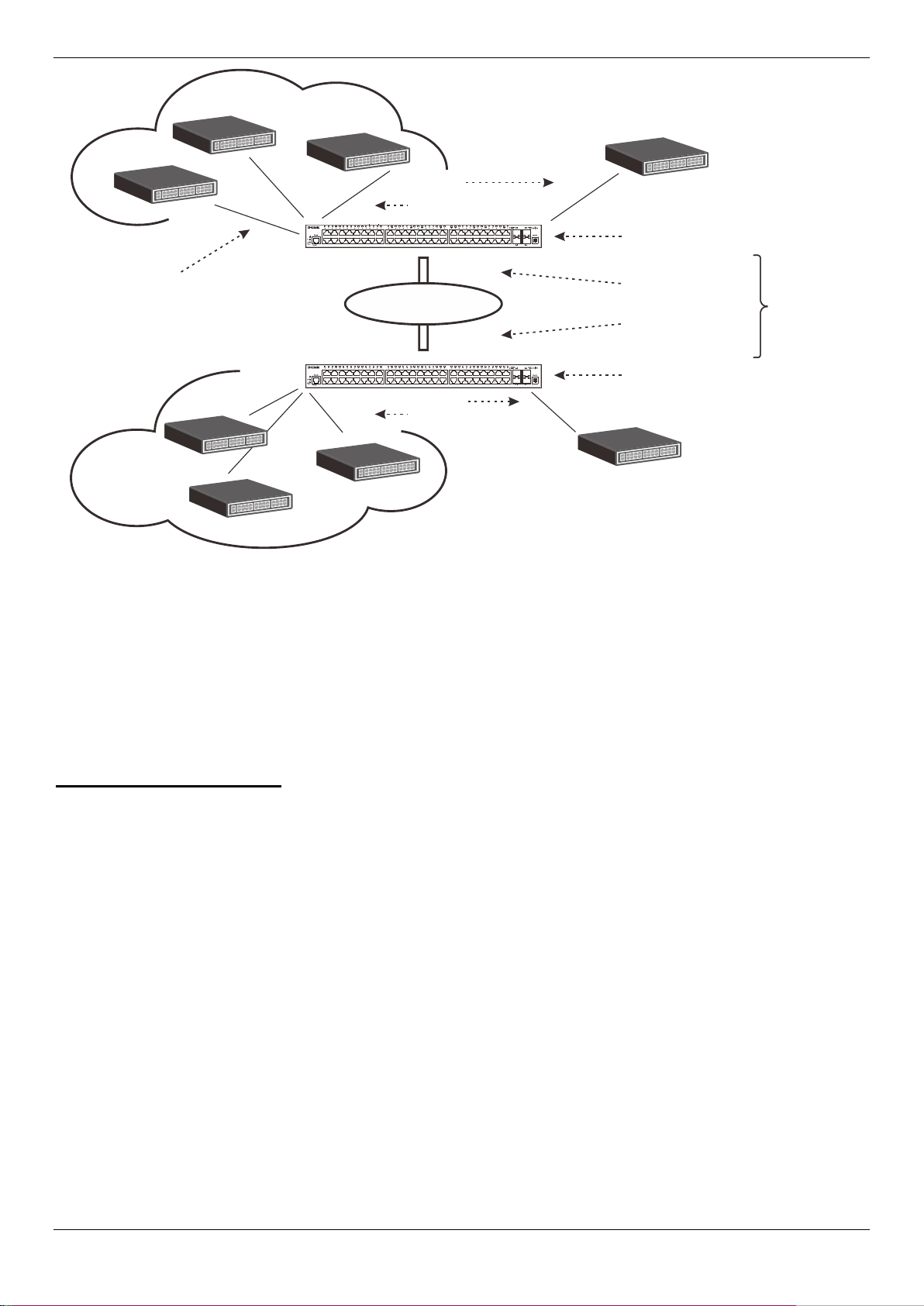
DGS-1510/ME Series Metro Ethernet Switch Web UI Reference Guide
Service Provider
Network
Customer A
VLANs
VID 1-100
Customer A
VLANs
VID 1-100
Customer B
VLANs
VID 1-100
Customer B
VLANs
VID 1-100
Service Provider
Access Network
Service Provider
Access Network
Uplink Ports
SPVLAN 100
CEVLAN10
SPVLAN 50
CEVLAN10
CEVLAN 11
CEVLAN
10
CEVLAN
10
Figure 4-18 QinQ example window
In this example, the Service Provider Ac cess Network switch (Provider edge switch) is the device creating and
configuring Double VLANs. Both CEVLANs (Cu st omer VLANs), 10 and 11, are tagged with the SPVID 100 on the
Service Provider Access Network and therefore belong to one VLAN on the Service Provider’s network, thus being a
member of two VLANs. In this way, the Cust om er can retain its normal VLAN and the Service Provider can
congregate multiple Customer VLANs withi n one SPVLAN, thus greatly regulating traffic and r outing on the Service
Provider switch. This information is then rout ed to the Service Provider’s main network and regarded there as one
VLAN, with one set of protocols and one routing behavior.
Regulations for Double VLANs
Some rules and regulations apply with the implementation of the Double VLAN procedure.
• All ports must be configured for the SPVID and i ts corresponding TPID on the Service Provider’s edge
switch.
• All ports must be configured as Access Ports or Uplink ports. Access ports can only be Ethernet ports
while Uplink ports must be Gigabit ports.
• Provider Edge switches must allow frames of at least 1522 bytes or more, due to the addition of the SPVID
tag.
• Access Ports must be an un-tagged po rt of the service provider VLANs. Uplink Ports must be a tagged port
of the service provider VLANs.
• The switch cannot have both double and normal VLANs co-existing. Once the change of VLAN is made, all
Access Control lists are cleared and must be reconfigured.
• Once Double VLANs are enabled, GVRP must be disabled.
• All packets sent from the CPU to the Access ports must be untagged.
• The following functions will not operate when the switch is in Double VLAN mode:
o Guest VLANs.
o Web-based Access Control.
o IP Multicast Routing.
o GVRP.
o All Regular 802.1Q VLAN functions.
74
Page 83

DGS-1510/ME Series Metro Ethernet Switch Web UI Reference Guide
QinQ State
Click to enable or disable the Q-in-Q state.
Inner TPID
Enter an Inner TPID in SP-VLAN tag here.
From Port / To Port
Use the drop-down menus to select a range of ports to use in the configuration.
Role
Port role in Q-in-Q mode, it can be UNI port or NNI po rt
to the PVID of the received port.
Outer TPID
Enter an Outer TPID in SP-VLAN tag here.
selected.
QinQ Settings
This window is used to configure the Q-in-Q parameters.
To view the following window, click L2 Features > QinQ > QinQ Settings, as show below:
Figure 4-19 QinQ Settings Window
The fields that can be configured are described below:
Parameter Description
Missdrop
Add Inner Tag
Click the Apply button to accept the changes made for each individual section.
This option enables or disables C-VLAN based SP-VLAN assignment miss drop. If
Missdrop is enabled, the packet that does not match any assignment rule in the Q-in-Q
profile will be dropped. If disabled, then the packet will be forwarded and will be assigned
Specifies that an Inner Tag will be added to the entry. By default the Disabled option is
VLAN Translation Settings
This window is used to add translation relations hi p between C-VLAN and SP-VLAN. On ingress at UNI port, the CVLAN tagged packets will be translated to S P-VLA N tagged packets by adding or replacing according the configured
75
Page 84
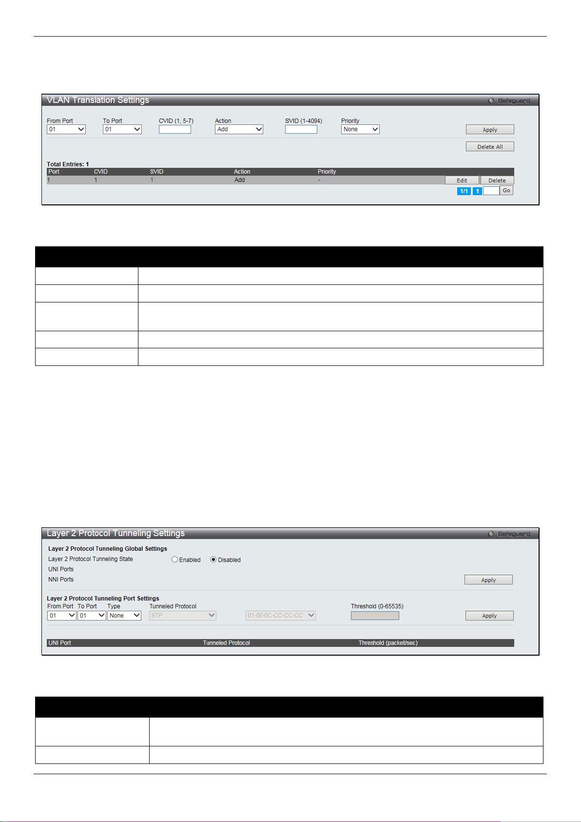
DGS-1510/ME Series Metro Ethernet Switch Web UI Reference Guide
From Port / To Port
Use the drop-down menus to select a range of ports to use in the configuration.
CVID (1, 5-7)
Enter the C-VLAN ID to match.
S-tag.
SVID (1-4094)
Enter the SP-VLAN ID.
Priority
Use the drop-down menu to select the priority of the s-tag.
Tunneling State
From Port / To Port
Use the drop-down menus to select a range of ports to use in the configuration.
rule. On egress at this port, the SP-VLAN tag will be recovered to C-VLAN tag or be striped. The priority will be t he
priority in the SP-VLAN tag if the inner priorit y flag is disabled for the receipt port.
To view the following window, click L2 Features > QinQ > VLAN Translation Settings, as show belo w:
Figure 4-20 VLAN Translation Settings Window
The fields that can be configured are described below:
Parameter Description
Action
Click the Apply button to accept the changes made for each individual section.
Click the Delete All button to remove all the entries listed.
Click the Edit button to re-configure the specific entry.
Click the Delete button to remove a specific entry.
Enter a page number and click the Go button to navigate to a specific page when multiple pages exist.
The action indicates to add an S-tag before a C-tag or to replace the original C-tag by an
Layer 2 Protocol Tunneling Settings
This window is used to configure Layer 2 protocol tunneling settings.
To view the following window, click L2 Features > Layer 2 Protocol tunneling Settings, as show below:
Figure 4-21 Layer 2 Protocol Tunneling Settings window
The fields that can be configured are described below:
Parameter Description
Layer 2 Protocol
Click to enable or disable the Layer 2 protocol tunneling state.
76
Page 85

DGS-1510/ME Series Metro Ethernet Switch Web UI Reference Guide
None - Disable tunnel on it.
All - All tunnel enabled Layer 2 protocols will be tunneled on the ports.
drop the PDU if the protocol’s threshold is exceeded.
Type
Tunneled Protocol
Threshold (0-65535)
Click the Apply button to accept the changes made for each individual section.
Select the type of the ports.
UNI - Specify the ports as UNI ports.
NNI - Specify the ports as NNI ports.
Select tunneled protocols on the UNI ports.
STP - Specify to use the STP protocol.
GVRP - Specify to use the GVRP protocol.
Protocol MAC - Specify the destination MAC address of the L2 prot ocol packets that will
tunneled on these UNI ports. The MAC address can be 01-00-0C-CC-CC-CC or 01-000C-CC-CC-CD.
Enter the drop threshold for packets-per-second accepted on the UNI ports. The ports
Spanning Tree
This Switch supports three versions of the Spanning Tree Protocol: 802.1D-1998 STP, 802.1D-2004 Rapid STP, and
802.1Q-2005 MSTP. 802.1D-1998 STP will be familiar to most networking professionals. However, since 802.1D-2004
RSTP and 802.1Q-2005 MSTP have been recently introduced to D-Link managed Ethernet switches, a brief
introduction to the technology is provided bel ow followed by a description of how to set up 802.1D-1998 STP, 802.1D2004 RSTP, and 802.1Q-2005 MSTP.
802.1Q-2005 MSTP
Multiple Spanning Tree Protocol, or MSTP, i s a st andard defined by the IEEE community that allows mult ipl e VLANs
to be mapped to a single spanning tree instance, which will provide multiple pathways across the network. Therefore,
these MSTP configurations will balance the traffic load, preventing wide scale disrupti ons when a single spanning tree
instance fails. This will allow for faster converg ences of new topologies for the failed instance. Fram es designated for
these VLANs will be processed quickly and complet ely throughout interconnected bridges utilizing any of the three
spanning tree protocols (STP, RSTP or MSTP).
An MSTI ID will classify these instances. M S T P wil l connect multiple spanning trees with a Common and Internal
Spanning Tree (CIST). The CIST will automaticall y determine each MSTP region, its maximum possible extent and
will appear as one virtual bridge that runs a single spanning tree. Consequentially, frames assi gned to different VLANs
will follow different data routes within adm i nist ratively established regions on the network, continuing to allow simple
and full processing of frames, regardless of adm i nistrative errors in defining VLANs and their respective spanning
trees.
Each switch utilizing the MSTP on a network will hav e a single MSTP configuration that will have the f ol l owing three
attributes:
1. A configuration name defined by an alphanumeri c st ring of up to 32 characters (defined in the MST
Configuration Identification window in the Configuration Name field).
2. A configuration revision number (named here as a Revision Level and found in the MST Configuration
Identification window) and;
3. A 4094-element table (defined here as a VID List in the MST Configuration Identification window), which
will associate each of the possible 4094 VLANs supported by the Switch for a given instance.
To utilize the MSTP function on the Switch, thre e st eps need to be taken:
1. The Switch must be set to the MSTP setting (foun d i n the STP Bridge Global Settings window in the STP
Version field)
2. The correct spanning tree priority for the M STP instance must be entered (defined here as a P riority in the
MSTI Config Information window when configuring MSTI ID settings).
3. VLANs that will be shared must be added to the MS T P Instance ID (defined here as a VID List in the MST
Configuration Identification window when configuring an MSTI ID settings).
77
Page 86

DGS-1510/ME Series Metro Ethernet Switch Web UI Reference Guide
Disabled
Disabled
Disabled
No
No
Discarding
Discarding
Blocking
No
No
Discarding
Discarding
Listening
No
No
Learning
Learning
Learning
No
Yes
Forwarding
Forwarding
Forwarding
Yes
Yes
802.1D-2004 Rapid Spanning Tree
The Switch implements three versions of t he S panning Tree Protocol, the Multiple Spanning Tree Protocol (MSTP) as
defined by the IEEE 802.1Q-2005, the Rapi d Spanning Tree Protocol (RSTP) as defined by the IEEE 802.1D-2004
specification and a version compatible wit h the IEEE 802.1D-1998 STP. RSTP can operate with legacy equipment
implementing IEEE 802.1D-1998; however the adv antages of using RSTP will be lost.
The IEEE 802.1D-2004 Rapid Spanning Tree Protocol (RSTP) evolved from the 802.1D-1998 STP standard. RSTP
was developed in order to overcome some limit ations of STP that impede the function of some recent switching
innovations, in particular, certain Layer 3 functions that are increasingly handled by Ethernet switches. The basic
function and much of the terminology is t he same as STP. Most of the settings configured for STP are also used for
RSTP. This section introduces some new Spanning Tree concepts and illustrates the main differen ces between the
two protocols.
Port Transition States
An essential difference between the three protocols is in the way ports transition to a forwarding state and in the way
this transition relates to the role of the port (f orwarding or not forwarding) in the topology. MSTP and RSTP combine
the transition states disabled, blocking and li st ening used in 802.1D-1998 and creates a single state Discarding. In
either case, ports do not forward packets. In the STP port transition states disabled, blocking or listening or in the
RSTP/MSTP port state discarding, there is no functional difference, the port is not active in the network topology.
Table 7-3 below compares how the three protocols differ regarding the port state transition.
All three protocols calculate a stable topology in the same way. Every segment will have a single path to the root
bridge. All bridges listen for BPDU packets. However, BPDU packets are sent more frequent ly - with every Hello
packet. BPDU packets are sent even if a BPDU packet was not received. Therefore, each link between bridges is
sensitive to the status of the link. Ultimat ely this difference results in faster detection of failed links, and thus faster
topology adjustment. A drawback of 802.1D-1998 is this absence of immediate feedback from adjacent bridges.
802.1Q-2005 MSTP 802.1D-2004 RSTP 802.1D-1998 STP Forwarding Learning
RSTP is capable of a more rapid transition to a forwarding state - it no longer relies on timer configurati ons - RSTP
compliant bridges are sensitive to feedback from ot her RSTP compliant bridge links. Ports do not need to wait for the
topology to stabilize before transitioning to a forwarding state. In order to allow this rapi d transition, the protocol
introduces two new variables: the edge port and the point-to-point (P2P) port.
Edge Port
The edge port is a configurable designat ion used for a port that is directly connected to a segment where a loop
cannot be created. An example would be a port conn ect ed directly to a single workstation. Ports that are designated
as edge ports transition to a forwarding state immediately without going through the listeni ng and learning states. An
edge port loses its status if it receives a BPDU pac ket, immediately becoming a normal spanning tree port.
P2P Port
A P2P port is also capable of rapid transition. P 2P ports may be used to connect to other bridges. Under RSTP/MSTP,
all ports operating in full-duplex mode are considered to be P2P ports, unless manually overridden t hrough
configuration.
802.1D-1998/802.1D-2004/802.1Q-2005 Compatibility
MSTP or RSTP can interoperate with legacy eq ui pment and is capable of automatically adjusting B P DU packets to
802.1D-1998 format when necessary. Howeve r, any segment using 802.1D-1998 STP will not benefit from the rapid
transition and rapid topology change detection of M STP or RSTP. The protocol also provides for a variable used for
migration in the event that legacy equipment on a segment is updated to use RSTP or MSTP.
78
Page 87
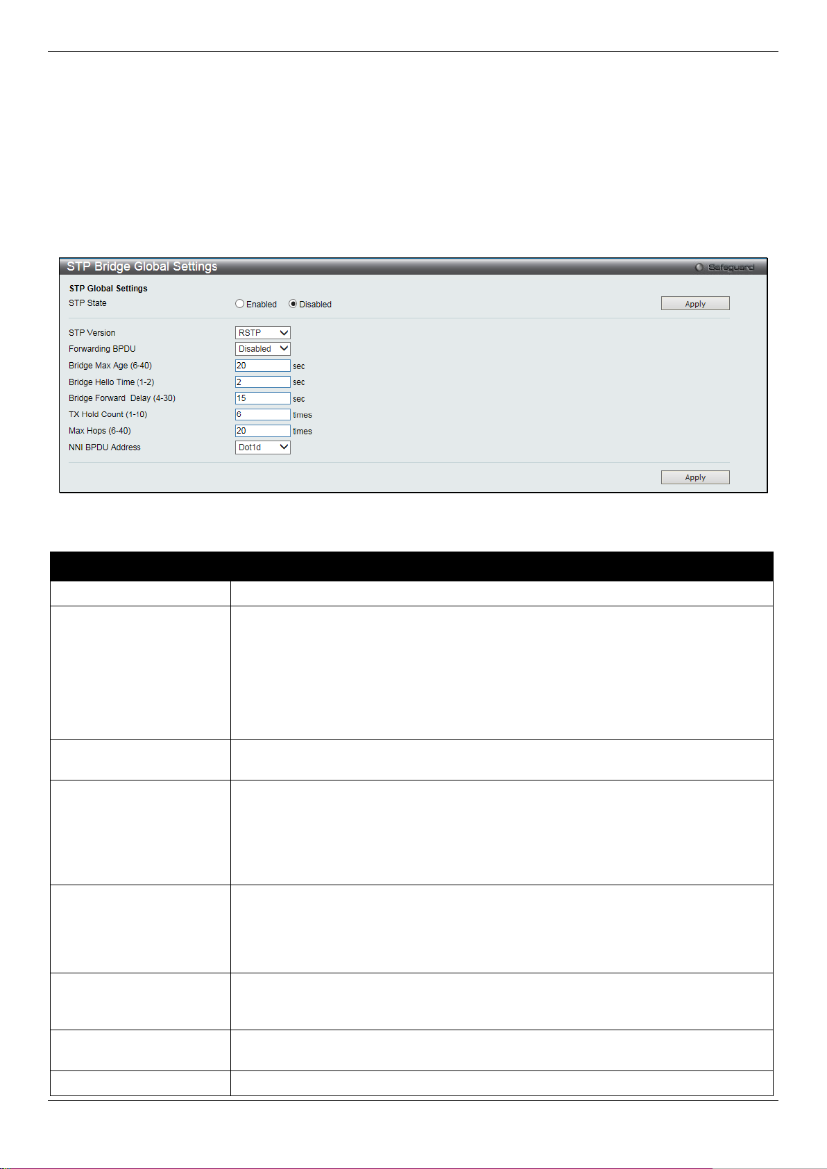
DGS-1510/ME Series Metro Ethernet Switch Web UI Reference Guide
STP State
Use the radio button to globally enable or disable STP.
globally on the Switch.
BPDU packets from other network devices. T he default is Disabled.
value is 20 seconds.
port basis. The default is 2 seconds.
The default is 15 seconds
can be specified from 1 to 10. The default is 6.
Max Hops (6-40)
Used to set the number of hops between devices in a spanning tree region before the
The Spanning Tree Protocol (STP) operates on two levels:
1. On the switch level, the settings are globally i m pl em ented.
2. On the port level, the settings are implemented on a per-user-defined group of ports basis.
STP Bridge Global Settings
On this page the user can configure the STP bridge global parameters.
To view the following window, click L2 Features > Spanning Tree > STP Bridge Global Settings, as show below:
Figure 4-22 STP Bridge Global Settings window
The fields that can be configured are described below:
Parameter Description
STP Version
Forwarding BPDU
Bridge Max Age (6-40)
Use the drop-down menu to choose the desired version of STP:
STP - Select this parameter to set the Spanning Tree P rotocol (STP) globally on the
switch.
RSTP - Select this parameter to set the Rapid Spanni ng Tree Protocol (RSTP)
globally on the Switch.
MSTP - Select this parameter to set the Multiple Spanning Tree Protocol (MSTP)
This field can be Enabled or Disabled. When Enabled, it allows the forwarding of STP
The Max Age may be set to ensure that old information does not endlessly circulate
through redundant paths in the network, prev enting the effective propagation of the
new information. Set by the Root Bridge, this value will aid in determining that the
Switch has spanning tree configuration values consistent with other devices on the
bridged LAN. The user may choose a time between 6 and 40 seconds. The default
Bridge Hello Time (1-2)
Bridge Forward Delay (4-
30)
Tx Hold Count (1-10)
The Hello Time can be set from 1 to 2 seconds. This is the i nterval between two
transmissions of BPDU packets sent by the Root B ri dge to tell all other switches that
it is indeed the Root Bridge. This field will only appear here when STP or RSTP is
selected for the STP Version. For MSTP, the Hello Time must be set on a port per
The Forward Delay can be from 4 to 30 seconds. Any port on the Switch spends this
time in the listening state while moving from the bl ocking state to the forwarding state.
Used to set the maximum number of Hello packets transmitted per interval. The count
79
Page 88
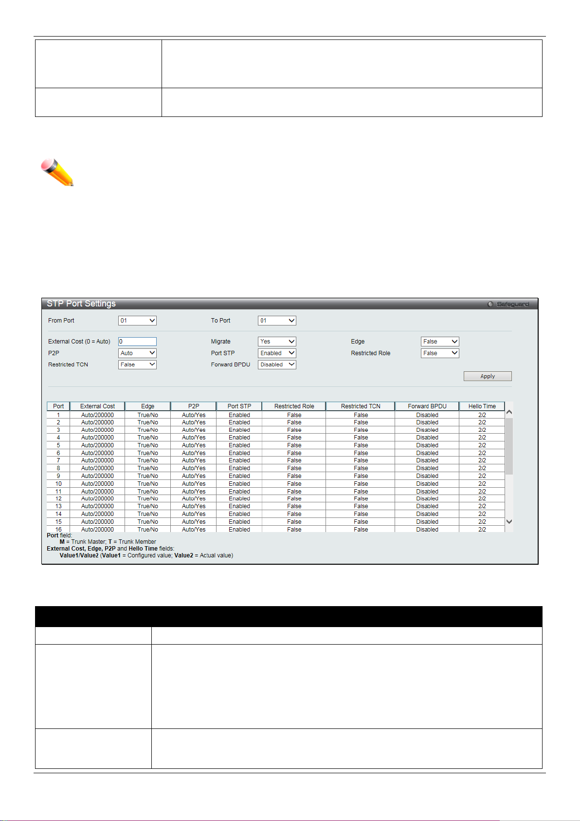
DGS-1510/ME Series Metro Ethernet Switch Web UI Reference Guide
BPDU (bridge protocol data unit) packet sent by the Switch will be discarded. Each
will age out. The user may set a hop count from 6 to 40. T he default is 20.
use 802.1D STP address or 802.1ad service provider STP address.
Bridge Max Age > 2 x (Bridge Hello Time + 1 second)
From Port / To Port
Select the starting and ending ports to be configured.
lower the number, the greater the probabilit y the port will be chosen to forward packets.
duplex. Like edge ports, P2P ports transition t o a forwarding state rapidly thus benefiting
switch on the hop count will reduce the hop count by one until the value reaches zero.
The Switch will then discard the BDPU packet and the information held for the port
NNI BPDU Address
Click the Apply button to accept the changes made for each individual section.
NOTE: The Bridge Hello Time cannot be longer than the Bridge Max Age. Otherwise, a configuration
error will occur. Observe the following formulas when setting the above parameters:
Bridge Max Age <= 2 x (Bridge Forward Delay - 1 sec ond)
Used to determine the BPDU protocol address for S TP in service provide site. It can
STP Port Settings
STP can be set up on a port per port basis. It is adv i sable to define an STP Group to correspond to a VLAN group of
ports.
To view the following window, click L2 Features > Spanning Tree > STP Port Settings, as show below:
Figure 4-23 STP Port Settings window
The fields that can be configured are described below:
Parameter Description
External Cost (0=Auto)
P2P
This defines a metric that indicates the relative cost of forwarding packets to the
specified port list. Port cost can be set aut om atically or as a metric value. The default
value is 0 (auto). Setting 0 for the external cost will automatically set the speed for
forwarding packets to the specified port(s) in the list for optimal efficiency. The default
port cost for a 100Mbps port is 200000 and the defaul t port cost for a Gigabit port is
20000. Enter a value between 1 and 200000000 to determine the External Cost. The
Choosing the True parameter indicates a point-to-point (P2P) shared link. P2P ports are
similar to edge ports; however they are restrict ed i n that a P2P port must operate in full
80
Page 89

DGS-1510/ME Series Metro Ethernet Switch Web UI Reference Guide
from RSTP. A P2P value of False indicates that the port cannot have P2P status. Auto
False. The default setting for this parameter is Auto.
and topology changes to other ports. The default i s False.
transmit RSTP BPDUs.
ports. The default is Enabled.
is disabled.
the Auto option is available.
True, the port will never be selected to be the Root port. The default is False.
running MSTP.
on the Switch.
MSTI ID (1-7)
Enter a number between 1 and 7 to set a new MSTI o n the Switch.
allows the port to have P2P status whenever pos sible and operate as if the P2P status
were True. If the port cannot maintain this status, (for example if the port is forced to
half-duplex operation) the P2P status changes t o operate as if the P2P value were
Restricted TCN
Migrate
Port STP
Forward BPDU
Edge
Restricted Role
Click the Apply button to accept the changes made.
Topology Change Notification is a simple B P DU t hat a bridge sends out to its root port
to signal a topology change. Restricted TCN can be toggled between True and False. If
set to True, this stops the port from propagating received topology change notifications
When operating in RSTP mode, selecting Yes f orces the port that has been selected to
This drop-down menu allows you to enable or disabl e STP for the selected group of
Use the drop-down menu to enable or disable the flooding of BPDU packets when STP
Choosing the True parameter designates the po rt as an edge port. Edge ports cannot
create loops, however an edge port can lose edge port status if a topology change
creates a potential for a loop. An edge port normall y should not receive BPDU packets.
If a BPDU packet is received, it automatically loses edge port status. Choosing the
False parameter indicates that the port does not have edge port status. Alternatively,
Use the drop-down menu to toggle Restricted Role between True and False. If set to
MST Configuration Identification
This window allows the user to configure a MS TI instance on the Switch. These settings will uniquel y identify a
multiple spanning tree instance set on the Switch. The Switch initially possesses one CIST, or Common Internal Spanning Tree, of which the user may modify the parameters for but cannot change the MSTI ID for, and cannot be deleted.
To view the following window, click L2 Features > Spanning Tree > MST Con figuration Identification, as show
below:
Figure 4-24 MST Configuration Identificat ion windo w
The fields that can be configured are described below:
Parameter Description
Configuration Name
Revision Level (0-65535)
This name uniquely identifies the MSTI (Multiple Spanning Tree Instance). If a
Configuration Name is not set, this field will sh ow the MAC address to the device
This value, along with the Configuration Name, identifies the MSTP region configured
81
Page 90

DGS-1510/ME Series Metro Ethernet Switch Web UI Reference Guide
with the VID List parameter.
Supported VIDs on the Switch range from ID num ber 1 to 4094.
MSTI ID
Enter the MSTI ID in this field. An entry of 0 denotes the CIST (default MSTI).
Priority
Enter the priority in this field. The available ran ge of values is from 0 to 61440.
Type
VID List
Click the Apply button to accept the changes made for each individual section.
Click the Edit button to re-configure the specific entry.
Click the Delete button to remove the specific entry.
This field allows the user to choose a desired method for altering the MSTI settings.
The user has two choices:
Add VID - Select this parameter to add VIDs to the MSTI ID, i n conjunctio n with the
VID List parameter.
Remove VID - Select this parameter to remove V IDs from the MSTI ID, in conjunction
This field is used to specify the VID range from co nfigured VLANs set on the Switch.
STP Instance Settings
This window displays MSTIs currently set on the Switch and allows users to change the Priorit y of the MSTIs.
To view the following window, click L2 Features > Spanning Tree > STP Instance Settings, as show below:
Figure 4-25STP Instance Settings window
The fields that can be configured are described below:
Parameter Description
Click the Apply button to accept the changes made.
Click the Edit button to re-configure the specific entry.
Click the View button to display the information of the specific entry.
MSTP Port Information
This window displays the current MSTI conf iguration information and can be used to update the port configuration for
an MSTI ID. If a loop occurs, the MSTP function wil l use the port priority to select an interface to put i nto the
forwarding state. Set a higher priority value f or interfaces to be selected for forwarding first. In i nst ances where the
priority value is identical, the MSTP function wil l i m pl ement the lowest MAC address into the forwarding state and
other interfaces will be blocked. Remember that lower priority values mean higher priorities f or forwarding packets.
To view the following window, click L2 Features > Spanning Tree > MSTP P ort Information, as show below:
82
Page 91

DGS-1510/ME Series Metro Ethernet Switch Web UI Reference Guide
Port
Select the port you want to configure.
of 0 in this field denotes the CIST (default MSTI ).
parameter will set the quickest route auto m atically and optimally for an interface.
priority.
Figure 4-26 MSTP Port Information window
The fields that can be configured are described below:
Parameter Description
Instance ID
Internal Path Cost (1-
200000000)
Priority
Click the Find button to locate a specific entry based on the information entered.
Click the Apply button to accept the changes made.
Click the Edit button to re-configure the specific entry.
The MSTI ID of the instance to be configured. Enter a value between 0 and 15. An entry
This parameter is set to represent the relative cost of forwarding packets to specified
ports when an interface is selected within an S T P i nstance. Selecting this parameter with
a value in the range of 1 to 200000000 will set the quickest route when a loop occurs. A
lower Internal cost represents a quicker transmission. Selecting 0 (zero) for this
Enter a value between 0 and 240 to set the prio ri ty for the port interface. A higher priority
will designate the interface to forward packets f i rst. A lower number denotes a higher
Link Aggregation
Understanding Port Trunk Groups
Port trunk groups are used to combine a number of ports together to make a single high-bandwidth data pipeline. The
number of port trunk groups, supported by t he S witch, is equal to half of the total physical ports on the Switch. Each
port trunk group can have two to eight physical ports assigned to each g roup.
83
Page 92

DGS-1510/ME Series Metro Ethernet Switch Web UI Reference Guide
4-27 Example of Port Trunk Group
The Switch treats all ports in a trunk group as a single port. Data transmitted to a specific host (dest ination address)
will always be transmitted over the same port in a t runk group. This allows packets in a data stream t o arrive in the
same order they were sent.
Link aggregation allows several ports to be grouped together and to act as a single link. This gives a ba ndwidth that is
a multiple of a single link's bandwidth.
Link aggregation is most commonly used to li nk a bandwidth intensive network device or devices, su ch as a server, to
the backbone of a network.
All of the ports in the group must be members of t he same VLAN, and their STP status, static multicast , traffic
segmentation and 802.1p default priority conf i gurations must be identical. Port locking, port mirroring, traffic control,
and 802.1X must not be enabled on the trunk group. Further, the LACP aggregated links must all be of the same
speed and should be configured as full duplex.
The Master Port of the group is to be configure d by the user, and all configuration options, includi ng the VLAN
configuration that can be applied to the Maste r P ort, are applied to the entire link aggregation group.
Load balancing is automatically applied to the port s in the aggregated group, and a link failure within the group causes
the network traffic to be directed to the remaining links in the group.
84
Page 93

DGS-1510/ME Series Metro Ethernet Switch Web UI Reference Guide
choose from are MAC Source Dest, IP Sour ce Dest and Lay4 Source Dest.
Group ID
Select an ID number for the group.
Control Protocol). LACP allows for the automatic detection of links in a Port Trunking Group.
Master Port
Choose the Master Port for the trunk group using the drop-down menu.
control.
group.
Active Ports
Show the ports that are currently forwarding packets.
The Spanning Tree Protocol will treat a link aggregation group as a single link, on the switch level. On the port level,
the STP will use the port parameters of the Master Port in the calculation of port cost and in det erm i ning the state of
the link aggregation group. If two redundant link aggregation groups are configured on the Switch, STP will block one
entire group; in the same way STP will block a sin gl e port that has a redundant link.
NOTE: If any ports within the trunk group become disconnected, packets intended for the disconnected
port will be load shared among the other linked port s of the link aggregation group.
Port Trunking Settings
On this page the user can configure the port trun k s ettings for the switch.
To view the following window, click L2 Features > Link Aggregation > Port Trunking Settings, as show below:
Figure 4-28 Port Trunking Settings window
The fields that can be configured or displayed are described below:
Parameter Description
Algorithm
Type
State
Member Ports
Click the Apply button to accept the changes made.
Click the Clear All button to clear out all the information entered.
Click the Add button to add a new entry based on the information ent ered.
This is the traffic hash algorithm among the ports of the link aggregation group. Options to
This drop-down menu allows users to select between Static and LACP (Link Aggregation
Use the drop-down menu to toggle between Enabled and Disabled. This is used to turn a port
trunking group on or off. This is useful for diag nostics, to quickly isolate a bandwidth intensive
network device or to have an absolute backup ag gregation group that is not under automatic
Choose the members of a trunked group. Up to eight ports per group can be assigned to a
NOTE: The maximum number of ports that can be configured in one Static Trunk or LACP Group are 8
ports.
85
Page 94

DGS-1510/ME Series Metro Ethernet Switch Web UI Reference Guide
From Port / To Port
A consecutive group of ports may be configure d st arting with the selected port.
dynamically, one end of the connection must have "active" LACP ports (see above).
LACP Port Settings
In conjunction with the Trunking window, users can create port trunking groups on the Switch. Using the following
window, the user may set which ports will be active and passive in processing and sending LACP control frames.
To view the following window, click L2 Features > Link Aggregation > LACP P ort S et ti ngs, as show below:
Figure 4-29 LACP Port Settings window
The fields that can be configured are described below:
Parameter Description
Activity
Click the Apply button to accept the changes made.
Active - Active LACP ports are capable of processing and se ndi ng LACP control frames.
This allows LACP compliant devices to negotiat e the aggregated link so the group may be
changed dynamically as needs require. I n order to utilize the ability to change an
aggregated port group, that is, to add or subtr act ports from the group, at least one of the
participating devices must designate LACP ports as active. Both devices must support
LACP.
Passive - LACP ports that are designat ed as passive cannot initially send LACP control
frames. In order to allow the linked port group to negotiate adjustments and make changes
86
Page 95

DGS-1510/ME Series Metro Ethernet Switch Web UI Reference Guide
unicast MAC address resides.
resides.
address.
Port, enter the port number in the field.
FDB
Static FDB Settings
Unicast Static FDB Settings
Users can set up static unicast forwarding on the Switch.
To view the following window, click L2 Features > FDB > Static FDB Settings > Unicast Static FDB Settings, as
show below:
Figure 4-30 Unicast Static FDB Settings window
The fields that can be configured are described below:
Parameter Description
VLAN Name
VLAN List
MAC Address
Port / Drop
Click the Apply button to accept the changes made.
Click the Delete button to remove the specific entry.
Enter a page number and click the Go button to navigate to a specific page when multiple pages exist.
Click the radio button and enter the VLAN name of the VLAN on which the associated
Click the radio button and enter a list of VLA N on which the associated unicast MAC address
The MAC address to which packets will be statically forwarded. This must be a unicast MAC
Allows the selection of the port number on which t he MAC address entered above resides
This option could also drop the MAC address from the unicast static FDB. When selecting
Multicast Static FDB Settings
Users can set up static multicast forwarding on the Switch.
To view the following window, click L2 Features > FDB > Static FDB Settings > Multicast Static FDB Settings, as
show below:
Figure 4-31 Multicast Static FDB Settings window
87
Page 96

DGS-1510/ME Series Metro Ethernet Switch Web UI Reference Guide
VID
The VLAN ID of the VLAN the corresponding MAC a ddress belongs to.
MAC address.
select all the ports.
The fields that can be configured are described bel ow:
Parameter Description
Multicast MAC Address
Port
Click the Clear All button to clear out all the information entered.
Click the Apply button to accept the changes made.
The static destination MAC address of the mul ticast packets. This must be a multicast
Allows the selection of ports that will be members of the static multicast group and
ports that are either forbidden from joinin g dynamically, or that can join the multicast
group dynamically, using GMRP. The options are:
None - No restrictions on the port dynamically joining the multi cast group. When None
is chosen, the port will not be a member of the St atic Multicast Group. Click the All
button to select all the ports.
Egress - The port is a static member of the multicast group. Click the All button to
MAC Notification Settings
MAC Notification is used to monitor MAC addresses learned and entered into the forwarding databas e. This wind ow
allows you to globally set MAC notification on t he S witch. Users can set MAC notification for indiv idual ports on the
Switch.
To view the following window, click L2 Features > FDB > MAC Notification Settings, as show below:
Figure 4-32 MAC Notification Settings window
The fields that can be configured are described below:
88
Page 97
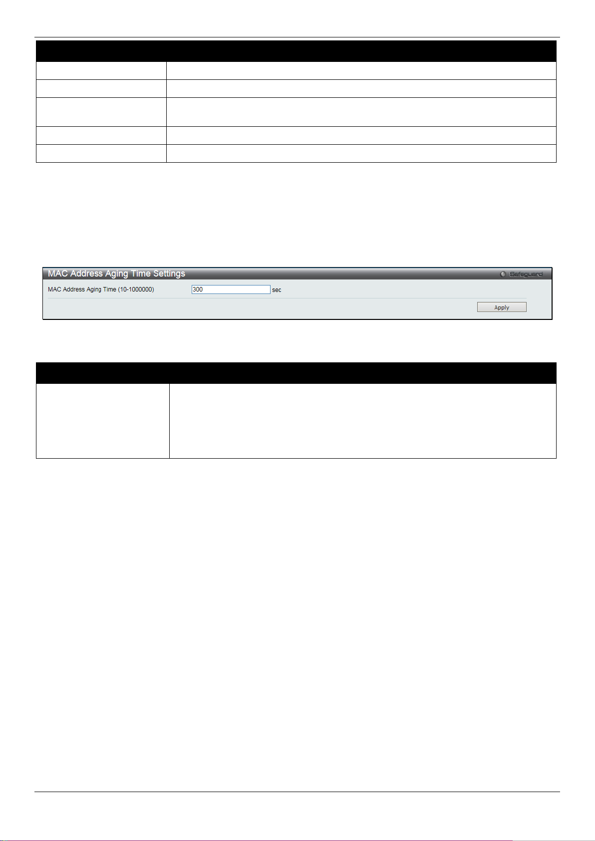
DGS-1510/ME Series Metro Ethernet Switch Web UI Reference Guide
State
Enable or disable MAC notification globally on the Switch
Interval (1-2147483647)
The time in seconds between notifications. Value range to use is 1 to 2147483647.
500 entries can be specified.
From Port / To Port
Select the starting and ending ports for MAC notification.
State
Enable MAC Notification for the ports selected u sing the drop-down menu.
seconds.
Parameter Description
History Size (1-500)
Click the Apply button to accept the changes made for each individual section.
The maximum number of entries listed in the hist ory log used for notification. Up to
MAC Address Aging Time Settings
Users can configure the MAC Address aging time on t he Switch.
To view the following window, click L2 Features > FDB > MAC Address Aging Time Settings, as show below:
Figure 4-33 MAC Address Aging Time Settings window
The fields that can be configured are described bel ow:
Parameter Description
MAC Address Aging
Time (10-1000000)
This field specify the length of time a learned MAC Address will remain in the
forwarding table without being accessed (that is, how long a learned MAC Address is
allowed to remain idle). To change this option, t ype in a different value representing
the MAC address’ age-out time in seconds. The MA C Address Aging Time can be
set to any value between 10 and 1000000 seconds. The default setting is 300
Click the Apply button to accept the changes made.
MAC Address Table
This allows the Switch's MAC address forwarding table to be viewed. When the Switch learns an as sociation between
a MAC address, VLAN and a port number, it makes an entry into its forwarding table. These entries are then used to
forward packets through the Switch.
To view the following window, click L2 Features > FDB > MAC Address Table, as show below:
89
Page 98

DGS-1510/ME Series Metro Ethernet Switch Web UI Reference Guide
Port
The port to which the MAC address below corresponds.
VLAN Name
Enter a VLAN Name for the forwarding table to be browsed by.
VID List
Enter a list of VLAN IDs for the forwarding table to be browsed by.
MAC Address
Enter a MAC address for the forwarding table t o be browsed by.
Security
Tick the check box to display the FDB entries that are created by the security module.
Port
Select the port number to use for this configurat i on.
Figure 4-34 MAC Address Table window
The fields that can be configured are described below:
Parameter Description
Click the Find button to locate a specific entry based on the inf ormation entered.
Click the Clear Dynamic Entries button to delete all dynamic entries of the address table.
Click the View All Entries button to display all the existing entries.
Click the Clear All Entries button to remove all the entries listed in the table.
Click the Add to Static MAC table button t o add the specific entry to the Static MAC table.
Enter a page number and click the Go button to navigate to a specific page when multiple pages exist.
ARP & FDB Table
On this page the user can find the ARP and FDB tabl e parameters.
To view the following window, click L2 Features > FDB > ARP & FDB Table, as show below:
Figure 4-35 ARP & FDB Table window
The fields that can be configured are described below:
Parameter Description
90
Page 99

DGS-1510/ME Series Metro Ethernet Switch Web UI Reference Guide
MAC Address
Enter the MAC address to use for this configurat i on.
IP Address
Enter the IP address the use for this configurati on.
IGMP Snooping State
Click to enable or disable the IGMP Snooping state.
Value (1-1024)
Click the Find by Port button to locate a specific entry based on the port number selected.
Click the Find by MAC button to locate a specific entry based on the MA C address entered.
Click the Find by IP Address button to locate a specific entry based on the IP address entered.
Click the View All Entries button to display all the existing entries.
Click the Add to IP MAC Port Binding Table to add the specific entry to the IMPB Entry Settings window.
L2 Multicast Control
IGMP Snooping
Internet Group Management Protocol (IGMP) snooping allows the Switch to recognize IGMP queries and reports sent
between network stations or devices and an I G M P host . When enabled for IGMP snooping, the Switch ca n open or
close a port to a specific device based on IGMP messages passing through the Switch.
IGMP Snooping Settings
In order to use IGMP Snooping it must first be enabled for the entire Switch under IGMP Snooping Global Settings at
the top of the window. You may then fine-tune the set tings for each VLAN by clicking the corresponding Edit button.
When enabled for IGMP snooping, the Switch can open or close a port to a specific multicast group member based on
IGMP messages sent from the device to the IGMP host or vice versa. The Switch monitors IG M P m essages and
discontinues forwarding multicast packet s when there are no longer hosts requesting that they continue.
To view the following window, click L2 Features > L2 Multicast Control > IGMP Snooping > IGMP Snooping
Settings, as show below:
Figure 4-36 IGMP Snooping Settings window
The fields that can be configured are described below:
Parameter Description
Max Learned Entry
Click the Apply button to accept the changes made for each individual section.
Click the Edit button to configure the IGMP Snooping Parameters Settings.
Click the Modify Router Port link to configure the IGMP S noopi ng Router Port Settings.
Enter a page number and click the Go button to navigate to a specific page when multiple pages exist.
After clicking the Edit button, the following page will appear:
Enter the maximum learning entry value.
91
Page 100

DGS-1510/ME Series Metro Ethernet Switch Web UI Reference Guide
default setting is 125 seconds..
25)
setting is 10 seconds.
default, the robustness variable is set to 2.
member of a group.
Time (1-65535)
Querier State
Specify to enable or disable the querier state.
is immediately removed when the system receive the IGMP leave message.
multicast-routing protocol packet, the port will be timed out as a router port.
into one report only before sending to the router port.
State
Aged Out
Version
Specify the version of the IGMP general query sent by the Switch.
Figure 4-37 IGMP Snooping Parameters Settings windo w
The fields that can be configured are described below:
Parameter Description
Query Interval (1-65535)
Max Response Time (1-
Robustness Value (1-7)
Last Member Query
Interval (1-25)
Data Drive Group Expiry
Fast Leave
State
Specify the amount of time in seconds between gen eral query transmissions. The
Specify the maximum time in seconds to wait for reports from members. The default
Provides fine-tuning to allow for expected packet loss on a subnet. The value of the
robustness value is used in calculating the following IGMP message intervals: By
Specify the maximum amount of time between g roup-specific query messages,
including those sent in response to leave-group messages. You might lower this
interval to reduce the amount of time it takes a rout er to detect the loss of the last
Specify the data driven group lifetime in secon ds.
Enable or disable the IGMP snooping fast leave function. If enabled, the membership
If the state is Enabled, it allows the Switch to be selected as an IGMP querier (sends
IGMP query packets). It the state is disabled, then the switch cannot play the role as
a querier.
NOTE: that if the Layer 3 router connected to the switch provides only the IGMP
proxy function but does not provide the multicast routing f unct i on, then this state must
be configured as disabled. Otherwise, if the Layer 3 router is not selected as the
querier, it will not send the IGMP query packet. S i nce it will not also send the
Report Suppression
Data Driven Learning
Data Drive Learning
When enabled, multiple IGMP reports or l eave for a specific (S, G) will be integrated
Specify to enable or disable the data driven learni ng state.
Specify to enable or disable the data drive learnin g aged out option.
Click the Apply button to accept the changes made.
Click the <<Back button to discard the changes made and return to t he previous page.
After clicking the Modify Router Port link, the following page will appear:
92
 Loading...