

Page 1

DES-3216 10/100 Auto Negotiation
Switch
User’s Guide
Rev. A1 (December, 1998)
6DES3216..02
Printed In Taiwan
RECYCLABLE
Page 2

D-Link Limited Warranty
Hardware:
D-Link warrants i ts hardware produc ts to be free fr om defects in w orkmanship and m aterials, under normal use and service, for the fol lowing
periods measured from date of purchase from D-Link or its authorized Reseller:
Product Type Warranty Period
Complete Products One year
Spare parts and spare kits 90 days
Your dealer, or your nearest D-Link offic e, c an ad vise whe ther a l ong er peri od of war rant y ap pl ies to your pur chas e, and i f so, can pr o vide you a
separate certificate of supplemental warranty.
The one-year peri od of warranty o n complete produc ts (or suc h longer period of war ranty as ma y be offered as to your purc hase) appl ies on
condition that the pro duct’s Regis tration Card is filled out and retur ned to a D-Link office within ninety (90) days of purchas e. A list of D-Li nk
offices is provided at the back of this manual, together with a copy of the Re gistration Card. Fai ling such timely registr ation of purchase, the
warranty period shall be limited to ninety (90) days.
If the product proves defective within the applicable warranty period, D-Link will provide repair or replacement of the product. D-Link s hall ha ve
the sole discretion whether to repair or replace, and replacement produc t may be new or reconditioned. Replacement produc t shall be of
equivalent or better s pec ifi c ations , relati ve to the defec tive product, but need no t be i den tic al . Any product or p ar t repai red b y D-Li nk pursuant to
this warranty shall have a warranty p eriod of not les s than 90 da ys, from date of such r epair, i rrespecti ve of any earlier expiration of or iginal
warranty period. When D-Link provides replacement, then the defective product becomes the property of D-Link.
Warranty service may be obtained by contacting a D-Link office within the applicable warranty period, and requesting a Return Material
Authorization (RMA) number. If a Registrati on Card for the product in questi on has not been retur ned to D-Li nk, then a pro of of p urchase ( such
as a copy of the da ted p urc hase i nvoic e) m ust be pr ovided. If handl i ng of warr ant y cor rec ti on i s r equi red under s peci al circ ums tances , you may
request special procedure at the time of requesting an RMA number.
After an RMA number is issued, the defective product must be packaged securely in the original or other suitable shipping package to ensure that
it will not be damaged in tr ansi t, and t he RMA number mus t be pr om inentl y m arked on the o uts ide of the p ac kag e. T he pac kage m us t be m ail ed
or otherwise shipped to D-Link with all costs of mailing/shipping/insurance prepaid: D-Link will ordinarily reimburse for mailing/shipping/insurance
expenses incurr ed for r eturn of d efec tive product in ac cor dance w ith thi s warr anty. D-Li nk shal l ne ver be res pons ibl e for an y s oftware, firm ware,
information, data contained in, stored on or integrated with any product returned to D-Link pursuant to this warranty.
Any package returned to D-Link without an RMA number will be rejected and shipped bac k to you at your e xpense, a nd D- Link res erves the right
in such case to levy a reasonable handling charge in addition to mailing or shipping costs.
Software:
W arrant y s ervice f or softw ar e produc ts m a y be obtained by c ontacting a D -Link of f ice w it hi n the ap pl icable warr anty per i od . A
list of D-Li nk offices is provided at the b ac k of t his m anual, t og et her wit h a copy of th e Regis tration C ar d . If a R egis tration Card
for the product in qu estion has not b een return ed to a D-Li nk office, then a proof of purchas e (such as the dated purchase
invoice) must be provided when requesting warranty service. The term “purchase” in this software warranty refers to the
purchase transaction and resulting license to use such software.
D-Link warran ts that its s oftw are pr oducts will p erfor m in su bstant ial conf orm ance with th e applic able product d ocum entation
provid ed by D-Link w ith such soft ware produc t, for a peri od of ninety (90 ) days from th e date of purc hase f rom D-Lin k or its
Author iz ed Reseller . D-Lin k w arrants t h e m ag netic m edia, on wh ic h D- L i nk provides its s of tw ar e product , ag ainst failure during
the same warranty period. This warranty applies to purchased software, and to replacement s oftware provided by D-Link
pursuant to this warranty, but shall not apply to any update or replacement which may be provided for download via the
Intern et, or t o any updat e whic h m a y ot h er wise be provi d ed f r ee of charge.
ii
Page 3

D-Link’s sole ob ligation under this software w arranty shal l be to replac e any defective software produc t with produc t that
subst anti al ly confor ms to D- Li nk ’s applicabl e product d oc um en tation. You assume r es ponsibil ity f or the selec t i on of appropr i ate
application and system/platform software and associated reference materials. D-Link makes no warranty that its software
products will wor k in combin ation wit h any har dware, or any applic ation or s ystem p latfor m soft ware pr oduc t provi ded by any
third party, except those expressly d es ignated in D-Link’s appl icable product documentation as being c ompatible. D-Link’s
obligation under this warranty shall be a reasonable effort to provide compatibility, but D-Link shall have no obligation to
provid e compat i bi lity wh en ther e is f ault in t h e third-party h ar d w are or s oft w are. D-L in k m ak es no w arranty that oper ation of its
softwar e produc ts will be un int err upt ed or abs olut ely er ror- fr ee, and no warr an ty t hat all def ects i n t he s oftw are p r oduct, withi n
or without the scope of D-Link’s applicable product documentation, will be corrected.
D-Link Offices for Registration and Warranty Service:
The product’s R egistration c ard, provided at the bac k of this m anual, must be s ent to a D-Link offic e. To obtain an R MA number for warranty
service as to a hardware product, or to obtain warranty service as to a software product, contact the D-Link office nearest to you.
D-Link Offices to Contact for Warranty Service:
To mail your Registration Card, or to obtain an RMA number or warranty service, see the following address:
In North, Central, and South America:
D-Link Systems Inc.
53 Discovery Drive, Irvine CA 92618
Tel. (1)714-788-0805 Fax (1)714-753-7033
In Europe and Israel:
D-Link Europe
Denmark House, Staples Corner, The Broadway, London NW9 7BW, U.K.
Tel. (44)181-203-9900 Fax (44)181-203-6915
In the Middle East (except Israel), Asia, Oceania and Africa:
D-Link Corporation
No. 233-2, 2
TEL. (886)2-916-1600
Trademarks
Copyright 1998 D-Link Corporation.
D-Link © is a registered trademark of D-Link Corporation/D-Link Systems, Inc.
All rights reserved, contents may be revised without prior notice.
FlexSWITCH
Ethernet is a trademark of Xerox Corporation.
Microsoft Windows is a trademark of Microsoft Corporation.
VT100 is a trademark of Digital Equipment Corporation.
All other trademarks belong to their respective proprietors.
nd
F. Pao Chiao Road, Hsin Tien Taipei, Taiwan
TM
is a trademark of D-Link Systems, Inc.
Copyright Statement
iii
Page 4
No part of this publication may be reproduced in any form or by any means or used to make any derivative such as translation, transformation, or
adaptation without permission from D-Link Corporation/D-Link Systems Inc., as stipulated by the United States Copyright Act of 1976.
FCC Warning
This equipment has been tested and fou nd to com pl y with the limi ts for a C lass A digi tal device, pursuant t o Part 15 of the FCC Rules. These
limits are desi gned to pr o vide reas onabl e protec ti on ag ai nst har m ful i nter ferenc e when the eq ui pm ent i s operated i n a c om m erci al environment.
This equipment generates, uses, and can radi ate r adio fr e quency energy and, i f not i nstal l ed and us ed in ac c ordanc e wi th this us er ’s gui de, m a y
cause harmful i nterference to r adio comm unications . Operati on of this equi pment in a r esidenti al area i s likely to cause h armful interfer ence in
which case the user will be required to correct the interference at his own expense.
CE Mark Warning
This is a Class A product. In a domestic environment, this product may cause radio interference in which case the user may be
required to take adequate measures.
iv
Page 5

Wichtige Sicherheitshinweise
Bitte lesen Sie sich diese Hinweise sorgfältig durch.
Heben Sie diese Anleitung für den spätern Gebrauch auf.
Vor jedem Reinigen ist das Gerät vom Stromnetz zu trennen. Vervenden Sie keine Flüssig- oder Aerosolreiniger. Am besten dient ein
angefeuchtetes Tuch zur Reinigung.
Um eine Beschädigung des Gerätes zu vermeiden sollten Sie nur Zubehörteile verwenden, die vom Hersteller zugelassen sind.
Das Gerät is vor Feuchtigkeit zu schützen.
Bei der Aufstellung des Ger ätes is t auf sic hern Stand zu achte n. Ein Kippen oder Fall en könnte Verlet zungen her vorrufen. V erwende n Sie nur
sichere Standorte und beachten Sie die Aufstellhinweise des Herstellers.
Die Belüftungsöffnungen dienen zur Luftzirkulation die das Gerät vor Überhitzung schützt. Sorgen Sie dafür, daß diese Öffnungen nicht
abgedeckt werden.
Beachten Sie beim Anschluß an das Stromnetz die Anschlußwerte.
Die Netzanschlußsteckdose muß aus Gründen der elektrischen Sicherheit einen Schutzleiterkontakt haben.
Verlegen Sie die Netzanschlußleitung so, daß niemand darüber fallen kann. Es sollete auch nichts auf der Leitung abgestellt werden.
Alle Hinweise und Warnungen die sich am Geräten befinden sind zu beachten.
Wird das Gerät über einen länger en Zeitraum ni cht benutzt, sollten Si e es vom Strom netz trennen. Som it wird im Falle einer Überspannung
eine Beschädigung vermieden.
Durch die Lüftungsöffnungen dürfen niemals Gegenstände oder Flüssigkeiten in das Gerät gelangen. Dies könnte einen Brand bzw.
Elektrischen Schlag auslösen.
Öffnen Sie niemals das Gerät. Das Gerät darf aus Gründen der elektrischen Sicherheit nur von authorisiertem Servicepersonal geöffnet werden.
Wenn folgende Situationen auftreten ist das Gerät vom Stromnetz zu trennen und von einerqualifizierten Servicestelle zu überprüfen:
Netzkabel oder Netzstecker sint beschädigt.
Flüssigkeit ist in das Gerät eingedrungen.
Das Gerät war Feuchtigkeit ausgesetzt.
Wenn das Gerät nicht der Bedienungsanleitung ensprechend funktioniert oder Sie mit Hilfe dieser Anleitung keine Verbesserung erzielen.
Das Gerät ist gefallen und/oder das Gehäuse ist beschädigt.
Wenn das Gerät deutliche Anzeichen eines Defektes aufweist.
Bei Reparaturen dürfen nur Orginaler satzteile bzw. den Orginalteilen entsprec hende Teile verwendet werd en. Der Einsatz von ungeeigneten
Ersatzteilen kann eine weitere Beschädigung hervorrufen.
Wenden Sie s ich mit allen Fragen die Ser vice und Repartur betreff en an Ihren Ser vicepartner. Somit s tellen Sie die Betriebssic herheit des
Gerätes sicher.
v
Page 6

Table of Contents
Table o f Contents.................................................................................................................vi
About This Guide..................................................................................................................1
Audience........................................................................................................................... 1
Organization...................................................................................................................... 1
1............................................................................................................................................2
Introduction...........................................................................................................................2
Features.............................................................................................................................2
Front Panel........................................................................................................................3
Rear Panel.........................................................................................................................3
Management Methods.......................................................................................................4
Local Console Management ..........................................................................................4
Telnet Management.......................................................................................................4
D-View/ SNMP Management........................................................................................4
Updating Fir mware............................................................................................................4
2............................................................................................................................................5
Installing the DES-3216........................................................................................................5
Installation Options ...........................................................................................................5
Power On..........................................................................................................................6
3............................................................................................................................................7
Connecting the DES-3216 to the Net work.............................................................................7
Cable Specifications.......................................................................................................... 7
Ports..................................................................................................................................9
MDI-X Po rt...................................................................................................................9
RS-232 Port...................................................................................................................9
DES-3216 to DES-3216 Connectio n ..................................................................................9
Connecting the DES-3216 to the DES-5024 and Hubs....................................................... 9
4..........................................................................................................................................10
LEDs...................................................................................................................................10
DES-3216 LED Panel......................................................................................................11
5..........................................................................................................................................13
Table of Contents
vi
Page 7

Managing t he DES-3216.....................................................................................................13
Local Console Management ............................................................................................13
Telnet..............................................................................................................................14
Log In.............................................................................................................................15
Help Message ..................................................................................................................16
Panel Conventions ...........................................................................................................17
Console Program .............................................................................................................18
System Configuration..................................................................................................18
User Account Management..........................................................................................18
Switch Port 1-8, 9-16 Configuratio n ............................................................................18
Spanning Tree Configuration.......................................................................................18
SNMP Management Co nfiguration ..............................................................................19
VLAN Port Management.............................................................................................19
Trunking Port Management.........................................................................................19
System Configuration Menu............................................................................................20
System Information Menu ...........................................................................................21
System Reset............................................................................................................... 23
Factory Reset............................................................................................................... 24
System Rate Control.................................................................................................... 26
Software Update Menu................................................................................................28
User Account Management .............................................................................................31
User Account Change Menu........................................................................................31
Create New User......................................................................................................... 31
Delet e Users................................................................................................................33
Change Password ........................................................................................................34
Switch Port Configuration...............................................................................................36
Switch Port Configuration Menu .................................................................................37
Spanning Tree Configuration...........................................................................................39
STA Operatio n Levels.................................................................................................39
Spanning Tree Configuration Me nu.............................................................................39
SNMP Management Co nfiguration..................................................................................42
SNMP Management Co nfiguration Menu....................................................................42
VLAN Port Management.................................................................................................46
Table of Contents
vii
Page 8

VLAN Port Management Menu ...................................................................................46
Create New VLAN......................................................................................................48
Delet e VLAN Menu ....................................................................................................49
Trunking Port Management Menu ...................................................................................51
Create New Trunking Port...........................................................................................52
Delet e Trunking Port...................................................................................................53
6..........................................................................................................................................55
Troubleshooting.................................................................................................................. 55
Problem Solution ...........................................................................................................55
Appendix A.........................................................................................................................57
DES-3216 Technical Specificati ons.....................................................................................57
Switch Specifications ..................................................................................................57
Port Specifications.......................................................................................................57
Index...................................................................................................................................61
Table of Contents
viii
Page 9

10/100 Auto Negotiation Switch User’s Guide
About This Guide
This section defines t he sco pe o f this guide and gives a su mmar y o f the cont ent s of each
chapter. It describes the features of the D-Link DES-3216 10/100 Auto Negotiation Switch.
Information about the DES-3216 other D-Link products is available on our web site at
www.dlink.com.
Audience
This user guide is intended for the networking or computer technician who is installing the
DES-3216 on a network. Refer to other sources for information about networking in general.
All the information you need to install, configure and troubleshoot the DES-3216 is
contained in the user guide.
Organization
Chapter 1, Introduction, gives a physical and functional overview of the DES-3216. The
DES-3216 features, LEDs, and management methods are covered.
Chapter 2, Installing the DES-3216, covers installing and powering on the DES-3216.
Chapter 3, Connecting the DES-3216 to the Network, covers connecting the DES-3216 to the
network, maximum cable length, cable spec ifications and connections between multip le
DES-3216s.
Chapter 4, LEDs, covers reading and interpreting the LED panel.
Chapter 5, Managing the DES-3216, covers all the menus and configurations available.
Chapter 6, Troubleshooting, covers troubleshooting the DES-3216.
Appendix A, DES-3216 Technical Specifications, covers the technical spec ifications of the
DES-3216.
About This Guide
1
Page 10

10/100 Auto Negotiation Switch User’s Guide
1
Introduction
This chapter gives a physical and functional overview of the DES-3216. The DES-3216 is an
intelligent, managed switch, designed for use on medium sized networks as part of the
backbone or for use with other switches and hubs on a larger networ k.
The chapter is divided into the following sections. E ach section briefly describes the features
of the DES-3216. Most of the topics discussed will be explained in greater detail later in the
manual.
The topics covered are:
• Summary of Features
• Panels of the DES-3216
• Mana gement M ethods
• Updating Firmware
Features
The DES-3216 has the following features:
• All 16 ports auto-negotiate 10/100 Mbps.
• The DES-3216 can be configured and customized to your network.
• The DES-3216 can be managed in three ways: Local Console Management, Telnet
and SNMP.
• Supports Cut-through and Store-and-Forward switching.
• Supports Full and Half Duplex for both 10 Mbps and 100 Mbps. .
• Wire-speed packet filtering and forwarding for up to 16 ports.
• Eight thousand active MAC address table entries per device with self-learning and
table aging.
• The DES-3216 supports SNMP for RFC 1213, RFC 1757, and RFC 1493.
• VLAN support for eight broadcast domains.
• Port Trunking support for bandwidth aggregation between two DES-3216 switches.
Introduction
2
Page 11
10/100 Auto Negotiation Switch User’s Guide
0',;SRUWV
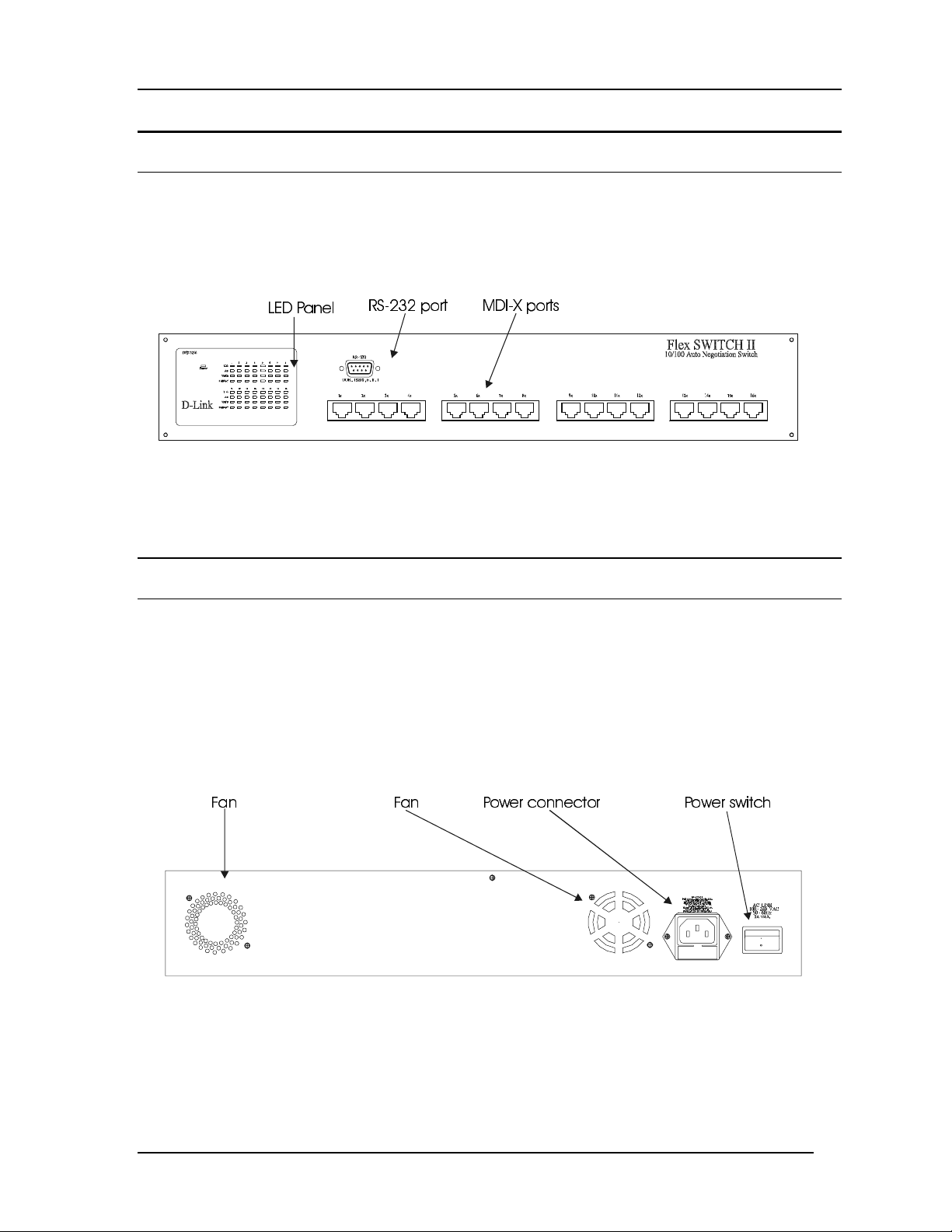
Front Panel
The DES-3216 is designed for management at a glance. The front panel of the DES-3216,
displayed in Figure 1 has LEDs that give you essential information about the DES-3216 at a
glance.
All 16 MDI-X ports on the DES-3216 can be used for network connections.
/('3DQHO
Figure 1: DES-3216 Front Panel
All LEDs are located on the front panel of the DES-3216. Their pur pose is to allo w you to
monitor the operation and performance of the DES-3216 at a glance.
56
SRUW
Rear Panel
The three pronged power plug, two fans and the on/off switch are located at the rear of the
DES-3216 displayed in Figure 2. When installing the DES-3216, leave enough room to allow
you to unplug the power cable if necessary and to attach the RS-232 cable for Local Conso le
Management.
There are heat vents located on the sides. The fans and the vents help to cool the DES-3216.
Always leave two inches of space around the DES - 3216 so that air can circulate and cool the
DES-3216.
)DQ )DQ 3RZHUFRQQHFWRU 3RZHUVZLWFK
Figure 2: Rear Panel
Introduction
3
Page 12

10/100 Auto Negotiation Switch User’s Guide
Management Methods
The DES-3216 supports three management methods:
• Loc al Co ns ole M anagement
• Telnet Management
• D-V iew/ SNMP Management
Local Console Management
Local Console Management is done through the RS-232 Console port. Managing the DES3216 in this mode requires a direct connection between a PC and the DES-3216.
Telnet Management
Telnet is done over the network. Once the DES-3216 is on the network, you can use Telnet to
log in and change the configuration.
D-View/ SN MP Mana gement
The DES-3216 supports SNMP through D-View, D-Link’s proprietary SNMP application
and through other vendors’ SNMP applications. Please refer to the appropriate
documentation for instructions on installing and using D-View and other SNMP applications.
Updating Firmware
Firmware can be updated quickly and easily. See the section Software Update Menu,
Chapter 5, for instructions on updating firmware.
Introduction
4
Page 13

10/100 Auto Negotiation Switch User’s Guide
Installing the DES-3216
This chapter cove rs t he following:
• Unpacking the DES-3216
• Installation options and instructions
• Powering on the DES-3216
Open the box and carefully unpack the DES-3216. You should have all the items on the
follow ing che c klis t:
• DES-3216 10/100 Auto Negotiation Switch
• RS-232 DCE serial cable
• Two mounting brackets and eight screws
• Four rubber pads with adhesive backing
• One six foot (1.82 m) power cord
• DES-3216/3224 User’s Guide CD ROM
2
If any items are missing, co ntact t he reta iler where you purchased the DES-3216 for
assistance.
Be sure to register the DES-3216 immed ia tely. Failure to register the DE S-3216 may void
the warranty.
Installation Options
There are two options for installing the DES-3216: desktop/ shelf installation or rack
installation.
Fo llo w thes e gu idelines for de s kto p/ shelf installation or ra ck installation:
• The surface must support 18 lbs or 8 kg.
• The power source must be within six feet ( 1 . 82 m)
• Power cord and cables should never be stretched
• Leave at least two inches around the DES-3216 for ventilation
The following tools and materials may be necessary to install the DES-3216:
• Screwdriver to install the brackets as needed
• Wire cutters to cut cable as needed for net wor k co nnections
• Crimpers to cr imp cable as needed
• RJ-45 connectors as needed
Desktop/ Shelf Installation
Follow these steps to install the DES-3216 on a desktop or shelf:
1. Place the four rubber pads at the four corners of the DES-3216.
Installing the DES-3216
5
Page 14

10/100 Auto Negotiation Switch User’s Guide
2. Install the DES-3216 on the desktop/shelf where you would like to place it.
Rack Installation
The DES-3216 can be mounted in an EIA standard size, 19 inch rack. The dimensions of the
DES-3216 are 17.4 x 10.4 x 3.2 inches. The DES-3216 can be placed in a wiring closet along
with other equipment.
Follow these steps to install the DES-3216 on a rack:
1. Attach a mounting bracket to each side of the DES-3216 with the screws provided.
2. Slide the DES-3216 into the rack and use the screws provided to secure the DES-3216 to
the rack.
3. Connect the power cord and verify that the DES-3216 is receiving adequate power.
Power On
The power supply will adjust to the local power source automatically. The DES-3216 may be
plugged in without having any or with all LAN segment cables connected.
The power plug is located at the rear of the DES-3216. Plug the cable into the wall socket
and plug the other end into the DES-3216. There is a power on/ off switch located at the rear
of the DES-3216. Move the switch to the on position to power the DES-3216 on. The Power
LED will light and all po rt s w ill auto ne gotiate the prope r speed and dup lex mode when the
DES-3216 is powered on.
Reboot the DES-3216 if there is a problem. Contact D-Link Systems, Inc. for technical
support.
Check the configuration of the DES-3216 after a power failure but do not reset unless it is
necessary.
The DES-3216 can be used with power sources in the range 100 to 240 VAC., 50 to 60 Hz.
Installing the DES-3216
6
Page 15

10/100 Auto Negotiation Switch User’s Guide
Connecting the DES-3216 to the
Network
This chapter cove rs t he following:
• Cable Specifications
• Ports
• Connecting the DES-3216 to another DES-3216
• Connecting the DES-3216 to other switches and hubs
This section deals with making cables and connecting the DES-3216 to other devic es. It is
extremely import ant that cables have the cor r ect pin arrangement and t hat the proper cables
be used when connecting to ser vers, switches, hubs, workstat ions and other devices.
Cable Specifications
3
The type of cable you use depends on the speed of yo ur network. A network running at 10
Mbps can use lower grade cable than a network running at 100 Mbps., Table 1: Cable
Length, indicates cable requirements for Et hernet and Fast Et hernet .
Table 1: Cable Length
Ethernet Type Cable Requirements Maximum Length
10BASE-T Category 3,4, or 5 UTP or STP 328 ft (100 M)
100BASE-TX Category 5 UTP or STP 328 ft (100 M)
Do not use telephone cable. Telephone cable does not support Ethernet or Fast Ethernet.
Use the following guidelines when handling cables:
• Do not st retch or bend cable s .
• Do not put cables near sour ces of electromagnetic inter fere nce.
• Do not create trip hazards by laying cables in aisles and walkways.
• Secure cables to the floor when routing in aisles or walkways.
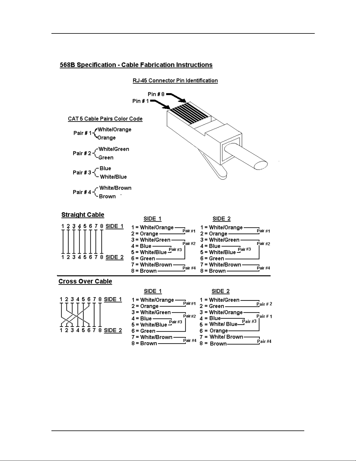
In order for Ethernet or Fast Ethernet to work the wires must be arranged correctly inside the
RJ-45 connector when you make cables. The most common problem on Ethernet o r Fast
Ethernet networks is the cable. If you migrate from Ethernet to Fast Ethernet, make sure the
cables are pinned out properly.
There are two types of cables: str aight through and crossover. Category 3, 4, or 5 UTP/STP
cable has eight wires inside t he sheath. The wires form four pairs. Straight t hro u g h cable ha s
the same pin out, inside the RJ-45 connect or, at both ends. Crosso ver cable has a differe nt
pin arrangement at each end. Fast Ethernet does not tolerate incorr ect pin arrangeme nt s. You
Connecting the DES-3216 to the Network
7
Page 16
10/100 Auto Negotiation Switch User’s Guide
must use the correct pin arrangement in order for the DES-3216 to wo r k properly. See Figure
3 for an example of straight through and crossover cable.
Figure 3: Cable Diagram
Connecting the DES-3216 to the Network
8
Page 17

10/100 Auto Negotiation Switch User’s Guide
Ports
MDI-X Port
MDI-X port s ar e crossover ports. The pin arrangement is the same as the arrange me nt in a
crosso ver cable. The advantage o f an MDI-X port is that you can connect a device with an
MDI-II port without using a crossover cable. The steps for connecting the DES-3216 to 10
Mbps devices or 100 Mbps devices are the same. All the port s will auto negotiate the proper
speed and duplex mode. The DES-3216 has one row of 16 MDI-X ports.
Follow these steps to connect cables to the DES-3216:
1. Check for the appropriate cable configuration for each device.
2. Plug one end of the cable into any of the MDI-X ports.
3. Plug the other end into the appropriate port on the other device.
4. Verify that the LED indicates co nnect ion at the proper speed and dup lex mode.
RS-232 Port
Follow these steps to connect the DES-3216 and another device:
1. Plug one end of the cable provided into the port.
2. Plug the other end into the PC.
3. Run HyperTerminal or a terminal emulation program using the settings given for Local
Console Management at the beginning of Chapter 5, Managing the DES-3216.
DES-3216 to DES-3216 Connection
Connect two DES-3216s together one of the MDI-X ports. The DES-3216 is a lso compatible
with the DES-5016 and DES-5024. Port Trunking can be configured on the device if more
than one port is connected between two DES-3216s or if more than one port is connected
between a DES-3216, DES-3224, DES-5016 and DES-5024. Port trunking increases the
efficiency of the DES-3216 by increasing the bandwidth. See the section on Port Trunking in
Chapter 5 for instructions on how to configure Trunked ports.
Connecting the DES-3216 to the DES-5024 and
Hubs
You can connect the DES-3216 to other switches and hubs on the network. The DES-3216
and the DES-5024 are compatible products that can be connected easily. If you create
multiple connections bet ween devices, cr eate Trunked ports for more efficiency. See the
section on Port Trunking for more details.
Connecting the DES-3216 to the Network
9
Page 18
10/100 Auto Negotiation Switch User’s Guide
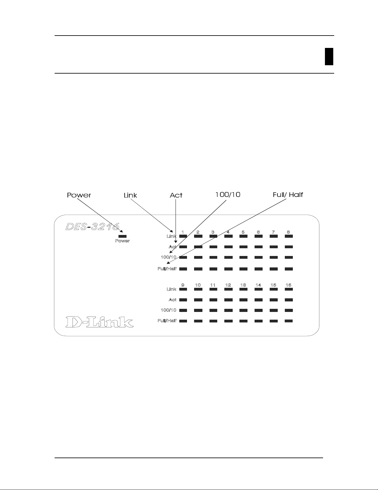
LEDs
The LED panel of the DES-3216, displayed in Figure 4, is designed to allow you to manage
the DES-3216 at a glance. The LEDs indicate the following:
• Power
• Speed
• Link
• Activity
• Duplex mode
All of the LEDs are described in detail. Use the tables to determine the meaning o f each
LED.
4
/LQN $FW
Figure 4: DES-3216 LED Panel
)XOO+DOI
Managing the DES-3216
10
Page 19

10/100 Auto Negotiation Switch User’s Guide
Power LED
The power LED lights when the DES-3216 is powered on. The purpose is to confirm that the
DES-3216 is getting adequate power. See Figure 4.
Table 2: Power LED
Status Color Meaning
On Green DES-3216 is powered on
Off Dark
DES-3216 is powered off , chec k power
cable and connection
DES-3216 LED Panel
The LED panel allows you to manage the DES-3216 at a glance. The first gro up of LEDs is
numbered 1-8 and the second is numbered 9-16. The numbers on the LEDs co r r esponds to
the numbers on the ports. See Table 3: DES-3216 LEDs for an explanation of the LEDs.
The Link LED indicates that there is a link at the port. If a cable is plugged into the port and
the link LED is off, check the cable and connection.
The Act (Activity) LED indicates there is activity, either reception or transmission, at t he
port.
The 100/10 LED indicates the speed of the port. All ports will auto negotiate 100 Mbps or 10
Mbps.
The Full/ Half LED indicates the duplex mode the port is in. Ports in Full are op erat ing at full
duplex. Full duplex means the port is transmit ting and receiving data simultaneously. Ports in
Half a re operating in ha lf duplex. Ha lf d uplex means that dat a is onl y being tr a nsmit ted or
received in one direction at a time.
Managing the DES-3216
11
Page 20

10/100 Auto Negotiation Switch User’s Guide
Table 3: DES-3216 LEDs
LED Green Dark
Link Link is up No link or link is down
Act Flashing, data is passing through the port No data is passing through the port
100/10 Port is working at 100 Mbps Port is working at 10 Mbps
Full/ Half Port is in full duplex m ode Port is in half duplex m ode
Managing the DES-3216
12
Page 21

10/100 Auto Negotiation Switch User’s Guide
Managing the DES-3216
This chapter shows the menus used to manage the DES-3216.
Three types of management are available on the DES-3216:
• Loc al Co ns ole M anage ment ( out- of- band)
• Telnet Mana gement (in- band)
• D-V iew/ SNMP Management
The DES-3216 can be managed in-band or out-of-band. In-band management refers to
managing the DES-3216 through one of the MDI-X ports.
Out-of-band management means going through the RS-232 port.
The interface and options are t he sa me w ith Loca l Console and Telnet Management. The
difference is the type of connection and the port that is used to manage the DES-3216.
D-View is a proprietary SNMP management program. D-View is provided with the DES-
3216. The DES-3216 supports other SNMP management applications and uses standard
MIB. Refer to appropriate documentation for installing and using other SNMP application
programs. The look and feel of D-View is different from other management types. Refer to
ot her docume ntation if yo u are using other vendors’ SNMP applications.
5
All instructions given in this chapter assume that you are logged into the DES-3216 and are
at the appropriate panel for carrying them out.
Local Console Management
Local Console Management is always done through the RS-232 serial port and requires a
direct connection between the DES-3216 and a PC. This type of management is very useful
when the network is down and the DES-3216 cannot be reached by any other means.
Use Local Console Management to log into the DES-3216 for the first time. You do not need
to know the IP address to log into the DES-3216 using Local Console Management. You can
change all the settings and configure the DES-3216, set the IP address and perform other
manag e me nt func tio ns.
Follo w the s e s teps to begin a ma na gement s e s sio n usin g Local Console Manageme nt:
1. Attach the male end of the RS-232 serial cable provided with the DES-3216 to the RS232 port located at the front of the DES-3216.
2. Attach the other end to the serial port of a PC or workstation.
3. Run a terminal emulation program using the following settings:
• Emulation: VT-100/ANSI compatible
• BPS: 19 200
Managing the DES-3216
13
Page 22

10/100 Auto Negotiation Switch User’s Guide
• Data bits: 8
• Parity: None
• Stop bits: 1
• Flow Control: No ne
• Enable: Termin al keys
4. Press Enter to display the login pane l.
5. Log in using the default User Name and Password. The User Name and Password are
case sensitive.
• User Name: D-Link
• Defau lt Pa ssw ord: D-L ink
5. Press Enter to reach the Main menu.
Telnet
You can manage the DES-3216 via Telnet session. However, first you must assign a unique
IP address to the DES-3216. Use Local Conso le Management to log into the DES-3216 for
the first time so that you can assign an IP address. Once you have ass ig ned a n IP addr ess t o
the DES-3216, you can use the management method of your choice.
Telnet management can be done through any of the MDI-X ports on either switch.
Follow these steps to manage the DES-3216 through a Telnet session:
1. Assign an IP address to the DES-3216.
2. Run Telnet.
3. Log into the DES-3216.
Managing the DES-3216
14
Page 23

10/100 Auto Negotiation Switch User’s Guide
Log In
The Log In panel, displayed in Figure 5, is the first panel you see when connecting to the
DES-3216. All management methods require you to log into the DES-3216 with your user
name and password before beginning a management session. For security, you should change
the default User Name and Password.
Figure 5: Log In
Follow these steps to log into the DES-3216 for the first time:
Enter the default User Name and Password and press Enter. The User Name and Password
are case sensitive.
• Default User Name: D-Link
• Defau lt Pa ssw ord: D-Link
The MAC Address at the bottom of the screen cannot be changed.
Managing the DES-3216
15
Page 24

10/100 Auto Negotiation Switch User’s Guide
Help Message
A one page panel, displayed in Figure 6, is available. The menu lists the keystroke and
typographic conventions available on the DES-3216.
Figure 6: Help Message
Managing the DES-3216
16
Page 25

10/100 Auto Negotiation Switch User’s Guide
Panel Conventions
Keystroke Conventions
Example Description
UP, DOWN, or TAB keys Select different items.
SPACEBAR Toggle-switch.
DEL, or BACKSPACE Remove any input character from the screen.
LEFT or RIGHT keys Move cursor backward or for war d.
Ctrl-r Refresh Screen
Typographic Conventions
Example Description
:168.8.254.20 Each read only value follows a colon.
<Enable> Each changeable value can be changed only by the toggle
switch.
[168.8.254.1] Each changeable value is enclosed in square brackets.
EXIT Uppercase letter s indicate a COMMAND item.
Blinking Text Warning Message.
After you are finished viewing the help panel, press Enter to return to the main menu.
Managing the DES-3216
17
Page 26

10/100 Auto Negotiation Switch User’s Guide
Console Program
The Console Program, shown in Figure 7, is the main menu of the DES-3216.
Figure 7: Console Program
System Configuration
The System Configuration menu gives you general information about the DES-3216 and
allows you to assign a LAN IP Address, Subnet Mask, LAN Default Gateway and contact
informat ion o n t he system administra tor.
User Account Management
The User Account Management menu allows you to add users, delete users and modify user
account information.
Switch Port 1-8, 9-16 Configuration
Switch Port 1-8 Configuration and Switch Port 9-16 Configuration allo w you to configure
individual ports. You can set the speed, duplex mode, enable and disable ports and make
other changes.
Spanning Tree Configuration
The Spanning Tree Configuration menu allows you to enable or disable Spanning Tree
Algorithm, se t the B ridge Priority, Hello Time, Forwar d Delay Time and the Max Age Time.
Managing the DES-3216
18
Page 27

10/100 Auto Negotiation Switch User’s Guide
SNMP Management Configuration
The S NMP Manag eme nt Configu ration menu allows yo u to create SN M P Co mmunities and
configure SNMP Trap Manager Settings.
VLAN Port Management
The VLAN Port Management menu allo ws you to create, delete and modify VLANs quickly
and easily.
Trunking Port Manage ment
The Trunking Port Management menu allows you to create, delete and modify Trunking
Ports quickly and easily.
Follow these st eps t o select a menu:
1. Use the tab key or the up and down arrow keys to select an option.
2. Press Ent er.
Managing the DES-3216
19
Page 28

10/100 Auto Negotiation Switch User’s Guide
System Configuration Menu
The System Configuration menu, displayed in Figure 8, allows you to change the
configuration of the DES-3216.
Figure 8: System Configurati on menu
System Information
The System Infor mat ion menu disp lays t he Hardwar e r evisio n, M AC addres s, LAN IP
address and other information on the DES-3216.
System Reset
The System Reset menu allows you to reset the DES-3216 through software rather than
powering off.
Factory Reset to Default Config Values
The Factory Reset to Default Config Values menu a llows you to reload factor y default
configurations.
System Rate Control
The System Rate Control menu allows you to choose Store & Forward or Cut-Through. The
advantages and disadva nt ages of each are explained in a later section.
Managing the DES-3216
20
Page 29

10/100 Auto Negotiation Switch User’s Guide
Software Update
The Software Update menu is used to update the software on the DES-3216. This feature is
only supported through Local Console Management.
Follow these st eps t o select a menu:
1. Highlight the menu option.
2. Press Enter.
System Information Menu
The System Information menu, displaye d in Figure 9, allows you to ent er management and
configuration information on the DES-3216.
Figure 9: System Information menu
Hardware Revision
Specifies the hardware revision and the product generation. Each revision is numbered
incrementally.
Boot PROM Fi rmware Version
Specifies the version of the Boot PROM being used on the DES-3216. Each version is
numbered incrementally.
Managing the DES-3216
21
Page 30

10/100 Auto Negotiation Switch User’s Guide
Software Version
Specifies the software version being used on the DES-3216. You can update the software.
Each version is nu mbered incrementa lly.
MAC Address
Specifies the hardwired address of the DES-3216. This address cannot be changed.
System Description
Brief manufacturer description of the DES-3216. This value cannot be changed.
System Name
Specifies the full name of the DES-3216. This value can be changed, allowing you to assign
a unique name to the DES-3216. You can enter up to 44 char acters.
System Location
Specifies the physical location of the DES-3216, such as a building number or street address.
You can enter up to 44 characters.
System Contact
Specifies the contact infor mat ion of the networ k administr ator . You can enter up to 44
characters.
LAN IP Address
Specifies the unique IP address of your LAN. You can enter up to 15 character s.
LAN Subnet Mask
Specifies the subnet mask, if you are subnetting. If you are not subnett ing leave the default in
place. You can enter up to 15 characters.
LAN Default Gateway
Specifies the default gatewa y. You can enter up to 15 characters.
Follow these steps t o ent er user changea ble information:
Select the field you would like to edit.
1. Delete the default information
2. Ente r the new information.
3. Se lect Save and press Enter. Follow screen prompts.
Managing the DES-3216
22
Page 31

10/100 Auto Negotiation Switch User’s Guide
System Reset
The System Reset panel, displayed in Figure 10, enables you to reset the DES-3216 without
powering off.
Figure 10: System Reset
Some configurations will require you to reset the DES-3216 in order for them to take effect.
Screen prompts will tell you to reset the DES-3216 in order for them to take effect.
Follow these steps to reset the DES-3216:
1. Select Yes.
2. Press Ent er.
To exit without resetting:
1. Select No.
2. Press Ent er.
Managing the DES-3216
23
Page 32

10/100 Auto Negotiation Switch User’s Guide
Factory Reset
The Factory Reset panel, displayed in Figure 11, is used to reset the DES-3216 and restore all
factory default values. Using this panel erase s a ll configurations and customization.
Figure 11: Factor y Reset
Follow these steps to r estor e factor y default configurations:
1. Select Yes
2. Press Ent er.
You will see a confirmation p anel, displaye d in Figure 12. Se le c t Ye s to co nfirm your c hoice .
Select No to return to the System Configuration menu.
Managing the DES-3216
24
Page 33

10/100 Auto Negotiation Switch User’s Guide
Figure 12: Factor y Reset Confirmation
Follow these steps to exit t he panel without r esto r ing factor y default par ameters:
1. Select No or Exit.
2. Press Ent er.
Managing the DES-3216
25
Page 34

10/100 Auto Negotiation Switch User’s Guide
System Rate Control
The System Rate Control panel, displayed in Figure 13, allows you to set the packet
forwarding rate on the DES-3216. There are two options: Store & Forward and Cut-Through.
Figure 13: System Rate Control
The DES-3216 can be set for Store and Forward or Cut-Through. This is a global setting that
affects all the ports except the RS-232 port.
Store and Forward means that when the DES-3216 receives an incoming packet it “stores”
the packet until the entire data packet has been received before it “forwards” the packet to a
destination.
In Cut-Through mode the DES-3216 begins sending out the packet as soon as it receives the
first 128 bytes of data. The first 128 bytes contain the destination of the packet.
Advantages of Store and Forward
Store and Forward only sends out valid data packet s. Bad packets created by collisions on the
network or damaged packets are filtered out .
Always use Store and Forward when some devices on the network run at 10 Mbps and others
run at 100 Mbps.
Disadvan ta ges of Store an d F orwar d
Store and Forward requires more time because it rece ives the who le packet before send ing it
out. Every byte buffered is an additional eight microseconds of delay. For example, 1500
Managing the DES-3216
26
Page 35

10/100 Auto Negotiation Switch User’s Guide
byte packets are delayed by 1200 microseconds in a Store and Forward device versus 60
microseconds in a Cut- T hrough device.
Store and Forward requires more memory because the DES-3216 must store the packet
befo re send ing it out.
Advantages of Cut-Through
Cut-Through is faster because the packet is sent as soon as the first 128 bytes are received.
Cut-Through requires less memory since the DES-3216 only r eads the address but does not
store the entire message.
Disadvantages of Cut-Through
Bad packets are perpetuated, taking up bandwidth.
The benefits diminish in high traffic networks.
Cut-Through can not be used o n networ ks t hat use both Ethernet and Fast Ethernet. The
network must use one or the other.
Follow these steps to change t he default setting from Store and Forward to Cut-Through:
1. Toggle the space bar to change the setting.
2. Select Save and press Enter.
Managing the DES-3216
27
Page 36

10/100 Auto Negotiation Switch User’s Guide
Software Update Menu
The Software Update menu, displayed in Figure 14, is used to upgrade the software on the
DES-3216.
Figure 14: Software Update
Follow these steps to upload new so ftwar e:
1. Load the new software to the hard drive of the PC you will be downloading from. Never
attempt to load softwar e fro m the floppy drive.
2. Connect the DES-3216 and the PC with the software on it with the RS-232 cable
provided. Use the settings given at the beginning of this chapter. Never attempt to load
firmware through Telnet.
3. Select Yes on the Software Updat e menu.
4. You will s e e the pane l displaye d in Figure 15. S e lec t T rans fer on the Hyper Terminal
menu bar a t the top of the s creen.
Managing the DES-3216
28
Page 37

10/100 Auto Negotiation Switch User’s Guide
Figure 15: Software Update Transfer
Figure 16: Send File
5. Select Brow se on the panel displayed in Figure 16. T he brow se opt ion shows the contents
of your hard drive. You must specify the path from the DES-3216 to the file the firmware
is in. Navigate to the file the firmware is sto r ed in and select it. Use XMODE M to
transfer the file.
Managing the DES-3216
29
Page 38

10/100 Auto Negotiation Switch User’s Guide
6. The panel, displayed in Figure 17, will display statistics about the transfer, including the
elapsed time and t he time rema ining .
Figure 17: File Transfer through Xmodem
When the transfer is c omplet e you w ill see the panel in Figure 1 8. T he DES- 3216 will reset
itself automatically and you will have to log in again.
Figure 18: Message Displayed as EEPROM is Being Written
Managing the DES-3216
30
Page 39

10/100 Auto Negotiation Switch User’s Guide
User Account M anagement
The User Account Management panels allow you to add users, delete users and modify user
access rights.
Follow these steps to r each t he User Account Manageme nt panels:
1. Select User Account Management on the Main menu.
2. Press Ent er.
User Account Change Menu
The User Account Change menu, displayed in Figure 19, allows you to add users, delete
users, and modify user r ights.
Figure 19: User Account Change menu
Follow these st eps t o select a menu option:
1. Select an option.
2. Press Ent er.
Create New User
The Create New User panel, displayed in Figure 20, allows you to add new users. Yo u can
have a total of three users on the DES-3216.
Managing the DES-3216
31
Page 40

10/100 Auto Negotiation Switch User’s Guide
Figure 20: Create New User
User Name
Enter the user’s name in this field. User names are case sensitive. Yo u can enter a maximum
of eight character s.
Passwor d
Enter the user’s passwor d in this field. Passwords are case se nsit ive. You can enter a
maximum of eight characters.
Confi rm Password
Reenter the user’s password to confirm it in this field.
Access Level
There are two access levels available on t he DES-3216: Super User and General User.
Super Users have administrative rights on the DES-3216. They can add and delete users,
change the configuration of the DES-3216 and perform all management functions.
General Users have read only access to the DES-3216. They can look at the panels but they
cannot make any changes to existing settings or configurations.
Follow these steps t o add user s:
1. Enter the User Name.
2. Enter the Password.
Managing the DES-3216
32
Page 41

10/100 Auto Negotiation Switch User’s Guide
3. Reenter the password in the Confirm Password field.
4. Toggle the space bar to set the access le vel o f the new user.
5. Select Save and press Enter.
Delete Users
The Delete Users panel, displayed in Figure 21, allows you to delete users from the DES-
3216. As a safety precaution, the DES-3216 will not allow the u s e r who is cu rrently logged
in to delete themselves by accident.
Figure 21: Delete Users
User Name
Identifies the users listed on the DES-3216.
Access Level
Determines whether the user is a Super User with full administrative rights on the network or
a General User with read o nly access rights.
Status
A user’s status can be act ive or inact ive. Only act ive users can log in and make changes.
Inactive users cannot .
Delete
Enables you to delete users.
Managing the DES-3216
33
Page 42

10/100 Auto Negotiation Switch User’s Guide
The following operations can be performed independently of each other or combined.
Follow these steps t o change user Access Level:
1. Select the user’s Access Level.
2. Toggle the space bar to change the current Access Le vel.
3. Select Save and press Enter.
Follow these steps t o change user S tatus Level:
1. Select the user’s St atus Level.
2. Toggle the space bar to select the new St atus Level.
3. Select Save and press Enter.
Follow these st eps t o delete users:
1. Select the Access Level of the user you want to delete.
2. Move the cursor to the Delete column and use the space bar to toggle the option fro m No
to Yes.
3. Press Ent e r .
4. Select Save and press Enter.
Change Password
The Change Password panel, displayed in Figure 22, enables you to change user passwords.
Figure 22: Change Password
Managing the DES-3216
34
Page 43

10/100 Auto Negotiation Switch User’s Guide
User Name
The name of the user whose password you are going to change.
Old Password
The user’s old password.
New Password
The user’s new password.
Confi rm Password
Reenter the new password in this field to confirm it.
Follow these steps t o change user passwords:
1. Enter the user’s name in the User Name field.
2. Enter the user’s old password in the Old Password field.
3. Enter the new password in the New Password field.
4. Reenter the new password in the Confirm Password field.
5. Select Save and press Enter to save your changes.
Managing the DES-3216
35
Page 44

10/100 Auto Negotiation Switch User’s Guide
Switch Port Configuration
The Switch Port Configurat ion panels are used to configure individual ports on the DES-
3216. The only difference between the panels is the port number that t hey deal with. The
options and sett ings are t he sa me for each. Select the group of ports that you want to
configure and then go to the appropriate panel.
Follow these steps t o select a panel:
1. Decide which group of ports you would like to work with.
2. Select the group on the Console Progr am panel.
3. Press Enter to go to the appropriate panel.
Managing the DES-3216
36
Page 45

10/100 Auto Negotiation Switch User’s Guide
Switch Port Configuration Menu
The Switch Port Configuration menu, displayed in Figure 23, enables you to change the
configurations of individual ports.
Figure 23: Switch Port Configuration menu
State
All ports have two states: enabled or disabled. Enabled ports transmit and receive data
packets. Disabled port s can not transmit or receive packet s. Yo u can disable a port but you
will not be able to use a disabled port.
Physical
Refers to the physical state of the port. If you manually change the st ate of a port it will
remain in that state until you change it. It will not auto negotiate speed and duplex mode. All
ports can be in the following physica l stat es:
• Auto
• 100Tx/Half
• 100Tx/Full
• 10Tx/Half
• 10Tx/Full
Ports in the Auto state automat ically negotiat e speed and duplex mode. This is the default
setting.
Ports set in the 100Tx/Half physical state are set to work at 100 Mbps half duplex.
Ports set in the 100Tx/Full state are set to work at 100 Mbps full duplex.
Managing the DES-3216
37
Page 46

10/100 Auto Negotiation Switch User’s Guide
Ports set in the 10Tx/Half state are set to work at 10 Mbps half duplex.
Ports set in the 10Tx/Full state are set to wor k at 1 0 Mbps ful l dup le x.
Port State
All ports have four states: blocking, listening, learning and forwarding. Blocking means that
nothing is coming through the port. If the Spanning Tree Algorithm detects a loop it will
change the state o f the port where the loo p is detected to the Block ing St ate. You can disable
the Spanning Tree Algorithm. Forwarding means the port is forwarding data packets to their
destination. Listening mea ns t hat the po rt is listening for data packets. Learning means the
port is learning the MAC address for data packets. This setting cannot be manually changed.
Priority
The port priority can be set from zero to 255. Zero is the highest port priority. The port
assigned a zero will be the root port. The default set ting will work in most situat ions.
Follow these steps to change t he po rt state:
1. Select the State sett ing of the appro pr iate port.
2. Toggle the space bar to change the current sett ing.
3. Select Save and press Enter.
Follow these steps to change a po rt ’s physical st ate:
1. Select the physical sett ing of the appropriate po rt.
2. Toggle the space bar until you find the appropriate setting.
3. Select Save and press Enter.
Follow these steps t o change t he po rt Priority:
1. Select the Priority of the appropr iate port.
2. Enter a new value between zero and 255.
3. Select Save and press Enter.
Managing the DES-3216
38
Page 47

10/100 Auto Negotiation Switch User’s Guide
Spanning Tree Configuration
The Spanning Tree Configuration panel is used to configur e the Spanning Tree Algorithm.
The Spanning Tree Algorithm (STA) in the DES-3216 allows you to create alternat ive paths
(using multiple switches or bridges) in your network. These backup paths are idle until the
DES-3216 determines that a problem has developed in the primary path. If the primary path
breaks down STA will activate the backup path. STA is very complicated and you should
understand it well before changing the default settings.
STA Operation Levels
STA operates on the bridge level and the port level. On the bridge level, STA calculates t he
Bridge Identifier for each DES- 3216 then sets the Root Br idge and the Designated Br idges.
On the port level, STA sets the Root Port and Designated Ports.
Spanning Tree Configuration Menu
The Spanning Tree Configuration menu, displayed in Figur e 24, a llows you to enable or
disable STA, set bridge priority and other configurations.
Figure 24: Spanning Tree Configuration menu
Spanni n g Tr ee A lg or ithm
Spanning Tree Algorithm can be enabled or disabled. Use Spanning Tree to prevent network
loops.
Managing the DES-3216
39
Page 48

10/100 Auto Negotiation Switch User’s Guide
Bridge Priority
The Bridge Priority can be from 0 to 65535. Zero is the highest Bridge Priority. The higher
the Bridge Priority the greater the chance that the DES-3216 will be sele cte d as the Ro ot
Bridge. The DES-3216 with the highest Bridge Priority is the Root Bridge.
Root Cost
The Root Cost is the number o f times a packet is regenerat ed befor e r eaching its destination.
A source sends a packet to the first device (switch or hub) on the network. When the packet
reaches the next hub or sw itch and is sent out again, the Path Cost becomes two. Each switc h
and active hub regenerates the packet . To determine the Root P ath Co st, count the number of
times the packet is regenerated.
The switch with the lowest Path Cost is the Root Bridge. Make the Root Bridge the best
switch on the network.
Hello Time
Is the interval between two transmiss io ns o f packets sent by the Root Bridge to tell all other
switches that it is the Root Br idge. The Hello T ime can be set manuall y, wit h a range in
seconds fro m 1 to 10. If the Hello Time is set for the sw itch and the sw itch is not the Root
Bridge then the Hello Time will not take effect until the switch becomes the Root Bridge.
Forward Delay Time
This is the time any port on the DES-3216 spends in the listening state while moving from
the listening stat e to the forwarding state. It can be set from 4 to 30 seconds.
Use the following formula when setting the Hello Time and the Forward Delay Time:
2 x (Forward Delay minus 1 second) > Max Age
2 x (H ello Time plus 1 second) < Max Age
Max Age Time
Is the time a non-root bridge waits for a packet to be sent. At t he end of the Max Age, if a
packet has not been received from the Root Bridge, the DES-3216 will start sending its own
packets and request permission to become the Root Bridge. If it turns out that the DES-3216
has the lowest Br idge Ident ifier it w ill become the Root Bridge.
The switch with the lowest Bridge Identifier is the Root Bridge. It is best to make the Root
Bridge the best switch on the network to ensure the best network performance and reliability.
Root Bridge
Specifies the MAC address of the Root Bridge. The DES-3216 may or may not be the root
bridge. The DES-3216 is the default root bridge.
Managing the DES-3216
40
Page 49

10/100 Auto Negotiation Switch User’s Guide
Root Port
Specifies the preferred path to the Root Bridge. Only one path per bridge can exist. The
de fau lt set ting is none.
Table 4: User Selective STA parameters
STA parameters Settings Effects Comment
Enable/Di sabl e Enable/
Disable
Bridge Priority Lower the
#, higher
the
priority
Hello Time 1 – 10
seconds
Max Age Time 6 – 40
seconds
Forward Delay 4 – 30
seconds
Port Level STA parameters
Enable/ Disable Enable/
disable
Port Priorit y Lower the
#, higher
the
priority
Participate in or
remove from
STA
Increases
chance of
becoming the
Root Bridge
No effect, if not
Root Bridge
Compete for
Root Bridge, if
BPDU is not
received
High # delays
the change in
state
Enable or
disable LAN
segment
Increases
chance of
becoming the
Root Port
Enable in a
SNMP network.
Avoid, if the
switch is used in
workgroup level of
a large network
Never set greater
than Max Age
Time
Avoid low number
for unnecessary
reset of Root
Bridge
Max Age < 2 x
(Forward Delay -
1)
Max Age > 2 x
Hello Time + 1)
Disable a port for
security or
problem isolation
Managing the DES-3216
41
Page 50

10/100 Auto Negotiation Switch User’s Guide
SNMP Management Configuration
The SNMP Management Configuration panel is used to configure the DES-3216 for SNMP
management. Leave the default values in place if you are not managing your network
through SNMP.
The DES-3216 uses the standard MIB-II Manageme nt Infor mation Base module. The MI B
values can be retrieved from any SNMP based network manager. The DES-3216 supports its
own proprietar y enterprise as an extended MIB. The MIB can be ret r ieved by specif ying t heir
Object-Identity (OID). MIB values can be either read-only or read-write.
Read-only MIB variables can be constants that are programmed into the DES-3216 or
variables that change while the DES-3216 is running. For example, the number and type of
ports on the DES-3216 is a read-only constant. The number and type of ports is fixed.
Statistics, such as the number of errors that have occurr ed, are read- only variables.
Read-write MIBs ar e usually related to user custo mized configurations. Examples of these
are the DES-3216’s IP address, STA parameters and port status.
If you use third party vendors’ SNMP software to manage the DES-3216, a diskette listing
the DES-3216’s proprietary enterprise MIB can be obtained by request. If your software
provided functions to browse or modify MIB, you can get the MIB values and change them
(if the MIB’s att r ibutes permit the write opt ion). This process can be difficult. You must
know the MIB OIDs and retrieve them one by one.
SNMP Management Configuration Menu
The SNMP Management Configuration menu, displayed in Figure 25, enables you to
configure the DES-3216 for SNMP management.
Managing the DES-3216
42
Page 51

10/100 Auto Negotiation Switch User’s Guide
Figure 25: SNMP Management Configurat i on menu
SNMP Manager Setting
The fields under this setting are used to configur e the DES-3216 for SNMP Management.
You must configure these fields in order to manage the DES-3216 through SNMP.
SNMP Community String
The SNMP Community String field allows you to name the SNMP Communities. The names
public and private are only default names. For security you should change these names to
help prevent unauthorized access to the DES-3216.
You can name the SNMP communities anything you like. Yo u can enter up to 32 characters
in each of the four fields. You can create up to four SNMP Communities.
Access Right
Enables you to set t he rights that members of the SNMP Communit ie s have. Read Only
access rights mean t hat members o f the community ca n view the information on the DES3216 but they can not make changes to the configurations. Read/ Write access rights allow
the members of the community to make any changes they desire.
Status
Can be Valid or Invalid. Only communities with Valid status can access the DES-3216.
Communities with Invalid status cannot access t he DES-3216.
Managing the DES-3216
43
Page 52

10/100 Auto Negotiation Switch User’s Guide
SNMP Trap Manager Setting
Enables you to enter the IP addresses of Trap Managers. Traps are messages the DES-3216
sends out to inform trap managers of events on the network. The DES-3216 generates traps
and sends them to the netwo rk manager. Tr ap managers ar e special network users who ar e
given certain rights and access to oversee and mainta in the net wor k. This featur e is available
only in D-View or by using other SNMP management software.
You can specify which network managers may receive traps from the DES-3216 by creating
a list of IP Addresses of the authorized network managers.
Trap managers can receive the following t rap types:
• Cold Start
• Authenticat ion Failure
• Link Change Event
Cold Start
Signifies that the DES-3216 has been powered up. Software settings are reconfigured and
hardware syste ms are rebooted. A cold start is d ifferent from a factory reset.
Authenti ca tion Fail ur e
Signifies that an addressee (or manager/ user) on the DES-3216 is not a valid user of the
DES-3216 and may have entered an incorrect community name.
Link Change Event
Signifies that the link of a port has changed from link up to link down or vic e versa.
IP Address
This field is used to enter the IP Addresses of Trap Managers.
SNMP Community String
Enter the Co mmunity St ring of the Trap Mangers in this field.
Status
The DES-3216 will not send out traps unless the status is Valid.
Follow these steps t o ent er t he SNMP Co mmunit y String:
1. Enter the name of the SNMP Community.
2. Select the Access Right field and toggle the space bar to select Read Only or Read/
Write.
3. Select the Status field and toggle the space bar to se lect Valid or I nvalid.
4. Select Save and press Enter.
Managing the DES-3216
44
Page 53

10/100 Auto Negotiation Switch User’s Guide
Follow these steps to configure t he SNMP T r ap Manager Setting:
1. Enter the IP Address of the Trap Manager.
2. Enter the name of the SNMP Community String.
3. Select Stat us and to ggle the space bar to se lect Va lid or Invalid.
4. Select Save and press Enter.
Managing the DES-3216
45
Page 54

10/100 Auto Negotiation Switch User’s Guide
VLAN Port Management
A Virtual Local Area Network (VLAN) is a logical subgroup within a LAN that is created
with software rather than physical connections. The purpose of a VLAN is to prevent
broadcast storms and ease congestion on your network.
Each VLAN created is a broadcast domain. A broadcast is a packet that is sent to all nodes
on t he netw or k. A broadcast doma in is a domain in w hich every node in the d omain receives
the broadcast packet. T he advantage of creating VLANs is that they permit you to group
LAN segments together in order to get the most out of yo ur network.
VLANs become more important as the network grows and traffic increases. VL ANs are
usually used on high traffic networks. You should consider a VLAN on a smaller network if
a department or workgroup routinely does tasks that take up a lot of bandwidth and they are
not already o n their o wn LAN s egment .
VLANs can be used to subdivide the network. The DES-3216 supports port based VLAN.
Port based VLAN means that the VLAN is grouped by port. If a VLAN is created using three
ports, then those ports become a separat e bro adcast do main.
By using VLANs, members of a particular department or workgroup can be partitioned from
the rest of the network. For example, the marketing department can be on one VLAN and the
accounting depart ment can be on anot her. I f a workst at ion in market ing sends a broadcast
packet to another workstation in market ing the packet will remain in the marketing VLAN.
VLAN Port Management Menu
The VLAN Port Management menu, displayed in Figur e 26, enables you to create, delete and
modify VLANs on the DES-3216.
Managing the DES-3216
46
Page 55

10/100 Auto Negotiation Switch User’s Guide
Figure 26: VLAN Port Management menu
Follow these steps to cr eate, delete and modify VLAN:
1. Select the appropriate option.
2. Press Ent er.
Managing the DES-3216
47
Page 56

10/100 Auto Negotiation Switch User’s Guide
Create New VLAN
The Create New VLAN menu, displayed in Figure 27, is used to create a new VLAN. The
default value is that all ports belong to one VLAN. You can create up to eight separate
VLANs. Ports can belong to two VLANs at the same t ime. Each VLAN is a broadcast
domain. If you have created a trunking group, you must include the entire trunk group in the
VLAN.
Figure 27: Create New VLAN menu
New VLAN Name
Is the name of the VLAN you are creating. All VLANs must have a unique name.
Port #
Is the number of the port. The numbers on the panel match the ports on the DES-3216. Some
ports are combined. For example, ports 1 and 3 are shown as “Port 1/3”. Ports t hat are
grouped together must be part of the same VLAN.
TrunkGroup
This field identifies the trunk group that the port has been assigned to. The field is open if the
port has not been assigned to a Trunk Group.
Status
The status field can be either avai lable o r selected. Available indicates that t he port is
available for inclusion in a VLAN. Selected indicates the port has been assigned to a VLAN.
Managing the DES-3216
48
Page 57

10/100 Auto Negotiation Switch User’s Guide
All ports will have a status of available on th is panel, eve n after the y have been selected as
part of a VLAN. There is nothing on this panel that indicates the port is already part of a
VLAN.
Follow these steps t o cr eat e a VLAN:
1. Enter the name of the VLAN you are creating.
2. Select the ports you want to include in the VLAN and toggle the space bar to change the
status fro m Available to Selected.
3. Select Save and press Enter.
Delete VLAN M enu
The Delete VLAN menu, displayed in Figure 28, is us ed to delete VLANs.
Figure 28: Delete VLAN menu
VLAN Name
Is the name of the VLAN.
Delete
After you have created a VLAN, this column will have the option to delete it.
Follow these steps t o delet e VLANs:
1. Select the VLAN you want to delete in the Delete column.
2. Toggle the space bar to Yes to delete the VLAN.
3. Select Save and press Enter.
Managing the DES-3216
49
Page 58

10/100 Auto Negotiation Switch User’s Guide
4. A screen p rompt will warn yo u tha t you must reset the DES-3216 in order for the change
to take effect.
Modify VLAN Menu
The Modify VLAN menu, displayed in Figure 29, enables you to modify VLANs.
Figure 29: Virtual LAN Name
Virtual LAN Name
The names of all VLANs appear in this column.
Follow t hese st eps t o modify VLANs:
1. Select the name of the appropriate VLAN.
2. Press Ent er.
3. You will see t he VLAN Modify menu. Use this p a nel t o modify a V LAN.
4. Select the ports that you want to include in the VLAN or delete from the VLAN. Toggle
the space bar to change the current sett ing. Available means t he port is available for
inclusion in the VLAN. Selected mea ns t he po rt has been select ed as par t of a VLAN.
5. Select Save and press Enter to implement your changes.
Managing the DES-3216
50
Page 59

10/100 Auto Negotiation Switch User’s Guide
Trunking Port Management Menu
The Trunking Port Management panels are used to create, delete and modify trunk ports.
Figure 30: Trunking Port Management menu
Follow these steps to cr eate, delete and modify trunk ports:
1. Select the appropriate option.
2. Press Ent er.
Managing the DES-3216
51
Page 60

10/100 Auto Negotiation Switch User’s Guide
Create New Trunking Port
The Create New Trunking Port panel, displayed in Figure 31, is used to create Trunk Ports.
You can create up to seven trunking groups with up to eight ports in each group. Each
Trunking Group acts like a single port.
Figure 31: Create New Trunki ng Port
New Trunking Group Name
Is the name of the Tunking Group you are going to create. All Trunking Groups must have a
name.
Port #
Is the number of the port. The numbers on the panel match the ports on the DES-3216. Some
ports are not available for trunking. For example, port 3 has a status of N/A. Ports t hat are
shown as N/A are not available for inclusion in any trunking groups.
Name
This field identifies the TrunkGroup that the port has been assigned to. The field is open if
the port has not been assigned to a TrunkGroup.
Status
The status field can be either avai lable o r selected. Available indicates that t he port is
available for inclusion in a TrunkGroup. Selected indicates the port has been assigned to a
TrunkGroup. All ports will have a status of available on this panel, even after they have been
Managing the DES-3216
52
Page 61

10/100 Auto Negotiation Switch User’s Guide
selected as part of a TrunkGroup. There is nothing on this panel that indicates t he po rt is
already part of a TrunkGroup.
Follow these steps to cr eate a Tr unkGroup:
1. Enter the name of the TrunkGroup.
2. Select the ports you want to include in the TrunkGroup and toggle the space bar to
change the status fro m Available to Selected.
3. Select Save and press Enter.
Delete Trunking Port
The Delete Trunking Port panel, displayed in Figure 32, is used to delete Trunk Ports.
Figure 3 2: Delete Tr unking Por t
Trunking Port
Is t he name of the T runking Group.
Delete
After you have created a Trunking Group, this column will have the option to delete it.
Follow these steps to delet e a Trunk ing Gro up:
1. Select the Trunking Group you want to delete in the Delete column.
2. Toggle the space bar to Yes to delete the Trunking Group.
3. Select Save and press Enter.
Managing the DES-3216
53
Page 62

10/100 Auto Negotiation Switch User’s Guide
Modif y Tru nking Port
The Modify Trunking Port panel, displayed in Figure 33, enables you to Modify Trunking
Ports.
Figure 33: Modify Trunking Port
Trunking Port Name
The names of all Trunked Ports appear in this column.
Follow these steps to modify Trunked Ports:
1. Select t he name of the appropriate Trunked Port.
2. Press Ent e r .
3. You will se e the M odif y T runking P ort panel sho w n in Figure 33. U s e this panel to
modify a Trunking Group.
4. Select the ports that you want to include in the Trunking Group or delete from the
Trunking Group. Toggle the space bar to change the current sett ing. Available means the
port is available for inclusion in the Trunking Group. Selected means the port has been
selected as part of a Trunking Group. N/A indicates ports that are not available for
inclusion in any trunking group.
5. Select Save and press Enter to implement your changes.
Managing the DES-3216
54
Page 63

10/100 Auto Negotiation Switch User’s Guide
6
Troubleshooting
This troubleshooting sec tion is inte nd ed to he lp you solve the most commo n problems on the
DES-3216.
The DES-3216 does not have external LED error messages. If there is an error and it cannot
be resolved by implementing the solutions in this section, contact D-Link Technical Support.
All LEDs are explained in detail in Chapter 4, LEDs. If you are having a problem that is not
discussed here, contact technical support.
Problem Solution
POST Errors The DES-3216 performs a Power On Self Test (POST) every time it is
powered on. If you are connected to the DES-3216 through Local
Console Management dur ing the POST you can see the results
displayed on your monitor. The login screen appears after the DES3216 has completed the POST.
The POST checks all of the hardware components on the DES-3216.
Cables Faulty cables are the most common source o f pro blems on Ethernet
and Fast Ethernet networks. Check t he cables first if you are having
any problems connecting to a device.
Ethernet is more fault tolerant than Fast Ethernet. If you are moving
from Ethernet to Fast Ethernet, make sure the cables are p inned out
correctly. See Chapter 3, Connecting the DES-3216 to the Network,
Cable Specifications, for a diagram showing the proper pin
arrangement fo r Ethernet and Fast Ethernet.
Port States All ports on the DES-3216 have two modes: auto negotiation mode
and forced mode. Ports in auto negotiation mode auto negotiate the
proper speed and duplex mode. Ports in forced mode have been
manually set to a particular speed and duplex mode. Check the LEDs
on the DES-3216 and on the Network Interface Card to verify settings.
See Chapter 4, LEDs, for an explanat ion of all LEDs.
The port settings on the DES-3216 and the port settings on the device
you are connecting to must be t he sa me in order for t hem to
communicate. Check the speed and duplex setting on both the port and
device you are connecting to.
Power LED is Off Check the power plug and verify that you are getting power from the
wall socket. If the DES-3216 is on, the power LED is not working
properly. Return the DES-3216. If the DES-3216 is not powering on
Troubleshooting
55
Page 64

10/100 Auto Negotiation Switch Users’ Guide
and power is being received though the wall socket, the power supply
is not working. Return the unit.
All LEDs are Off Check the power plug and verify that the DES-3216 is receiving
adequate power. Log in to the DES-3216 using Local Console
Management, see Chapt e r 5 , Managing the DES-3216, for instructions.
Power the DES-3216 off and then power it on again. Use the monitor
to check the error messages. Return the DES-3216 to D-Link for
service if the p ro b lem per sists.
Forget Password I f you forget your password, contact D-Link Technical Support at
(949) 788-0805 for assistance or check our web site at
www.dlink.com.
Troubleshooting
56
Page 65

10/100 Auto Negotiation Switch User’s Guide
Appendix A
DES-3216 Technical Specifications
Switch Specifications
• Complies with IEEE 802.3 CSMA/CD 10 Base-T, 100 Base-TX
• Complies with IEEE 802.1d Spanning T ree
• Switched IEEE 802.3 MAC layer frame size: 64-1518
• NWAY Auto-negotiation for each 10 Base-T/ 100 Base-TX network port providing
auto-detection of connected cable type, auto-sensing of full and half duplex signaling
and auto-configuration
• Cut-Through and Store-and-For war d sw itching for re liable error - free packet t ransfers
• Native SNMP management support with Ethernet MIB II (RFC 1213), RMON MIB
(RFC 1757) and bridge MIB (RFC 1493)
• 8,192 maximum entries for MAC address Table
• Comprehen sive LED ind icators display of the system/ port status
• 512KB EEPROM (flash memory) for firmware upgrade
• RS-232 (DB-9) port for Out-of-Band management (asynchronous, 8-bit data, 1 stop
bit, no parity, 19.2 K baud)
• Rack mountable (Fits standard 1.5 U EIA 19” rack)
• Includes 16 10/100 Mbps Ethernet ports with built-in support of RMON and VLAN
• Supports Trunking Group
Port Specifications
• 16 RJ-45 ports for Cat 3, 4, or 5 UTP cable (Cat. 5 req. for 100 Base-TX)
• 10 or 100 Mbps data transfer rate
• NWAY Auto - ne go tiatio n
• Full or Half Duplex
Appendix A
57
Page 66

10/100 Auto Negotiation Switch Users’ Guide
General
Standards:
Protocol:
Data Transfer Rate: Fast Ethernet:
Topology:
Network Cables: 10 Base-T:
Number of Ports:
IEEE 802.3 10 Base-T Ethernet
IEEE 802.3u 100 Base-TX Fast Ethernet
ANSI/IEEE Std 802.3 NW AY™ Auto
Negotiation
IEEE 802.3 Frames types: Transparent
IEEE 802.3 MAC layer frame size: 64-1518
CSMA/CD, Full Duplex
100 Mbps (half duplex )
200 Mbps (full duplex )
Star
2-pair UTP Cat. 3 (100 m)
4-pair UTP Cat. 4, 5 (100 m)
EIA/ TIA-568 150-ohm STP ( 100 m)
100 Base-TX:
4-pair UTP Cat. 5 (100 m)
EIA/ TIA-568 150-ohm STP ( 100 m)
16 x 10/100 Mbps NWAY Ethernet port s
Appendix A
58
Page 67

10/100 Auto Negotiation Switch User’s Guide
Physical and Environmental
AC inputs: 100 – 240 VAC, 50/60 Hz (internal univ er sal power
supply)
Power
Consumption:
DC fans: 2 built in 60 x 60 mm fans
70 watts maximum
Operating
Temperature:
Storage
Temperature:
Humidity: 5% ~ 95% non-c ondensi ng
Dimensions: 441 x 264 x 81 mm (1.5 U), 19 inch rack-mount
Weight: 4.3 Kg
EMI: FCC Class A, CE Mark Class A, VCCI Class A
Safety: UL (UL 1950), CSA (CSA 950) , TUV/GS EN60950)
0 ~ 50 degrees Celsius
-25 ~ 70 degrees Celsius
width
Appendix A
59
Page 68

10/100 Auto Negotiation Switch Users’ Guide
Performance
Transmission
Method:
RAM Buffer: 1 M bytes per dev ice
Cut-Through and St or e- and- Forward
Filtering A ddr ess
Table:
Packet Filtering/
Forwarding Rate:
MAC Address
Learning:
8 K entries per device
148810 pps per port (for 100 Mbps)
Automatic updat e
Max age: five minutes
Appendix A
60
Page 69

Index
A
Access Level................................................32, 33
Access Right..................................................... 43
All LEDs Off.................................................... 56
Audience.............................................................1
Authentication...................................................44
B
Boot PROM Firmware ...................................... 21
Bridge Priority .................................................. 40
C
Cable Specifications............................................ 7
Cables............................................................... 55
Change Password .............................................. 34
Cold Start.......................................................... 44
Conf ir m p assword............................................. 32
Confirm Password........................................32, 35
Console Program............................................... 18
Create New Trun king Port................................. 52
Create New Us er ............................................... 31
Create VLAN.................................................... 48
Cut Th rough...................................................... 27
Cut-T h rough ..................................................... 26
D
Delete ....................................................33, 49, 53
Delete Trun king Por t......................................... 53
Delete Users...................................................... 33
Delete VLAN.................................................... 49
DES-3216 LEDs............................................... 11
DES-3216 to DES-3216 connection..................... 9
F
Factory Reset...............................................20, 24
Featur es ..............................................................2
Forget Passwor d................................................ 56
Forwar d Delay Time ......................................... 40
Front Panel..........................................................3
IP Address ........................................................ 44
L
LAN Default Gateway....................................... 22
LAN IP Address................................................ 22
LAN Subnet Mask............................................ 22
Link Change ..................................................... 44
Local Console Management .......................... 4, 13
Log In............................................................... 15
M
MAC Address ................................................... 22
Management Meth ods......................................... 4
Max Age Time.................................................. 40
MDI-X Port ........................................................ 9
Modify Trunking Port ....................................... 54
Modify VLAN Menu.........................................50
N
New Password................................................... 35
New Trunking Gr oup ........................................ 52
New VLAN Name.............................................48
O
Old Password.................................................... 35
Organization ....................................................... 1
P
Panel Conventions............................................. 17
Password........................................................... 32
Physical............................................................ 37
Port................................................................... 48
Port #................................................................ 52
Port State.......................................................... 38
Port States......................................................... 55
Ports...................................................................9
POST Errors ..................................................... 55
Power ................................................................. 6
Power LED..................................................11, 55
Priority..............................................................38
G
General User..................................................... 32
H
Hardware Revision............................................ 21
Hello Time ........................................................ 40
Help Message....................................................16
I
Install DES-3216.................................................5
Instal lation...................................................... 5, 6
R
Rear Panel...........................................................3
Root Bridge.......................................................40
Root Cost.......................................................... 40
Root Port........................................................... 41
S
SNMP Community.......................................43, 44
SNMP Management .................................4, 19, 42
SNMP Setting ................................................... 43
SNMP Trap ....................................................... 44
61
Page 70

Software Update...........................................21, 28
Software Version .............................................. 22
Span ni n g Tree................................................... 18
Span ni n g Tree Alg. ........................................... 39
Span ni n g Tree Config ....................................... 39
Span ni n g Tree Config. ...................................... 39
STA Operation.................................................. 39
State..................................................................37
Status......................................... 33, 43, 44, 48, 52
Store and Forward............................................. 26
Super User ........................................................ 32
Switch Port Con figuration............................36, 37
System Configuration........................................ 18
System Configuration Menu.............................. 20
System Contact................................................. 22
System Description........................................... 22
System Information........................................... 20
System Information Menu................................. 21
System Location................................................ 22
System Name.................................................... 22
System Rate Con trol.....................................20, 26
System Reset................................................20, 23
T
Telne t........................................................... 4, 14
TrunkGroup.................................................48, 52
Trunking Port.................................................... 53
Trunking Port Management..........................19, 51
Trunking Port Name.......................................... 54
U
Unpacking .......................................................... 5
User Account Change........................................31
User Account Management ..........................18, 31
User Name.............................................32, 33, 35
V
Virtual LAN Name ............................................ 50
VLAN............................................................... 46
VLAN Name.....................................................49
VLAN Port ....................................................... 46
VLAN Port Management ................................... 19
62
 Loading...