


AV SURROUND RECEIVER
AVR-4311CI
Owner’s Manual
Simple version
v 4
Basic version
v 14
Advanced version
v 53
Information
v 119
“Part names and functions” (vpage 120)
nSAFETY PRECAUTIONS
CAUTION
RISK OF ELECTRIC SHOCK
DO NOT OPEN
CAUTION:
TO REDUCE THE RISK OF ELECTRIC SHOCK, DO NOT REMOVE COVER (OR BACK). NO USER-SERVICEABLE PARTS INSIDE. REFER SERVICING TO QUALIFIED SERVICE PERSONNEL.
The lightning flash with arrowhead symbol, within an equilateral triangle, is intended to alert the user to the presence of uninsulated “dangerous voltage” within the product’s enclosure that may be of sufficient magnitude to constitute a risk of electric shock to persons.
The exclamation point within an equilateral triangle is intended to alert the user to the presence of important operating and maintenance (servicing) instructions in the literature
accompanying the appliance.
WARNING:
TO REDUCE THE RISK OF FIRE OR ELECTRIC SHOCK, DO NOT EXPOSE THIS APPLIANCE TO RAIN OR MOISTURE.
CAUTION:
HOT SURFACE. DO NOT TOUCH.
The top surface over the internal heat sink may become hot when operating this product continuously.
Hot Do not touch hot areas, especially around the “Hot surface surface mark” and the top panel.
mark PRECAUTION:
SURFACE CHAUDE. NE PAS TOUCHER.
La surface supérieure du dissipateur de chaleur peut devenir chaude si vous utilisez ce produit en continu.
Ne touchez pas les zones chaudes, tout particulièrement vers l’inscription “Hot surface mark” et le panneau supérieur.
IMPORTANT SAFETY
INSTRUCTIONS
1.Read these instructions.
2.Keep these instructions.
3.Heed all warnings.
4.Follow all instructions.
5.Do not use this apparatus near water.
6.Clean only with dry cloth.
7.Do not block any ventilation openings.
Install in accordance with the manufacturer’s instructions.
8.Do not install near any heat sources such as radiators, heat registers, stoves, or other apparatus (including amplifiers) that produce heat.
9.Do not defeat the safety purpose of the polarized or grounding-type plug. A polarized plug has two blades with one wider than the other. A grounding type plug has two blades and a third grounding prong. The wide blade or the third prong are provided for your safety. If the provided plug does not fit into your outlet, consult an electrician for replacement of the obsolete outlet.
10.Protect the power cord from being walked on or pinched particularly at plugs, convenience receptacles, and the point where they exit from the apparatus.
11.Only use attachments/accessories specified by the manufacturer.
12.Use only with the cart, stand, tripod, bracket, or table
specified by the manufacturer, or sold with the apparatus. When a cart is used, use caution when moving the cart/ apparatus combination to avoid injury from tip-over.
13. Unplug this apparatus during lightning storms or when unused for long periods of time.
14.Refer all servicing to qualified service personnel.
Servicing is required when the apparatus has been damaged in any way, such as power-supply cord or plug is damaged, liquid has been spilled or objects have fallen into the apparatus, the apparatus has been exposed to rain or moisture, does not operate normally, or has been dropped.
15.Batteries shall not be exposed to excessive heat such as sunshine, fire or the like.
CAUTION:
To completely disconnect this product from the mains, disconnect the plug from the wall socket outlet.
The mains plug is used to completely interrupt the power supply to the unit and must be within easy access by the user.
PRECAUTION:
Pour déconnecter complètement ce produit du courant secteur, débranchez la prise de la prise murale.
La prise secteur est utilisée pour couper complètement l’alimentation de l’appareil et l’utilisateur doit pouvoir y accéder facilement.
FCC INFORMATION (For US customers)
1.COMPLIANCE INFORMATION
Product Name: AV Surround Receiver Model Number: AVR-4311CI
This product complies with Part 15 of the FCC Rules. Operation is subject to the following two conditions: (1) this product may not cause harmful interference, and (2) this product must accept any interference received, including interference that may cause undesired operation.
Denon Electronics (USA), LLC (a D & M Holdings Company) 100 Corporate Drive Mahwah, NJ 07430-2041 Tel. (800) 497-8921
2.IMPORTANT NOTICE: DO NOT MODIFY THIS PRODUCT
This product, when installed as indicated in the instructions contained in this manual, meets FCC requirements. Modification not expressly approved by DENON may void your authority, granted by the FCC, to use the product.
3.IMPORTANT
When connecting this product to network hub or router, use only shielded STP or ScTP LAN cables which is available at retailer.
Follow all installation instructions. Failure to follow instructions could void your authority, granted by the FCC, to use the product.
4.NOTE
This product has been tested and found to comply with the limits for a Class B digital device, pursuant to Part 15 of the FCC Rules. These limits are designed to provide reasonable protection against harmful interference in a residential installation.
This product generates, uses and can radiate radio frequency energy and, if not installed and used in accordance with the instructions, may cause harmful interference to radio communications. However, there is no guarantee that interference will not occur in a particular installation. If this product does cause harmful interference to radio or television reception, which can be determined by turning the product OFF and ON, the user is encouraged to try to correct the interference by one or more of the following measures:
•Reorient or relocate the receiving antenna.
•Increase the separation between the equipment and receiver.
•Connect the product into an outlet on a circuit different from that to which the receiver is connected.
•Consult the local retailer authorized to distribute this type of product or an experienced radio/TV technician for help.
For Canadian customers:
This Class B digital apparatus complies with Canadian ICES-003.
Cet appareil numérique de la classe B est conforme à la norme NMB-003 du Canada.
I
nNOTES ON USE / OBSERVATIONS RELATIVES A L’UTILISATION
WARNINGS |
AVERTISSEMENTS |
|
|
• Avoid high temperatures. |
• Eviter des températures élevées. |
Allow for sufficient heat dispersion when installed in a rack. |
Tenir compte d’une dispersion de chaleur suffisante lors de l’installation sur |
• Handle the power cord carefully. |
une étagère. |
Hold the plug when unplugging the cord. |
• Manipuler le cordon d’alimentation avec précaution. |
• Keep the unit free from moisture, water, and dust. |
Tenir la prise lors du débranchement du cordon. |
• Unplug the power cord when not using the unit for long periods of time. |
• Protéger l’appareil contre l’humidité, l’eau et la poussière. |
• Do not obstruct the ventilation holes. |
• Débrancher le cordon d’alimentation lorsque l’appareil n’est pas utilisé |
• Do not let foreign objects into the unit. |
pendant de longues périodes. |
• Do not let insecticides, benzene, and thinner come in contact with the unit. |
• Ne pas obstruer les trous d’aération. |
• Never disassemble or modify the unit in any way. |
• Ne pas laisser des objets étrangers dans l’appareil. |
• Ventilation should not be impeded by covering the ventilation openings with |
• Ne pas mettre en contact des insecticides, du benzène et un diluant avec |
items, such as newspapers, tablecloths or curtains. |
l’appareil. |
• Naked flame sources such as lighted candles should not be placed on the |
• Ne jamais démonter ou modifier l’appareil d’une manière ou d’une autre. |
unit. |
• Ne pas recouvrir les orifices de ventilation avec des objets tels que des |
• Observe and follow local regulations regarding battery disposal. |
journaux, nappes ou rideaux. Cela entraverait la ventilation. |
• Do not expose the unit to dripping or splashing fluids. |
• Ne jamais placer de flamme nue sur l’appareil, notamment des bougies |
• Do not place objects filled with liquids, such as vases, on the unit. |
allumées. |
• Do not handle the mains cord with wet hands. |
• Veillez à respecter les lois en vigueur lorsque vous jetez les piles usagées. |
• When the switch is in the OFF position, the equipment is not completely |
• L’appareil ne doit pas être exposé à l’eau ou à l’humidité. |
switched off from MAINS. |
• Ne pas poser d’objet contenant du liquide, par exemple un vase, sur |
• The equipment shall be installed near the power supply so that the power |
l’appareil. |
supply is easily accessible. |
• Ne pas manipuler le cordon d’alimentation avec les mains mouillées. |
|
• Lorsque l’interrupteur est sur la position OFF, l’appareil n’est pas |
|
complètement déconnecté du SECTEUR (MAINS). |
|
• L’appareil sera installé près de la source d’alimentation, de sorte que cette |
|
dernière soit facilement accessible. |
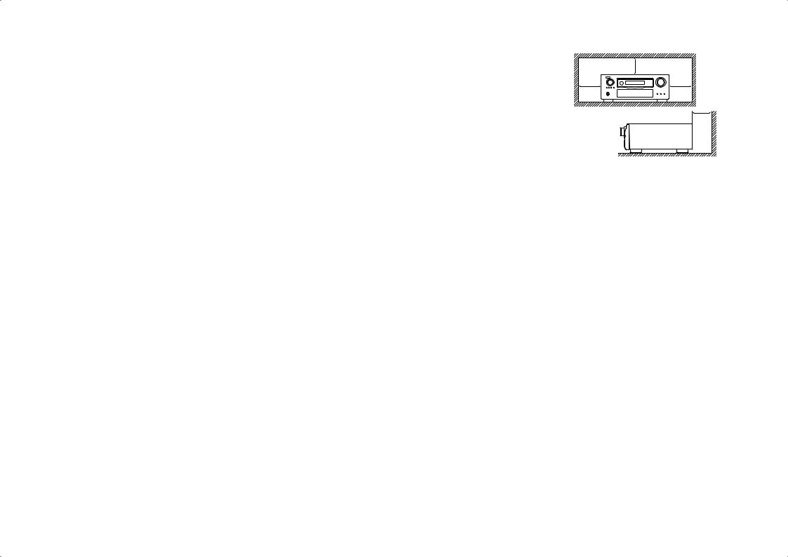
n CAUTIONS ON INSTALLATION
PRÉCAUTIONS D’INSTALLATION
|
z |
z |
z |
z
Wall
Paroi
zzFor proper heat dispersal, do not install this unit in a confined space, such as a bookcase or similar enclosure.
•More than 0.3 m (12 in.) is recommended.
•Do not place any other equipment on this unit.
zzPour permettre la dissipation de chaleur requise, n’installez pas cette unité dans un espace confiné tel qu’une bibliothèque ou un endroit similaire.
•Une distance de plus de 0,3 m (12 po) est recommandée.
•Ne placez aucun matériel sur cet appareil.
II

Getting started
Thank you for purchasing this DENON product. To ensure proper operation, please read these owner’s manual carefully before using the product. After reading them, be sure to keep them for future reference.
Contents
Getting started···············································································1
Accessories···················································································2 About this manual·········································································2
Features························································································2
Cautions on handling·····································································3
Simple version (Simple setup guide)···························4
Basic version··········································································14
Connections··················································································15
Important information··································································15 Connecting an HDMI-compatible device·····································16 Connecting a TV··········································································18 Connecting a Blu-ray Disc player·················································18 Connecting a DVD player····························································19
Connecting a set-top box (Satellite tuner/cable TV)·····················19 Connecting a digital video recorder·············································20 Connecting a digital camcorder···················································21 Connecting a control dock for iPod·············································21
Connecting an iPod or USB memory device to the USB port·····22
Connecting an antenna································································23 Connecting a record player··························································24 Connecting a CD player·······························································24 Component equipped with a DENON LINK connector···············25
Component with Multi-channel Output connectors····················25 Connecting a external power amplifier········································25 Connecting to a home network (LAN)·········································26 Connecting an external control device········································27
Playback (Basic operation)··························································28
Important information··································································28 Playing a Blu-ray Disc player/DVD player·····································29 Playing a CD player······································································30 Playing an iPod®·········································································30
Tuning in radio stations·······························································33
Playing a network audio······························································37
Playing a USB memory device····················································48
Selecting a listening mode (Surround Mode)···························50
Standard playback·······································································50
DENON original surround playback·············································52
Stereo playback···········································································52 Direct playback············································································52 Pure direct playback····································································52
Advanced version ·······························································53
Speaker installation/connection (Advanced connection)········54
Install···························································································54
Connect·······················································································56 Set up speakers···········································································63 Playback (Advanced operation)··················································65
Convenient functions··································································65
Playback in ZONE2/ZONE3 (Separate room) ···························72
Audio output················································································72 Video output················································································72 Playback······················································································73
Menu Operation··········································································73 Quick select function···································································74 Sleep timer function····································································74 How to make detailed settings··················································75
Menu map···················································································75 Examples of menu screen displays·············································76 Examples of menu and front display···········································77 Inputting characters ····································································78
SOURCE SELECT········································································80 AUDIO/VIDEO ADJUST·······························································86 MANUAL SETUP·········································································93 INFORMATION·········································································107
Operating the connected devices by remote control unit·····108
Operating the main remote control unit····································108 Operating the sub remote control unit······································115
Information···········································································119
Part names and functions·························································120
Front panel················································································120
Display·······················································································121 Rear panel·················································································122
Remote control unit···································································123 Other information······································································125
Trademark information······························································125 Surround····················································································126 Relationship between video signals and monitor output··········131
Explanation of terms·································································132
Troubleshooting·········································································135
Resetting the microprocessor···················································138 Specifications·············································································139
version Simple
version Basic
version Advanced
Information
1
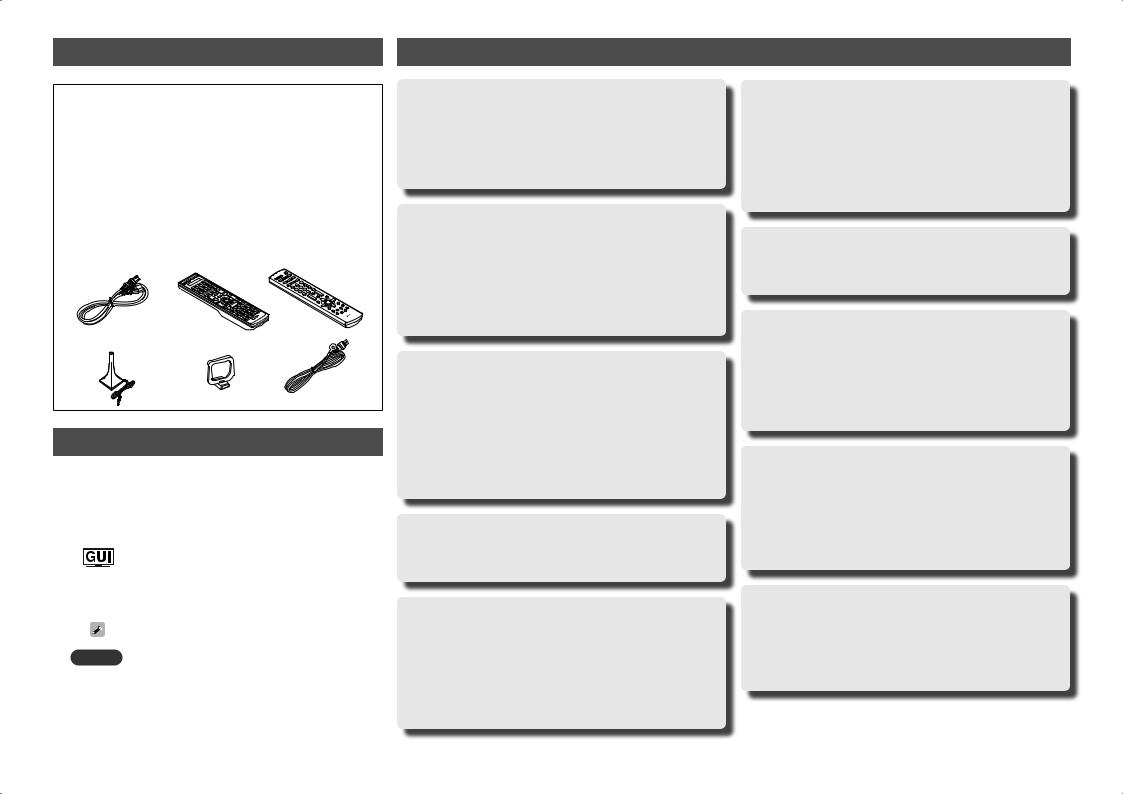
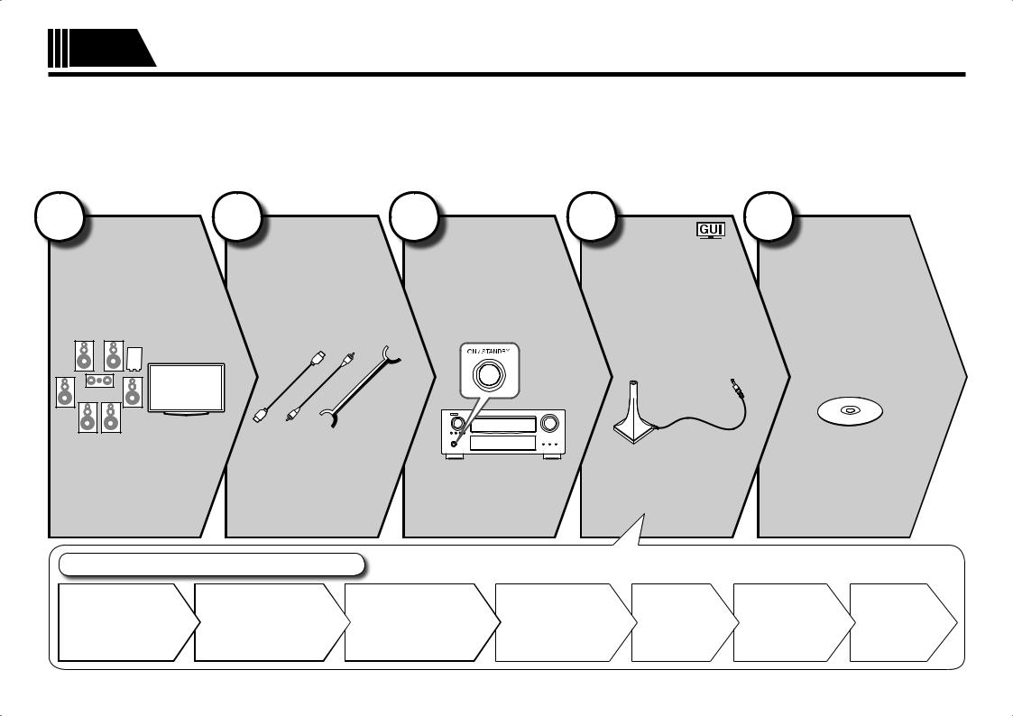
Accessories
Check that the following parts are supplied with the product.
q Owner’s manual ...................................................................... |
|
1 |
w Warranty (for North America model only)................................ |
1 |
|
e Service network list................................................................. |
|
1 |
r Power cord (Cord length: Approx. 6.2 ft / 1.9 m) .................... |
1 |
|
t Main remote control unit (RC-1145) ........................................ |
1 |
|
y R6/AA batteries (for RC-1145) ................................................. |
2 |
|
u Sub remote control unit (RC-1148).......................................... |
1 |
|
i R03/AAA batteries (for RC-1148)............................................. |
2 |
|
o Setup microphone |
|
|
(DM-A409, Cord length: Approx. 19.7 ft / 6.0 m) .................... |
1 |
|
Q0AM loop antenna (for HD Radio broadcasts) ........................... |
1 |
|
Q1FM indoor antenna (for HD Radio broadcasts) ........................ |
1 |
|
r |
t |
u |
o |
Q0 |
Q1 |
About this manual
nOperation buttons
The operations described in this manual are based mainly on remote control operation.
nSymbols
Items for which this mark is indicated at the title can be operated from the GUI menu.
We recommend performing such operations from the GUI menu.
vThis symbol indicates a reference page on which related information is described.
|
This symbol indicates a supplementary information |
|
|
and tips for operations. |
|
NOTE |
This symbol indicates a supplementary information |
|
and tips for operations. |
||
|
nIllustrations
Note that the illustrations in these instructions are for explanation purposes and may differ from the actual unit.
Features
Fully Discrete, identical quality and power for all 9 channels (170 W x 9ch)
The unit is equipped with a power amplifier that reproduces highfidelity sound in surround mode with equal quality and power for all channels, true to the original sound.
The power amplifier circuit adopts a discrete-circuit configuration that achieves high-quality surround sound reproduction.
Supports HDMI 1.4a with 3D, ARC, Deep Color, x.v.Color , Auto Lipsync and HDMI control function
This unit can output 3D video signals input from a Blu-ray Disc player to a TV that supports a 3D system. This unit also supports the ARC (Audio Return Channel) function, which reproduces TV sound with this unit via an HDMI cable used for connecting the
unit and a TVz1.
z1 The TV should support the ARC function.
Internet radio, music and photo streaming via networkz2
This unit can playback audio files and still images such as photographs that are stored on your computer via a network. You can also listen to internet radio and a whole host of other online
musicz3 that uses network technology.
z2 An internet connection is required.
z3 You may be required to sign a service agreement with the companies that provide particular services.
7-HDMI inputs and 2-outputs
The unit is equipped with 7 HDMI input connectors for connecting devices with HDMI connectors, such as a Blu-ray Disc player, game machine, HD video camera, etc.
Dolby Volume
Dolby Volume measures, analyzes, and maintains volume levels based on how people perceive sound. It examines a variety of audio parameters to maintain consistent playback levels whether switching between channels or between multiple source inputs. A sophisticated combination of spectraland time-based loudness analysis enables it to quickly and properly correct level differences without creating compression artifacts or undesirable pumping in the audio signal.
DENON LINK 4th support
When you connect this unit to a Denon Blu-ray disc player that has DENON LINK 4th support, you can enjoy HD audio of the highest quality. The master clock that operates the D/A converter of this unit is transmitted to the Blu-ray disc player, enabling the integrated circuitry to be operated while sharing the same clock in order to achieve digital audio transmission with negligible jitter. Sound localization becomes clearer and a greater sense of space is produced in the sound images.
High definition audio support
The unit is equipped with a decoder which supports high-quality digital audio format for Blu-ray Disc players such as Dolby TrueHD, DTS-HD Master Audio, etc.
Audyssey MultEQ® XT 32
Audyssey MultEQ corrects both time and frequency response problems in the listening area so that every listener can enjoy music and movie with the optimum sounds. It performs a fully automated surround system setup. The unit is equipped Audyssey MultEQ XT 32 that can correct much higher details, particularly in the bass range of the speakers. The high resolution correction reproduces much clearer surround sound.
Discrete subwoofers and Audyssey multiple subwoofer calibration
The unit has two subwoofer output capability and can adjust the level and delay for each subwoofer individually. Audyssey multiple subwoofer calibration optimizes the level, delay, and frequency response blending of two subwoofers. It eliminates the phase cancellations between two subwoofers. The optimized sound reporoduces more powerful sound.
Audyssey DSX™
This unit is equipped with Audyssey DSX processor. By connecting front height speakers to this unit and playing back through Audyssey DSX, you can experience a more powerful playback expression in the height audio range. By connecting front wide speakers, you can experience a more powerful playback expression in the wide audio range.
2
Features
Easy to use, Graphical User Interface
This unit is equipped with an easy to see “Graphical User Interface” that uses menu displays and levels. The use of level displays increases operability of the this unit.
All sources are up-scaled to 1080p
The unit is provided with an HDMI video up-scaling function that converts an analog video signal input to the unit to a 1080p (HD resolution) signal and supplies it to a TV via the HDMI connector. This enables the unit and a TV connected with a single HDMI cable and any video source to be reproduced precisely with HD level of quality.
Direct play for iPod® and iPhone® via USB
Music data from an iPod can be played back if you connect the USB cable supplied with the iPod via the USB port of this unit, and also an iPod can be controlled with the remote control unit for this unit.
When an iPod is connected, merely pressing iPod PLAY on the main unit or remote control unit starts playback of music from the iPod.
Simultaneous playback on two HDMI channels
This unit is equipped with two HDMI MONITOR outputs. You can connect one output to a projector and the other output to a TV for simultaneous signal outputs.
Cautions on handling
•Before turning the power switch on
Check once again that all connections are correct and that there are no problems with the connection cables.
•Power is supplied to some of the circuitry even when the unit is set to the standby mode. When going on vacation or leaving home for long periods of time, be sure to unplug the power cord from the power outlet.
•About condensation
If there is a major difference in temperature between the inside of the unit and the surroundings, condensation (dew) may form on the operating parts inside the unit, causing the unit not to operate properly.
If this happens, let the unit sit for an hour or two with the power turned off and wait until there is little difference in temperature before using the unit.
•Cautions on using mobile phones
Using a mobile phone near this unit may result in noise. If that occurs, move the mobile phone away from this unit when it is in use.
•Moving the unit
Turn off the power and unplug the power cord from the power outlet. Next, disconnect the connection cables to other system units before moving the unit.
•About Care
•Wipe the cabinet and control panel clean with a soft cloth.
•Follow the instructions when using a chemical cleaner.
•Benzene, paint thinner or other organic solvents as well as insecticide may cause material changes and discoloration if brought into contact with the unit, and should therefore not be used.
version Simple
version Basic
version Advanced
Information
3
Simple Simple version (Simple setup guide)
version
Here, we explain the entire setup procedure, from unboxing the unit to using it in a home theater.
The “Simple version” section provides the speaker installation, connection, and setup methods for the 7.1-channel system with surround back speakers. For the installing, connecting, and setup methods of speakers other than the 7.1-channel system (with surround back speakers), see page 54.
nBefore connecting the unit, turn off the power to all devices.
nFor operation of the connected devices, refer to the user manuals for each device.
1
back
(vpage 13)
Blu-ray Disc in
sound.
Set up speakers (Audyssey® Auto Setup)
STEP 4 |
STEP 5 |
STEP 6 |
Calculation |
Check |
Store |
Finish |
1 Install |
1 |
2 |
3 |
4 |
5 |
2 Connect |
1 |
2 |
3 |
4 |
5 |
|
|
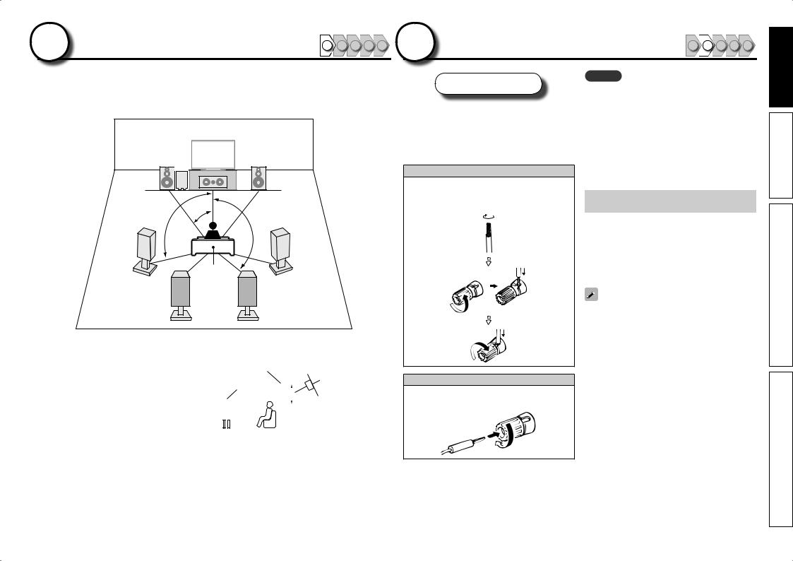
This unit can perform 2.0 to 11.2-channel surround playback. This page provides the speaker installation procedure for the 7.1-channel playback using surround back speakers as an example.
FL SW |
FR |
|
C |
|
|
22 – 30˚ |
|
90 – 110˚ |
135 – 150˚ |
|
|
|
SL |
|
SR |
|
|
Listening |
|
|
position |
SBL SBR
FL Front speaker (L) FR Front speaker (R) C Center speaker SW Subwoofer
SL Surround speaker (L) SR Surround speaker (R)
SBL Surround back speaker (L) SBR Surround back speaker (R)
•Install the surround speakers in a position 2 to 3 ft (60 to 90 cm) higher than ear level.
|
|
|
|
Surround |
|
|
||||||
|
Front |
speaker |
|
Surround back |
||||||||
|
|
|
|
|
|
|
|
|
||||
|
speaker |
|
|
|
|
|
|
|
|
speaker |
||
2 – 3 ft / |
|
|
|
|||||||||
|
|
|
|
|
• Point slightly |
|||||||
|
|
|
|
|
|
|
||||||
|
|
|
|
60 – 90 cm |
|
|
|
|||||
|
|
|
|
|
|
|
|
|
|
|
|
downwards |
|
|
|
|
|
|
|
|
|
|
|
|
|
|
|
|
|
|
|
|
|
|
|
|
|
|
GViewed from the sideH
Speakers
Carefully check the left (L) and right (R) channels and + (red) and – (black) polarities on the speakers being connected to the this unit, and be sure to interconnect the channels and polarities correctly.
Connecting the speaker cables
Peel off about 0.03 ft/10 mm of sheathing from the tip of the speaker cable, then either twist the core wire tightly or terminate it.
When using a banana plug
Tighten the speaker terminal firmly before inserting the banana plug.
NOTE
•Connect so that the speaker cable core wires do not protrude from the speaker terminal. The protection circuit may be activated if the core wires touch the rear panel or if the + and – sidestoucheachother(vpage134“Protection
Circuit”).
•Never touch the speaker terminals while the power supply is connected. Doing so could result in electric shock.
•Use speakers with the speaker impedances shown below.
Speaker terminals |
Speaker |
|
impedance |
||
|
||
FRONT |
|
|
CENTER |
|
|
SURROUND |
4 – 16 Ω |
|
SURR. BACK / AMP ASSIGN |
||
|
||
F.HEIGHT / AMP ASSIGN |
|
|
F.WIDE / AMP ASSIGN |
|
Use speakers where one speaker has an impedance of 4 to 16 Ω.
When using a speaker with impedance of 4 Ω or 6 Ω, make sure to set the “Speaker Impedance” in the menu (vpage 98) to “6 Ω/ohms” or “4 Ω/ ohms”.
The “Simple version” section provides the speaker installation, connection, and setup methods for the 7.1-channel system with surround back speakers. |
5 |
For the installing, connecting, and setup methods of speakers other than the 7.1-channel system (with surround back speakers), see page 54 . |
|
version Simple
version Basic
version Advanced
Information
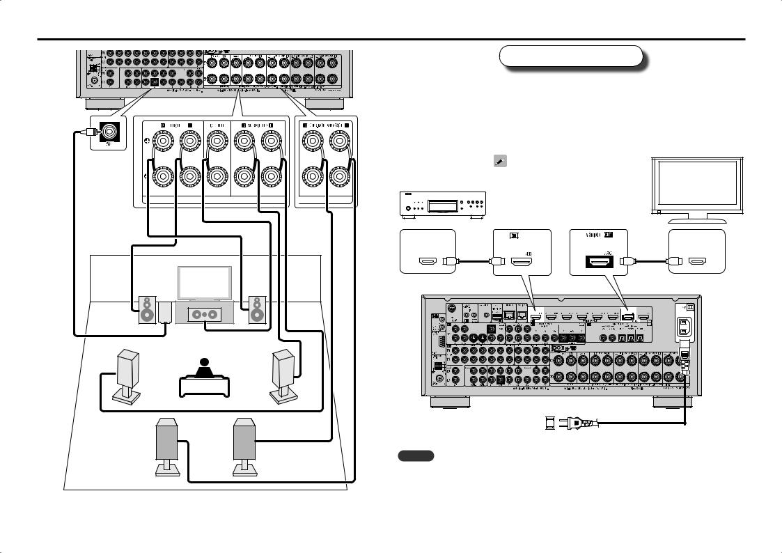
Connect
Blu-ray Disc player and TV
Use only an HDMI (High Definition Multimedia Interface) cable that bears the HDMI logo (a genuine HDMI product). Using a cable without the HDMI logo (a non-genuine HDMI product) may result in abnormal playback.
When outputting Deep Color or 1080p, etc., we recommend you use a “High Speed HDMI cable” or a “High Speed HDMI cable with Ethernet”for enhanced high-quality playback.
TV
Blu-ray Disc player
Audio cable (sold separately)
If your TV does not support the ARC function (vpage 16), make the audio connection referring to “Connecting a TV” (vpage 18). TV sound can be played on this unit.
HDMI |
HDMI |
OUT |
IN |
FL SW |
FR |
|
C |
HDMI cable |
HDMI cable |
(sold separately) |
(sold separately) |
Subwoofer with |
Speaker cables |
|
|
(sold separately) |
|
|
|
built-in amplifier |
|
|
|
|
|
|
|
SL |
|
SR |
|
|
|
To household power outlet |
|
|
|
(AC 120 V, 60 Hz) |
Power cord |
|
|
|
|
|
|
|
(supplied) |
SBL |
SBR |
NOTE |
|
|
|
• Do not plug in the power cord until all connections have been completed. |
|
|
|
• Do not bundle power cords together with connection cables. Doing so can result in humming or noise. |
|
6 |
The “Simple version” section provides the speaker installation, connection, and setup methods for the 7.1-channel system with surround back speakers. |
|
For the installing, connecting, and setup methods of speakers other than the 7.1-channel system (with surround back speakers), see page 54 . |
|
|
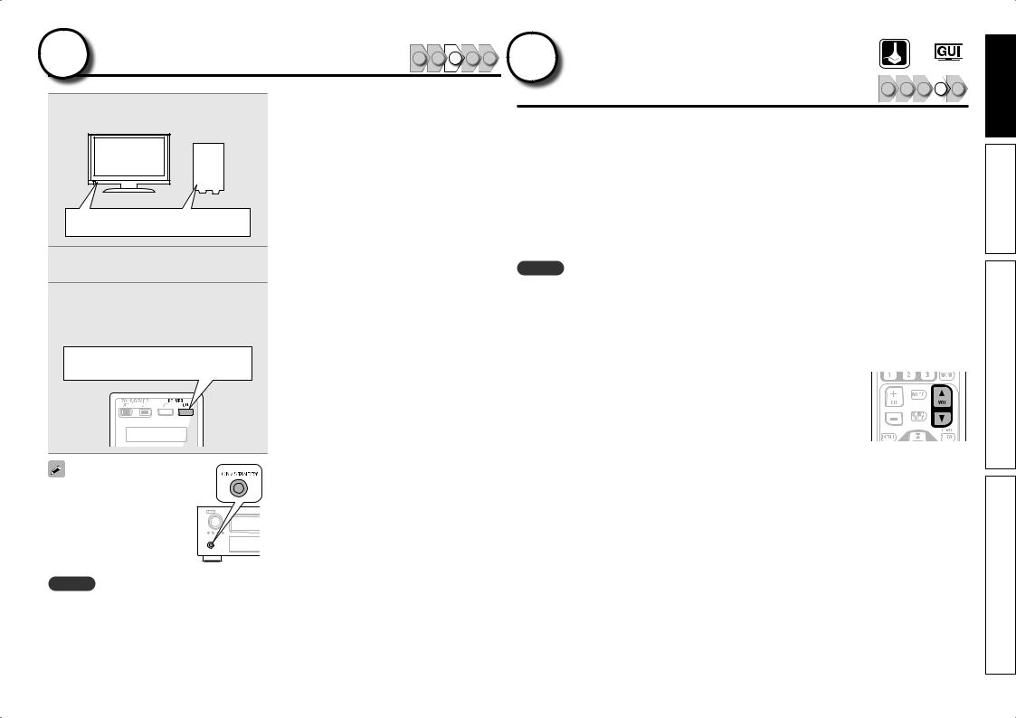
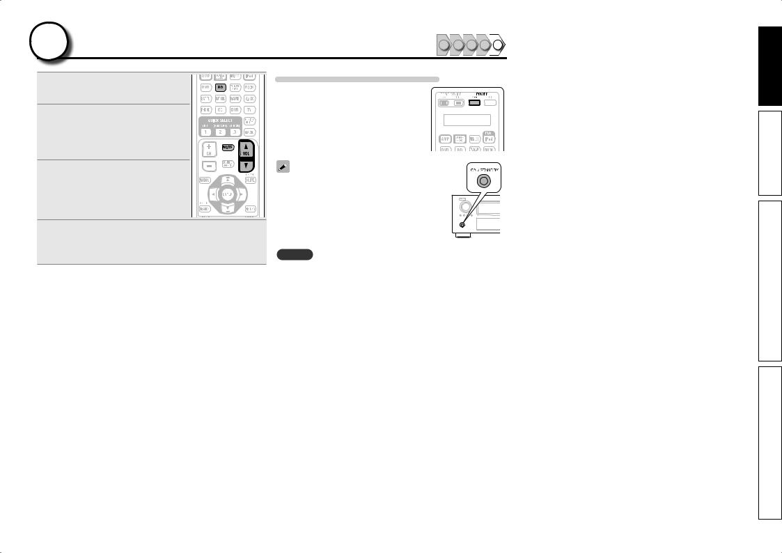
3Turn on power
1Turn on the TV and subwoofer power.
2
3 Press POWER ON to turn on power to the this unit.
The power indicator flashes green and the power turns on.
Power on
You can also switch the power
to standby by pressing ON/STANDBY on the main unit.
NOTE
Before you use the remote control unit for the first time, be sure to insert the batteries (vpage 124 “Inserting the batteries”).
1 2 3 4 5 4 Set up speakers |
|
|
|
|
|
(Audyssey® Auto Setup) |
1 |
2 |
3 |
4 |
5 |
|
The acoustic characteristics of the connected speakers and listening room are measured and the optimum settings are made automatically. This is called “Audyssey Auto Setup”.
To perform measurement, place the setup microphone in multiple locations all around the listening area. For best results, we recommend you measure in six or more positions, as shown in the illustration (up to eight positions).
•When performing Audyssey Auto Setup, MultEQ® XT 32/Dynamic EQ®/Dynamic Volume® functions become active (vpage 89, 90).
•To set up the speakers manually, use “Speaker Setup” (vpage 93) on the menu.
NOTE
•Make the room as quiet as possible. Background noise can disrupt the room measurements. Close windows, silence cell phones, televisions, radios, air conditioners, fluorescent lights, home appliances, light dimmers, or other devices as measurements may be affected by these sounds.
•Cell phones should be placed away from all audio electronics during the measurement process as Radio Frequency Interference (RFI) may cause measurement disruptions (even if the cell phone is not in use).
•Do not unplug the setup microphone from the main unit until Audyssey Auto Setup is completed.
•Do not stand between the speakers and setup microphone or allow obstacles in the path while
 the
the
measurements are being made. This will cause inaccurate readings.
• Loud test sounds may be played during Audyssey Auto setup. This is part of normal operation. If there is background noise in room, these test signals will increase in volume.
• Operating VOL dfduring the measurements will cancel the measurements.
• Measurement cannot be performed when headphones are connected.
7
version Simple
version Basic
version Advanced
Information
Set up speakers (Audyssey® Auto Setup)
About setup microphone placement
•Measurements are performed by placing the setup microphone successively at multiple positions throughout the entire listening area, as shown in GExample qH. For best results, we recommend you measure in six or more positions, as shown in the illustration (up to eight positions).
•Even if the listening environment is small as shown in GExample wH, measuring at multiple points throughout the listening environment results in more effective correction.
|
|
GExample qH |
|
|
|
GExample wH |
||
|
|
FL SW C |
FR |
|
|
|
FL SW C |
FR |
|
( |
: Measuring positions) |
|
|
( |
: Measuring positions) |
||
SL |
|
*M |
|
SR |
SL |
|
*M |
SR |
|
|
|
|
|
||||
|
|
SBL |
SBR |
|
|
|
SBL |
SBR |
FL |
Front speaker (L) |
|
|
SL |
Surround speaker (L) |
|||
FR |
Front speaker (R) |
|
|
SR |
Surround speaker (R) |
|||
C |
Center speaker |
|
|
SBL Surround back speaker (L) |
||||
SW Subwoofer |
|
|
SBR Surround back speaker (R) |
|||||
About the main listening position (*M)
The main listening position is the position where listeners would normally sit or where one would normally sit alone within the listening environment. Before starting Audyssey Auto Setup, place the setup microphone in the main listening position. Audyssey MultEQ® XT 32 uses the measurements from this position to calculate speaker distance, level, polarity, and the optimum crossover value for the subwoofer.
About multiple subwoofer calibration
Audyssey multiple subwoofer calibration optimizes the level, delay, and frequency response blending of two subwoofers.
z To run Audyssey multiple subwoofer calibration you must select “Measure (2 spkrs)” in “Set up “Channel Select”” (vpage 64).
1 |
Prepare the setup microphone |
|
Mount the setup microphone on a tripod or stand and place it in the main listening position.
When placing the setup microphone, adjust the height of the sound receptor to the level of the listener’s ear.
Sound receptor
Setup microphone
NOTE
•Do not hold the setup microphone in your hand during measurements.
•Avoid placing the setup microphone close to a seat back or wall as sound reflections may give inaccurate results.
2 |
Set up the subwoofer |
If using a subwoofer capable of the following adjustments, set up the subwoofer as shown below.
n When using a subwoofer with a direct mode
Set the direct mode to “On” and disable the volume adjustment and crossover frequency setting.
n When using a subwoofer without a direct mode
Make the following settings:
•Volume : “12 o’clock position”
•Crossover frequency : “Maximum/Highest Frequency”
•Low pass filter : “Off”
•Standby mode : “Off”
3 |
Set up the remote control unit |
n Set up the zone mode
Press ZONE SELECT to switch the zone mode to M (MAIN ZONE).
The M indicator lights.
Press ZONE SELECT
n Set up the operation mode
Press AMP to set the remote control unit to AMPoperation mode.
Press AMP
8 |
The “Simple version” section provides the speaker installation, connection, and setup methods for the 7.1-channel system with surround back speakers. |
|
For the installing, connecting, and setup methods of speakers other than the 7.1-channel system (with surround back speakers), see page 54 . |
|
|
Set up speakers (Audyssey® Auto Setup)
STEP 1
Preparation
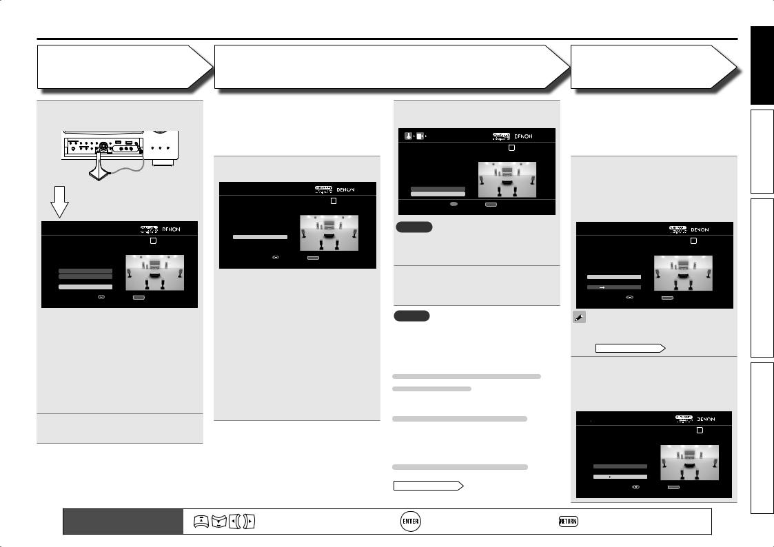
4 Connect the setup microphone to the SETUP MIC jack of this unit.
When the setup microphone is connected, the following screen is displayed.

 AUDYSSEY AUTO SETUP
STEP1 Preparation |
1 2 3 4 5 6 |
Connect the speakers and place them according to the recommendations in the manual,
Set the following items If necessary.
Amp Assign
Channel Select
Auto Setup Start
|
Enter |
RETURN Cancel |
|
|
Start Auto Setup |
|
|
This screen provides the |
method for setting |
||
up 7.1-channel playback using surround back speakers. For the method of setting up speakers other than the 7.1-channel system, select “Amp Assign” and perform step 3 and 7 of “Set up “Amp Assign”” (vpage 63).
If unused channels are set with “Channel Select”, measuring time can be shortened. Also, set “Channel Select” to measure two subwoofers. For setting, perform steps 9 to 14 of “Set up “Channel Select”” (vpage 64).
5 Use uito select “Auto Setup Start” and then press ENTER.
STEP 2
Detection & Measurement
(Main listening position)
•In STEP 2, you will perform measurements at the main listening position.
•This step automatically checks the speaker configuration and speaker size, and calculates the channel level, distance, and crossover frequency. It also corrects distortion in the listening area.
6 Select “Measure” and then press
ENTER.

 AUDYSSEY AUTO SETUP
STEP2 Detection & Measurement (main) |
1 2 3 4 5 6 |
|
Please place the microphone at ear |
|
|
height at main Iistening position. |
|
|
Measure |
|
|
|
|
|
Enter |
RETURN |
Cancel |
Start measurement. Output large test tone during measuring
qMeasure the subwoofer level
•To stop measuring, select “Cancel” and then press ENTER.
•When “Subwoofer” is set to “Skip” with “Channel Select”, this measurement is not taken, and the process proceeds to “w Measure each speaker”.
wMeasure each speaker
•Once the measurements in step q are complete, the measurements in step w start automatically.
•The measuring channel changes depending on the setting of “Set up “Amp Assign”” (vpage 63) and “Set up “Channel Select”” (vpage 64).
• Measurement requires several minutes.
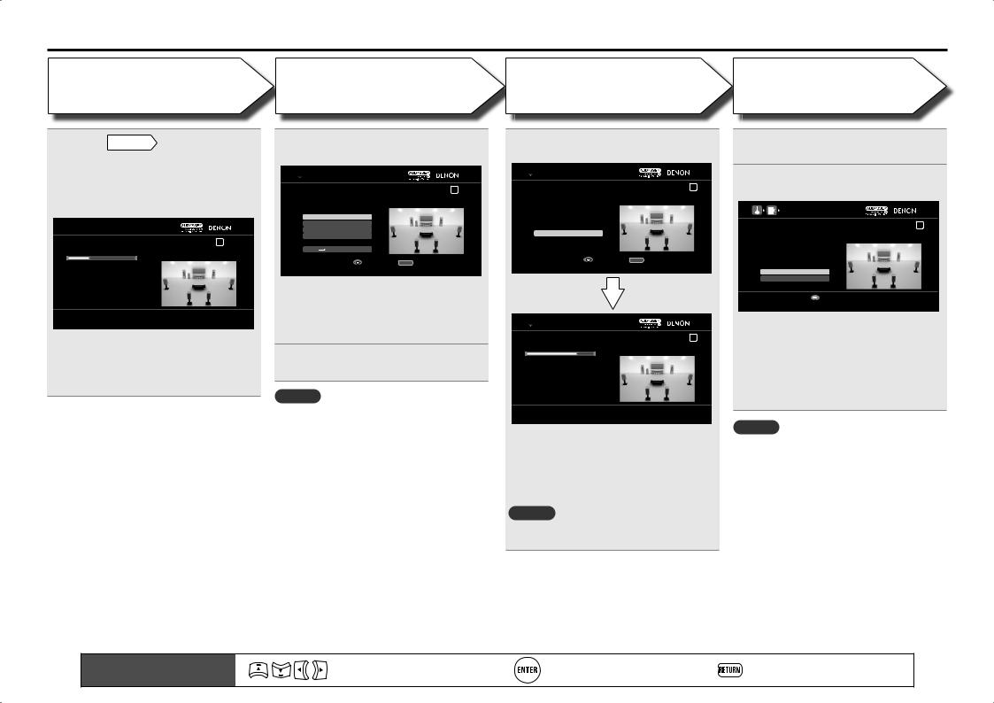
7 The detected speakers are displayed.
AUTO SETUP
|
Detection Check |
3 4 5 6 |
|||
|
Yes |
|
|
|
|
|
Yes |
|
|
|
|
Subwoofer |
1spkr |
|
|
|
|
Surround |
Yes |
|
|
|
|
Surround Back |
2spkrs |
|
|
|
|
Front Height |
No |
|
|
|
|
Retry
Next  Measurement


 Enter RETURN Cancel
Proceed to STEP 3 after checking speaker connection result
NOTE
If a connected speaker is not displayed, the speaker may not be connected correctly. Check the speaker connection.
8 Use uito select “Next →
Measurement” and then press
ENTER.
NOTE
If “Caution” is displayed:
Go to “Error messages” (vpage 11), check any related items, and perform the necessary procedures.
When performing Audyssey Auto Setup over again
Press uito select “Retry”, and then press ENTER.
When measuring has stopped
Press RETURN, to the “Cancel auto setup?” prompt
is displayed.
Press o to select “Yes”, then press ENTER.
Setting up the speakers again
Repeat the operation from step 4 of
STEP1 Preparation .
STEP 3
Measurement
(2nd – 8th listening position)
•In STEP 3, you will perform measurements at multiple positions (two to eight positions) other than the main listening position.
•You can achieve a more effective correction of distortion within the listening area by performing measurements at multiple positions.
9 Move the setup microphone to position 2, use ui to select
“Measure”, and then press ENTER.
The measurement of the second position starts. Measurements can be made in up to eight positions.

 AUDYSSEY AUTO SETUP
STEP3 Measurement(2nd-8th) |
|
1 2 3 4 5 6 |
Please place the microphone at ear |
|
|
height at 2nd Iistening position. |
|
|
Measure |
|
|
Next Calculation |
|
|
|
|
|
Enter |
RETURN |
Cancel |
Start measurement. Output large test tone during measuring
If you want to omit measurements from the next position onward, select “Next → Calculation”. (Go to STEP4 Calculation )
10Repeatto 8. step 9, measuring positions 3
When measurement of position 8 is completed, a “Measurements finished.” message is displayed.

 AUDYSSEY AUTO SETUP
STEP3 Measurement(2nd-8th) |
1 2 3 4 5 6 |
||
Measurements finished. |
|
||
Retry |
|
||
Next |
|
Calculation |
|
|
|
||
|
|
|
|
|
|
Enter |
RETURN Cancel |
Proceed to STEP4 (Calculation) |
|
||
Remote control operation |
Move the cursor |
Confirm the setting |
Return to previous menu |
9 |
|
buttons |
(Up/Down/Left/Right) |
||||
|
|
|
version Simple
version Basic
version Advanced
Information
Set up speakers (Audyssey® Auto Setup)
STEP 4
Calculation
11On the STEP3 screen, use ui to select “Next → Calculation”, and then press ENTER.
Measuring results are analyzed, and the frequency response of each speaker in the listening room is determined.

 AUDYSSEY AUTO SETUP
STEP4 Calculation |
1 2 3 4 5 6 |
Now calculating...Please wait. 27%
•Analysis takes several minutes to complete. The time required for this analysis depends on the number of speakers connected.
The more connected speakers there are, the longer it takes to perform analysis.
STEP 5
Check
12Use ui to select the item you want to check, and then press ENTER.

 AUDYSSEY AUTO SETUP
STEP5 Check |
1 2 3 4 5 6 |
Check processing results. |
|
To proceed,press “Next”. |
|
Spkr Config Check |
|
Distance Check |
|
Ch.Level Check |
|
Crossover Check |
|
Next Store |
|
|
|
Enter |
RETURN Cancel |
Select item to check |
|
•Subwoofers may measure a greater reported distance than the actual distance due to added electrical delay common in subwoofers.
•If you want to check another item, press
RETURN.
13Use ui to select “Next → Store” and then press ENTER.
NOTE
•If the result differs from the actual connection status, or if “Caution!” is displayed, see “Error messages” (vpage 11). Then carry out Audyssey Auto Setup again.
•If the result still differs from the actual connection status after remeasurement or the error message
still appears, it is possible that the speakers are not connected properly. Turn this unit off, check the speaker connections and repeat the measurement process from the beginning.
•If you change speaker positions or orientation, perform Audyssey Auto Setup again to find the optimal equalizer settings.
STEP 6
Store
14Select “Store” and then press ENTER.
Save the measurement results.

 AUDYSSEY AUTO SETUP
STEP6 Store |
|
1 2 3 4 5 6 |
Press “Store” to store calculation results. |
|
|
Store |
|
|
|
|
|
Enter |
RETURN |
Cancel |
Apply and store measurement result |
|
|

 AUDYSSEY AUTO SETUP
STEP6 Store |
1 2 3 4 5 6 |
Now storing... Please wait. 78%
•Saving the results requires about 20 seconds.
•If the measuring results are not to be saved, press RETURN. A message “Cancel auto setup?” will be displayed. Press o then select “Yes”. All the measured Audyssey Auto Setup data will be erased.
NOTE
During saving of measurement results, be sure not to turn off the power.
Finish
15Unplug the setup microphone from the unit’s SETUP MIC jack.
16Set Dynamic Volume®.
|
AUDYSSEY AUTO SETUP |
Finish |
1 2 3 4 5 6 |
Storing complete.
Auto Setup is now finished.
Please unplug microphone.
Turn on Dynamic Volume?
Yes
No


 Exit
Exit
Turn Dynamic Volume on and exit Auto Setup
•For details of Dynamic Volume settings, see page 90.
n When turning Dynamic Volume on
Use uto select “Yes“, and then press ENTER.
• The unit automatically enters “Evening” mode.
n When turning Dynamic Volume off
Use i to select “No“, and then press ENTER.
NOTE
•After performing Audyssey Auto Setup, do not change the speaker connections or subwoofer volume. In event of a change, perform Audyssey Auto Setup again.
•After performing Audyssey Auto Setup with two subwoofers, do not change the channel distances and levels of both subwoofers.
10 |
Remote control operation |
Move the cursor |
Confirm the setting |
Return to previous menu |
|
buttons |
(Up/Down/Left/Right) |
||||
|
|
|
Error messages
An error message is displayed if Audyssey® Auto Setup could not be completed due to speaker placement, the measurement environment, etc. If this happens, check the relevant items, be sure to take the necessary measures, then perform Audyssey Auto Setup over again.
NOTE
Be sure to turn off the power before checking speaker connections.
|
|
Examples |
Error details |
Measures |
|
|
|
|
|
|
|
|
|
|
|
• Correct measurement is not possible due to |
• When using a subwoofer with built-in |
|
AUDYSSEY AUTO SETUP |
|
|||
|
|
inappropriate subwoofer volume. |
amplifier (active type), use “SW Level |
||
|
Caution! |
1 2 3 4 5 6 |
|
||
|
|
|
Matching” to adjust the subwoofer volume |
||
|
The subwoofer’s level is too high or low. Please select “SW |
|
|
(vpage 11 “Subwoofer level error message |
|
|
Level Matching” and adjust the level of your subwoofer unit. |
|
|
||
|
If you do not want to use the |
|
|
and how to adjust”). |
|
|
subwoofer, select “Skip”. |
|
|
||
|
|
|
|
|
• When using a subwoofer without a built-in |
|
SW Level Matching |
|
|
amplifier, select “Skip”, and then press |
|
|
Skip |
|
|
|
ENTER. |
|
|
|
|
|
|
|
AUDYSSEY AUTO SETUP |
|
• The connected setup microphone is broken, |
• Connect the included setup microphone to |
|
|
|
or a device other than the supplied setup |
the SETUP MIC jack of this unit. |
||
|
|
|
|
||
|
|
Caution! |
|
||
|
|
|
microphone is connected. |
|
|
|
No microphone or speaker |
|
|
||
|
|
• Not all speakers could be detected. |
|
||
|
|
|
|
|
|
|
|
|
|
• The front L speaker was not properly |
• Check the speaker connections. |
|
|
Retry |
|
detected. |
|
|
|
|
|
|
|
|
|
|
|
|
|
|
|
RETURN Cancel |
|
|
|
|
AUDYSSEY AUTO SETUP |
|
• There is too much noise in the room for |
• Either turn off any device generating noise |
|
|
|
accurate measurements to be made. |
or move it away. |
||
|
|
|
|
||
|
|
Caution! |
|
||
|
|
|
|
• Perform again when the surroundings are |
|
|
Ambient noise is too high |
|
|
||
|
|
|
quieter. |
||
|
|
or Level is too low |
|
|
|
|
|
|
|
• Speaker or subwoofer sound is too low for |
• Check the speaker installation and the |
|
|
Retry |
|
accurate measurements to be made. |
direction in which the speakers are facing. |
|
|
|
|
• Adjust the subwoofer’s volume. |
|
|
|
|
|
|
|
|
|
|
|
|
|
|
|
RETURN Cancel |
|
|
|
|
AUDYSSEY AUTO SETUP |
|
• The displayed speaker could not be detected. |
• Check the connections of the displayed |
|
|
|
|
speaker. |
||
|
|
|
|
|
|
|
Caution! |
1 2 3 4 5 6 |
|
|
|
|
|
|
|
||
|
Front R |
None |
|
|
|
|
Retry |
|
|
|
|
|
|
|
|
|
|
|
|
RETURN Cancel |
|
|
|
|
AUDYSSEY AUTO SETUP |
|
• The displayed is connected with the |
• Check the polarities of the displayed |
|
|
|
polarities reversed. |
speaker. |
||
|
|
|
|
||
|
Caution! |
1 2 3 4 5 6 |
|
||
|
|
|
• For some speakers, this error message may |
||
|
Front L |
Phase |
|
|
|
|
|
|
|
|
be displayed even if the speaker is properly |
|
|
|
|
|
connected. If you are sure the connection is |
|
|
|
|
|
correct, press ui to select “Skip”, then |
|
Retry |
|
|
|
press ENTER. |
|
Skip |
|
|
|
|
|
|
RETURN Cancel |
|
|
|
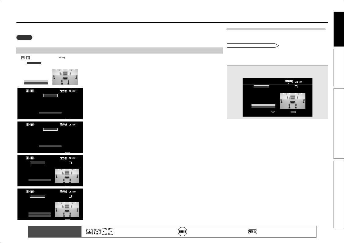
Subwoofer level error message and how to adjust
The optimal level of each subwoofer channel for Audyssey Auto Setup measurement is 75 dB. During subwoofer level measurement (“Set up speakers (Audyssey® Auto Setup),
STEP2 Detection & Measurement ” (vpage 9), 6 – q), an error message is displayed when one level of subwoofers is outside the 72 – 78 dB range. When using a subwoofer with built-in amplifier (active type), adjust the subwoofer volume so that the subwoofer level is within the 72 to 78 dB range.
1 Select “SW Level Matching” and then press ENTER.

 AUDYSSEY AUTO SETUP
Caution! |
1 2 3 4 5 6 |
The subwoofer’s level is too high or low. Please select “SW Level Matching” and adjust the level of your subwoofer unit. If you do not want to use the
subwoofer, select “Skip”.
SW Level Matching
Skip
|
Enter |
RETURN |
Cancel |
|
|
Proceed to subwoofer volume adjustment item |
|
|
|
|
|
|
|
|
Remote control operation |
Move the cursor |
Confirm the setting |
Return to previous menu |
11 |
|
buttons |
(Up/Down/Left/Right) |
||||
|
|
|
version Simple
version Basic
version Advanced
Information
|
|
|
|
|
|
|
Error messages |
|
|
|
|
|
|
|
|
||
|
|
|
|
|
|
|
||
Select “SW Test Start” and then press ENTER. |
|
Adjust the volume control on your subwoofer so that |
||||||
2 Subwoofer level measurement begins. |
|
|
|
3 the measured level is within the 72 to 78 dB range. |
||||
During measuring, a “Testing …” message is displayed. |
|
|
|
|
|
|||
The measured level appears on the level indicator after about |
|
|
AUDYSSEY AUTO SETUP |
|
|
|||
3 to 5 seconds. |
|
|
|
|
Subwoofer Level Matching |
1 2 3 4 5 6 |
|
|
|
|
|
|
|
|
Please adjust the level of your active subwoofer unit |
||
|
AUDYSSEY AUTO SETUP |
|
|
|
|
so that the level Indicates approx. 75dB |
|
|
|
|
|
|
|
|
|
|
|
|
|
|
|
|
|
Stop |
|
|
|
Subwoofer Level Matching |
1 2 3 4 5 6 |
|
|
|
|
|
|
Please place the microphone at ear height at main listening position, then push ENTER.
SW Test Start
dB
Next


 Enter RETURN Cancel Start measurement Output test tone from subwoofer
Blue 
 73.9dB


 Enter
Enter
Change from red to blue when level matches
•If the measured level is within the 72 to 78 dB range, the level indicator is blue.

 AUDYSSEY AUTO SETUP
Subwoofer Level Matching |
1 2 3 4 5 6 |
Please adjust the level of your active subwoofer unit so that the level Indicates approx. 75dB
Stop
Red 
 79.1dB


 Enter
Enter
Change from red to blue when level matches
•If the measured level is outside the 72 to 78 dB range, the level indicator is red.
•When measuring stops, press ENTER.
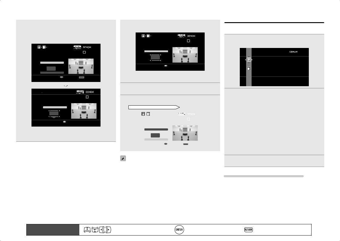
4 When the measured level is within the 72 to 78 dB range, press ENTER.
Select “Next” and then press ENTER. |
|||
5 Proceed to “Set up speakers (Audyssey® Auto Setup), |
|||
STEP2 Detection & Measurement |
” (vpage 9), 6 – w. |
||
|
|
|
|
|
AUDYSSEY AUTO SETUP |
|
|
|
Subwoofer Level Matching |
1 2 3 4 5 6 |
|
|
After adjustment, push “Next”. |
|
|
|
SW Test Start |
|
|
|
dB |
|
|
|
Next |
|
|
|
Enter |
RETURN Cancel |
|
|
Proceed to next measurement |
|
|
|
|
|
|
When you use two subwoofers, adjust each subwoofer so that the volume levels of Subwoofer 1 and Subwoofer 2 are appropriate for your needs.
Parameter Check
This function enables you to check the measurement results and equalizer characteristics after Audyssey Auto Setup.
1 Use ui to select “Parameter Check” and then press ENTER or p.
 PARAMETER CHECK
Spkr Config Check
Distance Check
Ch. Level Check
Crossover Check
EQ Check
Restore
Check auto setup measurement results
2 Use ui to select the item you want to check, then press ENTER or p.
Measurement results for each speaker are displayed.
|
Check the speaker configuration. |
|
Speaker Config Check |
||
|
||
|
Check the distance. |
|
Distance Check |
||
|
||
|
Check the channel level. |
|
Ch. Level Check |
||
|
||
|
Check the crossover frequency. |
|
Crossover Check |
||
|
||
|
Check the equalizer. |
|
EQ Check |
||
|
•If “EQ Check” is selected, press ui to select equalizing curve
(“Audyssey” or “Audyssey Flat”) to be checked, and then press
ENTER or p.
Use ui to switch the display between the different speakers.
3 Press RETURN.
The confirmation screen reappears. Repeat steps 2.
Retrieving Audyssey Auto Setup settings
If you set “Restore” to “Yes”, you can return to Audyssey Auto Setup measurement result (value calculated at the start by MultEQ® XT 32) even when you have changed each setting manually.
12 |
Remote control operation |
Move the cursor |
Confirm the setting |
Return to previous menu |
|
buttons |
(Up/Down/Left/Right) |
||||
|
|
|
5 Play back disc |
1 |
2 |
3 |
4 |
5 |
|
1 PressBD toswitchaninputsource for a player used for playback.
2 Play the component connected to this unit.
Make the necessary settings on the player (language setting, subtitles setting, etc.) beforehand.
3 Adjust the sound volume.
VOL d |
........................................... Volume up |
VOL f...................................... |
Volume down |
MUTE.................................................. |
Muting |
4 Set the listening mode.
Set the listening mode according to the playback contents (cinema, music, etc.) or according to your liking (vpage 50 “Selecting a listening mode (Surround Mode)”).
When power is switched to standby
Press POWER OFF.
GPower indicator status in standby modeH
•Normal standby : Off
•When “HDMI Control” – “Control” is set to
“ON” : Red
• When “Network Standby” is set to “ON” : Red
You can also switch the power to standby by pressing ON/STANDBY on the main unit.
NOTE
During power standby, a minimal amount of power is consumed. To totally cut off the power, remove the power cord from the power outlet.
version Simple
version Basic
version Advanced
Information
13
Basic version
Basic version
Here, we explain the connections and basic operation methods for this unit.
FConnections vpage 15
FPlayback (Basic operation) vpage 28
FSelecting a listening mode (Surround Mode) vpage 50
nnRefer to the pages indicated below for information on connecting and playing back the various media and external devices.
|
Audio and Video |
Connection |
Playback |
|
|
|
|
|
TV |
vpage 17, 18 |
– |
|
|
|
|
|
Blu-ray Disc player |
vpage 17, 18 |
vpage 29 |
|
|
|
|
|
DVD player |
vpage 17, 19 |
vpage 29 |
|
Set-top box (Satellite tuner or cable TV) |
vpage 17, 19 |
– |
|
|
|
|
|
Digital video recorder |
vpage 17, 20 |
– |
|
|
|
|
|
Game console |
vpage 17 |
– |
|
|
|
|
|
Digital camcorder |
vpage 21 |
– |
|
|
|
|
|
Control dock for iPod |
vpage 21 |
vpage 30 |
|
|
|
|
|
|
|
|
|
Audio |
Connection |
Playback |
|
|
|
|
|
iPod® |
vpage 22 |
vpage 32 |
|
USB memory device |
vpage 22 |
vpage 48 |
|
|
|
|
|
SIRIUS satellite radio |
vpage 23 |
vpage 33 |
|
|
|
|
|
HD Radio receiver |
vpage 23 |
vpage 35 |
|
Record player |
vpage 24 |
– |
|
|
|
|
|
CD player |
vpage 24 |
vpage 30 |
|
|
|
|
|
|
|
|
|
Network |
Connection |
Playback |
|
|
|
|
|
Network |
vpage 26 |
vpage 37 |
For speaker connections, see page 5.
14
Connections
Important information
•Make connections as follows before using this unit. Select an appropriate connection type according to the components to be connected.
•You may need to make some settings on this unit depending on the connection method. Refer to each description for more information.
•Select the cables (sold separately) according to the components being connected.
NOTE
•Do not plug in the power cord until all connections have been completed.
•When making connections, also refer to the operating instructions of the other components being connected.
•Be sure to connect the left and right channels properly (left with left, right with right).
•Do not bundle power cords together with connection cables. Doing so can result in noise.
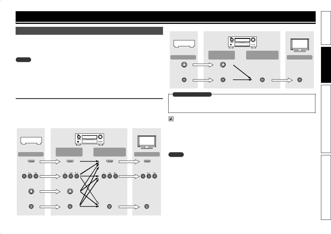
Converting input video signals for output (Video conversion function)
This unit is equipped with four types of video input connectors (HDMI, Component video, S-Video and video) and three types of video output connectors (HDMI, Component video and video).
Use the connectors corresponding to the components to be connected.
This function automatically converts various formats of video signals input to this unit into the formats used to output the video signals from this unit to a monitor.
GFlow of video signals for MAIN ZONEH
Video device |
|
This unit |
|
|
|
|
Input |
Output |
Output |
(IN) |
(MONITOR OUT) |
HDMI connector |
HDMI connector |
HDMI |
|
|
connector |
Component video |
Component video |
Component video |
connectors |
connectors |
connectors |
S-Video connector |
S-Video connector |
|
Video connector |
Video connector |
Video connector |
Monitor |
Input
HDMI connector
Component video connectors
Video connector
 : when 480i/576i signals are input
GFlow of video signals for ZONE2H
Video device |
|
This unit |
|
|
|
|
Input |
Output |
Output |
(IN) |
(MONITOR OUT) |
S-Video connector |
S-Video connector |
|
Video connector |
Video connector |
Video connector |
Monitor |
Input
Video connector
in Set as Necessary
•Set when not using the video conversion function.
“Video Convert” (vpage 83)
•Set when changing the resolution of the video signal.
“Resolution” (vpage 84)
•The video conversion function supports the NTSC, PAL, SECAM, NTSC 4.43, PAL-N, PAL-M and PAL-60 formats.
•The resolution of the video signal input to this unit’s HDMI connector is the one set at “Resolution” (vpage 84). (1080p HDMI signals and 1080p component signals are output at 1080p, regardless of the setting.)
•Resolutions of HDMI-compatible TVs can be checked at “HDMI Information” – “Monitor 1” or “Monitor 2” (vpage 107).
NOTE
•HDMI signals cannot be converted into analog signals.
•When a non-standard video signal from a game machine or some other source is input, the video conversion function might not operate.
•480p/576p/1080i/720p/1080p component video input signals cannot be converted into Video format.
15
version Simple
version Basic
version Advanced
Information
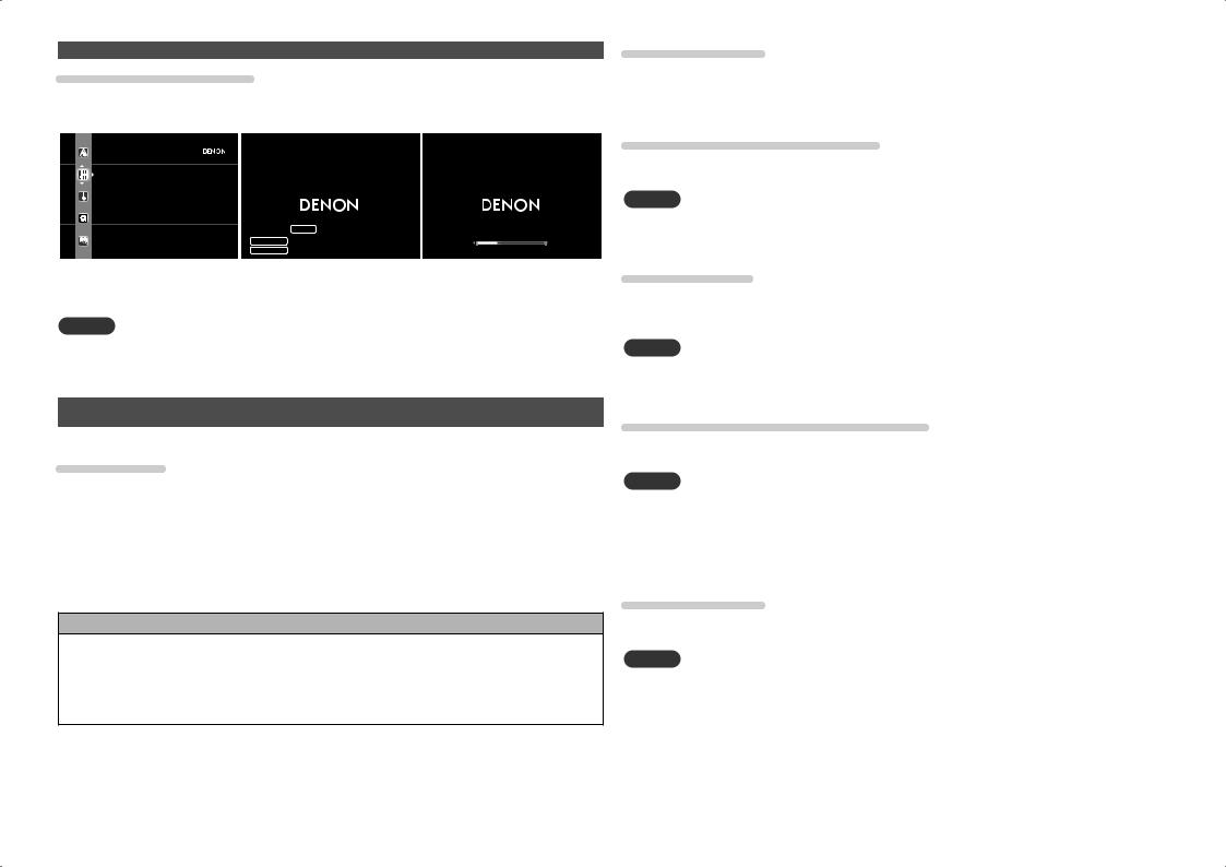
Examples of screen display
• Menu screen
 AUDIO/VIDEO ADJUST
Audio Adjust
Picture Adjust
Adjust various audio and video parameters
•Status display screen When the input source is switched
AUTO
SOURCE BD
SURROUND STEREO
Important information
When the volume is adjusted
-52.0dB
Status display: The operating status appears briefly on the screen when the input source is switched or the volume is changed.
NOTE
•If you operate the menu while playing back 3D video content, the playback video is replaced by the menu screen. The playback video is not displayed behind the menu screen.
•This unit does not show the status display while playing back 3D video content.
Connecting an HDMI-compatible device
You can connect up to seven HDMI-compatible devices to the unit.
HDMI function
This unit supports the following HDMI functions:
•3D
•Deep Color (vpage 132)
•Auto Lip Sync (vpage 98, 132)
•x.v.Color, sYCC601 color, Adobe RGB color, Adobe YCC601 color (vpage 132, 134)
•High definition digital audio format
•ARC (Audio Return Channel)
•Content Type
•CEC (HDMI control)
Copyright protection system
In order to play back digital video and audio such as BD-Video or DVD-Video via HDMI connection, both this unit and TV or the player need to support the copyright protection system known as HDCP (Highbandwidth Digital Content Protection System). HDCP is copyright protection technology comprised of data encryption and authentication of the connected AV device. This unit supports HDCP.
•If a device that does not support HDCP is connected, video and audio are not output correctly. Read the owner’s manual of your television or player for more information.
About HDMI cables
•When a device supporting Deep Color signal transfer is connected, use a cable compatible “High Speed HDMI cable” or “High Speed HDMI cable with Ethernet”.
•When the ARC function is used, connect a device with a ”Standard HDMI cable with Ethernet” or “High Speed HDMI cable with Ethernet” for HDMI 1.4a.
HDMI control function (vpage 65)
This function allows you to operate external devices from the receiver and operate the receiver from external devices.
NOTE
•The HDMI control function may not work depending on the device it is connected to and its settings.
•You cannot operate a TV or Blu-ray Disc player/DVD player that is not compatible with the HDMI control function.
About 3D function
This unit supports input and output of 3D (3 dimensional) video signals of the HDMI 1.4a standards.
To play back 3D video, you need a TV and player that provide support for HDMI1.4a standard 3D function and a pair of 3D glasses.
NOTE
•If you operate the menu while playing back 3D video content, the playback video is replaced by the menu screen. The playback video is not displayed behind the menu screen.
•This unit does not show the status display while playing back 3D video content.
About ARC (Audio Return Channel) function
The Audio Return Channel in HDMI 1.4a enables a TV, via a single HDMI cable, to send audio data “upstream” to this unit.
NOTE
•To enable the ARC function, set “HDMI Control” – “Control” to “ON” (vpage 99).
•The ARC function cannot use the HDMI MONITOR 1 and HDMI MONITOR 2 terminals simultaneously. Perform the “HDMI Control” – “Control Monitor” setting in accordance with a TV that supports the ARC function and HDMI MONITOR terminal in this unit.
•When connecting a TV that does not support the ARC function, a separate connection using an audio cable is required. In this case, refer to “Connecting a TV” (vpage 18) for the connection method.
About Content Type
The HDMI specification version 1.4a enables simple, automated picture setting selection with no user intervention.
NOTE
To enable the Content Type, set “Video Mode” to “Auto” (vpage 83).
16
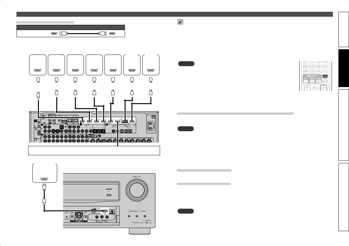
Connecting an HDMI-compatible device
Cables used for connections
Audio and video cable (sold separately)
HDMI cable
• This interface allows transfer of digital video signals and digital audio signals over a single HDMI cable.
Blu-ray |
|
|
|
|
|
|
|
|
|
Digital |
|
|
|
|
|
|
|
|
|
|
|
|
||||||
Disc |
|
DVD |
|
Set-top |
|
video |
|
Game |
|
|
|
|
|
|
|
|
||||||||||||
|
TV 1 |
|
TV 2 |
|||||||||||||||||||||||||
player |
|
player |
|
box |
|
recorder |
|
console |
|
|
||||||||||||||||||
|
|
|
|
|
|
|
|
|||||||||||||||||||||
HDMI |
|
HDMI |
|
HDMI |
|
HDMI |
|
HDMI |
HDMI |
|
HDMI |
|||||||||||||||||
OUT |
|
OUT |
|
OUT |
|
OUT |
|
OUT |
|
IN |
|
|
IN |
|||||||||||||||
|
|
|
|
|
|
|
|
|
|
|
|
|
|
|
|
|
|
|
|
|
|
|
|
|
|
|
|
|
|
|
|
|
|
|
|
|
|
|
|
|
|
|
|
|
|
|
|
|
|
|
|
|
|
|
|
|
|
|
|
|
|
|
|
|
|
|
|
|
|
|
|
|
|
|
|
|
|
|
|
|
|
|
|
|
|
|
|
|
|
|
|
|
|
|
|
|
|
|
|
|
|
|
|
|
|
|
|
|
|
|
|
|
|
|
|
|
|
|
|
|
|
|
|
|
|
|
|
|
|
|
|
|
|
|
|
|
|
|
|
|
|
|
|
|
|
|
|
|
|
|
|
|
|
|
|
|
|
|
|
|
|
|
|
|
|
|
|
|
|
|
|
|
|
|
|
|
|
|
|
|
|
|
|
|
|
|
|
|
|
|
|
|
|
|
|
|
|
|
|
|
|
|
|
|
|
|
|
|
|
|
|
|
|
|
|
|
|
|
|
|
|
|
|
|
|
|
|
|
|
|
|
GRear panelH |
When a control dock for iPod is not used, you can connect other HDMI-compatible devices.
Digital camcorder
GFront panelH
HDMI
OUT
•When this unit is connected to other devices with HDMI cables, connect this unit and TV also with an HDMI cable.
•When connecting a device that supports Deep Color transmission, please use a “High Speed HDMI cable” or “High Speed HDMI cable with Ethernet”.
•Video signals are not output if the input video signals do not match the monitor’s resolution. In this case, switch the Blu-ray Disc/DVD player’s resolution to a resolution with which the monitor is compatible.
•When this unit and monitor are connected with an HDMI cable, if the monitor is not compatible with
HDMI audio signal playback, only the video signals are output to the monitor.
NOTE
• When the “Monitor Out” menu is set to “Auto (Dual)”, video may not
displayed properly on some monitors connected to the unit. In such a case,
to either “Monitor 1” or “Monitor 2” by pressing the MONITOR SELECT button on the remote control unit.
• When you use the HDMI control function, set “HDMI Control” – “Control” “ON” and set the HDMI MONITOR terminal that you want to operate by HDMI control function in “Control Monitor”.
•The audio signal from the HDMI output connector (sampling frequency, number of channels, etc.) may be limited by the HDMI audio specifications of the connected device regarding permissible inputs.
Connecting to a device equipped with a DVI-D connector
When an HDMI/DVI conversion cable (sold separately) is used, the HDMI video signals are converted to DVI signals, allowing connection to a device equipped with a DVI-D connector.
NOTE
•No sound is output when connected to a device equipped with a DVI-D connector. Make separate audio connections.
•Signals cannot be output to DVI-D devices that do not support HDCP.
•Depending on the combination of devices, the video signals may not be output.
nnSettings related to HDMI connections
Set as necessary. For details, see the respective reference pages.
Input Assign (vpage 82)
Set this to change the HDMI input connector to which the input source is assigned.
HDMI Setup (vpage 98)
Make settings for HDMI video/audio output.
• RGB Range |
• HDMI Audio Out |
• Vertical Stretch |
• Monitor Out |
• Auto Lip Sync |
• HDMI Control |
NOTE
The audio signals output from the HDMI connectors are only the HDMI input signals.
17
version Simple
version Basic
version Advanced
Information
Connecting a TV
•Select the connector to use and connect the device.
•For video connections, see “Converting input video signals for output (Video conversion function)” (vpage 15).
•For instructions on HDMI connections, see “Connecting an HDMI-compatible device” (vpage 16).
To listen to TV audio through this device, use the optical digital connection.
NOTE
The optical connection is not required when a TV compatible with the ARC function (Audio Return Channel (HDMI 1.4a standard function) is connected to this unit via an HDMI connection.
For details, see “About ARC (Audio Return Channel) function” (vpage 16) or refer to the instruction manual for your TV.
Cables used for connections |
||||
|
|
|
Video cable (sold separately) |
|
Video cable |
|
|
(Yellow) |
|
Component video |
|
(Green) |
||
|
(Blue) |
|||
cable |
|
|
|
|
|
|
|
(Red) |
|
|
|
|
|
|
|
|
|
Audio cable (sold separately) |
|
Optical cable |
|
|
|
|
TV |
|
|
|
|
|
|
VIDEO |
|
AUDIO |
COMPONENT VIDEO |
VIDEO |
OPTICAL |
||
|
IN |
|
IN |
OUT |
Y |
PB |
PR |
|
|
Connecting a Blu-ray Disc player
•You can enjoy video and audio from a Blu-ray Disc.
•Select the connector to use and connect the device.
•For instructions on HDMI connections, see “Connecting an HDMI-compatible device” (vpage 16).
Cables used for connections
Video cable (sold separately)
Video cable (Yellow) 


Audio cables (sold separately)
Audio cable |
(White) |
L |
L |
|
(Red) |
R |
R |
||
|
||||
Blu-ray Disc player |
|
|
||
VIDEO |
AUDIO |
|
|
|
VIDEO |
AUDIO |
|
|
|
OUT |
OUT |
|
|
|
LR
L |
R |
L 
 R
R
in Set as Necessary
Set this to change the digital input connector or component video input connector to which the input source is assigned.
“Input Assign” (vpage 82)
For HD audio (Dolby TrueHD, DTS-HD, Dolby Digital Plus and DTS Express) playback, connect with HDMI (vpage 16 “Connecting an HDMI-compatible device”).
in Set as Necessary
Set this to change the digital input connector or component video input connector to which the input source is assigned.
“Input Assign” (vpage 82)
18
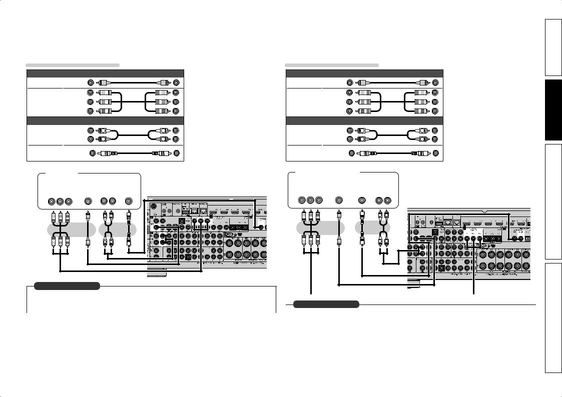
Connecting a DVD player |
|
Connecting a set-top box (Satellite tuner/cable TV) |
• You can enjoy video and audio from a DVD. |
• You can watch satellite or cable TV. |
|
• Select the connector to use and connect the device. |
• Select the connector to use and connect the device. |
|
• For instructions on HDMI connections, see “Connecting an HDMI-compatible device” (vpage 16). |
• For instructions on HDMI connections, see “Connecting an HDMI-compatible device” (vpage 16). |
|
Cables used for connections
|
Video cable (sold separately) |
|
||
Video cable |
(Yellow) |
|
|
|
Component |
(Green) |
|
|
|
(Blue) |
|
|
||
video cable |
|
|
||
(Red) |
|
|
||
|
|
|
||
|
Audio cables (sold separately) |
|
||
Audio cable |
(White) |
L |
L |
|
(Red) |
R |
R |
||
|
||||
Coaxial |
(Orange) |
|
|
|
digital cable |
|
|
||
|
|
|
||
DVD player
|
VIDEO |
|
|
|
|
AUDIO |
|
||
|
|
|
|
|
|||||
|
|
|
|
|
|
|
|
|
|
|
|
|
|
|
|
|
|
|
|
|
|
|
|
|
|
|
|||
COMPONENT VIDEO |
|
VIDEO |
|
AUDIO |
|
COAXIAL |
|||
OUT |
|
OUT |
|
OUT |
|
|
OUT |
||
Y PB PR |
|
|
|
L R |
|
|
|
||
|
|
|
|
|
|
|
|
|
|
Cables used for connections
|
Video cable (sold separately) |
|
||
Video cable |
(Yellow) |
|
|
|
Component |
(Green) |
|
|
|
(Blue) |
|
|
||
video cable |
|
|
||
(Red) |
|
|
||
|
|
|
||
|
Audio cables (sold separately) |
|
||
Audio cable |
(White) |
L |
L |
|
(Red) |
R |
R |
||
|
||||
Coaxial |
(Orange) |
|
|
|
digital cable |
|
|
||
|
|
|
||
Satellite tuner/Cable TV
|
VIDEO |
|
|
|
|
AUDIO |
|
||
|
|
|
|
|
|||||
|
|
|
|
|
|
|
|
|
|
|
|
|
|
|
|
|
|
|
|
COMPONENT VIDEO |
|
VIDEO |
|
COAXIAL |
|
AUDIO |
|||
OUT |
|
OUT |
|
OUT |
|
OUT |
|||
Y PB PR |
|
|
|
|
|
|
L R |
||
|
|
|
|
|
|
|
|
|
|
L |
R |
L |
R |
L |
R |
L |
R |
in Set as Necessary |
|
|
|
Set this to change the digital input connector or component video input connector to which the input |
|
|
|
|
|
|
|
|
|
|
|
source is assigned. |
|
in Set as Necessary |
|
||
“Input Assign” (vpage 82) |
|
|
|||
|
Set this to change the digital input connector or component video input connector to which the input |
|
|||
|
|
|
|||
|
|||||
|
|
source is assigned. |
|
||
|
|
“Input Assign” (vpage 82) |
|
||
|
|
|
|
|
|
19
version Simple
version Basic
version Advanced
Information
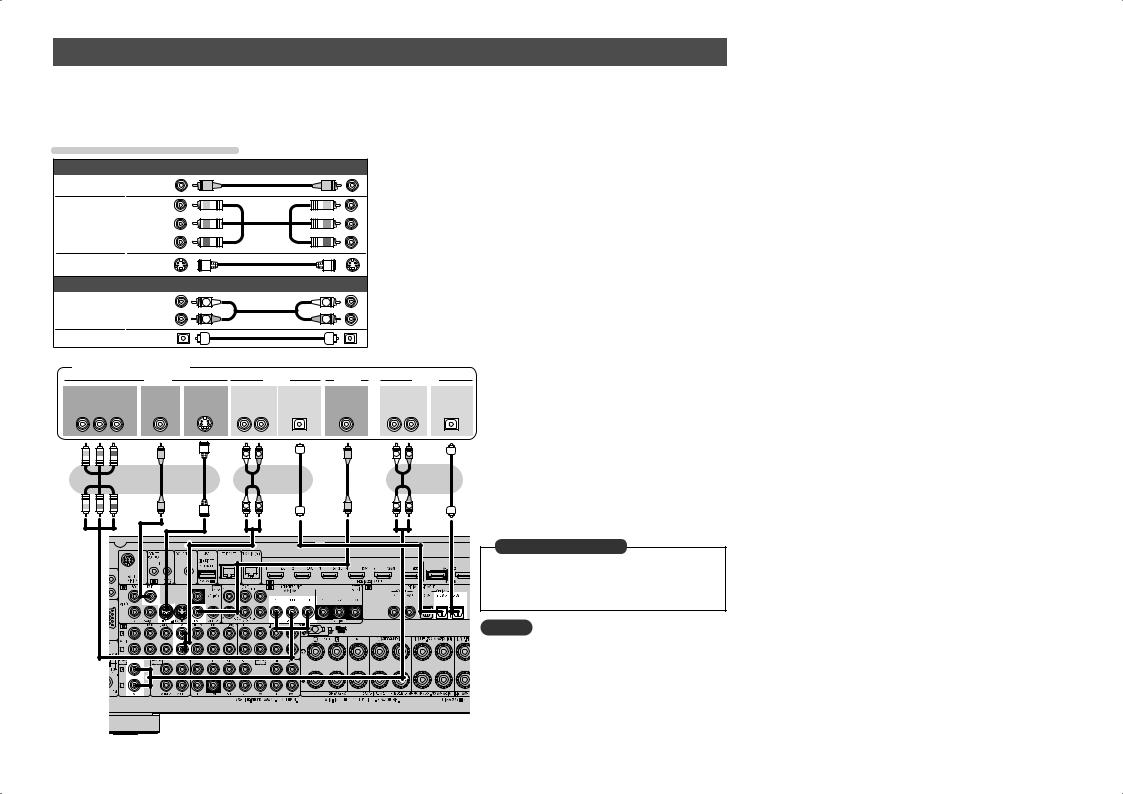
Connecting a digital video recorder
•You can record video onto a Blu-ray Disc or DVD.
•Select the connector to use and connect the device.
•When recording analog audio, use the analog connection.
•See “REC OUT mode” (vpage 67) for operating instructions.
•For instructions on HDMI connections, see “Connecting an HDMI-compatible device” (vpage 16).
Cables used for connections
|
Video cable (sold separately) |
|
||
Video cable |
(Yellow) |
|
|
|
Component |
(Green) |
|
|
|
(Blue) |
|
|
||
video cable |
|
|
||
(Red) |
|
|
||
|
|
|
||
S-Video cable |
|
|
|
|
|
Audio cable (sold separately) |
|
||
Audio cable |
(White) |
L |
L |
|
(Red) |
R |
R |
||
|
||||
Optical cable |
|
|
|
|
Digital video recorder
|
VIDEO |
|
|
|
AUDIO |
VIDEO |
|
|
AUDIO |
COMPONENT VIDEO |
VIDEO |
S-VIDEO |
AUDIO |
OPTICAL |
VIDEO |
AUDIO |
OPTICAL |
||
OUT |
OUT |
OUT |
OUT |
OUT |
IN |
IN |
|
IN |
|
Y PB PR |
|
|
L |
R |
|
|
L |
R |
|
|
|
|
L |
R |
|
|
L |
R |
|
L |
R |
L |
R |
|
|
|
in Set as Necessary |
|
|
|
Set this to change the digital input connector or |
|
|
|
component video input connector to which the |
|
|
|
input source is assigned. |
|
|
|
“Input Assign” (vpage 82) |
|
|
|
NOTE |
|
|
|
To record video signals through this unit, use the |
|
|
|
video cable for connection between this unit and the |
|
|
|
player. |
20

Connecting a digital camcorder
•You can enjoy video and audio from a digital camcorder.
•You can enjoy games by connecting a game machine via the V.AUX input connector. In this case, select the input source to “V.AUX”.
•For instructions on HDMI connections, see “Connecting an HDMI-compatible device” (vpage 16).
Cables used for connections
Video cable (sold separately)
Video cable (Yellow) 


Audio cable (sold separately)
Audio cable |
(White) |
L |
L |
|
(Red) |
R |
R |
||
|
||||
Digital camcorder |
|
|
||
VIDEO |
AUDIO |
|
|
|
VIDEO |
AUDIO |
|
|
|
OUT |
OUT |
|
|
|
LR
L 
 R
R
L |
R |
in Set as Necessary
Set this to change the digital input connector or component video input connector to which the input source is assigned.
“Input Assign” (vpage 82)
NOTE
When a non-standard video signal from a game machine or some other source is input, the video conversion function might not operate. In this case, use the monitor output of the same connector as the input.
Connecting a control dock for iPod
•Connect a control dock for iPod to the unit to enjoy video and music stored on an iPod.
•For a control dock for iPod, use ASD-1R and ASD-11R made by DENON (sold separately).
•For instructions on the control dock for iPod settings, refer to the control dock for iPod’s operating instructions.
Control dock for iPod
Use the AV/Control Cable supplied with the DENON control dock for iPod.
|
ASD-11R |
R |
L |
R |
L |
You can also connect the iPod you are using directly to the USB port of this unit (vpage 22 “Connecting an iPod or USB memory device to the USB port”).
NOTE
When connecting an iPhone to this unit, keep the iPhone at least 20 cm away from this unit. If the iPhone is kept closer to this unit and a telephone call is received by the iPhone, noise may be output from this device.
21
version Simple
version Basic
version Advanced
Information
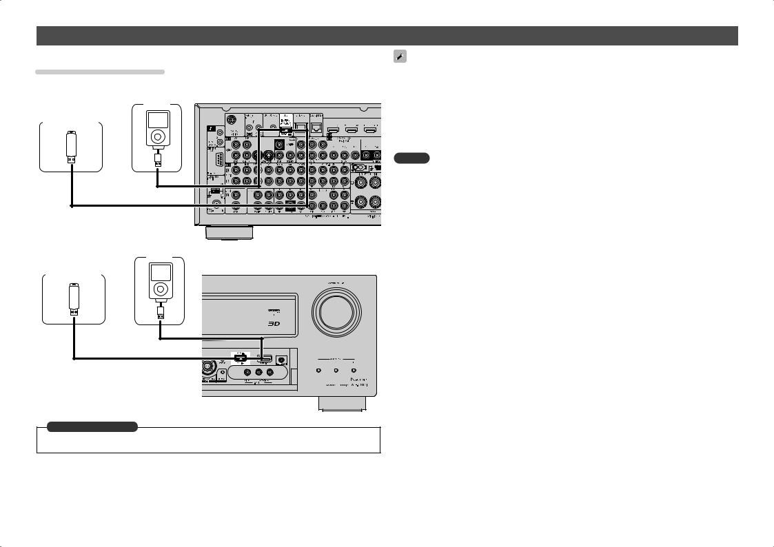
Connecting an iPod or USB memory device to the USB port
You can enjoy music stored on an iPod or USB memory device.
Cables used for connections
To connect an iPod to this unit, use the USB cable supplied with the iPod.
GRear panelH
iPod |
USB memory |
device |
or |
•In the initial status, USB memory devices can be used by connecting them to the USB port on the front panel.
•When you want to playback a video file stored on an iPod, use a DENON control dock for iPod (ASD-1R and ASD-11R, sold separately) (vpage 21 “Connecting a control dock for iPod”).
•With iPods, playback is possible with iPhone, iPod touch, classic and nano released from the 5th-generation of iPods. For details, check the DENON web site or page 32.
•DENON does not guarantee that all USB memory devices will operate or receive power. When using a portable USB connection type HDD of the kind to which an AC adapter can be connected to supply power, use the AC adapter.
NOTE
•You cannot use the USB ports on the front panel and rear panel simultaneously. Select and connect the USB port to use.
•USB memory devices will not work via a USB hub.
•Do not use an extension cable when connecting a USB memory device. This may cause radio interference with other devices.
•This unit does not support playback on an iPad. Do not connect an iPad to the unit.
iPod
USB memory |
GFront panelH |
|
device |
||
|
||
|
or |
in Set as Necessary
Set when you change the USB port to use.
“USB Select” (vpage 85)
22
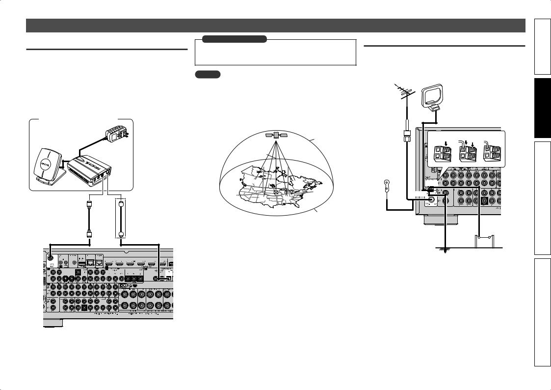
Connecting an antenna
Connecting a SIRIUS connector
•This unit is a SIRIUS Satellite Radio Ready® receiver. You can receive SIRIUS® Satellite Radio by connecting to the SiriusConnect Home Tuner and subscribing to the SIRIUS service.
•Plug the SIRIUS connector on the SIRIUS service.
•Position the Home Tuner antenna near a south-facing window to receive the best signal.
For details, see “Listening to SIRIUS satellite radio” (vpage 33). When making connections, also refer to the operating instructions of the SiriusConnect Home Tuner.
SiriusConnect Home Tuner
When connecting digital audio
in Set as Necessary
When connecting digital of the SiriusConnect Home Tuner, perform the setting “Digital”.
“Input Assign” (vpage 82)
NOTE
Keep the power cord unplugged until the SiriusConnect Home Tuner connection have been completed.
nnPositioning the antenna
For a consistent satellite signal, the antenna must be positioned correctly. Use the following map to determine which area you are in and position the antenna accordingly.
|
|
|
|
SKY |
|
NORTH |
|
|
|
WEST |
q |
t |
r |
EAST |
|
|
|
||
|
w |
|
e |
|
HORIZON
SOUTH
Area 1 Point the antenna toward the sky in the east, northeast, or southeast, either through a window or outside.
Area 2 Point the antenna toward the sky in the north or northeast, either through a window or outside.
Area 3 Point the antenna toward the sky in the north or northwest, either through a window or outside.
Area 4 Point the antenna toward the sky in the west, northwest, or southwest, either through a window or outside.
Area 5 Put the antenna outside and point it straight up. The antenna cannot be used indoors.
Connecting an HD Radio receiver
•By connecting a HD Radio antenna to this unit, you can receive HD Radio programs.
•HD Radio broadcasting currentry is available in the United States and select other countries.
Direction of broadcasting station |
AM loop antenna |
||
|
|
||
|
|
(for HD Radio broadcasting, |
|
FM outdoor |
|
supplied) |
|
|
• To prevent interference, install |
||
antenna |
|
||
|
at least 3.3 ft/1 m away from the |
||
|
|
||
|
|
antenna connected to the this |
|
|
|
unit’s other AM tuner terminal. |
|
75 Ω coaxial |
q |
w |
e |
cable |
|||
FM indoor |
|
|
|
antenna (for |
|
|
|
HD Radio |
|
|
|
broadcasting, |
|
|
|
supplied) |
|
|
|
White |
Black |
AM outdoor
Ground antenna
23
version Simple
version Basic
version Advanced
Information
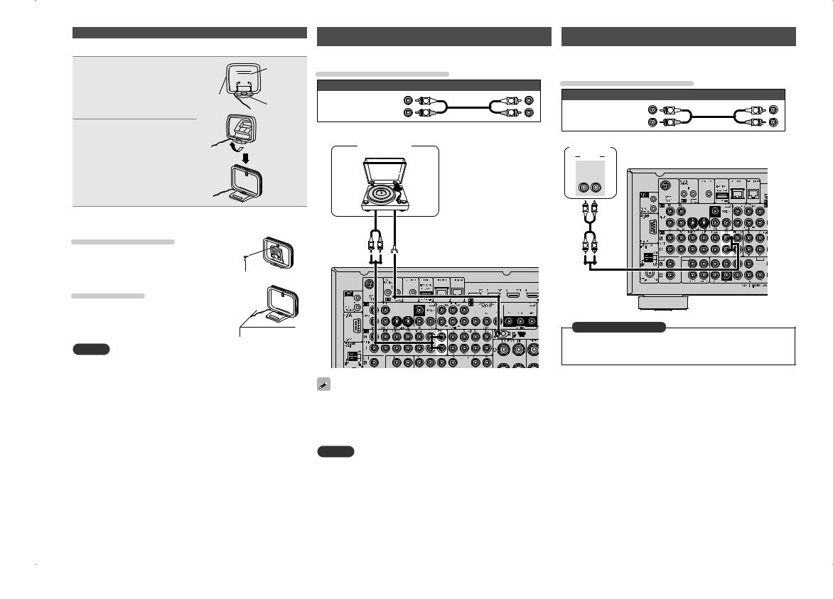
Connecting an antenna
nnAM loop antenna assembly
1 Put the stand section through the bottom of the loop antenna from the rear and bend it forward.
2 Insert the projecting part into the square hole in the stand.
Stand


 Square
hole
Loop |
Projecting |
|
antenna |
||
part |
||
|
Connecting a record player |
|
Connecting a CD player |
|
|||||
You can enjoy playing records. |
|
|
• You can enjoy CD sound. |
|
|
|||
Cables used for connections |
|
• Select the connector to use and connect the device. |
|
|||||
|
Cables used for connections |
|
||||||
|
Audio cable (sold separately) |
|
|
|||||
|
|
|
|
|
|
|
||
|
(White) |
L |
L |
|
|
Audio cable (sold separately) |
|
|
Audio cable |
|
|
|
|
|
|||
(Red) |
R |
R |
|
|
(White) |
L |
L |
|
|
Audio cable |
|||||||
|
|
|
|
|
||||
|
|
|
|
(Red) |
R |
R |
||
|
|
|
|
|
|
|||
|
Turntable |
|
|
|
|
|
|
|
(MM cartridge) |
|
|
CD player |
|
|
|
||
|
|
|
|
AUDIO |
|
|
|
|
|
|
|
|
AUDIO |
|
|
|
|
|
|
|
|
OUT |
|
|
|
|
|
|
|
|
L |
R |
|
|
|
nnUsing the AM loop antenna
Suspending on a wall
Suspend directly on a wall without assembling.
Nail, tack, etc.
Standing alone
Use the procedure shown above to assemble.
NOTE
•Do not connect two FM antennas simultaneously.
•Even if an external AM antenna is used, do not disconnect the AM loop antenna.
•Make sure the AM loop antenna lead terminals do not touch metal parts of the panel.
•If the signal has noise interference, connect the ground terminal (GND) to reduce noise.
•If you are unable to receive a good broadcast signal, we recommend installing an outdoor antenna. For details, inquire at the retail store where you purchased the unit.
|
|
L |
R |
AUDIO |
|
GND |
|
OUT |
|
|
|
|
|
|
|
L |
R |
L |
R |
|
|
in Set as Necessary |
|
|
|
Set this to change the digital input connector to which the input |
|
|
|
source is assigned. |
|
|
|
“Input Assign” (vpage 82) |
|
•This unit is compatible with record players with an MM cartridge. When you connect to a record player with an MC cartridge, use a commercially available MC head amp or a step-up transformer.
•When you increase the volume without connecting the record player, there may be “booming” noise from the speakers.
NOTE
The SIGNAL GND terminal of this unit is not a safety ground connection. Connect it to reduce noise when noise is excessive. Note that depending on the record player, connecting the ground line may have the reverse effect of increasing noise. In this case, it is not necessary to connect the ground line.
24

Component equipped with a DENON LINK connector
Multichannel playback is possible. That includes DVD-Audio and Super Audio CD (vpage 30 “Playing an iPod®”).
Also, refer to page 29 “Playing a Blu-ray Disc player compatible with DENON LINK 4th” for information on connecting a player that supports DENON LINK 4th edition.
Cables used for connections
Audio cable (sold separately)
DENON LINK cable
Blu-ray Disc player /
DVD player
AUDIO
DENON LINK
in Set as Necessary
When connecting by use of DENON LINK, set “Digital” to “D.LINK”.
“Input Assign” (vpage 82)
Component with Multi-channel Output connectors
•You can connect this unit to an external device fitted with multichannel sound audio output jacks to enjoy music and video.
•The video signal can be connected in the same way as a Blu-ray Disc player / DVD player (vpage 18 “Connecting a Blu-ray Disc player”).
Cables used for connections
|
Audio cable (sold separately) |
|
||
Audio cable |
(White) |
L |
L |
|
(Red) |
R |
R |
||
|
||||
Audio cable |
|
|
|
|
Blu-ray Disc player / DVD player
|
|
|
AUDIO |
|
|
|
SUB- |
FRONT |
CENTER SURROUND |
SURROUND |
|||
WOOFER |
|
|
|
|
BACK |
|
|
L |
R |
L |
R |
L |
R |
|
L |
R |
L |
R |
L |
R |
L |
R |
L |
R |
L |
R |
in Set as Necessary
To play analog signals input from the external input (EXT. IN) terminal, set “Input Mode” (vpage 84) to “EXT. IN”.
Connecting a external power |
|
Simple |
amplifier |
|
|
|
|
|
• You can use this unit as a pre-amp by connecting a commercially |
version |
|
to each of the channels provides an even greater sound presence. |
||
available power amp to the PRE OUT connector. Adding a power amp |
|
|
• Select the terminal to use and connect the device. |
|
|
Cables used for connections
|
Audio cable (sold separately) |
Basic |
|||
Audio cable |
(White) |
L |
L |
||
|
|
|
|||
(Red) |
R |
R |
version |
||
|
|||||
Audio cable |
|
|
|
||
|
|
|
|
||
Subwoofer |
Power amplifier |
|
|
||
AUDIO |
|
|
AUDIO |
|
|
SUB- |
SUB- |
|
FRONT |
CENTER SURROUND SURROUND |
FRONT |
FRONT |
|
WOOFER WOOFER |
|
|
|
BACK |
HEIGHT |
WIDE |
|
2 |
1 |
|
L R |
L R |
L R |
L R |
L R |
|
|
|
|||||
|
|
|
|
|
|
|
|
L |
R |
L |
R |
L |
R |
L |
R |
L |
R |
Advanced |
L |
R |
L |
R |
L |
R |
L |
R |
L |
R |
version |
• When using just one surround back speaker, connect it to the left |
|
|
channel (L) terminal. |
|
|
• Use the volume control on the subwoofer to control subwoofer |
Information |
|
volume. |
||
|
||
• If the subwoofer volume sounds low, use the volume control |
|
|
provided on the subwoofer to adjust the volume. |
|
|
• You can use this unit as a preamplifier. For details, see “PRE AMP |
|
|
mode” (vpage 62). |
|
NOTE
When external power amplifier have been connected to PRE OUT terminals, do not connect the speakers to the speaker terminals.
25
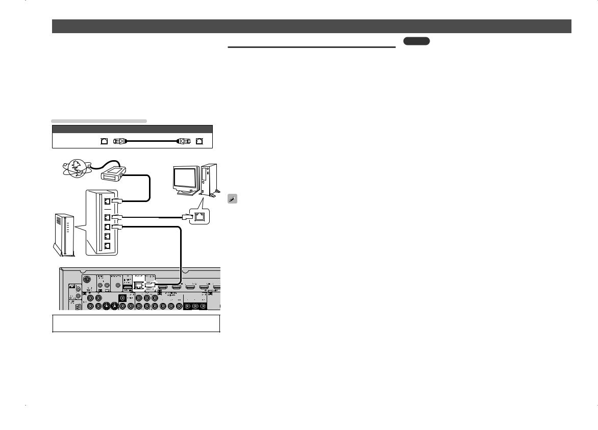
Connecting to a home network (LAN)
•This unit lets you play via your home network (LAN) music files stored on a computer and music content such as that from Internet radio.
You can also operate this unit from a computer using the Web control function.
•You can update by downloading the latest firmware from the DENON website.
For more information, on the menu, select “Firmware Update” (vpage 106).
•See“NetworkSetup”onthemenu(vpage101)formoreinformation on network setting.
Cables used for connections
Cable (sold separately)
Ethernet cable
Computer
Modem
Internet
Required system
nnBroadband internet connection
nnModem
Device that connects to the broadband circuit and conducts communications on the Internet.
A type that is integrated with a router is also available.
nnRouter
When using this unit, we recommend you use a router equipped with the following functions:
•Built-in DHCP server
This function automatically assigns IP addresses on the LAN.
•Built-in 100BASE-TX switch
When connecting multiple devices, we recommend a switching hub with a speed of 100 Mbps or greater.
nnEthernet cable (CAT-5 or greater recommended)
•Use only shielded STP or ScTP LAN cable which is available at retailer.
•Some flat type Ethernet cables are easily affected by noise. We recommend using a normal type cable.
To WAN side |
|
|
To LAN port |
|
|
To LAN port |
LAN port/ |
|
Ethernet |
||
|
||
|
connector |
Router |
•If you have an Internet provider contract for a line on which network settings are made manually, make the settings at “Network Setup” (vpage 101).
•With this unit, it is possible to use the DHCP and Auto IP functions to make the network settings automatically.
•When using this unit with the broadband router’s DHCP function enabled, this unit automatically performs the IP address setting and other settings.
When using this unit connected to a network with no DHCP function, make the settings for the IP address, etc., at “Network Setup” (vpage 101).
•When setting manually, check the setting contents with the network administrator.
NOTE
•A contract with an ISP is required to connect to the Internet.
No additional contract is needed if you already have a broadband connection to the Internet.
•The types of routers that can be used depend on the ISP. Contact an ISP or a computer shop for details.
•DENON assumes no responsibility whatsoever for any communication errors or troubles resulting from customer’s network environment or connected devices.
•This unit is not compatible with PPPoE. A PPPoE-compatible router is required if you have a contract for a type of line set by PPPoE.
•Do not connect an ETHERNET connector directly to the LAN port/ Ethernet connector on your computer.
For connections to the Internet, contact an ISP (Internet Service Provider) or a computer shop.
26
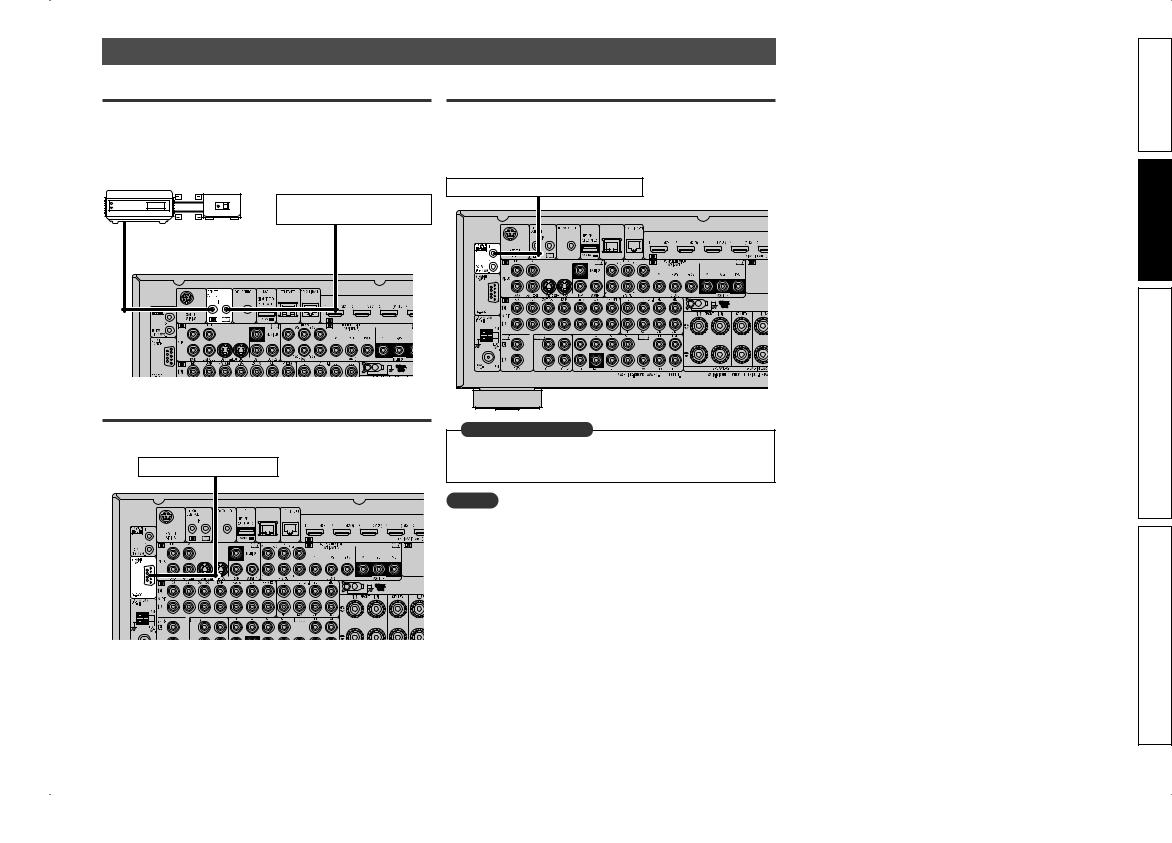
Connecting an external control device
REMOTE CONTROL jacks
If this unit is installed in a location that is out of range of the signal from the remote control unit, you can still operate the unit and the devices connected to it by using a commercially available IR receiver. You can also use it to remotely control ZONE2, ZONE3 (another room).
Infrared Infrared retransmitter sensor
AUX |
Input |
Output |
|
||
OUT |
|
|
Device equipped with a REMOTE CONTROL IN jack
RS-232C connector
When you connect an external control device, you can control this unit with the external control device.
External serial controller
Perform the operation below beforehand. q Turn on the power of this unit.
w Turn off the power of this unit from the external controller. e Check that the unit is in the standby mode.
TRIGGER OUT jacks
When a device with TRIGGER IN jack is connected, the connected device’s power on/standby can be controlled through linked operation to this unit.
The TRIGGER OUT jack outputs a maximum 12 V/150 mA electrical signal. 
12 V/150 mA trigger-compatible device
in Set as Necessary
Set to change the conditions for linked operation via the TRIGGER OUT 1 or 2 jack.
“Trigger Out 1” or “Trigger Out 2” (vpage 105)
NOTE
•Use the monaural mini-plug cable for connecting TRIGGER OUT jacks. Do not use the stereo mini-plug cable.
•If the permissible trigger input level for the connected device is larger than 12V/150mA, or has shorted, the TRIGGER OUT jack cannot be used. In this case, turn off the power to the unit, and disconnect it.
version Simple
version Basic
version Advanced
Information
27
 Loading...