


AVR-3313CI
INTEGRATED NETWORK AV RECEIVER
Owner’s Manual
version Basic
version Advanced
Informations
nSAFETY PRECAUTIONS
CAUTION
RISK OF ELECTRIC SHOCK
DO NOT OPEN
CAUTION:
TO REDUCE THE RISK OF ELECTRIC SHOCK, DO NOT REMOVE COVER (OR BACK). NO USER-SERVICEABLE PARTS INSIDE. REFER SERVICING TO QUALIFIED SERVICE PERSONNEL.
The lightning flash with arrowhead symbol, within an equilateral triangle, is intended to alert the user to the presence of uninsulated “dangerous voltage” within the product’s enclosure that may be of sufficient magnitude to constitute a risk of electric shock to persons.
The exclamation point within an equilateral triangle is intended to alert the user to the presence of important operating and maintenance (servicing) instructions in the literature
accompanying the appliance.
WARNING:
TO REDUCE THE RISK OF FIRE OR ELECTRIC SHOCK, DO NOT EXPOSE THIS APPLIANCE TO RAIN OR MOISTURE.
|
|
|
CAUTION: |
|
|
|
HOT SURFACE. DO NOT TOUCH. |
|
|
|
The top surface over the internal heat sink may become hot |
|
|
|
|
|
Hot |
when operating this product continuously. |
|
surface |
Do not touch hot areas, especially around the “Hot surface |
||
mark |
mark” and the top panel. |
||
|
|||
IMPORTANT SAFETY
INSTRUCTIONS
1.Read these instructions.
2.Keep these instructions.
3.Heed all warnings.
4.Follow all instructions.
5.Do not use this apparatus near water.
6.Clean only with dry cloth.
7.Do not block any ventilation openings.
Install in accordance with the manufacturer’s instructions.
8.Do not install near any heat sources such as radiators, heat registers, stoves, or other apparatus (including amplifiers) that produce heat.
9.Do not defeat the safety purpose of the polarized or grounding-type plug. A polarized plug has two blades with one wider than the other. A grounding type plug has two blades and a third grounding prong. The wide blade or the third prong are provided for your safety. If the provided plug does not fit into your outlet, consult an electrician for replacement of the obsolete outlet.
10.Protect the power cord from being walked on or pinched particularly at plugs, convenience receptacles, and the point where they exit from the apparatus.
11.Only use attachments/accessories specified by the manufacturer.
12.Use only with the cart, stand, tripod, bracket, or table
specified by the manufacturer, or sold with the apparatus. When a cart is used, use caution when moving the cart/ apparatus combination to avoid injury from tip-over.
13. Unplug this apparatus during lightning storms or when unused for long periods of time.
14.Refer all servicing to qualified service personnel.
Servicing is required when the apparatus has been damaged in any way, such as power-supply cord or plug is damaged, liquid has been spilled or objects have fallen into the apparatus, the apparatus has been exposed to rain or moisture, does not operate normally, or has been dropped.
15.Batteries shall not be exposed to excessive heat such as sunshine, fire or the like.
CAUTION:
To completely disconnect this product from the mains, disconnect the plug from the wall socket outlet.
The mains plug is used to completely interrupt the power supply to the unit and must be within easy access by the user.
FCC INFORMATION (For US customers)
1.COMPLIANCE INFORMATION
Product Name: Integrated Network AV Receiver Model Number: AVR-3313CI
This product complies with Part 15 of the FCC Rules. Operation is subject to the following two conditions: (1) this product may not cause harmful interference, and (2) this product must accept any interference received, including interference that may cause undesired operation.
Denon Electronics (USA), LLC (a D&M Holdings Company) 100 Corporate Drive Mahwah, NJ 07430-2041 Tel. (201) 762-6665
2.IMPORTANT NOTICE: DO NOT MODIFY THIS PRODUCT
This product, when installed as indicated in the instructions contained in this manual, meets FCC requirements. Modification not expressly approved by DENON may void your authority, granted by the FCC, to use the product.
3.IMPORTANT
When connecting this product to network hub or router, use only a shielded STP or ScTP LAN cable which is available at retailer.
Follow all installation instructions. Failure to follow instructions could void your authority, granted by the FCC, to use the product.
4.NOTE
This product has been tested and found to comply with the limits for a Class B digital device, pursuant to Part 15 of the FCC Rules. These limits are designed to provide reasonable protection against harmful interference in a residential installation.
This product generates, uses and can radiate radio frequency energy and, if not installed and used in accordance with the instructions, may cause harmful interference to radio communications. However, there is no guarantee that interference will not occur in a particular installation. If this product does cause harmful interference to radio or television reception, which can be determined by turning the product OFF and ON, the user is encouraged to try to correct the interference by one or more of the following measures:
•Reorient or relocate the receiving antenna.
•Increase the separation between the equipment and receiver.
•Connect the product into an outlet on a circuit different from that to which the receiver is connected.
•Consult the local retailer authorized to distribute this type of product or an experienced radio/TV technician for help.
For Canadian customers:
This Class B digital apparatus complies with Canadian ICES-003.
version Basic
version Advanced
Informations
I
nNOTES ON USE
WARNINGS
•Avoid high temperatures.
Allow for sufficient heat dispersion when installed in a rack.
•Handle the power cord carefully.
Hold the plug when unplugging the cord.
•Keep the unit free from moisture, water, and dust.
•Unplug the power cord when not using the unit for long periods of time.
•Do not obstruct the ventilation holes.
•Do not let foreign objects into the unit.
•Do not let insecticides, benzene, and thinner come in contact with the unit.
•Never disassemble or modify the unit in any way.
•Ventilation should not be impeded by covering the ventilation openings with items, such as newspapers, tablecloths or curtains.
•Naked flame sources such as lighted candles should not be placed on the unit.
•Observe and follow local regulations regarding battery disposal.
•Do not expose the unit to dripping or splashing fluids.
•Do not place objects filled with liquids, such as vases, on the unit.
•Do not handle the mains cord with wet hands.
•When the switch is in the OFF (STANDBY) position, the equipment is not completely switched off from MAINS.
•The equipment shall be installed near the power supply so that the power supply is easily accessible.
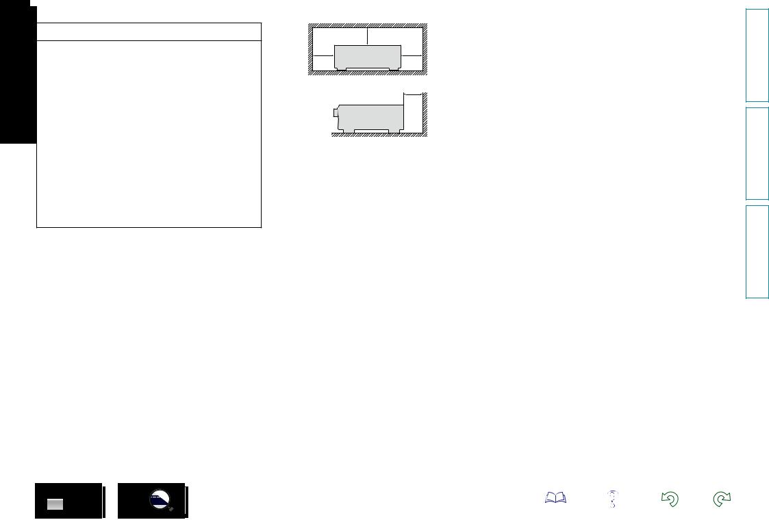
n CAUTIONS ON INSTALLATION
z
z z
z
Wall
zz For proper heat dispersal, do not install this unit in a confined space, such as a bookcase or similar enclosure.
•More than 12 in. (0.3 m) is recommended.
•Do not place any other equipment on this unit.
II
version Basic
version Advanced
Informations
Getting started
Thank you for purchasing this DENON product. To ensure proper operation, please read this owner’s manual carefully before using the product. After reading them, be sure to keep them for future reference.
Contents
Getting started···············································································1 Accessories···················································································2 Features························································································2 Cautions on handling·····································································3
Basic version············································································4
Connections···················································································5 Important information····································································5 Connecting an HDMI-compatible device·······································8 Connecting an HDMI-incompatible device··································14 Connecting a external power amplifier········································25 Connecting an external control device········································26 Connecting to a home network (LAN)·········································27 Connecting the power cord·························································28
Setup·····························································································29 Set up speakers (Audyssey® Setup)···········································29 Making the network settings (Network)······································35 Playback (Basic operation)··························································36 Important information··································································36 Playing a Blu-ray Disc player/DVD player·····································37 Playing a Blu-ray Disc player compatible with Denon Link HD····37 Playing Super Audio CD······························································38 Playing a CD player······································································38 Playing an iPod············································································39 Playing a USB memory device····················································42 Listening to HD Radio stations····················································45 Network contents········································································54 Listening to internet radio···························································54 Playing back files stored on a PC and NAS·································57 Using online services··································································61 Convenient functions··································································69 AirPlay function···········································································73
Selecting a listening mode (Sound Mode)································75 Selecting a listening mode··························································75
Advanced version································································81
Installation/connection/setup of speakers (Advanced)···········82 Speaker installation·····································································82 Speaker connection·····································································84 Set up speakers···········································································92 Playback (Advanced operation)··················································95 HDMI control function·································································95 Sleep timer function····································································97 Quick select function···································································98 REC OUT mode···········································································99 Web control function·································································100 Various memory functions························································102
Playback in ZONE2/ZONE3 (Separate room)··························103 Audio output··············································································103 Video output··············································································104 Playback····················································································105 Sleep timer function··································································105
How to make detailed settings················································106 Menu map·················································································106 Examples of menu screen displays···········································108 Examples of menu and front display·········································109 Inputting characters···································································110 Audio·························································································112 Video·························································································119 Inputs························································································124 Speakers····················································································129 Network·····················································································135 General······················································································139
Operating external devices with the remote control·············145 Registering preset codes··························································145 Operating external devices························································148 Operating devices·····································································149 Specifying the zone used with the remote control unit············151 Resetting the remote control unit·············································151
Informations·········································································152
Part names and functions·························································153 Front panel················································································153 Display·······················································································155 Rear panel·················································································156 Remote control unit···································································157
Other information······································································159 Trademark information······························································159 Surround····················································································160 Relationship between video signals and monitor output··········166 Explanation of terms·································································168
Troubleshooting········································································171 Resetting the microprocessor···················································176 Specifications·············································································177
version Basic
version Advanced
Informations
1

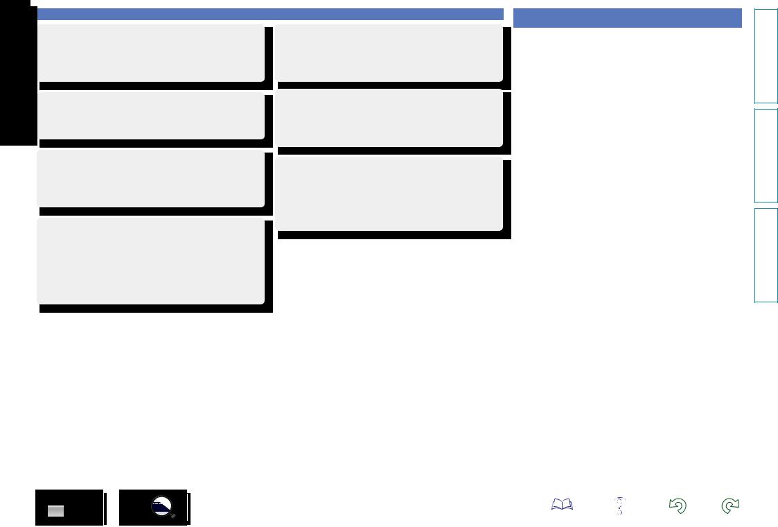
Accessories
Check that the following parts are supplied with the product.
q Getting Started......................................................................... |
|
1 |
w CD-ROM (Owner’s manual)..................................................... |
|
1 |
e Safety Instructions................................................................... |
|
1 |
r Warranty (for North America model only) |
................................ 1 |
|
t Service network list................................................................. |
|
1 |
y Power cord............................................................................... |
|
1 |
u Remote control unit (RC-1166)................................................ |
|
1 |
i R6/AA batteries........................................................................ |
|
2 |
o Setup microphone (ACM1HB)................................................. |
|
1 |
Q0AM loop antenna...................................................................... |
|
1 |
Q1FM indoor antenna................................................................... |
|
1 |
y |
u |
o |
Q0 Q1
Features
Digital video processor up-scales analog video signals (SD resolution) to 4K
This unit is equipped with the 4K video upscaling function, which allows for outputting analogue or SD (standard video quality) video to HDMI at 4K (3840 × 2160 pixels). This enables the unit and a TV connected with a single HDMI cable and any video source to be reproduced precisely with HD level of quality.
DENON’s unique high quality playback technology “Denon Link HD”
By connecting to a DENON Blu-ray Disc player compatible with Denon Link HD, the sound localization becomes more precise, reproducing a clear and three-dimensional sound image. Because this unit makes the integrated circuits operate while sharing the same clock with the Blu-ray Disc player, the transmitted digital audio has less jitter. This effect applies to any media audio source from the Blu-ray Disc player.
With a discrete-circuit configuration, the power amplifier provides identical quality for all 7 channels (165 W x 7ch)
The unit is equipped with a power amplifier that reproduces highfidelity sound in sound mode with equal quality and power for all channels, true to the original sound.
The power amplifier circuit adopts a discrete-circuit configuration that achieves high-quality surround sound reproduction.
Supports internet radio, music, and photograph streaming
Supports AirPlay® (vpage 73)
You can enjoy a wide variety of content, including listening to Internet radio, playing the audio files stored on your PC, and displaying on a TV the photographs stored on your PC.
This unit also supports AirPlay that lets you stream your music library from an iPhone, iPad, iPod touch or iTunes.
Equipped with “Hybrid PLL Jitter Reducer” capable of reducing jitter and phase noise that negatively affect sound quality
“Hybrid PLL Jitter Reducer” provided with this unit improves the sound localization, reproducing a natural sound field.
Equipped with a Multi-Zone Function 3 source, 3 zone output (incl.HDMI output for ZONE2)
This unit is equipped with a multi-zone function, so you can enjoy separate sound sources in three rooms including MAIN ZONE. Furthermore, this unit is equipped with an HDMI ZONE2 OUT connector, so you can play back in ZONE2 a video that is different from the one played back in MAIN ZONE.
Compatible with “Denon Remote App” for performing basic operations of the unit with an iPad, iPhonez1 or Android smartphone
“Denon Remote App” is application software that allows you to perform basic operations with an iPad, iPhone, Android smartphone or Android tablet such as turning the unit ON/OFF, controlling the volume, and switching the source.
z1 Download “Denon Remote App” from iTunes® App Store. The unit needs to be connected to a LAN and the iPhone/iPod touch needs to be connected to the same network by Wi-Fi (wireless LAN).
vSee overleaf
version Basic
version Advanced
Informations
2
“Setup Assistant”, providing easy-to-follow setup instructions
First select the language when prompted. Then simply follow the instructions displayed on the TV screen to set up the speakers, network, etc.
Easy to use, Graphical User Interface
This unit is equipped with an easy to see “Graphical User Interface” that uses menu displays and levels. The use of level displays increases operability of the this unit.
HDMI connectors enable connection to various digital AV devices (input: 7, output: 3)
The unit is equipped with 7 HDMI input connectors for connecting devices with HDMI connectors, such as a Blu-ray Disc player, game machine, HD digital camcorder, etc.
Supports HDMI (3D, ARC, Deep Color, “x.v.Color”, Auto Lip Sync, 4K) and HDMI control function (vpage 8)
In addition to HDMI 3D and ARC (Audio Return Channel) functions, this unit supports the video pass-through function, which outputs video to TV without changing the video quality when video signals of 4K (3840×2160 pixels) are input, and the GUI overlay function, which overlays the menu screen (GUI) on the 4K video screen.
Features
Simultaneous playback on two HDMI channels (except for ZONE2 HDMI output)
This unit is equipped with two HDMI MONITOR outputs. You can connect one output to a projector and the other output to a TV for simultaneous signal outputs.
Direct play for iPod® and iPhone® via USB (vpage 21)
Music data from an iPod can be played back if you connect the USB cable supplied with the iPod via the USB port of this unit, and also an iPod can be controlled with the remote control unit for this unit.
Audyssey DSX®
This unit is equipped with Audyssey DSX® processor. By connecting front height speakers to this unit and playing back through Audyssey DSX®, you can experience a more powerful playback expression in the height audio range. By connecting front wide speakers, you can experience a more powerful playback expression in the wide audio range.
Cautions on handling
•Before turning the power on
Check once again that all connections are correct and that there are no problems with the connection cables.
•Power is supplied to some of the circuitry even when the unit is set to the standby mode. When going on vacation or leaving home for long periods of time, be sure to unplug the power cord from the power outlet.
•About condensation
If there is a major difference in temperature between the inside of the unit and the surroundings, condensation (dew) may form on the operating parts inside the unit, causing the unit not to operate properly.
If this happens, let the unit sit for an hour or two with the power turned off and wait until there is little difference in temperature before using the unit.
•Cautions on using mobile phones
Using a mobile phone near this unit may result in noise. If that occurs, move the mobile phone away from this unit when it is in use.
•Moving the unit
Turn off the power and unplug the power cord from the power outlet. Next, disconnect the connection cables to other system units before moving the unit.
•About care
•Wipe the cabinet and control panel clean with a soft cloth.
•Follow the instructions when using a chemical cleaner.
•Benzene, paint thinner or other organic solvents as well as insecticide may cause material changes and discoloration if brought into contact with the unit, and should therefore not be used.
version Basic
version Advanced
Informations
3
Basic version
Basic version
Here, we explain the connections and basic operation methods for this unit.
FConnections vpage 5
FSetup vpage 29
FPlayback (Basic operation) vpage 36
FSelecting a listening mode (Sound Mode) vpage 75
4
version Basic
version Advanced
Informations
Connections
Important information
Make connections before using this unit.
To create a home theater that can play back higher quality video and audio by fully utilizing the capabilities of this unit and your video devices, connect this unit to each of your video devices with HDMI cables.
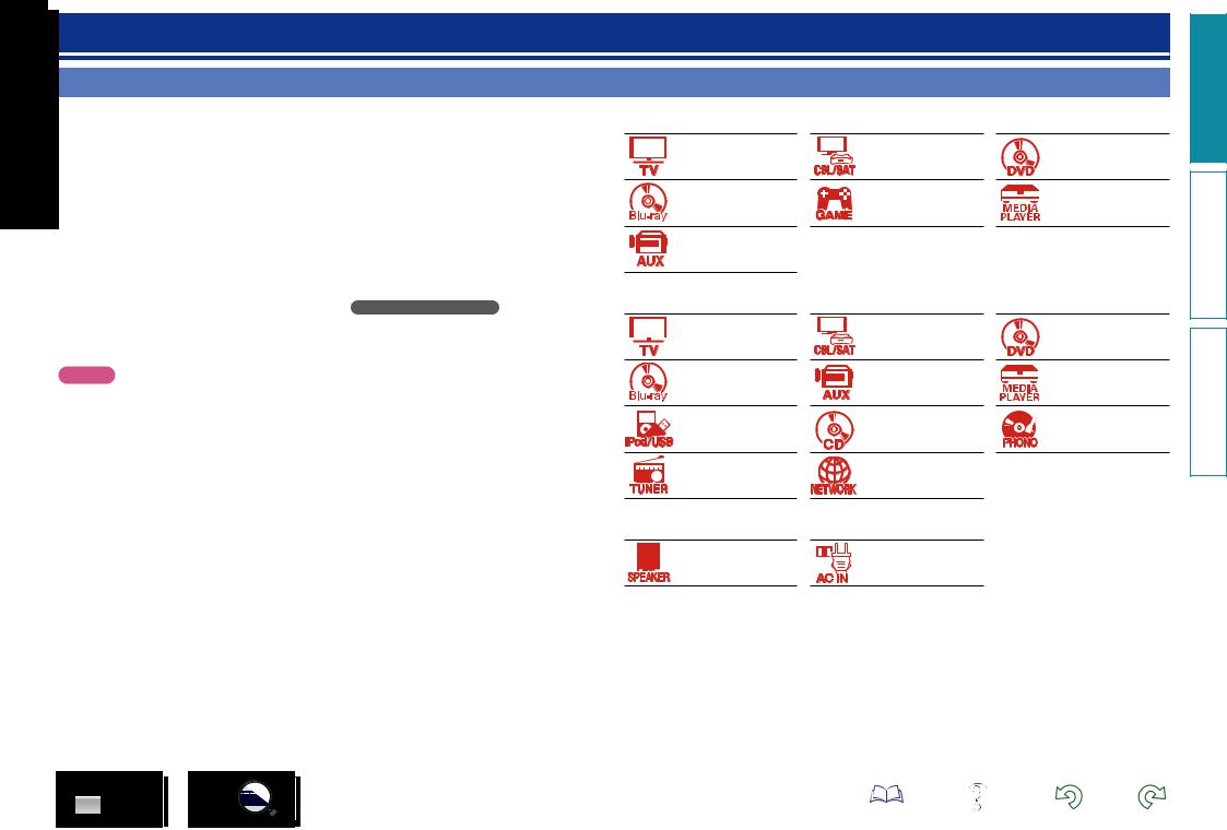
nnHDMI-compatible device
If your video device does not support HDMI connections, use the following connection.
nnHDMI-incompatible device
nnHDMI-compatible device
vpage 9 |
vpage 11 |
vpage 11 |
vpage 11 |
vpage 11 |
vpage 11 |
vpage 11 |
|
|
This unit can change the source that is assigned to the DIGITAL AUDIO IN and COMPONENT VIDEO IN connectors.
You can change the source for connectors listed in Input connector setting within pages that describe connections for devices.
For details on assigning a source to connectors, see “Changing the source assigned to connectors” (vpage 14). For the setting method, see “Input Assign” (vpage 125).
nnHDMI-incompatible device
vpage 15 |
vpage 16 |
vpage 18 |
NOTE
•The menu screen is only displayed on TV connected to this unit via HDMI. If your TV is connected to this unit via other video output connectors, perform menu operations while seeing the display on this unit.
•Do not plug in the power cord until all connections have been completed. However, when the “Setup Assistant” is running, follow the instructions in the “Setup Assistant” (C page 7) screen for making connections. (During “Setup Assistant” operation, the input/output connectors do not conduct current.)
•When running the “Setup Assistant” (C page 7), turn off the power supply of connected devices.
•When making connections, also refer to the operating instructions of the other devices being connected.
•Be sure to connect the left and right channels properly (left with left, right with right).
•Do not bundle power cords together with connection cables. Doing so can result in noise.
vpage 18 |
vpage 19 |
vpage 20 |
vpage 21 |
vpage 22 |
vpage 23 |
vpage 24 |
vpage 27 |
|
nnOthers
vpage 84 |
vpage 28 |
version Basic
version Advanced
Informations
5
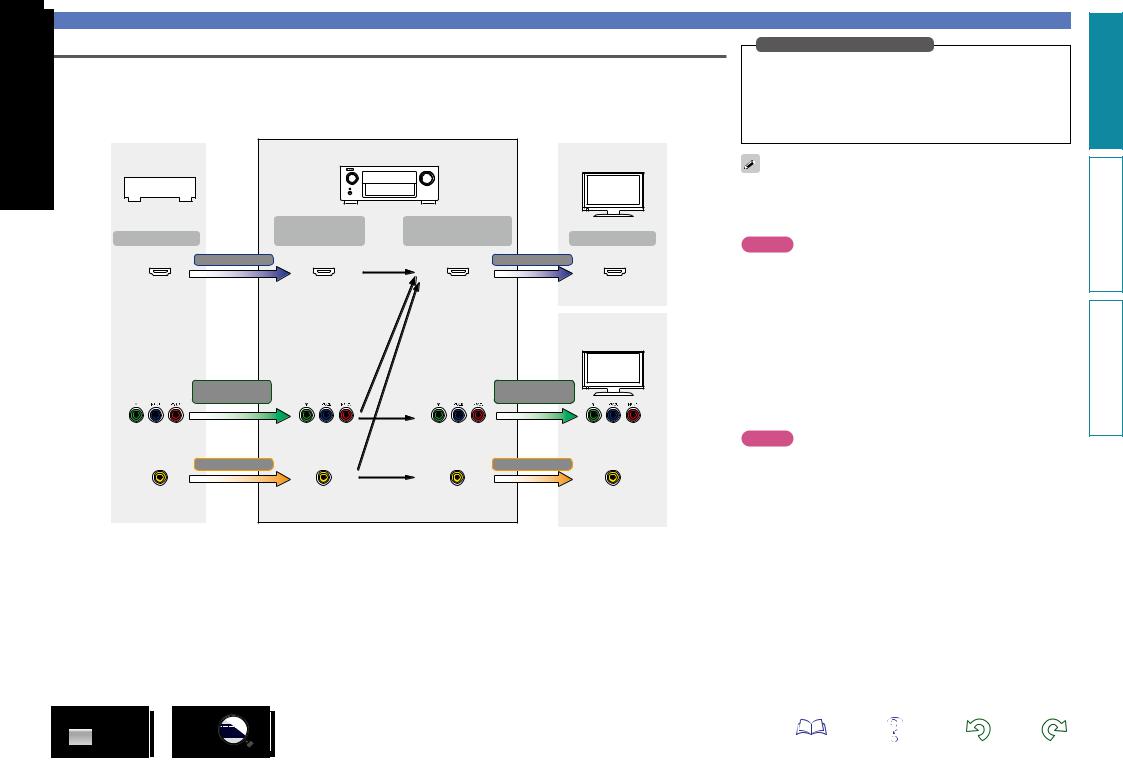
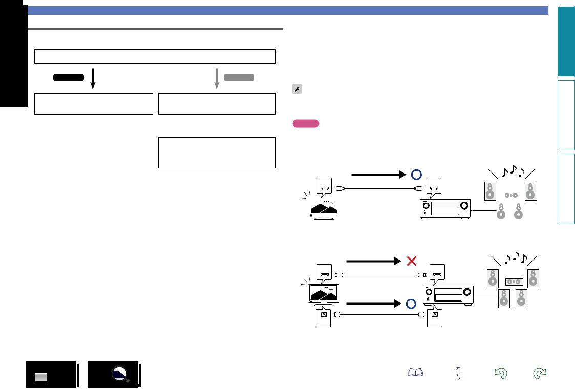
Converting input video signals for output (Video conversion function)
This unit is equipped with three types of video input connectors (HDMI, Component video and video) and three types of video output connectors (HDMI, Component video and video).
This function automatically converts various formats of video signals input to this unit into the formats used to output the video signals from this unit to a monitor.
GFlow of video signals for MAIN ZONEH
Video device |
|
This unit |
HDMI-compatible TV |
|
|
||
|
|
|
|
|
Input |
Output |
|
Output |
(IN) |
(MONITOR OUT) |
Input |
HDMI signal |
|
|
HDMI signal |
HDMI connector |
HDMI connector |
HDMI connector |
HDMI connector |
|
|
|
HDMI-incompatible |
|
|
|
TV |
Component video |
|
|
Component video |
signal |
|
|
signal |
Component video |
Component video |
Component video |
Component video |
connectors |
connectors |
connectors |
connectors |
Video signal |
|
|
Video signal |
Video connector |
Video connector |
Video connector |
Video connector |
Important information
Make Settings as Necessary
•If you do not want this unit to convert video signals automatically, use the following setting item to disable this function.
“Video Conversion” (vpage 121)
•If you want to change the resolution of video signals output to the TV, use the following setting item to do so.
“Resolution” (vpage 122)
•The video conversion function supports the NTSC, PAL, SECAM, NTSC 4.43, PAL-N, PAL-M and PAL-60 formats.
•Resolutions of HDMI-compatible TVs can be checked at “Video” – “Monitor” (vpage 142).
NOTE
•The menu screen is only displayed on TV connected to this unit via HDMI. If your TV is connected to this unit via other video output connectors, perform menu operations while seeing the display on this unit.
•HDMI signals are digital. HDMI signals cannot be converted into analog signals.
•When a non-standard video signal from a game machine or some other source is input, the video conversion function might not operate.
NOTE
•HDMI signals are digital. HDMI signals cannot be converted into analog signals.
•The HDMI ZONE function is only compatible with the HDMI 1-6 IN connectors. It is not compatible with the HDMI 7 IN connector.
For example, if you connect this unit to an HDMI-compatible TV with a single HDMI cable, this unit automatically converts input signals other than HDMI video signals to HDMI signals to output from the HDMI connector to the TV. This unit outputs only one type of video signals, so video signals output from this unit to the TV remain unchanged even if you switch to a device that outputs another type of video signals for playback. Therefore, you do not need to switch the video input on the TV. Furthermore, this unit converts the input analog video signals such as video and component video signals to high resolution digital HDMI video signals for output, improving the quality of the video.
If your TV does not support HDMI connections, connect this unit to TV with analog video connectors. This unit can not convert HDMI input signals to analog video signals, so when inputting from an HDMI device, use component video or video input connectors.
version Basic
version Advanced
Informations
6
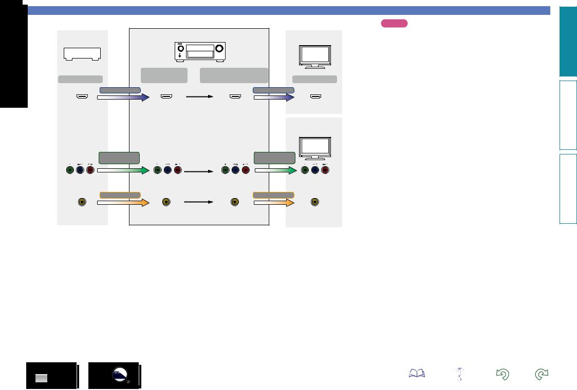
GFlow of video signals for ZONE2H
Video device |
|
This unit |
HDMI-compatible TV |
|
|
||
|
|
|
|
|
Input |
Output |
|
Output |
(IN) |
(ZONE2 MONITOR OUT) |
Input |
HDMI signal |
|
HDMI signal |
|
HDMI connector |
HDMI connector |
HDMI connector |
HDMI connector |
|
|
|
HDMI-incompatible |
|
|
|
TV |
Component video |
|
Component video |
|
signal |
|
signal |
|
Component video |
Component video |
Component video |
Component video |
connectors |
connectors |
connectors |
connectors |
Video signal |
|
Video signal |
|
Video connector |
Video connector |
Video connector |
Video connector |
Important information
NOTE
•HDMI signals are digital. HDMI signals cannot be converted into analog signals.
•The HDMI ZONE function is only compatible with the HDMI 1-6 IN connectors. It is not compatible with the HDMI 7 IN connector.
version Basic
version Advanced
Informations
7
Connecting an HDMI-compatible device
You can connect up to ten HDMI-compatible devices (7-inputs/3-outputs) to the unit.
When a TV is connected to the HDMI ZONE2 OUT connector, you can play back a video or audio from the device connected to the HDMI 1 - 6 IN connector in ZONE2 ( vpage 103).
If the device connected to this unit is equipped with an HDMI connector, it is recommended to use HDMI connections. Connections with an HDMI cable offer the following benefits that can not be achieved with other connection methods.
•High quality playback by transmitting audio and video via digital signals
HDMI connections can transmit high definition video and high quality audio formats adopted by Bluray disc players (Dolby Digital Plus, Dolby TrueHD, dts-HD, dts-HD Master Audio).
HDMI connections also convey information required for playback between devices. The information is used for copyright protection and TV resolution recognition, the ARC function, the HDMI control function, etc.
•Transmission of audio and video signals with a single HDMI cable
Previous connections require multiple audio and video cables, but HDMI connections require only a single HDMI cable to transmit audio and video signals. This allows wires in a home theater system, which tend to be complicated, to be more organized.
•Mutual control through the HDMI control function (vpage 95)
This unit and the HDMI device connected via HDMI can be linked to perform operations such as power control, volume control, and input source switching.
•Other video and audio functions, such as 3D video playback, Content Type, the ARC function, are supported (vpage 12).
•There is more than one version of HDMI standard. The supported functions and the performance vary according to the version. This unit complies with the HDMI standard, supporting the ARC and 3D playback functions. To enjoy these functions, the HDMI device connected to this unit also needs to use the same version of the standard. For the version of the HDMI standard on the device connected to this unit, see the device’s manual.
•Some TVs do not support audio input via HDMI connections. For details, see your TV’s manual.
nn Before connecting this unit to TV via HDMI connections (vpage 9) nn Connecting this unit to a TV via HDMI connections (vpage 10)
nn Connecting this unit to video devices via HDMI connections (vpage 11)
nn HDMI function (vpage 12)
nn Settings related to HDMI connections (vpage 13)
version Basic
version Advanced
Informations
8
Before connecting this unit to TV via HDMI connections
There are 2 methods to connect HDMI-compatible TV to this unit.
Use the connection method that suits your TV.
Does the TV to be connected to this unit support the ARC function?
Yes
Connecting this unit to a TV via HDMI connections (vpage 10)
No
Connecting this unit to a TV via HDMI connections (vpage 10)
+
Connecting a TV (vpage 15)
For audio connections, use a method other than HDMI connections.
Connecting an HDMI-compatible device
nnAbout ARC (Audio Return Channel) function
This function plays TV audio on this unit by sending the TV audio signal to this unit via HDMI cable.
If a TV without the ARC function is connected via HDMI connections, video signals of the playback device connected to this unit are transmitted to the TV, but this unit can not play back the audio from the TV. If you want to enjoy surround audio for TV program, a separate audio cable connection is required.
In contrast, if a TV with the ARC function is connected via HDMI connections, no audio cable connection required. Audio signals from the TV can be input to this unit through the HDMI cable between this
and the TV. This function allows you to enjoy surround playback on this unit for the TV.
When the ARC function is used, connect a device with a “Standard HDMI cable with Ethernet” or “High Speed HDMI cable with Ethernet” for HDMI.
Refer to the owner’s manual for your TV for details about TV connection and settings.
NOTE
The HDMI ZONE2 OUT connector is not compatible with the ARC function.
GConnection to a TV with the ARC functionH
Audio from the TV
Audio signals from the TV
IN |
OUT |
|
|
|
|
|
|
|
|
|
|
|
|
|
|
|
|
|
|
|
|
|
|
|
|
|
|
|
|
|
|
|
|
|
|
|
|
|
|
|
|
|
|
|
|
|
|
|
|
|
|
|
|
|
|
|
|
|
|
|
|
|
|
|
|
|
|
|
|
|
|
|
|
|
|
|
|
|
|
|
|
|
|
|
|
|
|
|
|
|
|
|
|
|
|
|
|
|
|
|
|
|
|
|
|
|
|
|
TV |
|
This unit |
|
Speakers |
||||||||
GConnection to a TV without the ARC functionH
Audio from the TV
Audio signals from the TV
IN |
|
OUT |
|
Audio signals from the TV |
|
OUT |
Optical cable |
IN |
version Basic
version Advanced
Informations
9
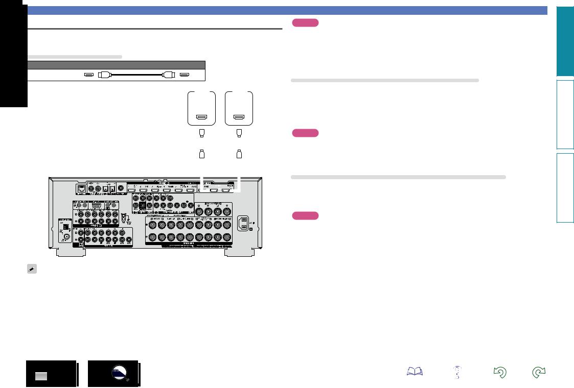
Connecting this unit to a TV via HDMI connections
When a TV is connected to the HDMI ZONE2 OUT connector, you can play back a video or audio from the device connected to the HDMI 1 - 6 IN connector in ZONE2 ( vpage 103).
Cables used for connections
Audio and video cable (sold separately)
HDMI cable
|
|
|
|
|
|
|
|
|
|
|
|
|
|
|
|
|
|
|
|
|
|
|
|
|
|
|
|
|
|
|
|
|
|
|
|
|
|
|
|
|
|
|
|
|
|
|
|
|
|
|
|
|
|
|
|
|
|
|
|
|
|
|
|
|
|
|
|
|
|
|
|
|
|
|
|
|
|
|
|
|
|
|
|
|
|
|
|
|
|
|
|
|
|
|
|
|
|
|
|
|
|
|
|
|
|
|
|
|
|
|
|
|
|
|
|
|
|
|
|
|
|
|
|
|
|
|
|
|
|
TV 1 |
|
|
|
|
|
|
|
TV 2 |
|
|
|
|
|||||||
|
|
|
|
|
|
|
|
|
|
|
|
|
|
|
|
|
|
|
|
|
|
|
|
|
|
|
|
|
|
|
|
|
|
|
|
|
|
|
|
|
|
|
|
|
|
|
|
|
|
|
|
|
|
|
|
|
|
|
|
|
|
|
|
|
||||||||||
|
|
|
|
|
|
|
|
|
|
|
|
|
|
|
|
|
|
|
|
|
|
|
|
|
|
|
|
|
|
|
|
|
|
|
|
|
|
|
|
|
|
|
|
|
|
|
|
|
|
|
|
|
|
|
|
HDMI |
|
|
|
|
|
|
|
HDMI |
|
|
||||||||
|
|
|
|
|
|
|
|
|
|
|
|
|
|
|
|
|
|
|
|
|
|
|
|
|
|
|
|
|
|
|
|
|
|
|
|
|
|
|
|
|
|
|
|
|
|
|
|
|
|
|
|
|
|
|
|
|
|
IN |
|
|
|
|
|
|
|
|
IN |
|
|
|||||
|
|
|
|
|
|
|
|
|
|
|
|
|
|
|
|
|
|
|
|
|
|
|
|
|
|
|
|
|
|
|
|
|
|
|
|
|
|
|
|
|
|
|
|
|
|
|
|
|
|
|
|
|
|
|
(ARC) |
|
|
|
|
|
|
(ARC) |
|
|
||||||||||
|
|
|
|
|
|
|
|
|
|
|
|
|
|
|
|
|
|
|
|
|
|
|
|
|
|
|
|
|
|
|
|
|
|
|
|
|
|
|
|
|
|
|
|
|
|
|
|
|
|
|
|
|
|
|
|
|
|
|
|
|
|
|
|
|
|
|
|
|
|
|
|
|
|
|
|
|
|
|
|
|
|
|
|
|
|
|
|
|
|
|
|
|
|
|
|
|
|
|
|
|
|
|
|
|
|
|
|
|
|
|
|
|
|
|
|
|
|
|
|
|
|
|
|
|
|
|
|
|
|
|
|
|
|
|
|
|
|
|
|
|
|
|
|
|
|
|
|
|
|
|
|
|
|
|
|
|
|
|
|
|
|
|
|
|
|
|
|
|
|
|
|
|
|
|
|
|
|
|
|
|
|
|
|
|
|
|
|
|
|
|
|
|
|
|
|
|
|
|
|
|
|
|
|
|
|
|
|
|
|
|
|
|
|
|
|
|
|
|
|
|
|
|
|
|
|
|
|
|
|
|
|
|
|
|
|
|
|
|
|
|
|
|
|
|
|
|
|
|
|
|
|
|
|
|
|
|
|
|
|
|
|
|
|
|
|
|
|
|
|
|
|
|
|
|
|
|
|
|
|
|
|
|
|
|
|
|
|
|
|
|
|
|
|
|
|
|
|
|
|
|
|
|
|
|
|
|
|
|
|
|
|
|
|
|
|
|
|
|
|
|
|
|
|
|
|
|
|
|
|
|
|
|
|
|
|
|
|
|
|
|
|
|
|
|
|
|
|
|
|
|
|
|
|
|
|
|
|
|
|
|
|
|
|
|
|
|
|
|
|
|
|
|
|
|
|
|
|
|
|
|
|
|
|
|
|
|
|
|
|
|
|
|
|
|
|
|
|
|
|
|
|
|
|
|
|
|
|
|
|
|
|
|
|
|
|
|
|
|
|
|
|
|
|
|
|
|
|
|
|
|
|
|
|
|
|
|
|
|
|
|
|
|
|
|
|
|
|
|
|
|
|
|
|
|
|
|
|
|
|
|
|
|
|
|
|
|
|
|
|
|
|
|
|
|
|
|
|
|
|
|
|
|
|
|
|
|
|
|
|
|
|
|
|
|
|
|
|
|
|
|
|
|
|
|
|
|
|
|
|
|
|
|
|
|
|
|
|
|
|
|
|
|
|
|
|
|
|
|
|
|
|
|
|
|
|
|
|
|
|
|
|
|
|
|
|
|
|
|
|
|
|
|
|
|
|
|
|
|
|
|
|
|
|
|
|
|
|
|
|
|
|
|
|
|
|
|
|
|
|
|
|
|
|
|
|
|
|
|
|
|
|
|
|
|
|
|
|
|
|
|
|
|
|
|
|
|
|
|
|
|
|
|
|
|
|
|
|
|
|
|
|
|
|
|
|
|
|
|
|
|
|
|
|
|
|
|
|
|
|
|
|
|
|
|
|
|
|
|
|
|
|
|
|
|
|
|
|
|
|
|
|
|
|
|
|
|
|
|
|
|
|
|
|
|
|
|
|
|
|
|
|
|
|
|
|
|
|
|
|
|
|
|
|
|
|
|
|
|
|
|
|
|
|
|
|
|
|
|
|
|
|
|
|
|
|
|
|
|
|
|
|
|
|
|
|
|
|
|
|
|
|
|
|
|
|
|
|
|
|
|
|
|
|
|
|
|
|
|
|
|
|
|
|
|
|
|
|
|
|
|
|
|
|
|
|
|
|
|
|
|
|
|
|
|
|
|
|
|
|
|
|
|
|
|
|
|
|
|
|
|
|
|
|
|
|
|
|
|
|
|
|
|
|
|
|
|
|
|
|
|
|
|
|
|
|
|
|
|
|
|
|
|
|
|
|
|
|
|
|
|
|
|
|
|
|
|
|
|
|
|
|
|
|
|
|
|
|
|
|
|
|
|
|
|
|
|
|
|
|
|
|
|
|
|
|
|
|
|
|
|
|
|
|
|
|
|
|
|
|
|
|
|
|
|
|
|
|
|
|
|
|
|
|
|
|
|
|
|
|
|
|
|
|
|
|
|
|
|
|
|
|
|
|
|
|
|
|
|
|
|
|
|
|
|
|
|
|
|
|
|
|
|
|
|
|
|
|
|
|
|
|
|
|
|
|
|
|
|
|
|
|
|
|
|
|
|
|
|
|
|
|
|
|
|
|
|
|
|
|
|
|
|
|
|
|
|
|
|
|
|
|
|
|
|
|
|
|
|
|
|
|
|
|
|
|
|
|
|
|
|
|
|
|
|
|
|
|
|
|
|
|
|
|
|
|
|
|
|
|
|
|
|
|
|
|
|
|
|
|
|
|
|
|
|
|
|
|
|
|
|
|
|
|
|
|
|
|
|
|
|
|
|
|
|
|
|
|
|
|
|
|
|
|
|
|
|
|
|
|
|
|
|
|
|
|
|
|
|
|
|
|
|
|
|
|
|
|
|
|
|
|
|
|
|
|
|
|
|
|
|
|
|
|
|
|
|
|
|
|
|
|
|
|
|
|
|
|
|
|
|
|
|
|
|
|
|
|
|
|
|
|
|
|
|
|
|
|
|
|
|
|
|
|
|
|
|
|
|
|
|
|
|
|
|
|
|
|
|
|
|
|
|
|
|
|
|
|
|
|
|
|
|
|
|
|
|
|
|
|
|
|
|
|
|
|
|
|
|
|
|
|
|
|
|
|
|
|
|
|
|
|
|
|
|
|
|
|
|
|
|
|
|
|
|
|
|
|
|
|
|
|
|
|
|
|
|
|
|
|
|
|
|
|
|
|
|
|
|
|
|
|
|
|
|
|
|
|
|
|
|
|
|
|
|
|
|
|
|
|
|
|
|
|
|
|
|
|
|
|
|
|
|
|
|
|
|
|
|
|
|
|
|
|
|
|
|
|
|
|
|
|
|
|
|
|
|
|
|
|
|
|
|
|
|
|
|
|
|
|
|
|
|
|
|
|
|
|
|
|
|
|
|
|
|
|
|
|
|
|
|
|
|
|
|
|
|
|
|
|
|
|
|
|
|
|
|
|
|
|
|
|
|
|
|
|
|
|
|
|
|
|
|
|
|
|
|
|
|
|
|
|
|
|
|
|
|
|
|
|
|
|
|
|
|
|
|
|
|
|
|
|
|
|
|
|
|
|
|
|
|
|
|
|
|
|
|
|
|
|
|
|
|
|
|
|
|
|
|
|
|
|
|
|
|
|
|
|
|
|
|
|
|
|
|
|
|
|
|
|
|
|
|
|
|
|
|
|
|
|
|
|
|
|
|
|
|
|
|
|
|
|
|
|
|
|
|
|
|
|
|
|
|
|
|
|
|
|
|
|
|
|
|
|
|
|
|
|
|
|
|
|
|
|
|
|
|
|
|
|
|
|
|
|
|
|
|
|
|
|
|
|
|
|
|
|
|
|
|
|
|
|
|
|
|
|
|
|
|
|
|
|
|
|
|
|
|
|
|
|
|
|
|
|
|
|
|
|
|
|
|
|
|
|
|
|
|
|
|
|
|
|
|
|
|
|
|
|
|
|
|
|
|
|
|
|
|
|
|
|
|
|
|
|
|
|
|
|
|
|
|
|
|
|
|
|
|
|
|
|
|
|
|
|
|
|
|
|
|
|
|
|
|
|
|
|
|
|
|
|
|
|
|
|
|
|
|
|
|
|
|
|
|
|
|
|
|
|
|
|
|
|
|
|
|
|
|
|
|
|
|
|
|
|
|
|
|
|
|
|
|
|
|
|
|
|
|
|
|
|
|
|
|
|
|
|
|
|
|
|
|
|
|
|
|
|
|
|
|
|
|
|
|
|
|
|
|
|
|
|
|
|
|
|
|
|
|
|
|
|
|
|
|
|
|
|
|
|
|
|
|
|
|
|
|
|
|
|
|
|
|
|
|
|
|
|
|
|
|
|
|
|
|
|
|
|
|
|
|
|
|
|
|
|
|
|
|
|
|
|
|
|
|
|
|
|
|
|
|
|
|
|
|
|
|
|
|
|
|
|
|
|
|
|
|
|
|
|
|
|
|
|
|
|
|
|
|
|
|
|
|
|
|
|
|
|
|
|
|
|
|
|
|
|
|
|
|
|
|
|
|
|
|
|
|
|
|
|
|
|
|
|
|
|
|
|
|
|
|
|
|
|
|
|
|
|
|
|
|
|
|
|
|
|
|
|
|
|
|
|
|
|
|
|
|
|
|
|
|
|
|
|
|
|
|
|
|
|
|
|
|
|
|
|
|
|
|
|
|
|
|
|
|
|
|
|
|
|
|
|
|
|
|
|
|
|
|
|
|
|
|
|
|
|
|
|
|
|
|
|
|
|
|
|
|
|
|
|
|
|
|
|
|
|
|
|
|
|
|
|
|
|
|
|
|
|
|
|
|
|
|
|
|
|
|
|
|
|
|
|
|
|
|
|
|
|
|
|
|
|
|
|
|
|
|
|
|
|
|
|
|
|
|
|
|
|
|
|
|
|
|
|
|
|
|
|
|
|
|
|
|
|
|
|
|
|
|
|
|
|
|
|
|
|
|
|
|
|
|
|
|
|
|
|
|
•Video signals are not output if the input video signals do not match the monitor’s resolution. In this case, switch the Blu-ray Disc/DVD player’s resolution to a resolution with which the monitor is compatible.
•When this unit and monitor are connected with an HDMI cable, if the monitor is not compatible with HDMI audio signal playback, only the video signals are output to the monitor. Make audio connections (vpage 15 “Connecting a TV”).
Connecting an HDMI-compatible device
NOTE
•The audio signal from the HDMI output connector (sampling frequency, number of channels, etc.) may be limited by the HDMI audio specifications of the connected device regarding permissible inputs.
•When connecting a TV that does not support the ARC function, an audio cable connection is required in addition to the HDMI cable. In this case, refer to “Connecting a TV” (vpage 15) for the connection method.
For the ARC function, see “About ARC (Audio Return Channel) function” (vpage 9).
Connecting to a device equipped with a DVI-D connector
The DVI-D (Digital Visual Interface) method is also used for video transmission via digital signals. This is developed mainly for computers, and some AV devices such as projectors are equipped with this interface. To output HDMI video signals to a DVI-D video input compatible device, use an HDMI/DVI conversion cable, which converts HDMI video signals to DVI signals.
The DVI-D connector can transmit high quality digital signals, but the copy guard and other issues may hinder normal operations for some device combinations.
NOTE
•No sound is output when connected to a device equipped with a DVI-D connector. Make audio connections as described in “Connecting a TV” (vpage 15).
•Signals cannot be output to DVI-D devices that do not support HDCP.
•Depending on the combination of devices, the video signals may not be output.
Settings required when using a TV that supports the ARC function
When using a TV that supports the ARC function, make the following settings.
•Set “HDMI Control” (vpage 121) to “On”.
•Set “Control Monitor” (vpage 121) to match the number of the HDMI MONITOR connector connected to the TV that supports the ARC function.
NOTE
If the TV that supports the ARC function is connected to both HDMI MONITOR 1 and HDMI MONITOR 2 connectors, you cannot use ARC function at the same time.
version Basic
version Advanced
Informations
10
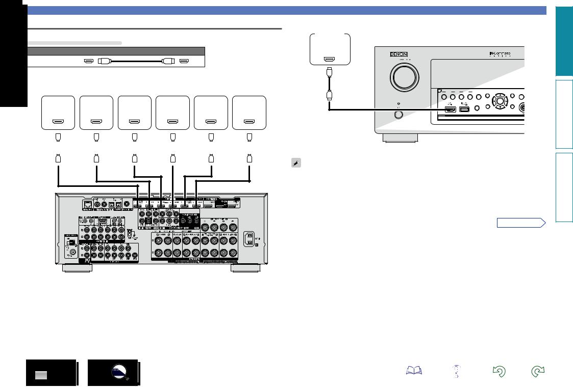
Connecting this unit to video devices via HDMI connections
Cables used for connections
Audio and video cable (sold separately)
HDMI cable
• This interface allows transfer of digital video signals and digital audio signals over a single HDMI cable.
|
|
|
|
|
|
|
|
|
|
Blu-ray |
|
|
|
|
|
|
|
|
|
Digital |
||||
|
|
|
|
|
|
|
|
|
|
|
|
|
|
|
|
|
|
|
||||||
|
|
Set-top |
|
|
|
|
|
Disc |
|
|
|
|
|
|
|
|
|
camcorder |
||||||
|
|
DVD |
|
|
Game |
|
Media |
|||||||||||||||||
|
|
box |
|
player |
|
player |
|
console |
|
player |
|
(Secondary) |
||||||||||||
|
|
HDMI |
HDMI |
HDMI |
|
HDMI |
HDMI |
|
HDMI |
|||||||||||||||
|
|
OUT |
OUT |
OUT |
|
OUT |
OUT |
|
OUT |
|||||||||||||||
|
|
|
|
|
|
|
|
|
|
|
|
|
|
|
|
|
|
|
|
|
|
|
|
|
|
|
|
|
|
|
|
|
|
|
|
|
|
|
|
|
|
|
|
|
|
|
|
|
|
|
|
|
|
|
|
|
|
|
|
|
|
|
|
|
|
|
|
|
|
|
|
|
|
|
|
|
|
|
|
|
|
|
|
|
|
|
|
|
|
|
|
|
|
|
|
|
|
|
|
|
|
|
|
|
|
|
|
|
|
|
|
|
|
|
|
|
|
|
|
|
|
|
|
|
|
|
|
|
|
|
|
|
|
|
|
|
|
|
|
|
|
|
|
|
|
|
|
|
|
Digital camcorder (Primary)
HDMI
OUT
Connecting an HDMI-compatible device
version Basic
ZONE 2 |
ZONE 3 |
|
INFO |
OPTION |
versionAdvanced |
||
ON/OFF |
SOURCE SELECT |
ON/OFF |
SOURCE SELECT |
STATUS |
|
|
DIMMER |
|
REC SOURCE |
|
|
|
ENTER |
|
VID |
|
|
|
PHONES |
BACK |
SETUP |
|
|
GFront panelH
•When this unit is connected to other devices with HDMI cables, connect this unit and TV also with an HDMI cable.
•When connecting a device that supports Deep Color or 4K, please use a “High Speed HDMI cable” or “High Speed HDMI cable with Ethernet”.
•Video signals are not output if the input video signals do not match the monitor’s resolution. In this case, switch the Blu-ray Disc/DVD player’s resolution to a resolution with which the monitor is compatible.
vSee overleaf
Informations
GRear panelH
11
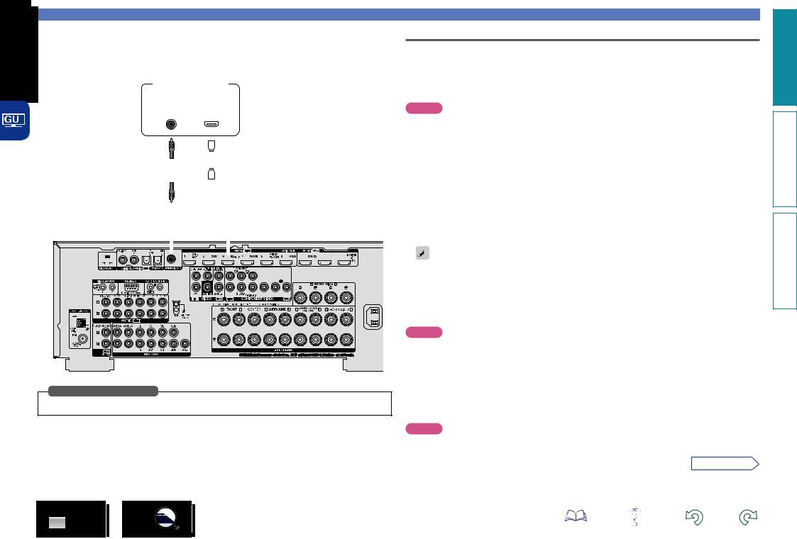
nnConnecting a player compatible with the Denon Link HD function
By making a Denon Link HD connection to a player compatible with the Denon Link HD function, you can enjoy higher quality playback compared with when only the HDMI connector connection is made. For the playback method, see “Playing a Blu-ray Disc player compatible with Denon Link HD” (vpage 37).
Blu-ray Disc player
|
|
|
|
|
|
|
|
|
|
|
|
|
|
|
|
|
|
|
|
|
|
|
|
|
|
|
|
|
|
|
|
|
|
|
|
|
|
|
|
|
|
|
|
|
|
|
|
|
|
|
|
|
|
|
|
|
|
|
|
|
|
|
|
|
|
|
|
|
|
|
|
|
|
|
|
|
|
|
|
|
|
|
|
|
|
|
|
|
|
|
|
|
|
|
|
Denon |
|
|
|
|
|
|
|
|
|
HDMI |
|
|
|
|
|
|
|
|
|
|
|
|
|
|
|
|
|
|
|
|
|
|
|
|
|
|
|
|
|
|
|||||||
|
|
|
|
|
|
|
|
|
|
|
|
|
|
|
|
|
|
|
|
|
|
|
|
Link HD |
|
|
|
|
|
|
|
|
|
OUT |
|
|
|
|
|
|
|
|
|
|
|
|
|
|
|
|
|
|
|
|
|
|
|
|
|
|
|
|
|
|
|||||||
|
|
|
|
|
|
|
|
|
|
|
|
|
|
|
|
|
|
|
|
|
|
|
|
|
|
|
|
|
|
|
|
|
|
|
|
|
|
|
|
|
|
|
|
|
|
|
|
|
|
|
|
|
|
|
|
|
|
|
|
|
|
|
|
|
|
|
|
|
|
|
|
|
|
|
|
|
|
|
|
|
|
|
|
|
|
|
|
|
|
|
|
|
|
|
|
|
|
|
|
|
|
|
|
|
|
|
|
|
|
|
|
|
|
|
|
|
|
|
|
|
|
|
|
|
|
|
|
|
|
|
|
|
|
|
|
|
|
|
|
|
|
|
|
|
|
|
|
|
|
|
|
|
|
|
|
|
|
|
|
|
|
|
|
|
|
|
|
|
|
|
|
|
|
|
|
|
|
|
|
|
|
|
|
|
|
|
|
|
|
|
|
|
|
|
|
|
|
|
|
|
|
|
|
|
|
|
|
|
|
|
|
|
|
|
|
|
|
|
|
|
|
|
|
|
|
|
|
|
|
|
|
|
|
|
|
|
|
|
|
|
|
|
|
|
|
|
|
|
|
|
|
|
|
|
|
|
|
|
|
|
|
|
|
|
|
|
|
|
|
|
|
|
|
|
|
|
|
|
|
|
|
|
|
|
|
|
|
|
|
|
|
|
|
|
|
|
|
|
|
|
|
|
|
|
|
|
|
|
|
|
|
|
|
|
|
|
|
|
|
|
|
|
|
|
|
|
|
|
|
|
|
|
|
|
|
|
|
|
|
|
|
|
|
|
|
|
|
|
|
|
|
|
|
|
|
|
|
|
|
|
|
|
|
|
|
|
|
|
|
|
|
|
|
|
|
|
|
|
|
|
|
|
|
|
|
|
|
|
|
|
|
|
|
|
|
|
|
|
|
|
|
|
|
|
|
|
|
|
|
|
|
|
|
|
|
|
|
|
|
|
|
|
|
|
|
|
|
|
|
|
|
|
|
|
|
|
|
|
|
|
|
|
|
|
|
|
|
|
|
|
|
|
|
|
|
|
|
|
|
|
|
|
|
|
|
|
|
|
|
|
|
|
|
|
|
|
|
|
|
|
|
|
|
|
|
|
|
|
|
|
|
|
|
|
|
|
|
|
|
|
|
|
|
|
|
|
|
|
|
|
|
|
|
|
|
|
|
|
|
|
|
|
|
|
|
|
|
|
|
|
|
|
|
|
|
|
|
|
|
|
|
|
|
|
|
|
|
|
|
|
|
|
|
|
|
|
|
|
|
|
|
|
|
|
|
|
|
|
|
|
|
|
|
|
|
|
|
|
|
|
|
|
|
|
|
|
|
|
|
|
|
|
|
|
|
|
|
|
|
|
|
|
|
|
|
|
|
|
|
|
|
|
|
|
|
|
|
|
|
|
|
|
|
|
|
|
|
|
|
|
|
|
|
|
|
|
|
|
|
|
|
|
|
|
|
|
|
|
|
|
|
|
|
|
|
|
|
|
|
|
|
|
|
|
|
|
|
|
|
|
|
|
|
|
|
|
|
|
|
|
|
|
|
|
|
|
|
|
|
|
|
|
|
|
|
|
|
|
|
|
|
|
|
|
|
|
|
|
|
|
|
|
|
|
|
|
|
|
|
|
|
|
|
|
|
|
|
|
|
|
|
|
|
|
|
|
|
|
|
|
|
|
|
|
|
|
|
|
|
|
|
|
|
|
|
|
|
|
|
|
|
|
|
|
|
|
|
|
|
|
|
|
|
|
|
|
|
|
|
|
|
|
|
|
|
|
|
|
|
|
|
|
|
|
|
|
|
|
|
|
|
|
|
|
|
|
|
|
|
|
|
|
|
|
|
|
|
|
|
|
|
|
|
|
|
|
|
|
|
|
|
|
|
|
|
|
|
|
|
|
|
|
|
|
|
|
|
|
|
|
|
|
|
|
|
|
|
|
|
|
|
|
|
|
|
|
|
|
|
|
|
|
|
|
|
|
|
|
|
|
|
|
|
|
|
|
|
|
|
|
|
|
|
|
|
|
|
|
|
|
|
|
|
|
|
|
|
|
|
|
|
|
|
|
|
|
|
|
|
|
|
|
|
|
|
|
|
|
|
|
|
|
|
|
|
|
|
|
|
|
|
|
|
|
|
|
|
|
|
|
|
|
|
|
|
|
|
|
|
|
|
|
|
|
|
|
|
|
|
|
|
|
|
|
|
|
|
|
|
|
|
|
|
|
|
|
|
|
|
|
|
|
|
|
|
|
|
|
|
|
|
|
|
|
|
|
|
|
|
|
|
|
|
|
|
|
|
|
|
|
|
|
|
|
|
|
|
|
|
|
|
|
|
|
|
|
|
|
|
|
|
|
|
|
|
|
|
|
|
|
|
|
|
|
|
|
|
|
|
|
|
|
|
|
|
|
|
|
|
|
|
|
|
|
|
|
|
|
|
|
|
|
|
|
|
|
|
|
|
|
|
|
|
|
|
|
|
|
|
|
|
|
|
|
|
|
|
|
|
|
|
|
|
|
|
|
|
|
|
|
|
|
|
|
|
|
|
|
|
|
|
|
|
|
|
|
|
|
|
|
|
|
|
|
|
|
|
|
|
|
|
|
|
|
|
|
|
|
|
|
|
|
|
|
|
|
|
|
|
|
|
|
|
|
|
|
|
|
|
|
|
|
|
|
|
|
|
|
|
|
|
|
|
|
|
|
|
|
|
|
|
|
|
|
|
|
|
|
|
|
|
|
|
|
|
|
|
|
|
|
|
|
|
|
|
|
|
|
|
|
|
|
|
|
|
|
|
|
|
|
|
|
|
|
|
|
|
|
|
|
|
|
|
|
|
|
|
|
|
|
|
|
|
|
|
|
|
|
|
|
|
|
|
|
|
|
|
|
|
|
|
|
|
|
|
|
|
|
|
|
|
|
|
|
|
|
|
|
|
|
|
|
|
|
|
|
|
|
|
|
|
|
|
|
|
|
|
|
|
|
|
|
|
|
|
|
|
|
|
|
|
|
|
|
|
|
|
|
|
|
|
|
|
|
|
|
|
|
|
|
|
|
|
|
|
|
|
|
|
|
|
|
|
|
|
|
|
|
|
|
|
|
|
|
|
|
|
|
|
|
|
|
|
|
|
|
|
|
|
|
|
|
|
|
|
|
|
|
|
|
|
|
|
|
|
|
|
|
|
|
|
|
|
|
|
|
|
|
|
|
|
|
|
|
|
|
|
|
|
|
|
|
|
|
|
|
|
|
|
|
|
|
|
|
|
|
|
|
|
|
|
|
|
|
|
|
|
|
|
|
|
|
|
|
|
|
|
|
|
|
|
|
|
|
|
|
|
|
|
|
|
|
|
|
|
|
|
|
|
|
|
|
|
|
|
|
|
|
|
|
|
|
|
|
|
|
|
|
|
|
|
|
|
|
|
|
|
|
|
|
|
|
|
|
|
|
|
|
|
|
|
|
|
|
|
|
|
|
|
|
|
|
|
|
|
|
|
|
|
|
|
|
|
|
|
|
|
|
|
|
|
|
|
|
|
|
|
|
|
|
|
|
|
|
|
|
|
|
|
|
|
|
|
|
|
|
|
|
|
|
|
|
|
|
|
|
|
|
|
|
|
|
|
|
|
|
|
|
|
|
|
|
|
|
|
|
|
|
|
|
|
|
|
|
|
|
|
|
|
|
|
|
|
|
|
|
|
|
|
|
|
|
|
|
|
|
|
|
|
|
|
|
|
|
|
|
|
|
|
|
|
|
|
|
|
|
|
|
|
|
|
|
|
|
|
|
|
|
|
|
|
|
|
|
|
|
|
|
|
|
|
|
|
|
|
|
|
|
|
|
|
|
|
|
|
|
|
|
|
|
|
|
|
|
|
|
|
|
|
|
|
|
|
|
|
|
|
|
|
|
|
|
|
|
|
|
|
|
|
|
|
|
|
|
|
|
|
|
|
|
|
|
|
|
|
|
|
|
|
|
|
|
|
|
|
|
|
|
|
|
|
|
|
|
|
|
|
|
|
|
|
|
|
|
|
|
|
|
|
|
|
|
|
|
|
|
|
|
|
|
|
|
|
|
|
|
|
|
|
|
|
|
|
|
|
|
|
|
|
|
|
|
|
|
|
|
|
|
|
|
|
|
|
|
|
|
|
|
|
|
|
|
|
|
|
|
|
|
|
|
|
|
|
|
|
|
|
|
|
|
|
|
|
|
|
|
|
|
|
|
|
|
|
|
|
|
|
|
|
|
|
|
|
|
|
|
|
|
|
|
|
|
|
|
|
|
|
|
|
|
|
|
|
|
|
|
|
|
|
|
|
|
|
|
|
|
|
|
|
|
|
|
|
|
|
|
|
|
|
|
|
|
|
|
|
|
|
|
|
|
|
|
|
|
|
|
|
|
|
|
|
|
|
|
|
|
|
|
|
|
|
|
|
|
|
|
|
|
|
|
|
|
|
|
|
|
|
|
|
|
|
|
|
|
|
|
|
|
|
|
|
|
|
|
|
|
|
|
|
|
|
|
|
|
|
|
|
|
|
|
|
|
|
|
|
|
|
|
|
|
|
|
|
|
|
|
|
|
|
|
|
|
|
|
|
|
|
|
|
|
|
|
|
|
|
|
|
|
|
|
|
|
|
|
|
|
|
|
|
|
|
|
|
|
|
|
|
|
|
|
|
|
|
|
|
|
|
|
|
|
|
|
|
|
|
|
|
|
|
|
|
|
|
|
|
|
|
|
|
|
|
|
|
|
|
|
|
|
|
|
|
|
|
|
|
|
|
|
|
|
|
|
|
|
|
|
|
|
|
|
|
|
|
|
|
|
|
|
|
|
|
|
|
|
|
|
|
|
|
|
|
|
|
|
|
|
|
|
|
|
|
|
|
|
|
|
|
|
|
|
|
|
|
|
|
|
|
|
|
|
|
|
|
|
|
|
|
|
|
|
|
|
|
|
|
|
|
|
|
|
|
|
|
|
|
|
|
|
|
|
|
|
|
|
|
|
|
|
|
|
|
|
|
|
|
|
|
|
|
|
|
|
|
|
|
|
|
|
|
|
|
|
|
|
|
|
|
|
|
|
|
|
|
|
|
|
|
|
|
|
|
|
|
|
|
|
|
|
|
|
|
|
|
|
|
|
|
|
|
|
|
|
|
|
|
|
|
|
|
|
|
|
|
|
|
|
|
|
|
|
|
|
|
|
|
|
|
|
|
|
|
|
|
|
|
|
|
|
|
|
|
|
|
|
|
|
|
|
|
|
|
|
|
|
|
|
|
|
|
|
|
|
|
|
|
|
|
|
|
|
|
|
|
|
|
|
|
|
|
|
|
|
|
|
|
|
|
|
|
|
|
|
|
|
|
|
|
|
|
|
|
|
|
|
|
|
|
|
|
|
|
|
|
|
|
|
|
|
|
|
|
|
|
|
|
|
|
|
|
|
|
|
|
|
|
|
|
|
|
|
|
|
|
|
|
|
|
|
|
|
|
|
|
|
|
|
|
|
|
|
|
|
|
|
|
|
|
|
|
|
|
|
|
|
|
|
|
|
|
|
|
|
|
|
|
|
|
|
|
|
|
|
|
|
|
|
|
|
|
|
|
|
|
|
|
|
|
|
|
|
|
|
|
|
|
|
|
|
|
|
|
|
|
|
|
|
|
|
|
|
|
|
|
|
|
|
|
|
|
|
|
|
|
|
|
|
|
|
|
|
|
|
|
|
|
|
|
|
|
|
|
|
|
|
|
|
|
|
|
|
|
|
|
|
|
|
|
|
|
|
|
|
|
|
|
|
|
|
|
|
|
|
|
|
|
|
|
|
|
|
|
|
|
|
|
|
|
|
|
|
|
|
|
|
|
|
|
|
|
|
|
|
|
|
|
|
|
|
|
|
|
|
|
|
|
|
|
|
|
|
|
|
|
|
|
|
|
|
|
|
|
|
|
|
|
|
|
|
|
|
|
|
|
|
|
|
|
|
|
|
|
|
|
|
|
|
|
|
|
|
|
|
|
|
|
|
|
|
|
|
|
|
|
|
|
|
|
|
|
|
|
|
|
|
|
|
|
|
|
|
|
|
|
|
|
|
|
|
|
|
|
|
|
|
|
|
|
|
|
|
|
|
|
|
|
|
|
|
|
|
|
|
|
|
|
|
|
|
|
|
|
|
|
|
|
Input connector setting
When using this connection, set “DIGITAL” in “Input Assign” (vpage 125) to “D.LINK”.
Connecting an HDMI-compatible device
HDMI function
This unit supports the following HDMI functions:
nnAbout 3D function
This unit supports input and output of 3D (3 dimensional) video signals of HDMI.
To play back 3D video, you need a TV and player that provide support for the HDMI 3D function and a pair of 3D glasses.
NOTE
•When playing back 3D video, refer to the instructions provided in the manual of your playback device together with this manual.
•When playing back 3D video content, the menu screen or status display screen can be superimposed over the image. However, the menu screen or status display screen cannot be superimposed over certain 3D video content.
•If 3D video with no 3D information is input, the menu screen and status display on this unit are displayed over the playback video.
•If 2D video is converted to 3D video on the television, the menu screen and status display on this unit are not displayed correctly. To view the menu screen and status display on this unit correctly, turn the television setting that converts 2D video to 3D video off.
nnAbout 4K function
This unit supports input and output of 4K (3840 x 2160 pixels) video signals of HDMI.
When a device supporting 4K is connected, use a cable compatible with “High Speed HDMI cable” or “High Speed HDMI cable with Ethernet”.
nnHDMI control function (vpage 95)
This function allows you to operate external devices from the unit and operate the unit from external devices.
NOTE
•The HDMI control function may not work depending on the device it is connected to and its settings.
•You cannot operate a TV or Blu-ray Disc player/DVD player that is not compatible with the HDMI control function.
•The HDMI ZONE2 function is not compatible with the HDMI control function.
nnAbout Content Type
This function was added with the HDMI standard. It automatically makes settings suitable for the videooutput type (content information).
NOTE
To enable the Content Type, set “Video Mode” to “Auto” (vpage 121).
vSee overleaf
12
version Basic
version Advanced
Informations
Connecting an HDMI-compatible device
nnDeep Color (vpage 168)
When a device supporting Deep Color is connected, use a cable compatible with “High Speed HDMI cable” or “High Speed HDMI cable with Ethernet”.
nnAuto Lip Sync (vpage 120, 168)
nn“x.v.Color”, sYCC601 color, Adobe RGB color, Adobe YCC601 color (vpage 168, 170)
nnHigh definition digital audio format nnARC (Audio Return Channel) (vpage 9)
Copyright protection system
In order to play back digital video and audio such as BD-Video or DVD-Video via HDMI connection, both this unit and TV or the player need to support the copyright protection system known as HDCP (Highbandwidth Digital Content Protection System). HDCP is copyright protection technology comprised of data encryption and authentication of the connected AV devices. This unit supports HDCP.
•If a device that does not support HDCP is connected, video and audio are not output correctly. Read the owner’s manual of your television or player for more information.
Settings related to HDMI connections
Set as necessary. For details, see the respective reference pages.
nnHDMI Setup (vpage 120)
Make settings for HDMI video/audio output.
• Auto Lip Sync |
• HDMI Control |
• Power Off Control |
• HDMI Audio Out |
• Standby Source |
|
• Video Output |
• Control Monitor |
|
NOTE
The audio signal input from the HDMI input connector can be output as an output signal from the HDMI output connector by setting the HDMI audio output destination to TV.
Audio signals input via the Analog/Coaxial/Optical input connectors cannot be output from the HDMI MONITOR output connector.
13
version Basic
version Advanced
Informations
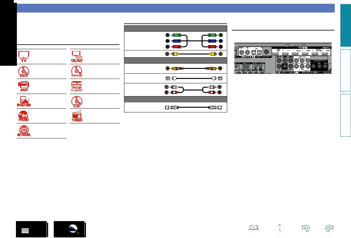
Connecting an HDMI-incompatible device
For high quality video and surround playback, it is recommended to use an HDMI cable to connect this unit to TV and other video devices (vpage 8 “Connecting an HDMI-compatible device”).
This section describes connections when your device does not support HDMI connections.
Connection methods for various devices
vpage 15 |
vpage 16 |
vpage 18 |
vpage 18 |
vpage 19 |
vpage 20 |
vpage 21 |
vpage 22 |
vpage 23 |
vpage 24 |
Cables used for connections
Video cable (sold separately) |
|
Component video |
|
cable |
|
Video cable |
|
Audio cable (sold separately) |
|
Coaxial digital cable |
|
Optical cable |
|
L |
L |
Audio cable |
|
R |
R |
Cable (sold separately) |
|
Ethernet cable |
|
vpage 27
Changing the source assigned to connectors
This unit can change the source that is assigned to the HDMI IN, DIGITAL AUDIO IN and COMPONENT VIDEO IN connectors.
Let us take a digital audio connection for Blu-ray Disc players for an example. The rear panel digital audio input connectors do not have the input connector indication for Blu-ray disc players (Blu-ray). However, DIGITAL AUDIO IN connectors have the “ASSIGNABLE” indication, which means that you can change the source assigned to these connectors. You can assign Blu-ray disc players to these connectors to use them for Blu-ray disc players. Select “Blu-ray” when switching functions on this unit to play back the source connected to these connectors.
nnHow to change the source assigned to connectors (vpage 125)
version Basic
version Advanced
Informations
14
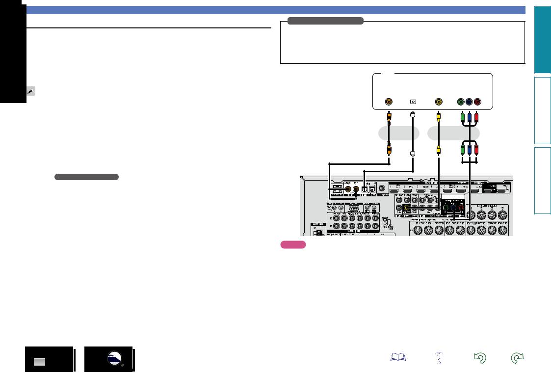
Connecting a TV
•This section describes how to connect when your TV does not support HDMI connections.
For instructions on HDMI connections, see “Connecting an HDMI-compatible device” (vpage 8).
•If the TV connected to this unit is equipped with an HDMI connector that supports ARC, digital audio signals from TV can be transmitted to this unit (vpage 9 “About ARC (Audio Return Channel) function”). The ARC function allows you to enjoy on this unit the audio from TV programs and HDMI devices directly connected to TV, without having to make a separate audio connection. For the ARC function, also see your TV’s manual.
listen to TV audio through this device, use the optical digital connection.
For video connections, see “Converting input video signals for output (Video conversion function)” (vpage 6).
nnAudio connection
The following methods are available for connecting to this unit. Use either of the methods to make a connection.
a DIGITAL AUDIO OPTICAL connector DIGITAL AUDIO COAXIAL connector z
When a multichannel audio (digital bit stream audio) is input, this unit decodes the audio to play back surround sound.
zzWhen making this type of connection, you must change the settings on this unit. (v Input connector setting )
nnVideo connection
The following methods are available for connecting to this unit. Use either of the methods to make a connection.
The numbers prefixed with connectors indicate the recommendation order. The smaller the number is, the higher playback quality is achieved.
a COMPONENT VIDEO OUT (MONITOR) connector
This makes an analog video connection. This connection method separates video signals into 3 signals for transmission based on color components, achieving the best quality video playback among analog video connections, with less signal degradation.
s VIDEO OUT (MONITOR) connector
This makes an analog video connection.
Connecting an HDMI-incompatible device
Input connector setting
When making the following connection, you must change the input connector settings.
aDIGITAL AUDIO COAXIAL connector
When connecting to connectors marked as 1, change “CBL/SAT” to “TV AUDIO”.
For how to change, see “Input Assign” (vpage 125).
TV
|
AUDIO |
|
|
|
|
|
|
|
VIDEO |
|
|
||
|
|
|
|
|
|
|
|
|
|||||
|
|
|
|
|
|
|
|
|
|
|
|
|
|
|
|
|
|
|
|
|
|
|
|
|
|
|
|
|
|
|
|
|
|
|
|
|
|
|
|||
COAXIAL |
|
|
OPTICAL |
|
VIDEO |
|
|
COMPONENT VIDEO |
|
||||
OUT |
|
|
OUT |
|
IN |
|
|
|
IN |
|
|||
|
|
|
|
|
|
|
|
|
|
|
Y PB PR |
|
|
|
|
|
|
|
|
|
|
|
|
|
|
|
|
|
|
|
|
|
|
|
|
|
|
|
|
|
|
a a |
s a |
or |
or |
NOTE
•The menu screen is only displayed on TV connected to this unit via HDMI. If your TV is connected to this unit via other video output connectors, perform menu operations while seeing the display on this unit.
•If you do not connect this unit to your TV via HDMI, do not make HDMI connections for video inputs from other video devices, either. For details see “Converting input video signals for output (Video conversion function)” (vpage 6).
version Basic
version Advanced
Informations
15
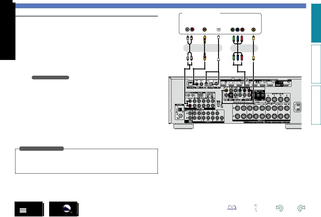
Connecting an HDMI-incompatible device
Connecting a set-top box (Satellite tuner/cable TV) |
|
Satellite tuner/Cable TV |
This section describes how to connect when your satellite tuner or cable TV does not support HDMI connections.
For instructions on HDMI connections, see “Connecting an HDMI-compatible device” (vpage 8).
nnAudio connection
The following methods are available for connecting to this unit. Use either of the methods to make a connection.
The numbers prefixed with connectors indicate the recommendation order. The smaller the number is, the higher playback quality is achieved.
a DIGITAL AUDIO COAXIAL connector DIGITAL AUDIO OPTICAL connector z
When a multichannel audio (digital bit stream audio) is input, this unit decodes the audio to play back surround sound.
zzWhen making this type of connection, you must change the settings on this unit. (v Input connector setting )
s AUDIO IN (CBL/SAT) connector
This makes an analog audio connection. This type of connection converts digital audio to analog audio, so the output audio may be degraded compared to connections a.
nnVideo connection
The following methods are available for connecting to this unit. Use either of the methods to make a connection.
The numbers prefixed with connectors indicate the recommendation order. The smaller the number is, the higher playback quality is achieved.
a COMPONENT VIDEO IN (CBL/SAT) connector
This makes an analog video connection. This connection method separates video signals into 3 signals for transmission based on color components, achieving the best quality video playback among analog video connections, with less signal degradation.
s VIDEO IN (CBL/SAT) connector
This makes an analog video connection.
Input connector setting
When making the following connection, you must change the input connector settings.
aDIGITAL AUDIO OPTICAL connector
When connecting to connectors marked as 1, change “TV AUDIO” to “CBL/SAT”.
For how to change, see “Input Assign” (vpage 125).
|
|
|
AUDIO |
|
|
|
|
|
|
|
VIDEO |
|
|
|
|
|
|
|
|
|
|
|
|
|
|
||
|
|
|
|
|
|
|
|
|
|
|
|
|
|
|
|
|
|
|
|
|
|
|
|
|
|
|
|
|
|
|
|
|
|
|
|
|
|
|
|||
AUDIO |
|
COAXIAL |
|
OPTICAL |
|
COMPONENT VIDEO |
|
VIDEO |
|||||
OUT |
|
|
OUT |
|
OUT |
|
OUT |
|
OUT |
||||
L R |
|
|
|
|
|
|
|
|
|
Y PB PR |
|
|
|
|
|
|
|
|
|
|
|
|
|
|
|
|
|
|
|
|
|
|
|
|
|
|
|
|
|
|
|
s L R |
a |
a |
a |
s |
|
or |
or |
|
or |
L R |
|
|
|
|
version Basic
version Advanced
Informations
16
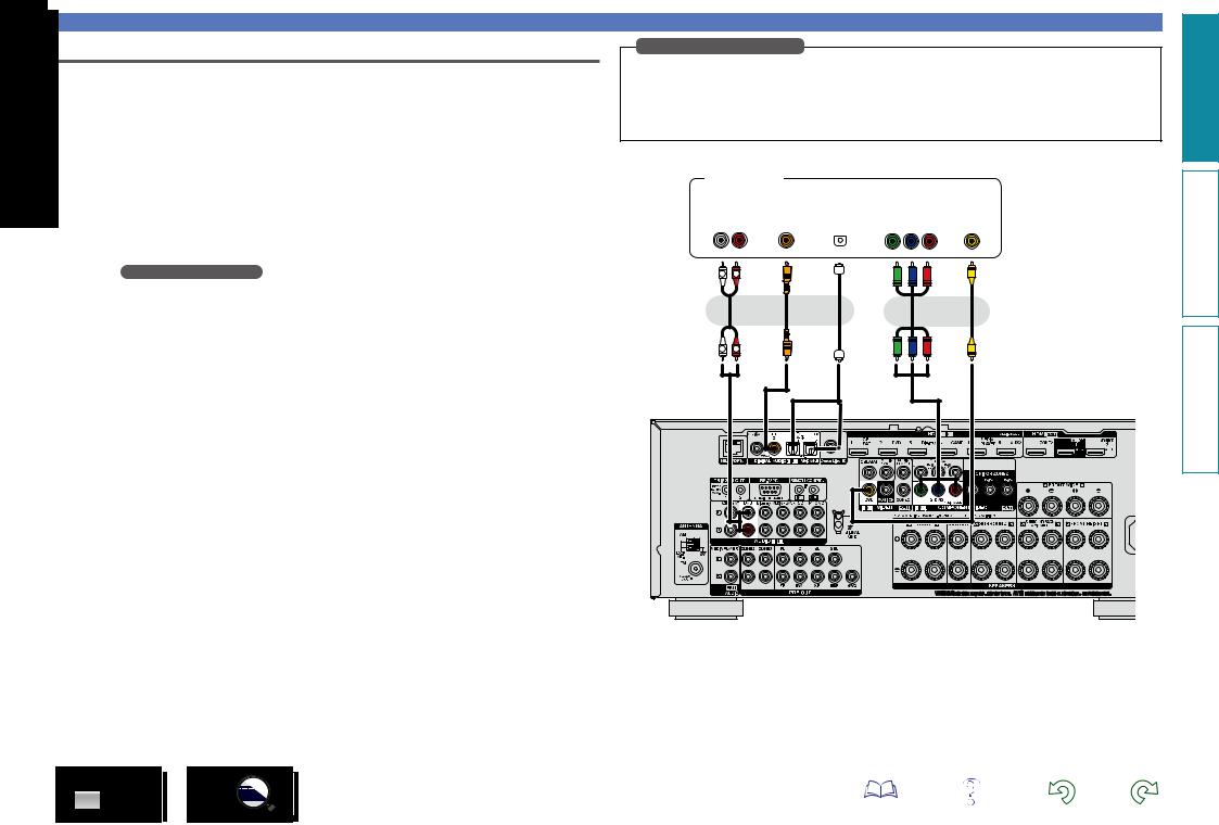
Connecting a DVD player
This section describes how to connect when your DVD player does not support HDMI connections.
For instructions on HDMI connections, see “Connecting an HDMI-compatible device” (vpage 8).
nnAudio connection
The following methods are available for connecting to this unit. Use either of the methods to make a connection.
The numbers prefixed with connectors indicate the recommendation order. The smaller the number is, the higher playback quality is achieved.
Connecting an HDMI-incompatible device
Input connector setting
When making the following connection, you must change the input connector settings.
aDIGITAL AUDIO OPTICAL connector
When connecting to connectors marked as 1, change “TV AUDIO” to “DVD”.
For how to change, see “Input Assign” (vpage 125).
DVD player
a DIGITAL AUDIO COAXIAL connector DIGITAL AUDIO OPTICAL connector z
When a multichannel audio (digital bit stream audio) is input, this unit decodes the audio to play back surround sound.
zzWhen making this type of connection, you must change the settings on this unit. (v Input connector setting )
s AUDIO IN (DVD) connector
This makes an analog audio connection. This type of connection converts digital audio to analog audio, so the output audio may be degraded compared to connections a.
nnVideo connection
The following methods are available for connecting to this unit. Use either of the methods to make a connection.
The numbers prefixed with connectors indicate the recommendation order. The smaller the number is, the higher playback quality is achieved.
a COMPONENT VIDEO IN (DVD) connector
This makes an analog video connection. This connection method separates video signals into 3 signals for transmission based on color components, achieving the best quality video playback among analog video connections, with less signal degradation.
s VIDEO IN (DVD) connector
This makes an analog video connection.
|
|
|
AUDIO |
|
|
|
|
|
|
|
VIDEO |
|
|
|
|
|
|
|
|
|
|
|
|
|
|
||
|
|
|
|
|
|
|
|
|
|
|
|
|
|
|
|
|
|
|
|
|
|
|
|
|
|
|
|
AUDIO |
|
COAXIAL |
|
OPTICAL |
|
COMPONENT VIDEO |
|
VIDEO |
|||||
OUT |
|
|
OUT |
|
OUT |
|
OUT |
|
OUT |
||||
L R |
|
|
|
|
|
|
|
|
|
Y PB PR |
|
|
|
|
|
|
|
|
|
|
|
|
|
|
|
|
|
|
|
|
|
|
|
|
|
|
|
|
|
|
|
s L R |
a |
a |
a |
s |
|
or |
or |
|
or |
L R |
|
|
|
|
version Basic
version Advanced
Informations
17
Connecting a Blu-ray Disc player
This section describes how to connect when your Blu-ray disc player does not support HDMI connections. For instructions on HDMI connections, see “Connecting an HDMI-compatible device” (vpage 8).
nnAudio connection
The following methods are available for connecting to this unit. Use either of the methods to make a connection.
The numbers prefixed with connectors indicate the recommendation order. The smaller the number is, the higher playback quality is achieved.
a DIGITAL AUDIO COAXIAL connector
DIGITAL AUDIO OPTICAL connector
When a multichannel audio (digital bit stream audio) is input, this unit decodes the audio to play back surround sound. However, digital bit stream audio signals for HD audios from Blu-ray disc players (such as Dolby Digital Plus and dts-HD) can not be transmitted.
When making this type of connection, you must change the settings on this unit. (v Input connector setting )
s AUDIO IN (Blu-ray) connector
This makes an analog audio connection. This type of connection converts digital audio to analog audio, so the output audio may be degraded compared to connections a.
nnVideo connection
The following methods are available for connecting to this unit.
a COMPONENT VIDEO IN connector
This makes an analog video connection. This connection method separates video signals into 3 signals for transmission based on color components, achieving the best quality video playback among analog video connections, with less signal degradation.
When making this type of connection, you must change the settings on this unit. (v Input connector setting )
Input connector setting
When making the following connection, you must change the input connector settings.
aDIGITAL AUDIO COAXIAL connector
When connecting to connectors marked as 1, change “CBL/SAT” to “Blu-ray”.
DIGITAL AUDIO OPTICAL connector
When connecting to connectors marked as 1, change “TV AUDIO” to “Blu-ray”.
aCOMPONENT VIDEO IN connector
When connecting to connectors marked as 1, change “CBL/SAT” to “Blu-ray”.
For how to change, see “Input Assign” (vpage 125).
Connecting an HDMI-incompatible device
Blu-ray Disc player
|
|
|
AUDIO |
|
|
|
|
|
|
|
VIDEO |
|
|
|
|
|
|
|
|
|
|
|
|
||
|
|
|
|
|
|
|
|
|
|
|
|
|
|
|
|
|
|
|
|
|
|
|
|
|
|
|
|
|
|
|
|
|
|
|
||||
AUDIO |
|
COAXIAL |
|
OPTICAL |
|
COMPONENT VIDEO |
||||||
OUT |
|
|
OUT |
|
OUT |
|
|
OUT |
||||
L R |
|
|
|
|
|
|
|
|
|
Y PB PR |
||
|
|
|
|
|
|
|
|
|
|
|
|
|
|
|
|
|
|
|
|
|
|
|
|
|
|
s L 
 R a
R a a
a a
a 


|
or |
or |
L |
R |
|
When you want to play back HD Audio (Dolby TrueHD, DTS-HD, Dolby Digital Plus, DTS Express) and Multichannel PCM with this unit, use an HDMI connection (vpage 8 “Connecting an HDMI-compatible device”).
version Basic
version Advanced
Informations
18
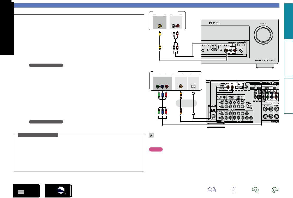
Connecting a digital camcorder
This section describes how to connect when your digital camcorder does not support HDMI connections.
For instructions on HDMI connections, see “Connecting an HDMI-compatible device” (vpage 8).
nnAudio connection
The following methods are available for connecting to this unit. Use either of the methods to make a connection.
The numbers prefixed with connectors indicate the recommendation order. The smaller the number is, the higher playback quality is achieved.
a DIGITAL AUDIO COAXIAL connector
DIGITAL AUDIO OPTICAL connector
When a multichannel audio (digital bit stream audio) is input, this unit decodes the audio to play back surround sound.
When making this type of connection, you must change the settings on this unit. (v Input connector setting )
s AUDIO IN (AUX1) connector
This makes an analog audio connection. This type of connection converts digital audio to analog audio, so the output audio may be degraded compared to connections a.
nnVideo connection
The following methods are available for connecting to this unit. Use either of the methods to make a connection.
The numbers prefixed with connectors indicate the recommendation order. The smaller the number is, the higher playback quality is achieved.
a COMPONENT VIDEO IN connector
This makes an analog video connection. This connection method separates video signals into 3 signals for transmission based on color components, achieving the best quality video playback among analog video connections, with less signal degradation.
When making this type of connection, you must change the settings on this unit. (v Input connector setting )
s VIDEO IN (AUX2) connector
This makes an analog video connection.
Input connector setting
When making the following connection, you must change the input connector settings.
aDIGITAL AUDIO COAXIAL connector
When connecting to connectors marked as 1, change “CBL/SAT” to “AUX2”.
DIGITAL AUDIO OPTICAL connector
When connecting to connectors marked as 1, change “TV AUDIO” to “AUX2”.
aCOMPONENT VIDEO IN connector
When connecting to connectors marked as 1, change “CBL/SAT” to “AUX2”.
For how to change, see “Input Assign” (vpage 125).
Connecting an HDMI-incompatible device
Digital camcorder
VIDEO |
AUDIO |
|
VIDEO |
AUDIO |
|
OUT |
OUT |
|
|
L |
R |
s |
s L |
R |
|
L |
R |
GFront panelH
|
INFO |
OPTION |
|
|
|
QUICK SELECT |
|
|
T STATUS |
|
|
DIMMER |
CBL/SAT |
Blu-ray |
GAME |
NETWORK |
|
|
ENTER |
|
VIDEO |
L - |
AUDIO |
- R |
SETUP MIC |
|
PHONES |
BACK |
SETUP |
|
|
|
|
|
|
|
|
|
|
AUX 1 |
|
|
|
|
Digital camcorder |
|
|
||
VIDEO |
AUDIO |
GRear panelH |
||
COMPONENT VIDEO |
COAXIAL |
OPTICAL |
||
|
||||
OUT |
OUT |
OUT |
|
|
Y PB PR |
|
|
|
|
a |
a |
a |
|
|
|
|
or |
|
|
You can enjoy games by connecting a game machine via the AUX1 input connector. In this case, select the input source to “AUX1”.
NOTE
When a non-standard video signal from a game machine or some other source is input, the video conversion function (vpage 6) might not operate. In this case, use the monitor output of the same connector as the input.
version Basic
version Advanced
Informations
19
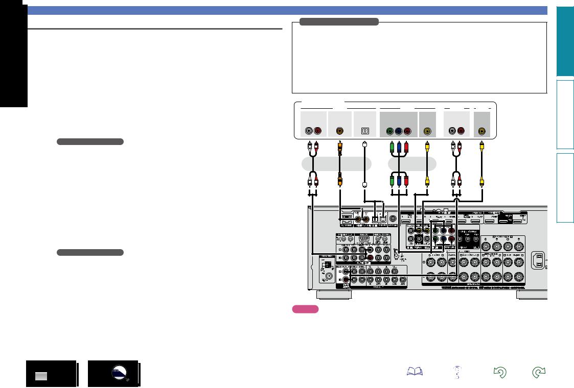
Connecting a media player
•This section describes how to connect when your media player does not support HDMI connections. For instructions on HDMI connections, see “Connecting an HDMI-compatible device” (vpage 8).
•When recording analog audio, use the analog connection.
•See “REC OUT mode” (vpage 99) for operating instructions.
nnAudio connection
The following methods are available for connecting to this unit. Use either of the methods to make a connection.
The numbers prefixed with connectors indicate the recommendation order. The smaller the number is, the higher playback quality is achieved.
a DIGITAL AUDIO COAXIAL connector
DIGITAL AUDIO OPTICAL connector
When a multichannel audio (digital bit stream audio) is input, this unit decodes the audio to play back surround sound.
When making this type of connection, you must change the settings on this unit. (v Input connector setting )
s AUDIO IN/OUT (MEDIA PLAYER) connector
This makes an analog audio connection. This type of connection converts digital audio to analog audio, so the output audio may be degraded compared to connections a.
nnVideo connection
The following methods are available for connecting to this unit. Use either of the methods to make a connection.
The numbers prefixed with connectors indicate the recommendation order. The smaller the number is, the higher playback quality is achieved.
a COMPONENT VIDEO IN connector
This makes an analog video connection. This connection method separates video signals into 3 signals for transmission based on color components, achieving the best quality video playback among analog video connections, with less signal degradation.
When making this type of connection, you must change the settings on this unit. (v Input connector setting )
s VIDEO IN/OUT (MEDIA PLAYER) connector
This makes an analog video connection.
Connecting an HDMI-incompatible device
Input connector setting
When making the following connection, you must change the input connector settings.
aDIGITAL AUDIO COAXIAL connector
When connecting to connectors marked as 1, change “CBL/SAT” to “MEDIA PLAYER”.
DIGITAL AUDIO OPTICAL connector
When connecting to connectors marked as 1, change “TV AUDIO” to “MEDIA PLAYER”.
aCOMPONENT VIDEO IN connector
When connecting to connectors marked as 1, change “CBL/SAT” to “MEDIA PLAYER”.
For how to change, see “Input Assign” (vpage 125).
Media player |
|
|
|
|
|
|
|
|
||
|
|
AUDIO |
|
|
VIDEO |
|
AUDIO |
VIDEO |
||
AUDIO |
COAXIAL |
OPTICAL |
COMPONENT VIDEO |
VIDEO |
AUDIO |
VIDEO |
||||
OUT |
OUT |
OUT |
|
OUT |
|
OUT |
|
IN |
IN |
|
L |
R |
|
|
|
Y PB |
PR |
|
L |
R |
|
s L R |
a a a |
|
|
s s L R |
s |
|||||
|
|
or |
or |
|
|
or |
|
|
|
|
L |
R |
|
|
|
|
|
|
L |
R |
|
version Basic
version Advanced
Informations
NOTE
To record video signals through this unit, use the video cable for connection between this unit and the player.
20
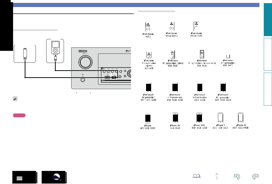
Connecting an iPod or USB memory device to the iPod/USB port
•You can enjoy music stored on an iPod or USB memory device.
•For operating instructions see “Playing an iPod” (vpage 39) or “Playing a USB memory device” (vpage 42).
Cables used for connections
To connect an iPod to this unit, use the USB cable supplied with the iPod.
iPod
USB memory device
or
Supported iPod models
• iPod classic
• iPod nano
ZONE 2 |
ZONE 3 |
INFO |
ON/OFF SOURCE SELECT ON/OFF SOURCE SELECT STATUS |
|
|
REC SOURCE |
|
EN |
|
PHONES |
BACK |
|
|
• iPod touch |
|
|
|
|
|
|
|
DENON does not guarantee that all USB memory devices will operate or receive power. When using a |
|
|||||
portable USB connection type HDD of the kind to which an AC adapter can be connected to supply power, |
|
|||||
• iPhone |
||||||
use the AC adapter. |
||||||
|
||||||
NOTE
•USB memory devices will not work via a USB hub.
•It is not possible to use this unit by connecting the unit’s iPod/USB port to a PC via a USB cable.
•Do not use an extension cable when connecting a USB memory device. This may cause radio interference with other devices.
•When connecting an iPhone to this unit, keep the iPhone at least 20 cm away from this unit. If the iPhone is kept closer to this unit and a telephone call is received by the iPhone, noise may be output from this device.
•If the iPod is connected using an iPod cable (commercially available) that is longer than 6.6 ft (2 m), sound may not be played correctly. In this case, use a genuine iPod cable, or a cable that is shorter than 3.3 ft (1 m).
21
Connecting an HDMI-incompatible device
version Basic
version Advanced
Informations
(as of April 2012)
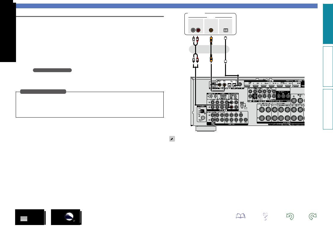
Connecting an HDMI-incompatible device
Connecting a CD player
You can enjoy CD sound.
nnAudio connection
The following methods are available for connecting to this unit. Use either of the methods to make a connection.
The numbers prefixed with connectors indicate the recommendation order. The smaller the number is, the higher playback quality is achieved.
a DIGITAL AUDIO COAXIAL connector z
DIGITAL AUDIO OPTICAL connector
When a multichannel audio (digital bit stream audio) is input, this unit decodes the audio to play back surround sound.
zzWhen making this type of connection, you must change the settings on this unit. (v Input connector setting )
s AUDIO IN (CD) connector
This makes an analog audio connection. This type of connection converts digital audio to analog audio, so the output audio may be degraded compared to connections a.
Input connector setting
When making the following connection, you must change the input connector settings.
aDIGITAL AUDIO COAXIAL connector
When connecting to connectors marked as 1, change “CBL/SAT” to “CD”.
For how to change, see “Input Assign” (vpage 125).
CD player
|
|
AUDIO |
|
AUDIO |
COAXIAL |
OPTICAL |
|
OUT |
OUT |
OUT |
|
L |
R |
|
|
s L |
R |
a |
a |
|
|
or |
or |
L |
R |
|
|
version Basic
version Advanced
Informations
When you want to play back HD Audio (Dolby TrueHD, DTS-HD, Dolby Digital Plus, DTS Express), DSD and Multi-channel PCM with this unit, use an HDMI connection (vpage 8 “Connecting an HDMIcompatible device”).
22
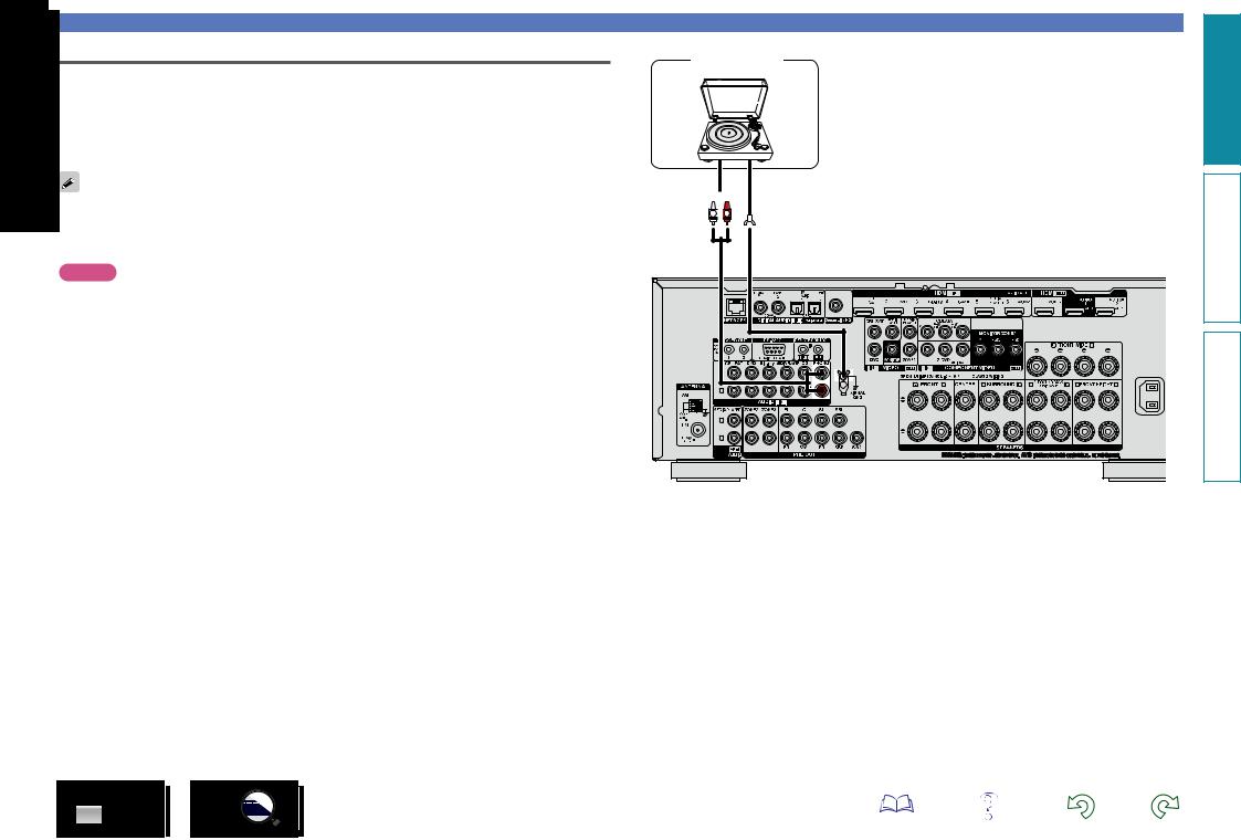
Connecting a record player
You can enjoy playing records.
nnAudio connection
The following methods are available for connecting to this unit.
AUDIO IN (PHONO) connector
This makes an analog audio connection.
•This unit is compatible with record players with an MM cartridge. When you connect to a record player with an MC cartridge, use a commercially available MC head amp or a step-up transformer.
•If you set this unit’s input source to “PHONO” and increase the volume without connecting the record player, there may be a “booming” noise from the speakers.
NOTE
The SIGNAL GND terminal of this unit is not a safety ground connection. Connect it to reduce noise when noise is excessive. Note that depending on the record player, connecting the ground line may have the reverse effect of increasing noise. In this case, it is not necessary to connect the ground line.
Turntable (MM cartridge)
AUDIO
OUT
L 
 R
R
GND |
Connecting an HDMI-incompatible device
version Basic
version Advanced
Informations
23
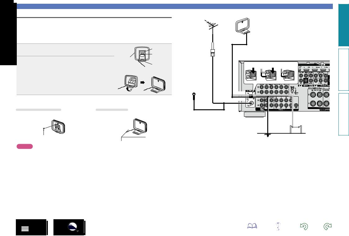
Connecting an HD Radio receiver
•By connecting a HD Radio antenna to this unit, you can receive HD Radio programs.
•HD Radio broadcasting currentry is available in the United States and select other countries.
•After connecting the antenna and receiving a broadcast signal (vpage 46 “Listening to HD Radio stations”), fix the antenna with tape in a position where the noise level becomes minimal.
nnAM loop antenna assembly
Put the stand section through the bottom of the |
|
Stand |
|
1 loop antenna from the rear and bend it forward. |
Loop |
Square |
|
|
|||
Insert the projecting part into the square hole in |
hole |
||
antenna |
|||
2 the stand. |
|
Projecting |
part
nnUsing the AM loop antenna |
|
Suspending on a wall |
Standing alone |
Suspend directly on a wall without assembling.
Nail, tack, etc.
NOTE
Use the procedure shown above to assemble.
•Do not connect two FM antennas simultaneously.
•Even if an external AM antenna is used, do not disconnect the AM loop antenna.
•Make sure the AM loop antenna lead terminals do not touch metal parts of the panel.
•If the signal has noise interference, connect the ground terminal (GND) to reduce noise.
•If you are unable to receive a good broadcast signal, we recommend installing an outdoor antenna. For details, inquire at the retail store where you purchased the unit.
Connecting an HDMI-incompatible device
Direction of broadcasting station
FM outdoor antenna
AM loop antenna (for HD Radio broadcasting, supplied)
•To prevent interference, install at least 3.3 ft/1 m away from the antenna connected to the this unit’s other AM tuner terminal.
75 Ω coaxial |
|
|
cable |
|
|
q |
w |
e |
White |
|
|
Black |
|
|
FM indoor antenna |
|
|
(for HD Radio |
|
|
broadcasting, supplied) |
|
|
|
Ground |
AM outdoor |
|
antenna |
version Basic
version Advanced
Informations
24
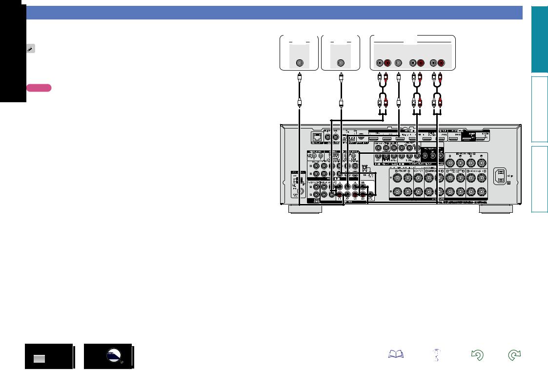
Connecting a external power amplifier
• You can use this unit as a pre-amp by connecting a commercially available power amp to the PRE OUT
. Adding a power amp to each of the channels provides an even greater sound presence. the terminal to use and connect the device.
•When using just one surround back speaker, connect it to the left channel (L) terminal.
•Use the volume control on the subwoofer to control subwoofer volume.
•If the subwoofer volume sounds low, use the volume control provided on the subwoofer to adjust the volume.
NOTE
When external power amplifier have been connected to PRE OUT terminals, do not connect the speakers to the speaker terminals.
Subwoofer |
Subwoofer |
|
(Primary) |
(Secondary) |
Power amplifier |
AUDIO |
AUDIO |
AUDIO |
SUB- |
SUB- |
FRONT |
CENTER SURROUND SURROUND |
||||
WOOFER |
WOOFER |
|
|
|
|
BACK |
|
1 |
2 |
L |
R |
L |
R |
L |
R |
|
|
||||||
|
|
L |
R |
L |
R |
L |
R |
|
|
L |
R |
L |
R |
L |
R |
25
version Basic
version Advanced
Informations

|
|
|
|
|
|
|
|
|
|
|
|
|
|
|
|
|
Connecting an external control device |
|
|
|
|
|
|
|
|
Basic |
|||
|
|
REMOTE CONTROL jacks |
|
RS-232C connector |
|
TRIGGER OUT jacks |
|
|||||||
|
|
devices connected to it by using a commercially available IR receiver. |
|
volume adjustment, and input source switching). |
to this unit. |
version |
||||||||
|
|
If this unit is installed in a location that is out of range of the signal |
When you connect an external control device, you can control this |
When a device with TRIGGER IN jack is connected, the connected |
|
|||||||||
|
|
from the remote control unit, you can still operate the unit and the |
unit with the external control device (such as power supply operation, |
device’s power on/standby can be controlled through linked operation |
|
|||||||||
|
|
You can also use it to remotely control ZONE2, ZONE3 (another room). |
|
|
|
|
The TRIGGER OUT jack outputs a maximum 12 V/150 mA electrical |
|
||||||
|
|
|
External serial controller |
|
|
|
||||||||
|
|
Infrared |
|
|
|
|
|
signal. |
|
|||||
|
|
Infrared |
|
|
|
|
|
|
|
|
|
|||
|
|
|
|
|
|
|
|
|
|
|
||||
|
|
retransmitter |
|
|
|
|
|
|
|
|
|
|||
|
|
sensor |
|
|
|
|
|
|
|
12 V/150 mA trigger-compatible device |
|
|||
|
|
|
|
|
|
|
|
|
|
|||||
|
|
|
|
|
|
|
|
|
|
|
||||
|
|
Device equipped with a |
|
|
versionAdvanced |
|
|
REMOTE CONTROL IN jack |
AUX |
Input |
Output |
OUT |
|
|
|
|
Informations |
|
|
|
|
|
|
|
|
|
|
|
|
|
|
|
Perform the operation below beforehand. |
NOTE |
|
|
|
|
|
|
|
|
|
|
|
|
|
|
|||
|
|
|
|
|
|
|
|
|
|
|
|
|
|
|
q Turn on the power of this unit. |
• Use the monaural mini-plug cable for connecting TRIGGER OUT |
|
|
|
|
|
|
|
|
|
|
|
|
|
|
|
||
|
|
|
|
|
|
|
|
|
|
|
|
|
|
|
w Turn off the power of this unit from the external controller. |
|
|
|
|
|
|
|
|
|
|
|
|
|
|
|
|
jacks. Do not use the stereo mini-plug cable. |
|
|
|
|
|
|
|
|
|
|
|
|
|
|
|
|
||
|
|
|
|
|
|
|
|
|
|
|
|
|
|
|
e Check that the unit is in the standby mode. |
|
|
|
|
|
|
|
|
|
|
|
|
|
|
|
|
• If the permissible trigger input level for the connected device is larger |
|
|
|
|
|
|
|
|
|
|
|
|
|
|
|
|
|
|
|
|
|
|
|
|
|
|
|
|
|
|
|
|
|
|
than 12 V/150 mA, or has shorted, the TRIGGER OUT jack cannot be |
|
|
|
|
|
|
|
|
|
|
|
|
|
|
|
|
used. In this case, turn off the power to the unit, and disconnect it. |
26
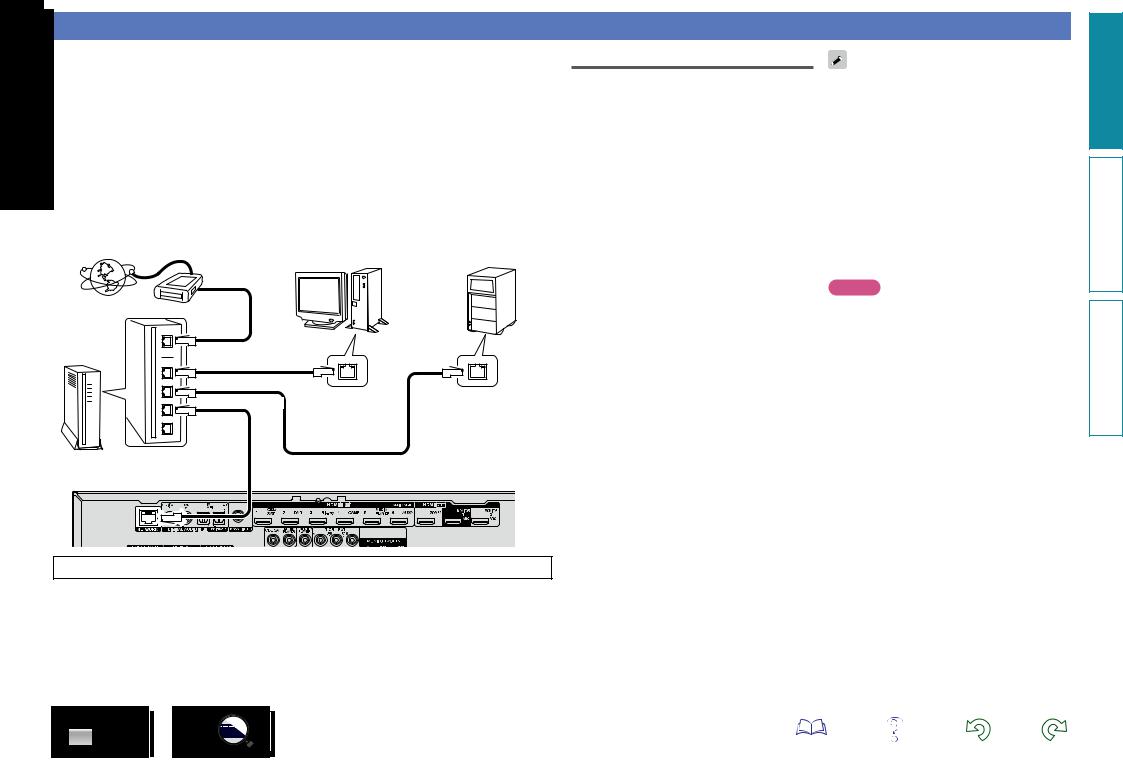
Connecting to a home network (LAN)
You can connect this unit to your home network (LAN) to perform various types of playbacks and operations as follows. Make network connections for this unit by carefully reading information on this page.
•Playback of network audio such as the Internet radio and music servers
•Playback of music from online services
•AirPlay
•Operations on this unit via the network
In addition, when an updated firmware becomes available for improving this unit, the update information is delivered from us to this unit over the network. You can then download the latest firmware.
For more information, on the menu, select “Update” (vpage 143).
Network settings are necessary. See “Network” on the menu (vpage 135) for more information on network setting.
|
NAS |
|
(Network Attached |
PC |
Storage) |
|
Modem
Internet
To WAN side |
To LAN port |
To LAN port |
LAN port/ |
LAN port/ |
Ethernet |
Ethernet |
connector |
connector |
Router
For connections to the Internet, contact an ISP (Internet Service Provider) or a computer shop.
Required system
nnBroadband internet connection
nnModem
Device that connects to the broadband circuit and conducts communications on the Internet. A type that is integrated with a router is also available.
nnRouter
When using this unit, we recommend you use a router equipped with the following functions:
•Built-in DHCP server
This function automatically assigns IP addresses on the LAN.
•Built-in 100BASE-TX switch
When connecting multiple devices, we recommend a switching hub with a speed of 100 Mbps or greater.
nnEthernet cable
(CAT-5 or greater recommended)
•Use only a shielded STP or ScTP LAN cable which is available at retailer.
• The normal shielded-type Ethernet cable is recommended. If a flat-type cable or unshielded-type cable is used, other devices could be affected by noise.
•If you have an Internet provider contract for a line on which network settings are made manually, make the settings at “Network” (vpage 135).
•With this unit, it is possible to use the DHCP and Auto IP functions to make the network settings automatically.
•When using this unit with the broadband router’s DHCP function enabled, this unit automatically performs the IP address setting and other settings.
When using this unit connected to a network with no DHCP function, make the settings for the IP address, etc., at “Network” (vpage 135).
•When setting manually, check the setting contents with the network administrator.
NOTE
•A contract with an ISP is required to connect to the Internet.
No additional contract is needed if you already have a broadband connection to the Internet.
•The types of routers that can be used depend on the ISP. Contact an ISP or a computer shop for details.
•DENON assumes no responsibility whatsoever for any communication errors or troubles resulting from customer’s network environment or connected devices.
•This unit is not compatible with PPPoE. A PPPoEcompatible router is required if you have a contract for a type of line set by PPPoE.
•Do not connect an NETWORK connector directly to the LAN port/ Ethernet connector on your computer.
•To listen to audio streaming, use a router that supports audio streaming.
version Basic
version Advanced
Informations
27
 Loading...