


JT360
6" (152mm) Jointer with Stand
Dégauchisseuse de 152 mm (6 po) avec support
Canteador de
152 mm (6 pulg) con base
Instruction Manual Manuel d’utilisation Manual de instrucciones
|
|
|
TO REDUCE THE RISK OF INJURY, |
|
|
||
|
|
|
USER MUST READ INSTRUCTION |
FRANÇAIS 27 |
ESPAÑOL 52 |
||
MANUAL BEFORE OPERATING PRODUCT. |
|||||||
|
|
|
|
|
PARA REDUCIR EL RIESGO |
|
|
|
|
|
|
|
|
|
|
|
|
|
|
|
DE LESIONES, EL USUARIO |
|
|
DEBE LEER EL MANUAL DE INSTRUCCIONES ANTES |
|
|
|||||
DE OPERAR EL PRODUCTO |
|
|
|||||
AFIN DE RÉDUIRE LE
RISQUE DE BLESSURES,
L’UTILISATEUR DOIT LIRE LE MODE D’EMPLOI WWW.DELTAMACHINERY.COM AVANT D’UTILISER LE PRODUIT.
(800) 223-7278 - US
(800) 463-3582 - CANADA
A23771 - 06-13-07
Copyright © 2007 Delta Machinery

TABLE OF CONTENTS
IMPORTANT SAFETY INSTRUCTIONS .................... |
2 |
TROUBLESHOOTING |
................................................24 |
SAFETY GUIDELINES - DEFINITIONS ..................... |
2 |
MAINTENANCE.......................................................... |
25 |
GENERAL SAFETY RULES ....................................... |
3 |
SERVICE............................................................... |
25 -26 |
ADDITIONAL SPECIFIC SAFETY RULES ................ |
4 |
ACCESSORIES.......................................................... |
26 |
FUNCTIONAL DESCRIPTION ................................... |
7 |
WARRANTY............................................................... |
26 |
CARTON CONTENTS ............................................... |
7 |
FRANÇAIS ................................................................. |
27 |
ASSEMBLY ................................................................. |
9 |
ESPAÑOL................................................................... |
52 |
OPERATION ............................................................... |
15 |
|
|
IMPORTANT SAFETY INSTRUCTIONS
 Read and understand all warnings and operating instructions before using any tool or equipment. When using tools or equipment, basic safety precautions should always be followed to reduce the risk of personal injury. Improper operation, maintenance or modification of tools or equipment could result in serious injury and property damage. There are certain applications for which
tools and equipment are designed. Delta Machinery strongly recommends that this product NOT be modified and/or used for any application other than for which it was designed.
If you have any questions relative to its application DO NOT use the product until you have written Delta Machinery and we have advised you. Contact us online at www.deltamachinery.com or by mail at Technical Service Manager, Delta Machinery, 4825 Highway 45 North, Jackson, TN 38305. In Canada,125 Mural St. Suite 300, Richmond Hill, ON, L4B 1M4)
Information regarding the safe and proper operation of this tool is available from the following sources:
•Power Tool Institute, 1300 Sumner Avenue, Cleveland, OH 44115-2851or online at www.powertoolinstitute.org
•National Safety Council, 1121 Spring Lake Drive, Itasca, IL 60143-3201
•American National Standards Institute, 25 West 43rd Street, 4 floor, New York, NY 10036 www.ansi.org - ANSI 01.1 Safety Requirements for Woodworking Machines
•U.S. Department of Labor regulations www.osha.gov
SAVE THESE INSTRUCTIONS!
SAFETY GUIDELINES - DEFINITIONS
It is important for you to read and understand this manual. The information it contains relates to protecting YOUR SAFETY and PREVENTING PROBLEMS. The symbols below are used to help you recognize this information.
Indicates an imminently hazardous situation which, if not avoided, will result in death or serious injury.
Indicates a potentially hazardous situation which, if not avoided, could result in death or serious injury.
Indicates a potentially hazardous situation which, if not avoided, may result in minor or moderate injury.
Used without the safety alert symbol indicates a potentially hazardous situation which, if not avoided, may result in property damage.
CALIFORNIA PROPOSITION 65
Some dust created by power sanding, sawing, grinding, drilling, and other construction activities contains chemicals known to cause cancer, birth defects or other reproductive harm. Some
examples of these chemicals are:
•lead from lead-based paints,
•crystalline silica from bricks and cement and other masonry products, and
•arsenic and chromium from chemically-treated lumber.
Your risk from these exposures varies, depending on how often you do this type of work. To reduce your exposure to these chemicals: work in a well ventilated area, and work with approved safety equipment, always wear NIOSH/OSHA approved, properly fitting face mask or respirator when using such tools.
2 - English

GENERAL SAFETY RULES
Failure to follow these rules may result in serious personal injury.
1.FOR YOUR OWN SAFETY, READ THE INSTRUCTION MANUAL BEFORE OPERATING THE MACHINE. Learning the machine’s application, limitations, and specific hazards will greatly minimize the possibility of accidents and injury.
2.WEAR EYE AND HEARING PROTECTION. ALWAYS USE SAFETY GLASSES. Everyday eyeglasses are NOT safety glasses. USE CERTIFIED SAFETY EQUIPMENT. Eye protection equipment should comply with ANSI Z87.1 standards. Hearing equipment should comply with ANSI S3.19 standards.
3.WEAR PROPER APPAREL. Do not wear loose clothing, gloves, neckties, rings, bracelets, or other jewelry which may get caught in moving parts. Nonslip protective footwear is recommended. Wear protective hair covering to contain long hair.
4.DO NOT USE THE MACHINE IN A DANGEROUS ENVIRONMENT. The use of power tools in damp or wet locations or in rain can cause shock or electrocution. Keep your work area well-lit to prevent tripping or placing arms, hands, and fingers in danger.
5.MAINTAIN ALL TOOLS AND MACHINES IN PEAK CONDITION. Keep tools sharp and clean for best and safest performance. Follow instructions for lubricating and changing accessories. Poorly maintained tools and machines can further damage the tool or machine and/or cause injury.
6.CHECK FOR DAMAGED PARTS. Before using the machine, check for any damaged parts. Check for alignment of moving parts, binding of moving parts, breakage of parts, and any other conditions that may affect its operation. A guard or any other part that is damaged should be properly repaired or replaced with Delta or factory authorized replacement parts. Damaged parts can cause further damage to the machine and/or injury.
7.KEEP THE WORK AREA CLEAN. Cluttered areas and benches invite accidents.
8.KEEP CHILDREN AND VISITORS AWAY. Your shop is a potentially dangerous environment. Children and visitors can be injured.
9.REDUCE THE RISK OF UNINTENTIONAL STARTING. Make sure that the switch is in the "OFF" position before plugging in the power cord. In the event of a power failure, move the switch to the "OFF" position. An accidental start-up can cause injury. Do not touch the plug’s metal prongs when unplugging or plugging in the cord.
10.USE THE GUARDS. Check to see that all guards are in place, secured, and working correctly to prevent injury.
11.REMOVE ADJUSTING KEYS AND WRENCHES BEFORE STARTING THE MACHINE. Tools, scrap pieces, and other debris can be thrown at high speed, causing injury.
12.USE THE RIGHT MACHINE. Don’t force a machine or an attachment to do a job for which it was not designed. Damage to the machine and/or injury may result.
13.USE RECOMMENDED ACCESSORIES. The use of accessories and attachments not recommended by Delta may cause damage to the machine or injury to the user.
14.USE THE PROPER EXTENSION CORD. Make sure your extension cord is in good condition. When using an extension cord, be sure to use one heavy enough to carry the current your product will draw. An undersized cord will cause a drop in line voltage, resulting in loss of power and overheating. See the Extension Cord Chart for the correct size depending on the cord length and nameplate ampere rating. If in doubt, use the next heavier gauge. The smaller the gauge number, the heavier the cord.
15.SECURE THE WORKPIECE. Use clamps or a vise to hold the workpiece when practical. Loss of control of a workpiece can cause injury.
16.FEED THE WORKPIECE AGAINST THE DIRECTION OF THE ROTATION OF THE BLADE, CUTTER, OR ABRASIVE SURFACE. Feeding it from the other direction will cause the workpiece to be thrown out at high speed.
17.DON’T FORCE THE WORKPIECE ON THE MACHINE.
Damage to the machine and/or injury may result.
18.DON’T OVERREACH. Loss of balance can make you fall into a working machine, causing injury.
19.NEVER STAND ON THE MACHINE. Injury could occur if the tool tips, or if you accidentally contact the cutting tool.
20.NEVER LEAVE THE MACHINE RUNNING UNATTENDED. TURN THE POWER OFF. Don’t leave the machine until it comes to a complete stop. A child or visitor could be injured.
21.TURN THE MACHINE "OFF", AND DISCONNECT THE MACHINE FROM THE POWER SOURCE before installing or removing accessories, changing cutters, adjusting or changing set-ups. When making repairs, be sure to lock the start switch in the "OFF" position. An accidental start-up can cause injury.
22.MAKE YOUR WORKSHOP CHILDPROOF WITH PADLOCKS, MASTER SWITCHES, OR BY REMOVING STARTER KEYS. The accidental start-up of a machine by a child or visitor could cause injury.
23. STAY ALERT, WATCH WHAT YOU ARE DOING, AND USE
COMMON SENSE. DO NOT USE THE MACHINE WHEN YOU ARE TIRED OR UNDER THE INFLUENCE OF DRUGS, ALCOHOL, OR MEDICATION. A moment of inattention while operating power tools may result in injury.
24.  USE OF THIS TOOL CAN GENERATE AND
DISBURSE DUST OR OTHER AIRBORNE PARTICLES, INCLUDING WOOD DUST, CRYSTALLINE SILICA DUST AND ASBESTOS DUST. Direct particles away from face and body. Always operate tool in well ventilated area and provide for proper dust removal. Use dust collection system wherever possible. Exposure to the dust may cause serious and permanent respiratory or other injury, including silicosis (a serious lung disease), cancer, and death. Avoid breathing the dust, and avoid prolonged contact with dust. Allowing dust to get into your mouth or eyes, or lay on your skin may promote absorption of harmful material. Always use properly fitting NIOSH/OSHA approved respiratory protection appropriate for the dust exposure, and wash exposed areas with soap and water.
3 - English

ADDITIONAL SPECIFIC SAFETY RULES
Failure to follow these rules may result in serious personal injury.
1. DO NOT OPERATE THIS MACHINE until it is completely assembled and installed according to the instructions. A machine incorrectly assembled can cause serious injury.
2.  OBTAIN ADVICE from your supervisor, instructor, or another qualified person if you are not thoroughly familiar with the operation of this machine. Knowledge is safety.
3. FOLLOW ALL WIRING CODES and recommended electrical connections to prevent shock or electrocution.
4.KEEP KNIVES SHARP and free from rust and pitch. Dull or rusted knives work harder and can cause kickback.
5.TIGHTEN THE INFEED/OUTFEED TABLES before starting the machine. Loss of control of the workpiece can cause serious injury.
6.PROPERLY SECURE THE BLADES IN THE CUTTERHEAD before turning the power "ON". Loose blades may be thrown out at high speeds.
7.NEVER TURN THE MACHINE "ON" before clearing the table of all objects (tools, scraps of wood, etc.). Flying debris can cause serious injury.
8.NEVER TURN THE MACHINE "ON" with the workpiece contacting the cutterhead. Kickback can occur.
9.AVOID AWKWARD OPERATIONS AND HAND POSITIONS. A sudden slip could cause a hand to move into the cutterhead.
10.KEEP ARMS, HANDS, AND FINGERS away from the cutterhead to prevent severe injury.
11.NEVER MAKE CUTS deeper than 1/8" (3.2mm) to prevent kickback.
12.NEVER JOINT OR PLANE A WORKPIECE that is shorter than 10" (254mm), narrower than 3/4" (19.0MM), or less than 1/2" (12.7mm) thick. Jointing smaller workpieces can place your hand in the cutterhead causing severe injury.
13.USE HOLD-DOWN/PUSH BLOCKS for jointing or planing any workpiece lower than the fence. Jointing or planing small workpieces can result in kickback and severe injury.
14.HOLD THE WORKPIECE FIRMLY against the table and fence. Loss of control of the workpiece can cause kickback and result in serious injury.
15.NEVER PERFORM "FREE-HAND" OPERATIONS.
Use the fence to position and guide the workpiece. Loss of control of the workpiece can cause serious injury.
16.DO NOT attempt to perform an abnormal or little-used operation without study and the use of adequate hold-down/push blocks, jigs, fixtures, stops, etc.
17.DO NOT FEED A WORKPIECE into the outfeed end of the machine.The workpiece will be thrown out of the opposite end at high speeds.
18.DO NOT FEED A WORKPIECE that is warped, contains knots, or is embedded with foreign objects (nails, staples, etc.) to prevent kickback.
19.MAINTAIN THE PROPER RELATIONSHIP OF INFEED AND OUTFEED TABLE SURFACES and cutterhead knife path. Loss of control of the workpiece can cause serious injury.
20.PROPERLY SUPPORT LONG OR WIDE WORKPIECES. Loss of control of the workpiece can cause injury.
21.NEVER PERFORM LAYOUT, ASSEMBLY, OR SETUP WORK on the table/work area when the machine is running. A sudden slip could cause a hand to move into the cutterhead. Severe injury can result.
22.TURN THE MACHINE "OFF", disconnect the machine from the power source, and clean the table/work area before leaving the machine. LOCK THE SWITCH IN THE "OFF" POSITION to prevent unauthorized use. Someone else might accidentally start the machine and cause injury to themselves.
23.ADDITIONAL INFORMATION regarding the safe and proper operation of power tools (i.e. a safety video) is available from the Power Tool Institute, 1300 Sumner Avenue, Cleveland, OH 44115-2851 (www. powertoolinstitute.com). Information is also available from the National Safety Council, 1121 Spring Lake Drive, Itasca, IL 60143-3201. Please refer to the American National Standards Institute ANSI 01.1 Safety Requirements for Woodworking Machines and the U.S. Department of Labor OSHA 1910.213 Regulations.
SAVE THESE INSTRUCTIONS.
Refer to them often and use them to instruct others.
4 - English
POWER CONNECTIONS
A separate electrical circuit should be used for your machines. This circuit should not be less than #12 wire and should be protected with a 20 Amp time lag fuse. If an extension cord is used, use only 3-wire extension cords which have 3-prong grounding type plugs and matching receptacle which will accept the machine’s plug. Before connecting the machine to the power line, make sure the switch (s) is in the "OFF" position and be sure that the electric current is of the same characteristics as indicated on the machine. All line connections should make good contact. Running on low voltage will damage the machine.
 Do not expose the machine to rain or operate the machine in damp locations.
MOTOR SPECIFICATIONS
Your machine is wired for 120/240 volts, 60 HZ alternating current. Before connecting the machine to the power source, make sure the switch is in the "OFF" position.
GROUNDING INSTRUCTIONS
 This machine must be grounded while in use to protect the operator from electric shock.
1.All grounded, cord-connected machines:
In the event of a malfunction or breakdown, grounding provides a path of least resistance for electric current to reduce the risk of electric shock. This machine is equipped with an electric cord having an equipment-grounding conductor and a grounding plug. The plug must be plugged into a matching outlet that is properly installed and grounded in accordance with all local codes and ordinances.
Do not modify the plug provided - if it will not fit the outlet, have the proper outlet installed by a qualified electrician.
Improper connection of the equipment-grounding conductor can result in risk of electric shock. The conductor with insulation having an outer surface that is green with or without yellow stripes is the equipment-grounding conductor. If repair or replacement of the electric cord or plug is necessary, do not connect the equipmentgrounding conductor to a live terminal.
Check with a qualified electrician or service personnel if the grounding instructions are not completely understood, or if in doubt as to whether the machine is properly grounded.
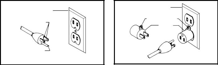
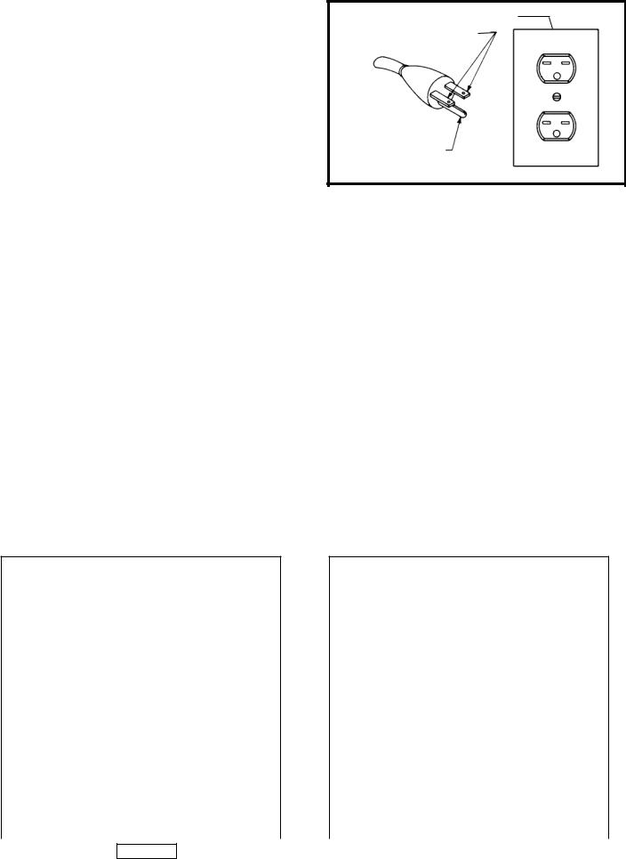
Use only 3-wire extension cords that have 3-prong grounding type plugs and matching 3-conductor receptacles that accept the machine’s plug, as shown in Fig. A.
Repair or replace damaged or worn cord immediately.
2.Grounded, cord-connected machines intended for use on a supply circuit having a nominal rating less than 150 volts:
If the machine is intended for use on a circuit that has an outlet that looks like the one illustrated in Fig. A, the machine will have a grounding plug that looks like the plug illustrated in Fig. A. A temporary adapter, which looks like the adapter illustrated in Fig. B, may be used to connect this plug to a matching 2-conductor receptacle as shown in Fig. B if a properly grounded outlet is not available. The temporary adapter should be used only until a properly grounded outlet can be installed by a qualified electrician. The green-colored rigid ear, lug, and the like, extending from the adapter must be connected to a permanent ground such as a properly grounded outlet box. Whenever the adapter is used, it must be held in place with a metal screw.
NOTE: In Canada, the use of a temporary adapter is not permitted by the Canadian Electric Code.
 In all cases, make certain that the receptacle in question is properly grounded. If you are not sure, have a qualified electrician check the receptacle.
Fig. A |
|
|
|
|
|
|
Fig. B |
GROUNDED OUTLET BOX |
|||
|
GROUNDED OUTLET BOX |
||||
|
|
|
|
|
|
|
CURRENT |
|
GROUNDING MEANS |
||
|
|
|
|
|
|
|
CARRYING |
|
|
|
|
|
|
|
ADAPTER |
|
|
|
PRONGS |
|
|
|
|
|
|
|
|
|
|
GROUNDING BLADE
IS LONGEST OF THE 3 BLADES
5 - English
3. 240 VOLT SINGLE PHASE OPERATION
The motor supplied with your machine is a dual voltage, 120/240 volt motor. It is shipped ready- to-run for 120 volt operation. However, it can be converted for 240 volt operation.
A qualified electrician should do the conversion, or the machine can be taken to an Authorized Delta Service Center. When completed, the machine must conform to the National Electric Code and all local codes and ordinances.
The machine is converted by re-wiring the motor for 240 volts, installing a 240 volt plug on the power supply cord and replacing the switch with one that is rated for 240 volt operation. (Delta P/N 438-01-017- 0141 needed for 240 volt operation.)
Be sure the 240 volt plug is only used in an outlet having the same configuration as the plug illustrated in Fig. C. No adapter should be used with the 240 volt plug.
 In all cases, make certain that the receptacle in question is properly grounded. If you are not sure, have a qualified electrician check the receptacle.
Fig. C |
GROUNDED OUTLET BOX |
CURRENT
CARRYING
PRONGS
GROUNDING BLADE
IS LONGEST OF THE 3 BLADES
EXTENSION CORDS
 Use proper extension cords. Make sure your extension cord is in good condition and is a 3- wire extension cord which has a 3-prong grounding type plug and matching receptacle which will accept the machine’s plug. When using an extension cord, be sure to use one heavy enough to carry the current of the machine. An undersized cord will cause a drop in line voltage, resulting in loss of power and overheating. Fig. D- 1 or D-2, shows the correct gauge to use depending on the cord length. If in doubt, use the next heavier gauge. The smaller the gauge number, the heavier the cord.
MINIMUM GAUGE EXTENSION CORD
RECOMMENDED SIZES FOR USE WITH STATIONARY ELECTRIC MACHINES
|
|
Total |
|
Ampere |
|
Length of |
|
|
Cord in |
Gauge of Extension |
|
|
|
||
Rating |
Volts |
Feet |
Cord |
0-6 |
120 |
up to 25 |
18 AWG |
0-6 |
120 |
25-50 |
16 AWG |
0-6 |
120 |
50-100 |
16 AWG |
0-6 |
120 |
100-150 |
14 AWG |
6-10 |
120 |
up to 25 |
18 AWG |
6-10 |
120 |
25-50 |
16 AWG |
6-10 |
120 |
50-100 |
14 AWG |
6-10 |
120 |
100-150 |
12 AWG |
10-12 |
120 |
up to 25 |
16 AWG |
10-12 |
120 |
25-50 |
16 AWG |
10-12 |
120 |
50-100 |
14 AWG |
10-12 |
120 |
100-150 |
12 AWG |
12-16 |
120 |
up to 25 |
14 AWG |
12-16 |
120 |
25-50 |
12 AWG |
12-16 |
120 |
GREATER THAN 50 FEET NOT RECOMMENDED |
|
Fig. D-1
MINIMUM GAUGE EXTENSION CORD
RECOMMENDED SIZES FOR USE WITH STATIONARY ELECTRIC MACHINES
|
|
Total |
|
|
|
Ampere |
|
Length of |
|
|
|
|
Cord in |
Gauge of Extension |
|||
|
|
||||
Rating |
Volts |
Feet |
|
Cord |
|
0-6 |
240 |
up to 50 |
|
18 AWG |
|
0-6 |
240 |
50-100 |
|
16 AWG |
|
0-6 |
240 |
100-200 |
|
16 AWG |
|
0-6 |
240 |
200-300 |
|
14 AWG |
|
6-10 |
240 |
up to 50 |
|
18 AWG |
|
6-10 |
240 |
50-100 |
|
16 AWG |
|
6-10 |
240 |
100-200 |
|
14 AWG |
|
6-10 |
240 |
200-300 |
|
12 AWG |
|
10-12 |
240 |
up to 50 |
|
16 AWG |
|
10-12 |
240 |
50-100 |
|
16 AWG |
|
10-12 |
240 |
100-200 |
|
14 AWG |
|
10-12 |
240 |
200-300 |
|
12 AWG |
|
12-16 |
240 |
up to 50 |
|
14 AWG |
|
12-16 |
240 |
50-100 |
|
12 AWG |
|
12-16 |
240 |
GREATER THAN 50 FEET NOT RECOMMENDED |
|||
|
|
|
|
|
|
|
|
|
Fig. D-2 |
|
|
|
|
|
|
|
|
6 - English

FUNCTIONAL DESCRIPTION
FOREWORD
The Delta JT360 6" (152mm) Jointer with Stand is designed with a cutting capacity of 6" (152mm) width, 1/2" (13mm) depth and rabbeting 1/2" (13mm). Unit includes; heavy-duty 3/4 hp, 115/230 volt induction motor, stand, dust chute, center-mounted fence, three-knife cutterhead, cutterhead guard, and push blocks
NOTICE: The manual cover illustrates the current production model. all other illustrations are representative only and may not depict the actual color, labeling or accessories and may be intended to illustrate technique only.
CARTON CONTENTS
Fig. 4
24
22
23
2
11
12 13
14
16
 18
18
15 |
17 |
|
19
21
20
1
 3
3
 4
4
5 |
6 |
|

 7
7
8
10
9
|
|
|
|
|
|
|
|
|
|
|
28 |
33 |
|
|
Fig. 4A |
26 |
|
|||
25 |
|
|
|
29 |
34 |
|
|
|
|
|
|||
|
|
|
|
|
||
|
|
|
|
30 |
35 |
|
|
|
|
|
31 |
36 |
|
|
|
|
|
|
37 |
|
|
|
|
32 |
|
|
|
27 |
|
|
Fig. 4B |
|
||
|
|
|
|
|
|
|
|
|
|
|
|
|
|
7 - English
JOINTER PARTS
Fig. 4
1.Motor and Switch
2.Jointer
3.Motor Pulley
4.V-Belt
5.Two Top End Braces for Stand (11-3/4")
6.Two Top Side Braces for Stand (15-3/4")
7.Two Lower Side Braces for Stand (20-1/2")
8.Two Lower End Braces for Stand (16-1/2")
9.Four Legs for Stand
10.Four Feet for Stand Legs
11.Cutterhead Guard
12.Fence Locking Handle
13.Fence Tilting Handle
14.Dust Chute
15.Dust Chute Cover
16.6mm Allen Wrench
17.4mm Allen Wrench
18.3mm Allen Wrench
19.2.5mm Allen Wrench
20.12x14mm Open End Wrench
21.8x10mm Open End Wrench
22.Rear Cutterhead Guard
23.Fence
24.Motor Pulley and Belt Guard
Fig. 4A
25.Dust Collector Adapter
26.Push Blocks
27.Infeed Table Adjustment Rod, Handle, and Nut
Fig. 4B
28.Special Studs (3)
29.5/16-18x1¼" Carriage Bolts (4)
30.5/16-18x3/4" Carriage Bolts (36)
31.M6x1x10mm Cheese Head Screws (4)
32.Wing Screws (2)
33.5/16-18Hex Nuts (40)
34.5/16 Flat Washers (36)
35.M10.2 Lockwashers for Special Studs (3)
36.M8.4 Flat Washer
37.M6.1 Lockwashers (4)
UNPACKING AND CLEANING
Carefully unpack the machine and all loose items from the shipping container(s). Remove the rust-preventative oil from unpainted surfaces using a soft cloth moistened with mineral spirits, paint thinner or denatured alcohol.
 Jointer weight is approximately 175 lbs. Care must be taken when lifting jointer onto stand. A minimum of two people will be required to lift the machine.
 Do not use highly volatile solvents such as gasoline, naphtha, acetone or lacquer thinner for cleaning your machine.
After cleaning, cover the unpainted surfaces with a good quality household floor paste wax.
8 - English
ASSEMBLY
 For your own safety, do not connect the machine to the power source until the machine is completely assembled and you read and understand the entire instruction manual.
ASSEMBLY TOOLS REQUIRED
*6mm Allen Wrench
*4mm Allen Wrench
*3mm Allen Wrench
*2.5mm Allen Wrench
*12x14mm Open End Wrench
*8x10mm Open End Wrench (All are supplied.)
ASSEMBLY TIME ESTIMATE - 2-3 hours
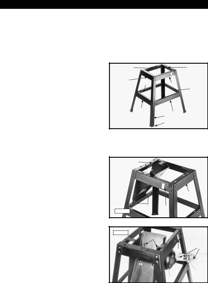
STAND
1.Assemble stand as shown in Fig. 5 using parts shown in Fig. 4. The parts for the stand (as shown in Fig. 4) are:
5.Two Top End Braces for Stand (11-3/4")
6.Two Top Side Braces for Stand (15-3/4")
7.Two Lower Side Braces for Stand (20-1/2")
8.Two Lower End Braces for Stand (16-1/2")
9.Four Legs for Stand
10.Four Feet for Stand Legs
To assemble, insert the 5/16-18x3/4" carriage head bolts through legs and braces then place the 5/16" flat washers on the bolts and secure with the 5/16-18 hex nuts. Only tighten nuts finger-tight at this time. IMPORTANT: The top lips of two upper end braces
(5) Fig. 5, must fit on top of the top lips of two upper side braces (6).
2.Assemble four rubber feet (10), to the bottom of each leg (9) as shown.
DUST CHUTE TO STAND
1.The front of the stand is indicated by switch opening
(B)Fig. 6, making the outfeed end of the stand (C) and the infeed end (A).
2.Assemble dust chute (E) Fig. 6, to outfeed end of stand (C) as shown. Align the four holes (D) Fig. 6, in the dust chute with the four holes in the stand. Insert a 5/16-18x3/4" carriage bolt through the hole in the dust chute and stand. Place a 5/16" flat washer onto the screw and thread a 5/16-18 hex nut onto the screw. Repeat this process for the three remaining holes in the dust chute and stand. Only tighten hex nuts fingertight at this time.
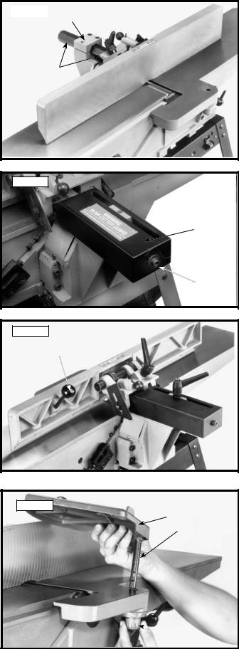
MOTOR AND SWITCH TO STAND
1.Assemble motor (B) Fig. 7, to the bottom of the dust chute. Align the four holes (F) Fig. 7, in the dust chute, with the four holes in the motor mounting plate. Insert a 5/16-18x1¼"carriage bolt through hole in dust chute and hole in motor mounting plate. Place a 5/16" flat washer on screw and secure with a 5/16-18 hex nut. Repeat this process for the three remaining holes. Do not completely tighten hex nuts at this time as the motor must be adjusted for proper alignment and belt tension later.
6 |
5 |
5
7
6
8
|
8 |
7 |
|
9 |
|
|
|
|
|
10 |
|
Fig. 5 |
|
C  D
D
D 
E  A
A
D B
Fig. 6
Fig. 7
F
A
D
C
F B
9 - English
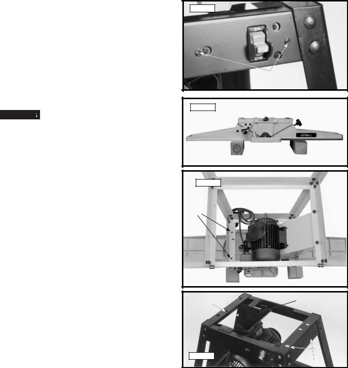
2.Remove M4x.7x10mm pan head screws, M4.1 flat washers and M4x.7 hex nuts from two holes (A) Fig. 7 in switch.
3.Insert switch assembly (C) Fig. 7 from the inside of the stand. Align the holes (A) in the switch with the holes in the stand (A) Fig. 8.
4.Place a M4.1 flat washer onto a M4x.7x10mm pan head screw. Insert screw through hole (A) in stand and switch. Thread a M4x.7 hex nut onto screw. Repeat this process for the remaining hole in stand and switch.
JOINTER TO STAND


 Jointer weight is approximately 175 lbs. Care must be taken when moving it. A minimum of two people will be required to lift the ma-
chine.
1.Turn jointer upside down so it lays flat. One way to do this is to place the jointer table onto two wooden 4x4s as shown in Fig. 9A.
2.Turn the stand upside down and align the threaded holes in the bottom of the jointer with the holes in the stand, two of which are shown at (A) Fig. 9B. The infeed end of the jointer is fastened to the stand through these two holes (A) Fig. 9B and (A) fig. 9C. The outfeed end of the jointer is fastened to the stand through hole (B) Fig. 9C.
Fig. 8
A
Fig. 9A
Fig. 9B
A
B C
Fig. 9C
A
10 - English
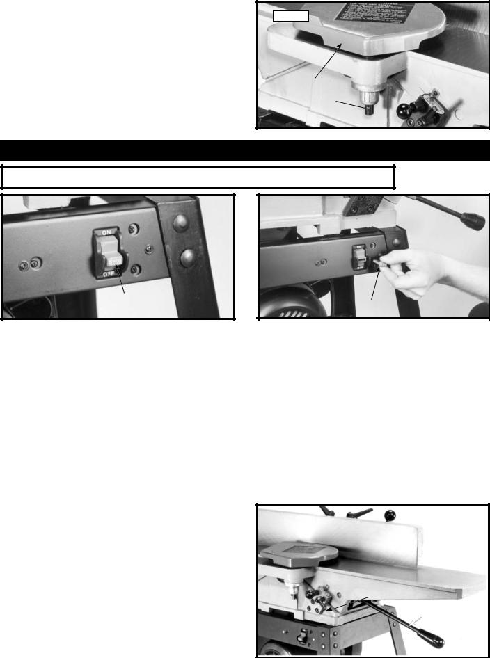
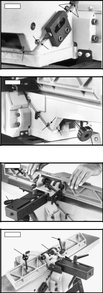
3.Using the supplied wrench (or a 14 mm socket wrench), fasten the jointer to the top of stand using the three M10.2 lockwashers and three special studs. Two of the special studs are shown at (D) Fig. 10. These are for the infeed end of the machine. The other special stud is shown at (D) Fig. 11, for the outfeed end of machine. Fully tighten the studs at this time.
4.Once the jointer is completely secured to stand, stand the machine upright. (Jointer is shown upright and fully assembled in Fig. 11A.)
5.Push downward on the top of jointer until the stand adjusts to the floor surface. Then using the supplied wrench, tighten all stand hardware.
Fig. 10
D
 D
D
Fig. 11
Fig.11A
11 - English

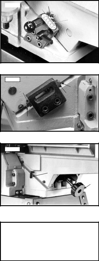
INFEED TABLE ADJUSTMENT HANDLE
1.Turn locknut (C) Fig. 12, clockwise on infeed table adjustment handle (B) as far as it will go.
2.Thread handle (B) Fig. 12, into block (D) which is located below infeed table (E).
3.Turn locknut (C) Fig. 13 clockwise to tighten against block (D).
Fig. 12 |
E |
 C
C
D
B
Fig. 13
C
D
DUST CHUTE COVER
1.Assemble dust chute cover (A) Fig. 14, to dust chute
(B)using two wing screws (C). IMPORTANT: Top of dust chute cover (A) must be inside top brace (D) of stand.
During operation, the dust chute cover
(A) must always be assembled as shown and should only be removed for cleaning.
DUST COLLECTOR ADAPTER
If the machine is to be connected to a dust collection system, a dust collector adapter with a 4" O.D. opening is supplied with the jointer. To assemble the adapter:
1.Remove two wing screws (C) Fig. 14, from dust chute cover (A).
2.Assemble adapter (E) Fig. 15, over dust chute (A). Align two holes in dust chute (A) with holes in adapter
(E) and fasten with two wing screws (C) which were removed in STEP 1.
Fig. 14
D 
A 
C 
B
C
A
C 
C
Fig. 15
E
12 - English
MOTOR PULLEY
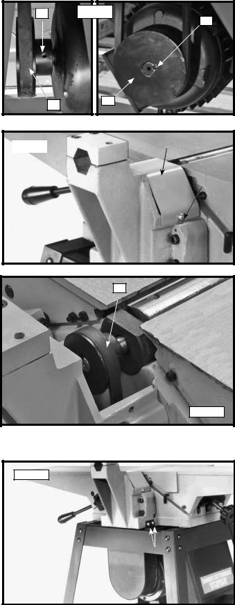
Assemble motor pulley (A) Fig. 16, to motor shaft, as shown. Make sure key (B) is inserted in the keyway of the motor pulley and shaft.
BELT, ALIGNING PULLEYS, AND
ADJUSTING BELT TENSION
1.Loosen two screws, one of which is shown at (A) Fig. 17, and remove cutterhead pulley guard (B)
2.Make certain the motor pulley (D) Fig. 16, is aligned with the cutterhead pulley (C) Fig. 18. If necessary, the motor pulley (D) can be moved in or out on the motor shaft to provide proper alignment. Then tighten two set screws, one shown at (C) Fig. 16.
3.Place the belt in groove of cutterhead pulley (C) Fig. 18, and motor pulley (D) Fig. 16. To place belt onto pulleys, lift up on motor. (Motor mounting hardware should still be loose.)
4.Correct belt tension is obtained when there is approximately 1" deflection at the centerspan of the belt using light finger pressure.
5.If an adjustment is required for belt tension, the motor can be raised or lowered to obtain the correct belt tension. Then tighten motor mounting hardware after tension is applied, making sure alignment of the pulleys is not disturbed.
6.Replace cutterhead pulley guard (B) Fig. 17, which was removed in STEP 1.
MOTOR PULLEY AND BELT GUARD
Assemble the motor pulley and belt guard (A) Fig. 19, to the jointer base using the four M6x1x10mm cheese head screws, two of which are shown at (B), and four M6.1 lockwashers.


 Make certain motor pulley is not contacting guard. If motor pulley is contacting the guard, adjust the motor pulley, see the section "BELT, ALIGNING
PULLEYS, AND ADJUSTING BELT TENSION."
|
Fig. 16 |
C |
B
D A
Fig. 17 |
B |
|
A
C
Fig. 18
Fig. 19
B
A 
13 - English
FENCE |
Fig. 20 |
B |
|
|
1. Insert hexagon rod (A) Fig. 20, of fence assembly into bracket (B) on jointer as shown.
A
2.Remove the M8x1.25x12mm long screw (D) and M8.4 flat washer (E) from the end of hexagon rod. Assemble rear cutterhead guard (C) Fig. 21, to end of hexagon rod using the M8x1.25x12mm long screw
(D) and M8.4 flat washer (E).
3.Thread fence locking handle assembly (F) Fig. 22, and M8.4 flat washer (G) into hole (Z) Fig. 21. Lock handle
(F)Fig. 22, is spring-loaded and can be repositioned by pulling out the handle and repositioning it onto the serrated nut located under the handle.
4.Thread fence tilting handle (H) Fig. 22, to threaded hole in back of fence as shown.
Fig. 21
 Z
Z
C
 E
E
D
Fig. 22
H
 F
F
 G
G
CUTTERHEAD GUARD
Fig. 23
1.Remove set screw (A) Fig. 23, from post (B) of cutterhead guard (C).
2.Assemble cutterhead guard (C) Fig. 23, to the jointer by inserting post (B) down through the hole in the infeed table. NOTE: A spring is supplied in knob assembly (D) that returns the guard (C) over the cutterhead after a cut has been made. Turn knob
(D)to tension spring before inserting post (B). Make certain the spring engages in the slot of the post. To adjust spring tension, remove the cutterhead guard (C) Fig. 23, and rotate knob (D) to the desired amount of tension. NOTE: THE CUTTERHEAD
GUARD MUST BE TENSIONED SO THAT IT WILL RETURN TO COVER THE CUTTERHEAD ONCE THE MATERIAL HAS PASSED.
C
B
 A
A
 D
D
14 - English
3.Replace set screw (A) Fig. 24, which was removed in
STEP 1.
4.Fig. 24, illustrates the cutterhead guard (C) assembled to the infeed table.
Fig. 24
C
A
B 
OPERATION
OPERATIONAL CONTROLS AND ADJUSTMENTS
Fig. 33 |
|
Fig. 34 |
A
B
STARTING AND STOPPING JOINTER
1.The on/off switch (A) Fig. 33 is located on the front of the jointer. To turn the machine "ON", move switch (A) up to the "ON" position.
2.To turn the machine "OFF", move the switch down to the "OFF" position.


 Make sure that the switch is in the "OFF" position before plugging in the power cord. In the event of a power failure, move the switch to the "OFF" position. An accidental start-up can cause injury.
LOCKING SWITCH IN THE "OFF" POSITION
IMPORTANT: When the tool is not in use, the switch should be locked in the "OFF" position to prevent unauthorized use. To lock the switch, grasp the switch toggle (A) Fig. 33 and pull it out of the switch. With the switch toggle (B) Fig. 34 removed, the switch will not operate. However, should the switch toggle be removed while the saw is running, the machine can be turned "OFF," but cannot be restarted without re-inserting the switch toggle (B).
INFEED TABLE ADJUSTMENTS |
|
Fig. 35 |
1.To raise or lower the infeed table, loosen table lockhandle (A) Fig. 35, move the table raising and lowering handle (B) up or down until the table is at the desired position and tighten table lockhandle (A).
A
B
15 - English
2. NOTE: When raising or lowering the infeed table a plunger located on other end of the index stop (C) Fig. 36, automatically stops the table at 1/8 inch depth of cut. To move the table past this point it is necessary to pull out index stop (C) and move the table up or down. IMPORTANT: Always make sure table lockhandle (A) is tightened before operation. The table lockhandle
(A) is spring-loaded and can be repositioned by pulling out the handle and repositioning it on the serrated nut located under the handle.
3.The depth of cut of the infeed table (position of table in relationship with the cutting circle) can be read with the pointer (D) Fig. 36, and scale (E). Maximum table depth adjustment with this 6" jointer is 1/2 inch.
INFEED TABLE POSITIVE STOPS
Positive stops are provided to limit the height and depth of the infeed table. To adjust the stops, loosen two locknuts
(F) and (G) Fig. 37, and turn the two adjusting screws (J) and (K) as required. Then retighten the locknuts (F) and
(G). A good suggestion is to set the upper positive stop
(J) for your finish or final cut. This means that you will be able to rapidly set the infeed table for a finish or final cut without checking the scale and pointer. Also the lower positive stop (K) can be set for the maximum 1/2" depth of cut or if you desire to limit the depth of cut, adjust the stop screw (K) accordingly.
OUTFEED TABLE ADJUSTMENTS
For most jointing operations the outfeed table must be level with the knives at their highest point of revolution. This means that the knives must be parallel to the outfeed table and project equally from the cutterhead. To move the outfeed table up or down, loosen lockscrew
(A) Fig. 38, and turn hand knob (B). When the outfeed table is level with the knives at their highest point of revolution, tighten lockscrew (A).
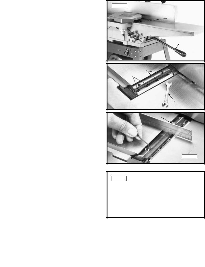
KNIFE AND OUTFEED TABLE ADJUSTMENTS
In order to do accurate work, the knives must be exactly level with the outfeed table. To check and adjust, proceed as follows:
1. Disconnect machine from power source.
2.Loosen lock lever (A) Fig. 40, and lower the infeed table by pushing handle (B) down. Remove cutterhead guard (C).
3.Place a straight edge on the outfeed table, extending over the cutterhead as shown in Fig. 39 and 42.
Fig. 36 |
D |
|
C |
|
E
 A
A
Fig. 37
J
F
G
K
Fig. 38
A
B
STEEL STRAIGHT EDGE |
|
OUT-FEED TABLE |
IN-FEED |
|
TABLE |
Fig. 39 |
CUTTER |
16 - English
4.CAREFULLY rotate the cutterhead by turning the belt by hand. The knives should just touch the straight edge.
Fig. 40
C
A
B
5.If the knife is high or low at either end, slightly turn the four screws (D) Fig. 41, in the knife locking bar clockwise to loosen using the wrench (E) supplied. Then adjust the height of the knife by turning the knife raising screws (F) Fig. 42, counterclockwise to lower and clockwise to raise the knife.
NOTE: If the knife is to be lowered it will be necessary to wear protective gloves and carefully push down on the knife with a piece of scrap wood after screws (F) have been turned.
6.Repeat these procedures for adjusting the remaining two knives.
7.If the knives are set too low, the result will be as shown in Fig. 43, and the finished surface will be curved.
8.If the knives are set too high, the work will be gouged at the end of the cut, as shown in Fig. 44.
9.As a final check, run a piece of work slowly over the knives for 6 to 8 inches. The wood should rest firmly on both tables as shown in Fig. 45, with no open spaces under the finished cut.
Fig. 41 |
D |
|
|
|
D |
E
F
F 
Fig. 42
Fig. 43
|
|
|
|
|
|
|
|
|
|
|
|
|
|
|
Fig. 45 |
|
|
|
Fig. 44 |
|
WORK |
WORK |
||||
|
|
|
|
|
|
|||
|
|
|
|
|
|
|
||
|
|
|
|
|
|
|
|
|
|
OUT-FEED |
IN-FEED TABLE |
|
|
OUT-FEED |
IN-FEED TABLE |
||
|
|
|
TABLE |
|||||
|
TABLE |
|
|
|
|
|||
|
|
|
|
|
|
|
||
KNIVES |
CUTTER |
|
KNIVES AT |
CUTTER |
||||
|
|
|||||||
SET TOO HIGH |
|
|
CORRECT HEIGHT |
|
||||
|
|
|
|
|
|
|
|
|
17 - English
ADJUSTING TABLE GIBS
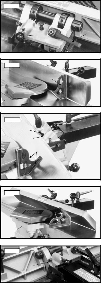
"Gibs" are provided to take up all play between the mating dovetail ways of the base and the infeed and outfeed tables. The "gib" for the infeed table is shown at (A) Fig. 46, and the "gib" for the outfeed table is shown at (B) Fig. 47. Proper "gib" adjustment is necessary for the correct functioning of the jointer. The "gibs" were adjusted at the factory and should require no further adjustment. If it becomes necessary to adjust the "gibs", proceed as follows:
1.To adjust the infeed or outfeed table "gibs," loosen three locknuts (F) Fig. 46, for the infeed table or two locknuts (G) Fig. 47, for the outfeed table. For the infeed table, make sure the table locking lever is loose. For the outfeed table, make sure the table locking screw (E) Fig. 47, is loose.
2.Tighten or loosen three gib adjustment screws (C) Fig. 46, as necessary for the infeed table or two gib adjustment screws (D) Fig. 47, as necessary for the outfeed table; starting with the lower screw first and as you proceed to the top screw, gently raise the outboard edge of the table that is being adjusted. This will offset any tendency for the table casting to "droop or sag" and permit the gib to be adjusted to a secure fit. After the gibs have been adjusted, tighten locknuts (F) Fig. 46, (G) Fig. 47, table locking screw
(E) Fig. 47, and infeed table locking lever.
IMPORTANT: Do not leave the adjusting screws too loose. It should take a little bit of effort to move the tables up or down. Jointers are finishing machines and you can’t expect proper accuracy or finish if the tables are not set properly.
FENCE OPERATION
The fence can be moved across the table and can tilt 45 degrees right or left at any position on the table as follows:
1.To move the fence across the table, loosen lock handle (A) Fig. 48, slide fence to the desired position on the table and tighten lockhandle (A). As the fence is moved across the table, the rear cutterhead guard
(B)covers and guards the cutterhead in back of the fence. NOTE: Lock handle (A) is spring-loaded and can be repositioned by pulling up on the handle and repositioning it on the serrated nut located underneath the hub of the handle.
2.To tilt the fence to the right or left loosen lock handle (C) Fig. 49, and pull out and turn plunger
(D)to release the positive stop. A tilting lever (E) is provided on the back of the fence to assist in tilting the fence. NOTE: Lock handle (C) is spring-loaded and can be repositioned by pulling out the handle and repositioning it on the serrated nut located underneath the hub of the handle.
3.Tilt the fence to the desired angle, in or out, and tighten lock handle (C) Fig. 49. IMPORTANT: When cutting bevels and the angle is small there is little difference whether the fence is tilted in or out; however, at angles approaching 45 degrees it may become difficult to hold the work securely against the fence when the fence is tilted out. In these cases we suggest that the fence be tilted toward the table, as shown in Fig. 49. The fence will form a V-shape with the tables and the work is easily pressed into the pocket while passing across the knives.
Fig. 46 |
F |
C
F
C
A
Fig. 47
D 
 G
G
 E G
E G
D
B
Fig. 48
B A
Fig. 49 |
C |
|
D
E
18 - English
ADJUSTING FENCE POSITIVE STOPS
The fence on this jointer is equipped with positive stops that allow you to rapidly tilt the fence to the 90 and 45 degree angle to the table in the inward or outward position. To check and adjust the positive stops, proceed as follows:
1.Position the fence at 90 degrees to the table. Make certain the end of plunger (A) Fig. 50, is engaged in notch (B) in index collar as shown, and tighten lockhandle (C).
2.Place a square (D) Fig. 51, on the table and against the fence and check if fence is 90 degrees to table.
3.If an adjustment is necessary, loosen set screw (E) Fig. 50, in the index collar and loosen fence locking handle (C).
4.Using the 90 degree edge of the square, tilt the fence until you are certain the fence is 90 degrees to the table and tighten lockhandle (C) Fig. 50, and set screw (E).
5.Loosen lockhandle (C) Fig. 52, pull out and turn plunger (A) and tilt fence out as far as it will go. Then tighten lock handle (C).
6.Using square (D) Fig. 52, check to see if the fence is at a 45 degree outward angle from the table, as shown.
7.If an adjustment is necessary, loosen lockhandle (C) Fig. 52. Loosen locknut (F) and turn adjusting screw
(G)until fence is tilted 45 degrees outward. Then tighten locknut (F).
8.Loosen lockhandle (C) Fig. 53, and tilt fence inward as far as possible, as shown, and tighten lockhandle
9.Using a square (D) Fig. 53, check to see if the fence is at a 45 degree inward angle to the table, as shown.
10.If an adjustment is necessary loosen locknut (J) Fig. 54, and turn adjusting screw (H) until fence is tilted 45 degrees in. Then tighten lock nut (J).
Fig. 50
E 
B 
A C
Fig. 51
D
 C A
C A
Fig. 52
G
F
D
C
Fig. 53
D
Fig. 54
 H
H
J
19 - English
ADJUSTING FENCE GUARDS
Two guards, one of which is shown at (A) Fig. 55, are provided on each side of the fence bracket to close up the opening between the fence bracket (B) and the fence (C) limiting access to the cutterhead. When the fence is tilted, the guard
(A) Fig. 56, can be pushed to the rear as shown. After the fence is returned to the 90 degree position, push the guard
(A) Fig. 56, forward to close up the opening. Fig. 55, illustrates the guard (A) properly adjusted.
Fig. 55 |
B |
Fig. 56 |
A C
A
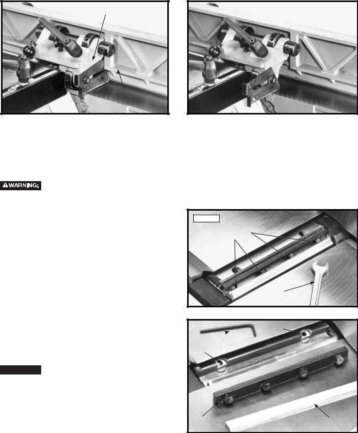
REPLACING AND RESETTING KNIVES
If the knives are removed from the cutterhead for replacement or sharpening, care must be used in removing, replacing and resetting them. Proceed as follows:
1.

 Disconnect machine from power source.
2.Move the fence to the rear and remove the cutterhead guard (C) Fig. 40.
Be extremely careful that your hands do not come in contact with the knives.
3.Using 8x10 mm open end wrench (A) Fig. 57, slightly loosen the four locking screws (B) in each knife slot by turning the screws (B) clockwise. This relieves stress in the cutterhead.
4.Loosen screws (B) Fig. 57, further and remove knife and knife locking bar.
5.Fig. 58, illustrates the knife (C) and knife locking bar (D) removed from the cutterhead. Remove the remaining two knives and locking bars, in the same manner.
6.Using the 2.5mm allen wrench (E) Fig. 58, lower the two knife adjustment blocks by turning screws (F) counterclockwise in all three slots of the cutterhead.
7.Before replacing knives make certain the knife locking bars are thoroughly clean and free of gum and pitch.
8.Place the knife locking bars (D) Fig. 58, and knives (C) into each slot in the cutterhead.


 CARE MUST BE TAKEN WHEN INSERTING THE KNIVES AS THE CUTTING EDGES ARE VERY SHARP. Push the knife down us-
ing a scrap piece of wood as far as possible and turn each screw (B) Fig. 57, counterclockwise just enough to hold the knife in position. Replace the remaining two knives in the same manner. NOTE: Knives must be installed correctly as shown in Fig. 59.
Fig. 57
B
B
A
F
E 
F
D |
|
C |
|
Fig. 58 |
|||
|
|
20 - English
9.The knives are adjusted correctly when the cutting edge of the knife extends out .060" (1.5 mm) from the cutterhead diameter.
10.Carefully rotate the cutterhead (G) Fig. 60, until the round portion of the cutterhead is on top as shown.
11.Place a .060" (1.5 mm) feeler gage (H) Fig. 60, on the cutterhead and using a straight edge (J) on the rear table adjust the height of the rear table until it is .060" (1.5 mm) above the cuttinghead diameter.
12.Lock the rear table in position and remove the feeler gage.
13.Lower the infeed table and place a straight edge
(J)Fig. 61, on the outfeed table extending over the cutterhead as shown.
14.Rotate the cutterhead by hand until the knife is at its highest point at each end of the cutterhead. To raise the knife, use wrench (E) Fig. 61, and turn raising screw clockwise until the knife just touches the straight edge (J) on each end and center of the cutterhead when the knife is at its highest point. When you are certain the knife is adjusted properly, tighten the four locking screws (B) by turning them counterclockwise.
15.Adjust the remaining two knives in the same manner.
 Make certain that all knives are securely fastened in cutterhead before turning on power.
16. Replace cutterhead guard.
|
Mating surfaces of cutterhead to blade |
Fig. 59 |
and blade to bar to be tight and parallel |
Face of screw and face of cutterhead to be parallel
DO |
DON’T |
WARNING: Insure cutter blades are installed properly
J
H
G
Fig. 60
J
B
E
Fig. 61
B
MACHINE USE
The following directions will give the beginner a start on jointer operations. Use scrap pieces of lumber to check settings and to get the feel of the operations before attempting regular work.
NOTE: The knives on the jointer will not wear evenly by feeding the through the same spot on the table every time. Feed the wood through the jointer at different spots on the table when possible, to help eliminate uneven wear of the knives.


 Always use cutterhead guard and keep hands away from cutterhead. Always use push blocks whenever possible. Never make jointing and planning cuts deeper than 1/8" in one pass.
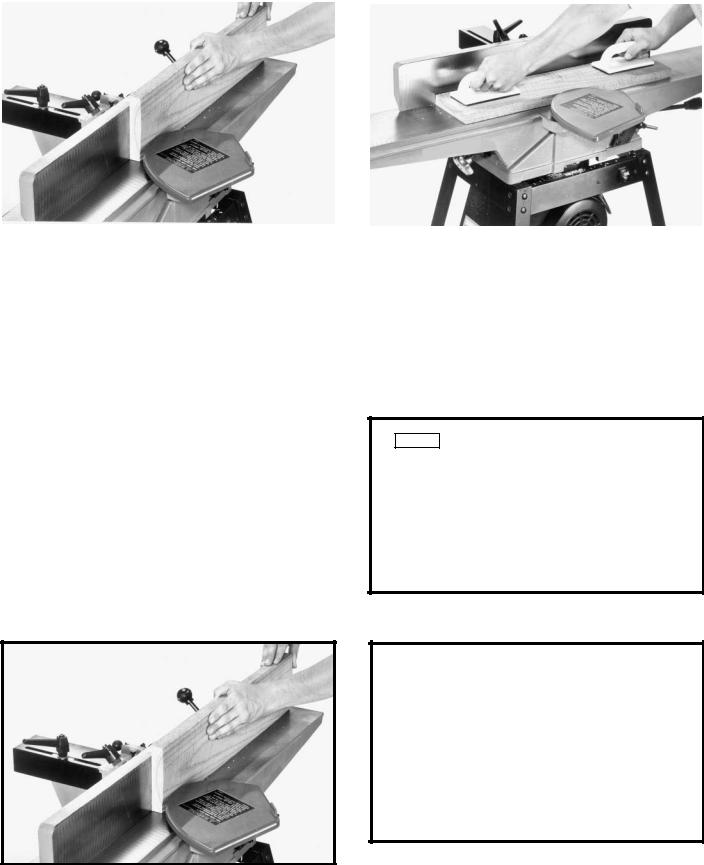
PLACEMENT OF HANDS DURING FEEDING
At the start of the cut, the left hand holds the work firmly against the infeed table and fence, while the right hand pushes the work toward the knives. After the cut is underway, the new surface rests firmly on the outfeed table as shown in Fig. 64. The left hand should then be moved to the work on the outfeed table, at the same time maintaining flat contact with the fence. The right hand presses the work forward, and before the right hand reaches the cutterhead, it should be moved to the work on the outfeed table.
Never pass hands directly over the cutterhead.
21 - English
DEFINITIONS OF JOINTING AND PLANING OPERATIONS
|
|
|
|
|
|
|
|
Fig. 62 |
|
|
|
Fig. 63 |
|
|
|
|
|
|
|
|
1.JOINTING OPERATIONS – Jointing cuts or edge jointing are made to square an edge of a workpiece. The workpiece is positioned on the jointer with the narrow edge of the workpiece on the infeed table and the major flat surface of the workpiece against the fence, as shown in Fig. 62. The workpiece is moved from the infeed table, across the cutterhead to the outfeed table.
JOINTING AN EDGE
This is the most common operation for the jointer. Set the guide fence square with the table. Depth of cut should be the minimum required to obtain a straight edge. Hold the best face of the piece firmly against the fence throughout the feed as shown in Fig. 65. Maximum depth of cut should not be more than 1/8" (3.175 mm) in one pass.


 Do not perform jointing operations on material shorter than 10" (254 mm), narrower than
3/4" (19 mm), or less that 1/2" (12.7 mm) thick. See Fig. 66.
2.PLANING OPERATIONS – Planing or surfacing are identical to the jointing operation except for the position of the workpiece. For planing, the major flat surface of the workpiece is placed on the infeed table of the jointer with the narrow edge of the workpiece against the fence, as shown in Fig. 63. The workpiece is moved from the infeed table, across the cutterhead to the outfeed table. Use push blocks when performing planing operations whenever possible.
Fig. 64
|
WORK |
OUT-FEED |
IN-FEED TABLE |
TABLE |
|
|
CUTTER |
Fig. 65 |
|
Fig. 66 |
|
|
|
MINIMUM JOINTING
DIMENSIONS
10" |
(254 |
|
MINIMUM mm)
1/2" (12.7 mm) |
3/4" (19 mm) MINIMUM |
|
MINIMUM |
||
|
22 - English
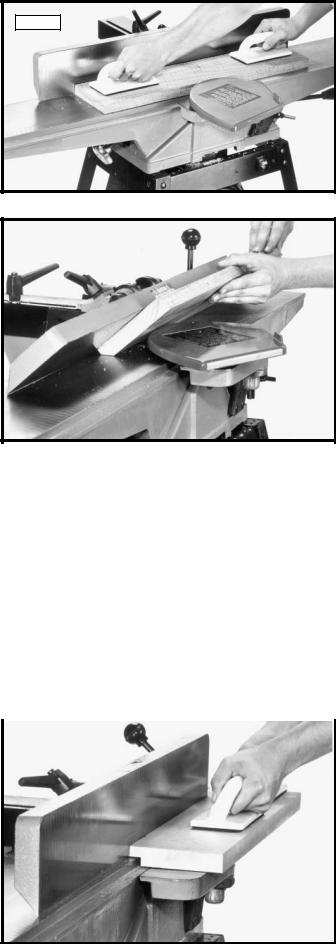
PLANING OR SURFACING
Fig. 67
Planing or surfacing is identical to the jointing operation except for the position of the workpiece. For planing, the major flat surface of the workpiece is placed on the infeed table of the jointer with the narrow edge of the workpiece against the fence, a shown in Fig. 67. The workpiece is moved from the infeed table, across the cutterhead to the outfeed table establishing a flat surface on the workpiece Always use push blocks when performing planing operations and never pass your hands directly over the cutterhead. Maximum depth of cut should not be more than 1/8" in one pass.
BEVELING |
Fig. 68 |
|
To cut a bevel, lock the fence at the required angle and run the work across the knives while keeping the work firmly against the fence and tables. Several passes may be necessary to arrive at the desired result. When the angle is small, there is little difference whether the fence is tilted to the right or left. However, at greater angles approaching 45 degrees, it is increasingly difficult to hold the work properly when the fence is tilted to the right. The advantage of the double-tilting fence is appreciated under such conditions.
When tilted to the left, the fence forms a V-shape with the tables, and the work is easily pressed into the pocket while passing it across the knives as shown in Fig. 68. If the bevel is laid out on the piece in such direction that this involves cutting against the grain, it will be better to tilt the fence to the right.
TAPER CUTS
One of the most useful jointer operations is cutting an edge to a taper. This method can be used on a wide variety of work. Tapered legs of furniture are a common example.
Instead of laying the piece on the infeed table, lower the forward end of the work onto the outfeed table. Do this very carefully, as the piece will span the knives, and they will take a "bite" from the work with a tendency to kick back unless the piece is firmly held. Now push the work forward as in ordinary jointing. The effect is to plane off all the stock in front of the knives, to increasing depth, leaving a tapered surface.
The ridge left by the knives when starting the taper may be removed by taking a very light cut according to the regular method for jointing, with the infeed table raised to its usual position.
Practice is required in this operation, and the beginner is advised to make trial cuts on waste material. Taper cuts over part of the length and a number of other special operations can easily be done by the experienced craftsman.
CUTTING A RABBET |
|
|
|
|
Fig. 69 |
|
|
When making a rabbet cut, as shown in Fig. 69, |
|
|
|
|
|
|
|
the cutterhead guard must be removed. AFTER THE |
|
|
|
RABBET CUT IS COMPLETED, BE CERTAIN GUARD |
|
|
|
IS REPLACED. |
|
|
|
1.Adjust the fence so that the distance between the end of the knives and the fence is equal to the width of the rabbet.
2.Lower the infeed table an amount equal to the depth of the rabbet. If the rabbet is quite deep, it may be necessary to cut it in two or more passes. In that event, the table is lowered an amount equal to about half the depth of the rabbet for the first pass, then lowered again to proper depth to complete the cut. Maximum depth of cut when rabbeting with this jointer is 1/2 inch.
23 - English
 Loading...