


8" Variable Speed Grinder
Meuleuse à vitesse variable de 203 mm (8 po)
Amoladora de
203 mm (8 pulgadas) de velocidad variable
Français (16)
Español (30)
Instruction manual
Manuel d’utilisation
Manual de instrucciones
www.deltaportercable.com
INSTRUCTIVO DE OPERACIÓN, CENTROS
DE SERVICIO Y PÓLIZA DE GARANTÍA.
 LÉASE ESTE INSTRUCTIVO
ANTES DE USAR EL PRODUCTO.
GR450

TABLE OF CONTENTS
IMPORTANT SAFETY INSTRUCTIONS..................... |
2 |
TROUBLESHOOTING................................................. |
14 |
safety guidelines - definitions...................... |
2 |
MAINTENANCE.......................................................... |
14 |
GENERAL SAFETY RULES........................................ |
3 |
ACCESSORIES........................................................... |
14 |
ADDITIONAL SPECIFIC SAFETY RULES ................ |
4 |
SERVICE...................................................................... |
14 |
FUNCTIONAL DESCRIPTION.................................... |
6 |
WARRANTY................................................................ |
15 |
CARTON CONTENTS ................................................ |
7 |
FranÇais................................................................... |
16 |
assembly.................................................................. |
8 |
ESPAÑOL.................................................................... |
30 |
operation................................................................ |
10 |
|
|
IMPORTANT SAFETY INSTRUCTIONS
Read and understand all warnings and operating instructions before using any tool
or equipment. When using tools or equipment, basic safety precautions should always be followed to reduce the risk of personal injury. Improper operation, maintenance or modification of tools or equipment could result in serious injury and property damage. There are certain applications for which
tools and equipment are designed. Delta Machinery strongly recommends that this product NOT be modified and/or used for any application other than for which it was designed.
If you have any questions relative to its application DO NOT use the product until you have written Delta Machinery and we have advised you. Contact us online at www.deltaportercable.com or by mail at Technical Service Manager, Delta Machinery, 4825 Highway 45 North, Jackson, TN 38305. In Canada,125 Mural St. Suite 300, Richmond Hill, ON, L4B 1M4)
Information regarding the safe and proper operation of this tool is available from the following sources:
•Power Tool Institute, 1300 Sumner Avenue, Cleveland, OH 44115-2851or online at www.powertoolinstitute.org
•National Safety Council, 1121 Spring Lake Drive, Itasca, IL 60143-3201
•American National Standards Institute, 25 West 43rd Street, 4 floor, New York, NY 10036 www.ansi.org - ANSI 01.1 Safety Requirements for Woodworking Machines
•U.S. Department of Labor regulations www.osha.gov
SAVE THESE INSTRUCTIONS!
safety guidelines - definitions
It is important for you to read and understand this manual. The information it contains relates to protecting YOUR SAFETY and PREVENTING PROBLEMS. The symbols below are used to help you recognize this information.
Indicates an imminently hazardous situation which, if not avoided, will result in death or serious injury.
Indicates a potentially hazardous situation which, if not avoided, could result in death or serious injury.
Indicates a potentially hazardous situation which, if not avoided, may result in minor or moderate injury.
Used without the safety alert symbol indicates potentially hazardous situation which, if not avoided, may result in property damage.
CALIFORNIA PROPOSITION 65
 Some dust created by power sanding, sawing, grinding, drilling, and other construction activities contains chemicals known to cause cancer, birth defects or other reproductive harm. Some examples of these chemicals are:
•lead from lead-based paints,
•crystalline silica from bricks and cement and other masonry products, and
•arsenic and chromium from chemically-treated lumber.
Your risk from these exposures varies, depending on how often you do this type of work. To reduce your exposure to these chemicals: work in a well ventilated area, and work with approved safety equipment, always wear NIOSH/OSHA approved, properly fitting face mask or respirator when using such tools.
2

GENERAL SAFETY RULES
Failure to follow these rules may result in serious personal injury.
1.FOR YOUR OWN SAFETY, READ THE INSTRUCTION MANUAL BEFORE OPERATING THE MACHINE. Learning the machine’s application, limitations, and specific hazards will greatly minimize the possibility of accidents and injury.
2.WEAR EYE AND HEARING PROTECTION. ALWAYS USE SAFETY GLASSES. Everyday eyeglasses are NOT safety glasses. USE CERTIFIED SAFETY EQUIPMENT. Eye protection equipment should comply with ANSI Z87.1 standards. Hearing equipment should comply with ANSI S3.19 standards.
3.WEAR PROPER APPAREL. Do not wear loose clothing, gloves, neckties, rings, bracelets, or other jewelry which may get caught in moving parts. Nonslip protective footwear is recommended. Wear protective hair covering to contain long hair.
4.DO NOT USE THE MACHINE IN A DANGEROUS ENVIRONMENT. The use of power tools in damp or wet locations or in rain can cause shock or electrocution. Keep your work area well-lit to prevent tripping or placing arms, hands, and fingers in danger.
5.MAINTAIN ALL TOOLS AND MACHINES IN peak CONDITION. Keep tools sharp and clean for best and safest performance. Follow instructions for lubricating and changing accessories. Poorly maintained tools and machines can further damage the tool or machine and/or cause injury.
6.CHECK FOR DAMAGED PARTS. Before using the machine, check for any damaged parts. Check for alignment of moving parts, binding of moving parts, breakage of parts, and any other conditions that may affect its operation. A guard or any other part that is damaged should be properly repaired or replaced with Delta or factory authorized replacement parts. Damaged parts can cause further damage to the machine and/or injury.
7.KEEP THE WORK AREA CLEAN. Cluttered areas and benches invite accidents.
8.KEEP CHILDREN AND VISITORS AWAY. Your shop is a potentially dangerous environment. Children and visitors can be injured.
9.REDUCE THE RISK OF UNINTENTIONAL STARTING. Make sure that the switch is in the “OFF” position before plugging in the power cord. In the event of a power failure, move the switch to the “OFF” position. An accidental start-up can cause injury. Do not touch the plug’s metal prongs when unplugging or plugging in the cord.
10.USE THE GUARDS. Check to see that all guards are in place, secured, and working correctly to prevent injury.
11.REMOVE ADJUSTING KEYS AND WRENCHES BEFORE STARTING THE MACHINE. Tools, scrap pieces, and other debris can be thrown at high speed, causing injury.
12.USE THE RIGHT MACHINE. Don’t force a machine or an attachment to do a job for which it was not designed. Damage to the machine and/or injury may result.
13.USE RECOMMENDED ACCESSORIES. The use of accessories and attachments not recommended by Delta may cause damage to the machine or injury to the user.
14.USE THE PROPER EXTENSION CORD. Make sure your extension cord is in good condition. When using an extension cord, be sure to use one heavy enough to carry the current your product will draw. An undersized cord will cause a drop in line voltage, resulting in loss of power and overheating. See the Extension Cord Chart for the correct size depending on the cord length and nameplate ampere rating. If in doubt, use the next heavier gauge. The smaller the gauge number, the heavier the cord.
15.SECURE THE WORKPIECE. Use clamps or a vise to hold the workpiece when practical. Loss of control of a workpiece can cause injury.
16.FEED THE WORKPIECE AGAINST THE DIRECTION OF THE ROTATION OF THE BLADE, CUTTER, OR ABRASIVE SURFACE. Feeding it from the other direction will cause the workpiece to be thrown out at high speed.
17.DON’T FORCE THE WORKPIECE ON THE MACHINE.
Damage to the machine and/or injury may result.
18.DON’T OVERREACH. Loss of balance can make you fall into a working machine, causing injury.
19.NEVER STAND ON THE MACHINE. Injury could occur if the tool tips, or if you accidentally contact the cutting tool.
20.NEVER LEAVE THE MACHINE RUNNING UNATTENDED. TURN THE POWER OFF. Don’t leave the machine until it comes to a complete stop. A child or visitor could be injured.
21.Turn the machine “OFF”, and disconnect the machine from the power source before installing or removing accessories, changing cutters, adjusting or changing set-ups. When making repairs, be sure to lock the start switch in the “OFF” position. An accidental start-up can cause injury.
22.MAKE YOUR WORKSHOP CHILDPROOF WITH PADLOCKS, MASTER SWITCHES, OR BY REMOVING STARTER KEYS. The accidental start-up of a machine by a child or visitor could cause injury.
23. STAY ALERT, WATCH WHAT YOU ARE DOING, AND USE
COMMON SENSE. DO NOT USE THE MACHINE WHEN YOU ARE TIRED OR UNDER THE INFLUENCE OF DRUGS, ALCOHOL, OR MEDICATION. A moment of inattention while operating power tools may result in injury.
24.  Use of this tool can generate and disburse dust or other airborne particles, including wood dust, crystalline silica dust and asbestos dust. Direct particles away from face and body. Always operate tool in well ventilated area and provide for proper dust removal. Use dust collection system wherever possible. Exposure to the dust may cause serious and permanent respiratory or other injury, including silicosis (a serious lung disease), cancer, and death. Avoid breathing the dust, and avoid prolonged contact with dust. Allowing dust to get into your mouth or eyes, or lay on your skin may promote absorption of harmful material. Always use properly fitting NIOSH/OSHA approved respiratory protection appropriate for the dust exposure, and wash exposed areas with soap and water.
3

ADDITIONAL SPECIFIC SAFETY RULES
 Failure to follow these rules may result in serious personal injury.
1.Do not operate this machine until it is completely assembled and installed according to the instructions. A machine incorrectly assembled can cause serious injury.
2.OBTAIN ADVICE from your supervisor, instructor, or another qualified person if you are not thoroughly familiar with the operation of this machine. Knowledge is safety.
3.FOLLOW ALL WIRING CODES and recommended electrical connections to prevent shock or electrocution.
4.ALWAYS USE THE PROVIDED BLOTTER and wheel flanges to mount the grinding wheels on the grinder shaft to prevent wheel damage or acciden-tal separation. Separation can result in fragments flying off the wheel at high speeds.
5.USE ONLY WHEELS suitable for the speed of the machine. Unsuitable grinding wheels can come apart, throwing fragments out at high speeds.
6.USE ONLY WHEELS that have a bore exactly equal to the arbors of the machine. Never attempt to machine an undersized wheel to fit an arbor. Unsuitable grinding wheels can come apart, throwing fragments out at high speeds.
7.DO NOT overtighten wheel nut.
8.DO NOT USE A WHEEL THAT VIBRATES. Dress the grinding wheel, replace it, or replace the bearings of the shaft. Unsuitable grinding wheels can come apart, throwing fragments at high speeds.
9.INSPECT WHEELS before starting the machine for cracks or fragments. REPLACE DAMAGED WHEELS immediately. Parts of the wheel can be thrown at high speeds causing serious injury.
10.ADJUST EYE SHIELDS close to the grinding wheel, and re-adjust as the wheel wears down. Flying sparks are dangerous and can cause fires or explosions.
11.ALWAYS MAKE SURE the eye shields are in place, properly adjusted, and secured.
12.ADJUST TOOL RESTS close to the grinding wheel (1/8" separation or less). Tighten the tool rest securely to prevent shifting positions, and re-adjust as the wheel wears down. The workpiece can be drawn into the wheel, causing damage to the workpiece and/or serious injury.
13.Stand to one side before turning the machine "ON". Loose fragments or wheel parts could fly from the wheel at high speeds.
14.NEVER GRIND ON A COLD WHEEL. Run the grinder for one full minute before applying the workpiece. A cold wheel has a tendency to chip. Those fragments could fly from the wheel at high speeds.
15.Never start the machine with the workpiece against the grinding wheel. The workpiece can be drawn into the wheel, causing damage to the machine and/or serious injury.
16.CLEAN THE MACHINE thoroughly when processing different types of workpieces (wood, steel, or aluminum). Combining wood and metal dust can create an explosion or fire hazard. DO NOT GRIND or polish magnesium. Fire will result.
17.NEVER GRIND NEAR FLAMMABLE GAS OR LIQUIDS.
Sparks can create a fire or an explosion.
18.AVOID awkward operations and hand positions. A sudden slip could cause a hand to move into the grinding wheel.
19.KEEP ARMS, HANDS, and fingers away from the wheel. The abrasive surfaces can cause serious injury.
20.HOLD THE WORKPIECE FIRMLY against the tool rest. Loss of control of the workpiece can cause serious injury.
21.DRESS THE WHEEL on the face only. Dressing the side of the wheel could cause it to become too thin for safe use.
22.GRIND A WORKPIECE using the face of the grinding wheel only. Loss of control of the workpiece can cause serious injury.
23.NEVER APPLY COOLANT directly to the grinding wheel. Coolant can weaken the bonding strength of the grinding wheel and cause it to fail. Dip the workpiece in water to cool it.
24.DO NOT TOUCH the ground portion of a workpiece until it has cooled sufficiently. Grinding creates heat.
25.PROPERLY SUPPORT LONG OR WIDE workpieces. Loss of control of the workpiece can cause serious injury.
26.Never Perform layout, assembly, or set-up work on the table/work area when the machine is running. A sudden slip could cause a hand to move into the wheel. Severe injury can result.
27.Turn the machine "OFF", disconnect the machine from the power source, and clean the table/work area before leaving the machine. Lock the switch in the "OFF" position to prevent unauthorized use. Someone else might accidentally start the machine and cause serious injury to themselves.
28.ADDITIONAL INFORMATION regarding the safe and proper operation of power tools (i.e. a safety video) is available from the Power Tool Institute, 1300 Sumner Avenue, Cleveland, OH 44115-2851 (www. powertoolinstitute.com). Information is also available from the National Safety Council, 1121 Spring Lake Drive, Itasca, IL 60143-3201. Please refer to the American National Standards Institute ANSI 01.1 Safety Requirements for Woodworking Machines and the U.S. Department of Labor OSHA 1910.213 Regulations.
SAVE THESE INSTRUCTIONS.
Refer to them often and use them to instruct others.
4
POWER CONNECTIONS
A separate electrical circuit should be used for your machines. This circuit should not be less than #12 wire and should be protected with a 20 Amp time lag fuse. If an extension cord is used, use only 3-wire extension cords which have 3-prong grounding type plugs and matching receptacle which will accept the machine’s plug. Before connecting the machine to the power line, make sure the switch (s) is in the "OFF" position and be sure that the electric current is of the same characteristics as indicated on the machine. All line connections should make good contact. Running on low voltage will damage the machine.
 Do not expose the machine to rain or operate the machine in damp locations.
MOTOR SPECIFICATIONS
Your machine is wired for 120 volts, 60 HZ alternating current. Before connecting the machine to the power source, make sure the switch is in the "OFF" position.
GROUNDING INSTRUCTIONS
 This machine must be grounded while in use to protect the operator from electric shock.
1.All grounded, cord-connected machines:
In the event of a malfunction or breakdown, grounding provides a path of least resistance for electric current to reduce the risk of electric shock. This machine is equipped with an electric cord having an equipment-grounding conductor and a grounding plug. The plug must be plugged into a matching outlet that is properly installed and grounded in accordance with all local codes and ordinances.
Do not modify the plug provided - if it will not fit the outlet, have the proper outlet installed by a qualified electrician.
Improper connection of the equipment-grounding conduc-tor can result in risk of electric shock. The conductor with insulation having an outer surface that is green with or without yellow stripes is the equipment-grounding conductor. If repair or replacement of the electric cord or plug is necessary, do not connect the equipment-grounding conductor to a live terminal.
Check with a qualified electrician or service personnel if the grounding instructions are not completely understood, or if in doubt as to whether the machine is properly grounded.
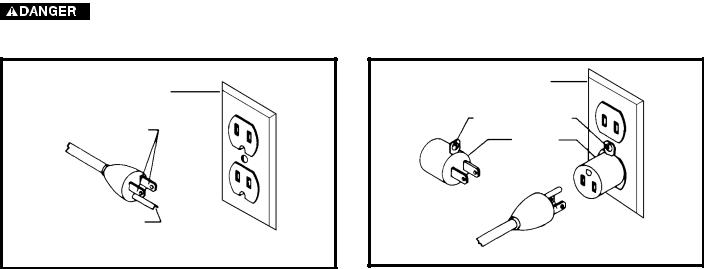
Use only 3-wire extension cords that have 3-prong grounding type plugs and matching 3-conductor receptacles that accept the machine’s plug, as shown in Fig. A.
Repair or replace damaged or worn cord immediately.
2.Grounded, cord-connected machines intended for use on a supply circuit having a nominal rating less than 150 volts:
If the machine is intended for use on a circuit that has an outlet that looks like the one illustrated in Fig. A, the machine will have a grounding plug that looks like the plug illustrated in Fig. A. A temporary adapter, which looks like the adapter illustrated in Fig. B, may be used to connect this plug to a matching 2-conductor receptacle as shown in Fig. B if a properly grounded outlet is not available. The temporary adapter should be used only until a properly grounded outlet can be installed by a qualified electrician. The green-colored rigid ear, lug, and the like, extending from the adapter must be connected to a permanent ground such as a properly grounded outlet box. Whenever the adapter is used, it must be held in place with a metal screw.
NOTE: In Canada, the use of a temporary adapter is not permitted by the Canadian Electric Code.
In all cases, make certain that the receptacle in question is properly grounded. If you are not sure, have a qualified electrician check the receptacle.
|
GROUNDED OUTLET BOX |
||
GROUNDED OUTLET BOX |
|
|
|
CURRENT |
GROUNDING MEANS |
||
|
|
|
|
CARRYING |
|
|
|
|
ADAPTER |
|
|
PRONGS |
|
|
|
|
|
|
|
|
|
|
|
GROUNDING BLADE
IS LONGEST OF THE 3 BLADES
Fig. A |
Fig. B |
5

EXTENSION CORDS
 Use proper extension cords. Make sure your extension cord is in good condition and is a 3-wire extension cord which has a 3-prong grounding type plug and matching receptacle which will accept the machine’s plug. When using an extension cord, be sure to use one heavy enough to carry the current of the machine. An undersized cord will cause a drop in line voltage, resulting in loss of power and overheating. Fig. D-1, shows the correct gauge to use depending on the cord length. If in doubt, use the next heavier gauge. The smaller the gauge number, the heavier the cord.
MINIMUM GAUGE EXTENSION CORD
RECOMMENDED SIZES FOR USE WITH STATIONARY ELECTRIC MACHINES
|
|
Total |
|
Ampere |
|
Length of |
|
|
Cord in |
Gauge of Extension |
|
|
|
||
Rating |
Volts |
Feet |
Cord |
0-6 |
120 |
up to 25 |
18 AWG |
0-6 |
120 |
25-50 |
16 AWG |
0-6 |
120 |
50-100 |
16 AWG |
0-6 |
120 |
100-150 |
14 AWG |
6-10 |
120 |
up to 25 |
18 AWG |
6-10 |
120 |
25-50 |
16 AWG |
6-10 |
120 |
50-100 |
14 AWG |
6-10 |
120 |
100-150 |
12 AWG |
10-12 |
120 |
up to 25 |
16 AWG |
10-12 |
120 |
25-50 |
16 AWG |
10-12 |
120 |
50-100 |
14 AWG |
10-12 |
120 |
100-150 |
12 AWG |
12-16 |
120 |
up to 25 |
14 AWG |
12-16 |
120 |
25-50 |
12 AWG |
12-16 |
120 |
greater than 50 feet not recommended |
|
|
|
Fig. D-1 |
|
FUNCTIONAL DESCRIPTION
FOREWORD
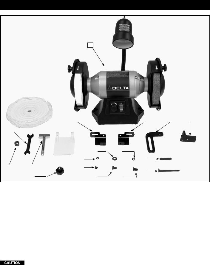
The Delta GR450 is an 8" Variable Speed Grinder. This model comes with a flexible lamp, adjustable tool rests, buffing wheel, quick release arbor nut system, and two large eye shields for added safety.
NOTICE: The photo on the manual cover illustrates the current production model. All other illustrations contained in the manual are representative only and may not depict the actual labeling or accessories included. These are intended to illustrate technique only.
6
CARTON CONTENTS
1
|
|
|
|
|
2 |
|
|
|
|
|
|
|
|
|
|
|
|
|
|
|
|
|
|
|
|
|||
|
|
|
|
|
|
|
|
|
|
|
|
|
|
|
|
|
|
|
|
|
|
|
|
|
|
|
|
|
|
|
|
|
|
|
|
|
|
|
|
|
|
7 |
|
|
|
|
|
|
|
|
8 |
|
9 |
|
10 |
|
|
|
|
|
|
|
|
|
|
|
|
|
|
|
|
|
|
|
|
|
|
|
|
|
|
|
|
|
|
|
|
|
4 |
|
|
|
|
|
|
|
|
|
|
|
|
|
|
|
|
|
|
|
|
|
|
|
|
|
|
|
|
|
|
|
|
|
|
|
|
|
|
|
|
|
|
|
|
|
|
|
|
|
|
|
|
|
|
|
|
|
|
|
|
|
|
|
|
|
|
6 |
|
|
|
|
|
|
|
|
|
|
|
|
|
|
|
|
|
|
|
|
|
|
|
|
|
|
|
|
|
|
|
|
|
|
14 |
|
16 |
|
|
|
|
|
|
|
|
|
|
|
|
|
|
|
|
|
|
|
|
|
|
|
|
|
|
|
|
|
|
|
|
|
|
|
|
|
|
|
|
|
|
|
|
|
|
|
|
|
|
|
|
|
12 |
|
|
|
|
|
18 |
|
|
|
|
|
|
|
|
|
|
|
|
|
|
|
|
|
|
|
|
|
|
|
|
|
|
|
|
|
|
|
|
|
|
|
|
|
|
|
|
|
|
|
|
|
|
|
|
|
|
|
|
|
|
|
|
|
|
|
|
|
|
|
|
|
|
3 |
|
|
5 |
|
|
|
13 |
|
|
|
|
|
|
|
|
|
|
|
|
|
|||||||
|
|
|
|
|
|
|
|
|
|
|
|
|
|
|
|
|
|
|
|
|
19 |
|
|
|
|
|
|
|
|
|
|
|
|
|
|
|
|
|
|
|
|
|
|
|
|
|
|
|
|
|
|
|
|
|
|
|
|
|
|
|
|
|
|
|
|
11 |
|
|
|
|
|
|
|
15 |
|
17 |
|
|
|
|
|
|
|
|
|
|
|
|
|
|
|
|
|
|
|
|
|
|
|
|
|
|
|
|
|
|
|||||||||
|
|
|
|
|
|
|
|
|
|
|
|
|
|
|
|
|
|
|
|
|||||||||
|
|
|
|
|
|
|
|
|
|
|
|
|
|
|
|
|
|
|
|
|
|
|
|
|
|
|
|
|
1. |
|
Grinder |
|
|
|
|
|
|
|
11. |
Eye Shield Knob (2) |
|
|
|
|
|||||||||||||
2. |
|
Buffing Wheel |
|
|
|
|
|
|
|
12. |
1/4" Flat Washer (4) |
|
|
|
|
|||||||||||||
3. |
|
Buffing Wheel Bushing |
|
|
|
|
|
|
|
13. |
1/4-20x1/4" Hex Head Screw (2) |
|
|
|||||||||||||||
4. |
|
Wrench |
|
|
|
|
|
|
|
14. |
3/4" Flat Washer (4) |
|
|
|
|
|||||||||||||
5. |
|
Wheel Dresser |
|
|
|
|
|
|
|
15. |
5/16-18 x 1/2" Hex Head Screw (4) |
|
|
|||||||||||||||
6. |
|
Eye Shield (2) |
|
|
|
|
|
|
|
16. |
5/16" Lockwasher (2) |
|
|
|
|
|||||||||||||
7. |
|
Left Side Spark Guard |
|
|
|
|
|
|
|
17. |
5/16-18x3/4" Hex Head Screw (2) |
|
|
|||||||||||||||
8. |
|
Right Side Spark Guard |
|
|
|
|
|
|
|
18. |
Eye Shield Spacer (2) |
|
|
|
|
|||||||||||||
9. |
|
Tool Rest Arm (2) |
|
|
|
|
|
|
|
19. |
Eye Shield Bolt (2) |
|
|
|
|
|||||||||||||
10. |
Tool Rest (2) |
|
|
|
|
|
|
|
|
|
|
|
|
|
|
|
|
|
|
|||||||||
UNPACKING AND CLEANING
Carefully unpack the machine and all loose items from the shipping container(s). Remove the rust-preventative oil from unpainted surfaces using a soft cloth moistened with mineral spirits, paint thinner or denatured alcohol.
Do not use highly volatile solvents such as gasoline, naphtha, acetone or lacquer thinner for cleaning your machine.
After cleaning, cover the unpainted surfaces with a good quality household floor paste wax.
7
assembly
 For your own safety, do not connect the machine to the power source until the machine is completely assembled and you read and understand the entire instruction manual.
ASSEMBLY TOOLS REQUIRED
Open end wrench (supplied)
ASSEMBLY TIME ESTIMATE
Assembly for this machine takes approximately 30 minutes.
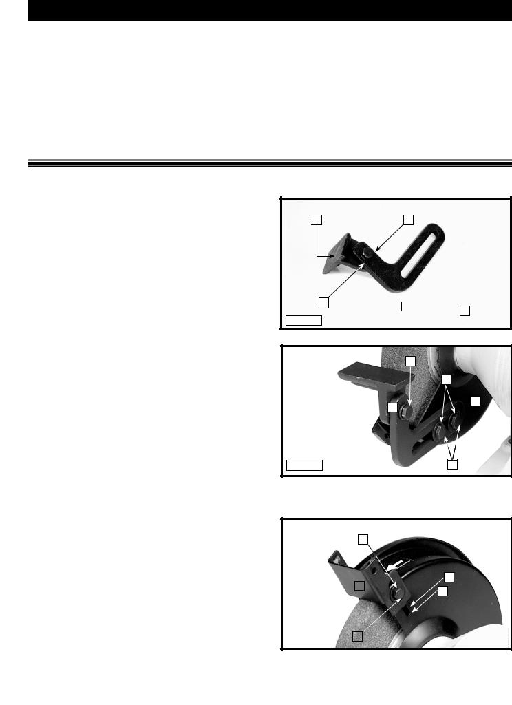
TOOL RESTS
1.Attach the adjustable tool rest (A) Fig. 1 to the left side of the tool rest arm (B), and fasten with one 5/16-18 x 3/4" hex head screw (C) and 5/16"
lockwasher (D). Attach |
the remaining tool rest |
to the right side of the |
tool. Loosely tighten the |
hardware for further adjustment.
2.Attach the left tool rest assembly (D) Fig. 2 to the inside of the left wheel guard (E), and fasten with two 5/16-18 x 1/2" screws (F) and 3/4" flat washers
(G).
3.Attach the right tool rest assembly to the inside of the right wheel guard and fasten with two 5/1618 x 1/2" hex head screws and 3/4" flat washers.
4.Each tool rest assembly (D) Fig. 4 is adjustable. Each can be positioned slightly below the centerline of the wheel and as close to the grinding wheel as possible, giving maximum support to the workpiece. Maintain a distance of 1/8" or less between the grinding wheel and the inside edge of the tool rest. Adjust the tool rest when the grinding wheel wears down. When the tool rest is positioned correctly, tighten the hardware, (C) and (F) Fig. 2. Freehand grinding without the use of a tool rest should always be done on the lower quarter of the wheel.
A |
C |
D 

 B
B
Fig. 1
|
C |
|
A |
D |
E |
|
Fig. 2 |
F |
Spark guards
The spark guard (A) Fig. 3 is mounted to the side of each
wheel guard, using a 1/4-20 x 1/4" hex head screw (B) C Fig. 3 and a 1/4" flat washer (C).
NOTE: The tab (D) Fig. 3 on the side of the spark guard |
|
|
|
|
|
|
(A) must be placed in slot (E), before attaching the spark |
|
|
|
|
|
D |
guard (A) to the grinder. |
|
|
|
A |
E |
|
|
|
|
|
|
||
|
|
|
|
|
|
|
Adjust the spark guard (A) as close as possible to the |
|
|
|
|
|
|
grinding wheel so that sparks never strike the operator’s |
|
|
|
|
|
|
hand. As the wheels wear down, adjust the spark guard |
|
|
|
|
|
|
(A) accordingly. |
|
|
|
|
|
|
|
|
B |
|
|||
Fig. 3 |
|
|
|
|||
|
|
|
|
|
|
|
8
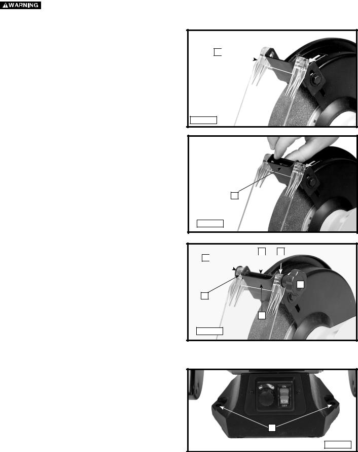
eye shields
Your grinder is supplied with two shields to protect your eyes.
Always wear eye protection.
To attach the eye shields:
1.Place the eye shield (A) Fig. 4 on the spark guard.
2.Align the holes in the eye shield with the holes in the spark guard. Place the eye shield spacer (A) Fig. 5 in the space in the spark guard.
A 
Fig. 4
A
Fig. 5
3.Insert the eye shield bolt (A) Fig. 6 through the hole in the eye shield (B), the eye shield spacer (C), and the spark guard (D).
4.Place a 1/4" flat washer (E) Fig. 6 on the end of the eye shield bolt. Attach the eye shield knob (F) to the end of the eye shield bolt.
5.Install the other eye shield in the same manner.
C E A 


F
B
D
Fig. 6
fastening THE grinder A supporting surface
If the grinder has a tendency to tip over, slide, or walk, secure it to the supporting surface, using fasteners (not supplied) through the two holes (A) Fig. 7 in the grinder base.
A
Fig. 7
9
operation
OPERATIONAL Controls and ADJUSTMENTS
STARTING AND STOPPING THE GRINDER
 Make sure that the switch is in the "OFF" position before plugging cord into outlet. Do not touch the plug’s metal prongs when unplugging or plugging in the cord.
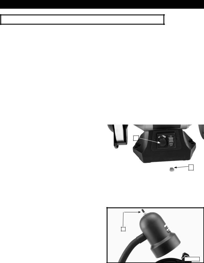
The on/off switch (A) Fig. 8 is located on the front of the grinder. To turn the machine "ON", move the switch up to the "ON" position. To turn the machine "OFF", move the switch (A) down to the "OFF" position.
LOCKING SWITCH IN THE "OFF" POSITION
IMPORTANT: When the machine is not in use, the switch should be locked in the "OFF" position to prevent unauthorized use. To lock the machine, grasp the switch toggle (A) and pull it out of the switch (Fig. 8). With the switch toggle (A) removed, the switch will not operate. However, should the switch toggle be removed while the grinder is running, the machine can be turned "OFF," but cannot be restarted without re-inserting the switch toggle (A).


 In the event of a power outage (such as a breaker or fuse trip), always move the switch to the "OFF" position until the main power is restored.
VARIABLE SPEED CONTROL |
|
|
|
|
|
|
|
|
|
|
|
|
|
||
|
|
|
|
B |
|||
The grinder is equipped with a variable speed control |
|
|
|
|
|
|
|
(B) Fig. 8. When the variable speed control knob is |
|
|
|
|
|
|
|
positioned at the far left position (counter clockwise), the |
|
|
|
|
|
|
|
RPM is 1725. The rotation increases when the variable |
|
|
|
|
|
|
|
|
|
|
|
|
A |
||
speed control knob is turned clockwise. Positioned far |
|
|
|
|
|
|
|
|
|
|
|
|
|
|
|
right, the RPM is 3450. |
|
|
|
|
|
|
|
|
Fig. 8 |
|
|
|
|
|
|
|
|
|
|
|
|
|
|
FLEXIBLE LAMP
The flexible lamp operates independently of the grinder. To turn the lamp on and off, rotate the switch (A) Fig. 10.
 To reduce the risk of fire, use 40 watt or smaller, 120 volt, reflector track type light bulb (not supplied). A standard household light bulb should not be used. The reflector track type light bulb should not extend below the lamp shade.
A
Fig. 9
10
grinding wheels
The use of accessories and attachments not recommended by Delta may result in a risk of injury.
Grinding wheels used with this grinder should be rated for 3600 RPM or higher, 8" in diameter with a 5/8" arbor hole, and 1" wide.
Using wheels less than 1" wide will cause vibration and could damage the machine.
Two aluminum oxide grinding wheels (36 grit and 60 grit) are supplied with your grinder. For best results, and to maintain balance, keep the wheels properly dressed. Do not force the work against a cold wheel. The grinding wheel should always be run for one full minute before applying a workpiece. Use only balanced wheels with your grinder. Using balanced wheels adds years to the life of the bearings on the grinder. By eliminating the most common source of vibration, your grinding projects will be more accurate.
ALWAYS maintain a distance of 1/8" or less between the grinding wheel and the tool rest. Adjust the tool rests and spark guards as the grinding wheels decrease in size with use.
DRESSING A GRINDING WHEEL
Use a suitable silicone carbide stick type dresser or the wheel dresser provided with the grinder (Fig. 11). Bring the dresser forward on the tool rest until it just touches the high point on the face of the wheel. Dress the wheel by moving the dresser back and forth. Repeat this operation until the face of the grinding wheel is clean and the edges are square.
Fig. 11
changing GRINDING wheels
Disconnect the machine from the power source.
1.Loosen the knobs (A) Fig. 12 and remove.
2.Rotate the wheel covers (B) Fig. 12 toward the rear, and remove the wheel covers.
3.Pull the two arbor nut wings (A) Fig. 13 out.
4.To loosen, place the included wrench (B) Fig. 13B on the flats of the motor shaft and brace it on the tool rest to keep the shaft from turning while removing the arbor nut (A) Fig. 13. To loosen either arbor nut, turn it toward the front of the grinder.
NOTE: If necessary, insert a flat screwdriver (A) Fig. 13B through the opening in the arbor nut and use it to provide more torque to loosen the nut.
5.Remove the arbor nut, wheel flange, and old grinding wheel.
6.Place the new grinding wheel on the arbor. NOTE: Grinding wheel must be 1" wide.
7.Place the flange on the arbor and thread the arbor nut on the arbor until the arbor nut makes contact with the arbor flange. Push the arbor nut wings (A) Fig. 13 out to the closed position. The wings must lay flat against the arbor flange (Fig. 14) and not left in the open position (Fig. 15).
The arbor nut wings must be flat against the arbor flange to prevent vibration.
8.Replace the wheel covers that were removed in steps 1 and 2.
9.Adjust the spark guards and tool rests before operating the machine.
11

B
A
A 

Fig. 12 |
Fig. 13 |
B
A
Fig. 13B
CORRECT |
INCORRECT |
A 

 A
A
Fig. 14 |
Fig. 15 |
12
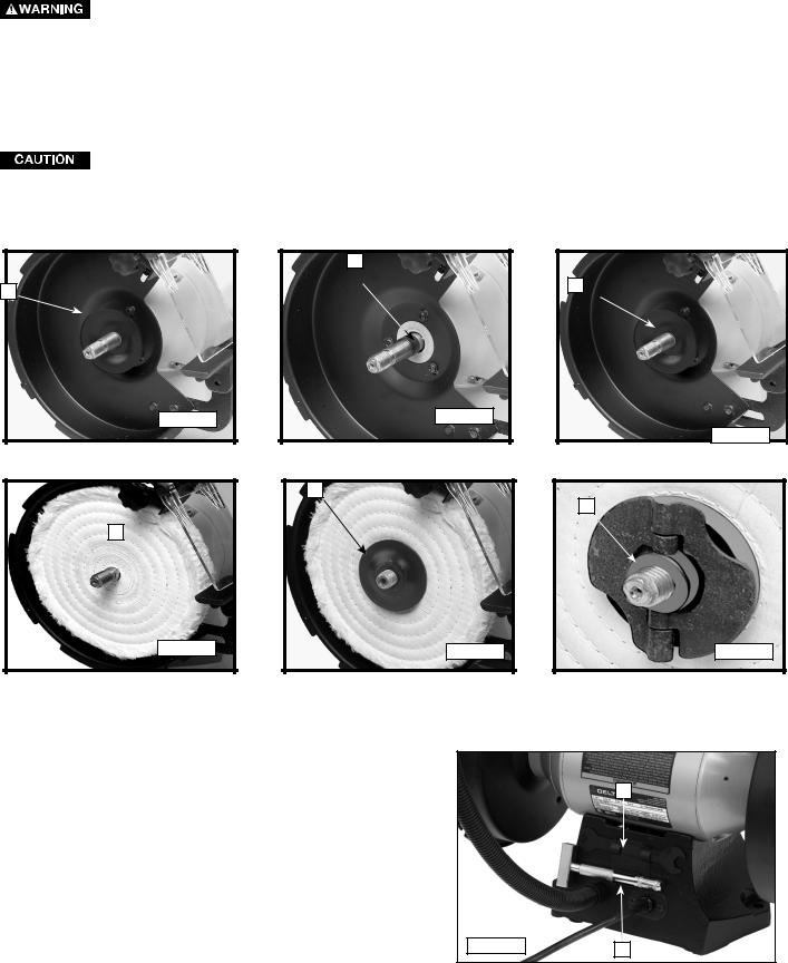
INSTALLING BUFFING WHEEL
Disconnect machine from power source.
1.Remove one grinding wheel as instructed in the section “CHANGING GRINDING WHEELS.”
2.Remove the inner wheel flange (A) Fig. 16.
3.Place the buffing wheel bushing (B) Fig. 17 on the shaft.
4.Replace the inner wheel flange (C) Fig. 18 on the shaft.
5.Place the buffing wheel (D) Fig. 19 on the shaft.
6.Place the other wheel flange (E) Fig. 20 on the shaft.
7.Thread the arbor nut (F) Fig. 21 on the arbor until the arbor nut makes contact with the arbor flange.
8.Push the arbor nut wings out to the closed position, flat against the arbor flange (Fig. 21).
The arbor nut wings must contact the arbor flange to prevent vibration.
9.Replace the wheel cover that was removed in step 2.
10.Adjust the spark guard and tool rest.
|
B |
A |
C |
|
|
Fig. 16 |
Fig. 17 |
|
Fig. 18 |
|
E |
|
F |
D |
|
Fig. 19 |
Fig. 20 |
Fig. 21 |
WRENCH STORAGE
Store the open end wrench (A) and the wheel dressing wrench (B) in the holder at the rear of the grinder (Fig. 22.)
A
Fig. 22 |
B |
13

TROUBLESHOOTING
For assistance with your machine, visit our website at www.deltaportercable.com for a list of service centers or call the DELTA Machinery help line at 1-800-223-7278 (In Canada call 1-800-463-3582).
MAINTENANCE
KEEP MACHINE CLEAN
Periodically blow out all air passages with dry compressed air. All plastic parts should be cleaned with a soft damp cloth. NEVER use solvents to clean plastic parts. They could possibly dissolve or otherwise damage the material.
 Wear certified safety equipment for eye, hearing and respiratory protection while using compressed air.
FAILURE TO START
Should your machine fail to start, check to make sure the prongs on the cord plug are making good contact in the outlet. Also, check for blown fuses or open circuit breakers in the line.
LUBRICATION & RUST PROTECTION
Apply household floor paste wax to the machine table, extension table or other work surface weekly. Or use a commercially available protective product designed for this purpose. Follow the manufacturer’s instructions for use and safety.
To clean cast iron tables of rust, you will need the following materials: a sheet of medium Scotch-Brite™ Blending Hand Pad, a can of WD-40® and a can of degreaser. Apply the WD-40 and polish the table surface with the Scotch-Brite pad. Degrease the table, then apply the protective product as described above.
ACCESSORIES
A complete line of accessories is available from your Delta Supplier, Porter-Cable • Delta Factory Service Centers, and Delta Authorized Service Stations. Please visit our Web Site www.deltaportercable.com for a catalog or for the name of your nearest supplier.


 Since accessories other than those offered by Delta have not been tested with this product, use of such accessories could be hazardous. For safest operation, only Delta recommended accessories should be used with this product.
SERVICE
REPLACEMENT PARTS
Use only identical replacement parts. For a parts list or to order parts, visit our website at servicenet.deltamachinery.com. You can also order parts from your nearest factory-owned branch, or by calling our Customer Care Center at 1-800-223-7278 to receive personalized support from highly-trained technicians.
SERVICE AND REPAIRS
All quality tools will eventually require servicing and/or replacement of parts. For information about Delta Machinery, its factoryowned branches, or an Authorized Warranty Service Center, visit our website at www.deltaportercable.com or call our Customer Care Center at 1-800-223-7278. All repairs made by our service centers are fully guaranteed against defective material and workmanship. We cannot guarantee repairs made or attempted by others.
You can also write to us for information at Delta Machinery, 4825 Highway 45 North, Jackson, Tennessee 38305 - Attention: Product Service. Be sure to include all of the information shown on the nameplate of your tool (model number, type, serial number, etc.)
14
 Loading...