


 PLC
PLC
PLC
DVP-PLC Application Manual
Programming
Table of Contents
Chapter 1 Basic Principles of PLC Ladder Diagram
Foreword: Background and Functions of PLC.......................................................... |
1 |
-1 |
|
1.1 |
The Working Principles of Ladder Diagram ........................................................ |
1 |
-1 |
1.2 |
Differences Between Traditional Ladder Diagram and PLC Ladder Diagram ........ |
1 |
-2 |
1.3 |
Edition Explanation of Ladder Diagram ............................................................. |
1 |
-3 |
1.4 |
How to Edit Ladder Diagram ............................................................................. |
1-8 |
|
1.5 |
The Conversion of PLC Command and Each Diagram Structure ......................... |
1 |
-12 |
1.6 |
Simplified Ladder Diagram ............................................................................... |
1 |
-15 |
1.7 |
Basic Program Designing Examples.................................................................. |
1 |
-17 |
Chapter 2 Functions of Devices in DVP-PLC
2.1 All Devices in DVP-PLC.................................................................................... |
2 |
-1 |
|
2.2 |
Values, Constants [K] / [H] ............................................................................... |
2 |
-6 |
2.3 |
Numbering and Functions of External Input/Output Contacts [X] / [Y].................. |
2 |
-8 |
2.4 |
Numbering and Functions of Auxiliary Relays [M] .............................................. |
2 |
-11 |
2.5 |
Numbering and Functions of Step Relays [S] ..................................................... |
2 |
-11 |
2.6 |
Numbering and Functions of Timers [T] ............................................................. |
2-12 |
|
2.7 |
Numbering and Functions of Counters [C] ......................................................... |
2-14 |
|
2.8 |
Numbering and Functions of Registers [D], [E], [F] ............................................ |
2 |
-28 |
2.8.1 Data register [D] ........................................................................................ |
2 |
-28 |
|
2.8.2 Index Register [E], [F] ................................................................................ |
2 |
-29 |
|
2.8.3 Functions and Features of File Registers .................................................... |
2-30 |
||
2.9 |
Pointer [N], Pointer [P], Interruption Pointer [I] .................................................. |
2-30 |
|
2.10 Special Auxiliary Relays and Special Data Registers ........................................ |
2 |
-33 |
|
2.11 Functions of Special Auxiliary Relays and Special Registers............................. |
2 |
-69 |
|
2.12 Error Codes ................................................................................................... |
2 |
-125 |
|
Chapter 3 Basic Instructions
3.1 |
Basic Instructions and Step Ladder Instructions ................................................ |
3-1 |
3.2 |
Explanations on Basic Instructions ................................................................... |
3-3 |
Chapter 4 Step Ladder Instructions
4.1 |
Step Ladder Instructions [STL], [RET] ............................................................... |
4 |
-1 |
4.2 |
Sequential Function Chart (SFC) ...................................................................... |
4 |
-2 |
4.3 |
How does a Step Ladder Instruction Work? ....................................................... |
4 |
-3 |
4.4 |
Things to Note for Designing a Step Ladder Program......................................... |
4 |
-7 |
4.5 |
Types of Sequences ......................................................................................... |
4-9 |
|
4.6 |
IST Instruction ................................................................................................. |
4 |
-17 |
Chapter 5 Categories & Use of Application Instructions
5.1 |
List of Instructions ........................................................................................... |
5-1 |
|
5.2 |
Composition of Application Instruction .............................................................. |
5 |
-6 |
5.3 |
Handling of Numeric Values.............................................................................. |
5 |
-11 |
5.4 |
E, F Index Register Modification ....................................................................... |
5 |
-14 |
5.5 |
Instruction Index .............................................................................................. |
5-16 |
|
Chapter 6 Application Instructions API 00-49
● |
API00 09 Loop Control .......................................................................... |
6 |
-1 |
|
● |
API10 19 |
Transmission Comparison ....................................................... |
6-18 |
|
● |
API20 29 |
Four Arithmetic Operation ....................................................... |
6-32 |
|
● |
API30 39 |
Rotation & Displacement......................................................... |
6 |
-46 |
● |
API40 49 |
Data Processing ..................................................................... |
6 |
-57 |
Chapter 7 Application Instructions API 50-99
● |
API50 59 |
High Speed Processing........................................................... |
7 |
-1 |
● |
API60 69 |
Handy Instructions.................................................................. |
7 |
-39 |
● |
API70 79 |
Display of External Settings .................................................... |
7-59 |
|
● |
API80 88 |
Serial I/O ............................................................................... |
7 |
-80 |
Chapter 8 Application Instructions API 100-149
● |
API100 109 |
Communication ................................................................... |
8-1 |
● |
API110 119 Floating Point Operation ...................................................... |
8-23 |
|
● |
API120 129 |
Floating Point Operation ..................................................... |
8-31 |
● |
API130 139 |
Floating Point Operatio ....................................................... |
8-43 |
● |
API140 149 |
Others ................................................................................ |
8-55 |
Chapter 9 Application Instructions API 150-199
● |
API150 154 |
Others ................................................................................ |
9-1 |
● |
API155 159 |
Position Control .................................................................. |
9-14 |
● |
API160 169 Real Time Calendar ............................................................ |
9-39 |
|
● |
API170 171 |
Gray Code Conversion ........................................................ |
9-49 |
● |
API172 175 |
Floating Point Operation ..................................................... |
9-51 |
● |
API180 190 |
Matrix................................................................................. |
9-59 |
● |
API191 199 |
Positioning Instruction ........................................................ |
9-76 |
Chapter 10 Application Instructions API 215-246
● |
API202 203 |
Others................................................................................ |
10 |
-1 |
● |
API215 223 |
Contact Type Logic Operation Instruction............................. |
10-7 |
|
● |
API224 246 |
Contact Type Compare Instruction ....................................... |
10 |
-10 |

1 Basic Principles of PLC Ladder Diagram
Foreword: Background and Functions of PLC
PLC (Programmable Logic Controller) is an electronic device, previously called “sequence controller”. In 1978, NEMA (National Electrical Manufacture Association) in the United States officially named it as “programmable logic controller”. PLC reads the status of the external input devices, e.g. keypad, sensor, switch and pulses, and execute by the microprocessor logic, sequential, timing, counting and arithmetic operations according the status of the input signals as well as the pre-written program stored in the PLC. The generated output signals are sent to output devices as the switch of a relay, electromagnetic valve, motor drive, control of a machine or operation of a procedure for the purpose of machine automation or processing procedure. The peripheral devices (e.g. personal computer/handheld programming panel) can easily edit or modify the program and monitor the device and conduct on-site program maintenance and adjustment. The widely used language in designing a PLC program is the ladder diagram.
With the development of the electronic technology and wider applications of PLC in the industry, for example in position control and the network function of PLC, the input/output signals of PLC include DI (digital input), AI (analog input), PI (pulse input), NI (numeric input), DO (digital output), AO (analog output), and PO (pulse output). Therefore, PLC will still stand important in the industrial automation field in the future.
1.1The Working Principles of Ladder Diagram
The ladder diagram was a diagram language for automation developed in the WWII period, which is the oldest and most widely adopted language in automation. In the initial stage, there were only A (normally open) contact, B (normally closed) contact, output coil, timer and counter…the sort of basic devices on the ladder diagram (see the power panel that is still used today). After the invention of PLC, the devices displayable on the ladder diagram are added with differential contact, latched coil and the application commands which were not in a traditional power panel, for example the addition, subtraction, multiplication and division operations.
The working principles of the traditional ladder diagram and PLC ladder diagram are basically the same. The only difference is that the symbols on the traditional ladder diagram are more similar to its original form, and PLC ladder diagram adopts the symbols that are easy to recognize and shown on computer or data sheets. In terms of the logic of the ladder diagram, there are combination logic and sequential logic.
1.Combination Logic
Examples of traditional ladder diagram and PLC ladder diagram for combination logic:
Traditional Ladder Diagram |
PLC Ladder Diagram |
|||
X0 |
|
Y0 |
X0 |
|
|
|
|
Y0 |
|
X1 |
|
|
|
|
|
Y1 |
X1 |
Y1 |
|
|
|
|
|
|
X2 |
X4 |
Y2 |
X2 |
X4 |
|
Y2 |
|||
|
|
|
|
|
X3 |
|
|
X3 |
|
|
|
|
|
|
Row 1: Using a normally open (NO) switch X0 (“A” switch or “A" contact). When X0 is not pressed, the contact will be open loop (Off), so Y0 will be Off. When X0 is pressed, the contact will be On, so Y0 will be On.
DVP-PLC Application Manual |
1-1 |

1 Basic Principles of PLC Ladder Diagram
Row 2: Using a normally closed (NC) switch X1 (“B” switch or “B” contact). When X1 is not pressed, the contact will be On, so Y1 will be On. When X1 is pressed, the contact will be open loop (Off), so Y1 will be Off.
Row 3: The combination logic of more than one input devices. Output Y2 will be On when X2 is not pressed or X3 and X4 are pressed.
2.Sequential Logic
Sequential logic is a circuit with "draw back” structure, i.e. the output result of the circuit will be drawn back as an input criterion. Therefore, under the same input criteria, different previous status or action sequence will follow by different output results.
Examples of traditional ladder diagram and PLC ladder diagram for sequential logic:
Traditional Ladder Diagram |
PLC Ladder Diagram |
|||||||||||||||||
|
|
X5 |
|
X6 |
|
Y3 |
|
X5 |
X6 |
|||||||||
|
|
|
|
|
||||||||||||||
|
|
|
|
|
|
|
|
|
|
|
|
|
|
|
|
|
|
Y3 |
|
|
|
|
|
|
|
|
|
|
|
|
|
|
|
|
|
|
|
|
|
Y3 |
|
|
|
|
|
|
Y3 |
|
|
|
|
|||||
|
|
|
|
|
|
|
|
|
|
|
|
|
|
|
|
|
|
|
|
|
|
|
|
|
|
|
|
|
|
|
|
|
|
|
|
|
|
|
|
|
|
|
|
|
|
|
|
|
|
|
|
|
|
|
|
|
|
|
|
|
|
|
|
|
|
|
|
|
|
|
|
|
|
|
|
When the circuit is first connected to the power, though X6 is On, X5 is Off, so Y3 will be Off. After X5 is pressed, Y3 will be On. Once Y3 is On, even X5 is released (Off), Y3 can still keep its action because of the draw back (i.e.
the self-retained circuit). The actions are illustrated in the table below. |
|
|||
|
|
|
|
|
Device status |
X5 |
X6 |
Y3 |
|
Action sequence |
||||
|
|
|
||
1 |
No action |
No action |
Off |
|
2 |
Action |
No action |
On |
|
|
|
|
|
|
3 |
No action |
No action |
On |
|
4 |
No action |
Action |
Off |
|
|
|
|
|
|
5 |
No action |
No action |
Off |
|
|
|
|
|
|
From the table above, we can see that in different sequence, the same input status can result in different output results. For example, switch X5 and X6 of action sequence 1 and 3 do not act, but Y3 is Off in sequence 1 and On in sequence 3. Y3 output status will then be drawn back as input (the so-called “draw back”), making the circuit being able to perform sequential control, which is the main feature of the ladder diagram circuit. Here we only explain contact A, contact B and the output coil. Other devices are applicable to the same method. See Chapter 3 “Basic instructions” for more details.
1.2 Differences Between Traditional Ladder Diagram and PLC Ladder Diagram
Though the principles of traditional ladder diagram and PLC ladder diagram are the same, in fact, PLC adopts microcomputer to simulate the motions of the traditional ladder diagram, i.e. scan-check status of all the input devices and output coil and calculate to generate the same output results as those from the traditional ladder diagram based on the logics of the ladder diagram. Due to that there is only one microcomputer, we can only check the program of the ladder diagram one by one and calculate the output results according to the program and the I/O status before the cyclic process of sending the results to the output interface Æ re-reading of the input status Æ calculation Æ output. The time spent in the cyclic process is called the “scan time” and the time can be longer with the expansion of the program. The scan time can cause delay from the input detection to output response of the PLC. The longer the delay,
1-2 |
DVP-PLC Application Manual |

1 Basic Principles of PLC Ladder Diagram
the bigger the error is to the control. The control may even be out of control. In this case, you have to choose a PLC with faster scan speed. Therefore, the scan speed is an important specification requirement in a PLC. Owing to the advancement in microcomputer and ASIC (IC for special purpose), there has been great improvement in the scan speed of PLC nowadays. See the figure below for the scan of the PLC ladder diagram program.
The output result is calculated based on the ladder diagram. (The result has not yet sent to the external output point, but the internal device will perform an immediate output.)
Read input status from outside |
|
|||||||||||||
|
X0 |
|
|
X1 |
|
|
|
|
|
|
||||
|
|
|
|
|
|
|
|
|
||||||
Start |
|
|
|
|
|
|
|
|
|
|
|
|
Y0 |
|
|
|
|
|
|
|
|
|
|
|
|
|
|||
|
Y0 |
|
|
|
|
|
|
|
|
|
|
|
||
|
|
|
|
X3 |
X10 |
|
||||||||
|
|
|
|
|
||||||||||
|
|
|
|
|
||||||||||
|
M100 |
Executing in cycles |
||||||||||||
|
|
|
|
|
|
|
|
|
|
|
|
|
Y1 |
|
|
|
|
|
|
|
|
|
|
|
|
|
|
|
|
|
|
|
|
: |
|
|
|
|
|
|
|
|
|
|
|
|
|
|
: |
|
|
|
|
|
|
|
|
|
|
|
X100 M505 |
|
|
|
|
|
|
|||||||
|
|
|
|
|
|
|
|
|
|
|
|
|
Y126 |
|
|
|
|
|
|
|
|
|
|
|
|
|
|
|
|
|
|
|
|
|
|
|
|
|
|
|
|
|
|
|
|
|
|
|
|
|
|
|
|
|
|
|
|
End |
|
|
|
|
|
|
|
|
|
|
|
|||||
Send the result to the output point |
|
|||||||||||||
Besides the difference in the scan time, PLC ladder and traditional ladder diagram also differ in “reverse current”. For example, in the traditional ladder diagram illustrated below, when X0, X1, X4 and X6 are On and others are Off, Y0 output on the circuit will be On as the dotted line goes. However, the PLC ladder diagram program is scanned from up to down and left to right. Under the same input circumstances, the PLC ladder diagram editing tool WPLSoft will be able to detect the errors occurring in the ladder diagram.
Reverse current of traditional ladder diagram |
Reverse current of PLC ladder diagram |
||||||||||||||||||||||||||||||||||||||||
|
X0 |
|
|
|
X1 |
X2 |
Y0 |
|
|
|
|
X0 |
|
|
X1 |
X2 |
Y0 |
||||||||||||||||||||||||
|
|
|
|||||||||||||||||||||||||||||||||||||||
|
|
|
|
|
|
|
|
|
|
|
|
|
|
|
|
|
|
|
|
|
|
|
|
|
|
|
|
|
|
|
|
|
|
|
|
|
|
|
|
|
Y0 |
|
|
X3 |
|
|
|
|
|
|
X4 |
|
X5 |
|
|
|
|
|
|
|
|
|
|
|
|
|
|
|
|
|
|
|
|
|
|||||||||
|
|
a |
|
|
|
b |
|
|
|
|
|
|
|
|
X3 a |
|
|
|
X4 |
b |
|
X5 |
|
|
|||||||||||||||||
|
|
|
|
|
|
|
|
|
|
|
|
|
|
|
|
|
|
|
|
|
|
|
|
|
|
|
|
|
|
|
|||||||||||
|
|
|
|
|
|
|
|
|
|
|
|
|
|
|
|
|
|
|
|
|
|
|
|||||||||||||||||||
|
|
|
|
|
|
|
X6 |
|
|
|
|
|
|
|
|
|
|
|
|
|
|
|
|
|
|
|
|
|
|
|
|
|
|
|
|
|
|
||||
|
|
|
|
|
|
|
|
|
|
|
|
|
|
|
|
|
|
|
|
|
|
|
|
|
X6 |
|
|
|
|
|
|
||||||||||
|
|
|
|
|
|
|
|
|
|
|
|
|
|
|
|
|
|
|
|
|
|
|
|
|
|
|
|
|
|
|
|||||||||||
|
|
|
|
|
|
|
|
|
|
|
|
|
|
|
|
|
|
|
|
|
|
|
|
|
|
|
|
|
|
|
|
|
|
|
|
|
|
|
|
|
|
|
|
|
|
|
|
|
|
|
|
|
|
|
|
|
|
|
|
|
|
|
|
|
|
|
|
|
|
|
|
|
|
|
|
|
|
|
|
|
|
|
|
|
|
|
|
|
|
|
|
|
|
|
|
|
|
|
|
|
|
|
|
|
|
|
|
|
|
|
|
|
|
|
|
|
|
|
|
|
|
|
|
|
|
Error detected in the third row
1.3How to Edit Ladder Diagram
Ladder diagram is a diagram language frequently applied in automation. The ladder diagram is composed of the symbols of electric control circuit. The completion of the ladder diagram by the ladder diagram editor is the completion of the PLC program design. The control flow illustrated by diagram makes the flow more straightforward and acceptable for the technicians of who are familiar with the electric control circuit. Many basic symbols and actions in
DVP-PLC Application Manual |
1-3 |

1 Basic Principles of PLC Ladder Diagram
the ladder diagram come from the frequently-seen electromechanical devices, e.g. buttons, switches, relay, timer and counter, etc. in the traditional power panel for automation control.
Internal devices in the PLC: The types and quantity of the devices in the PLC vary in different brand names. Though the internal devices in the PLC adopts the names, e.g. transistor, coil, contact and so on, in the traditional electric control circuit, these physical devices do not actually exist inside the PLC. There are only the corresponding basic units (1 bit) inside the memory of the PLC. When the bit is “1”, the coil will be On, and when the bit is “0”, the coil will be Off. The normally open contact (NO or contact A) directly reads the value of the corresponding bit. The normally close contact (NC or contact B) reads the opposite state of the value of the corresponding bit. Many relays will occupy many bits. 8 bits equal a “byte”. 2 bytes construct a “word” and 2 words combined is “double word”. Byte, word or double words are used when many relays are processed (e.g. addition/subtraction, displacement) at the same time. The other two devices, timer and counter, in the PLC have coil, timer value and counter value and they have to process some values in byte, word or double word.
All kinds of internal devices in the value storage area in the PLC occupy their fixed amount of storage units. When you use these devices, you are actually read the contents stored in the form of bit, byte or word.
Introductions on the basic internal devices in the PLC (See Ch 2. Functions of Devices in DVP-PLC for more details.)
Device |
Functions |
|
|
|
The input relay is an internal memory (storage) unit in the PLC corresponding to a external |
|
input point and is used for connecting to the external input switches and receiving external |
|
input signals. The input relay will be driven by the external input signals which make it “0” or |
|
“1". Program designing cannot modify the status of the relay, i.e. it cannot re-write the basic |
|
unit of a relay, nor can it force On/Off of the relay by HPP/WPLSoft. SA/SX/SC/EH/EH2/SV |
|
series MPU can simulate input relay X and force On/Off of the relay. But the status of the |
Input relay |
external input points will be updated and disabled, i.e. the external input signals will not be read |
|
into their corresponding memories inside PLC, but only the input points on the MPU. The input |
|
points on the extension modules will still operate normally. There are no limitations on the times |
|
of using contact A and contact B of the input relay. The input relays without corresponding input |
|
signals can only be left unused and cannot be used for other purposes. |
|
& Device indication: X0, X1,…X7, X10, X11,… are indicated as X and numbered in octal |
|
form. The No. of input points are marked on MPU and extension modules. |
|
The output relay is an internal memory (storage) unit in the PLC corresponding to a external |
|
output point and is used for connecting to the external load. The output relay will be driven by |
|
the contact of an input relay, contacts of other internal devices and the contacts on itself. A |
|
normally open contact of the output relay is connected to the external load. Same as the input |
Output relay |
contacts, there are no limitations on the times of using other contacts of the output relay. The |
|
output relay without corresponding output signals can only be left unused and can be used as |
|
input relay if necessary. |
|
& Device indication: Y0, Y1,…Y7, Y10, Y11,…are indicated as Y and numbered in octal |
|
form. The No. of output points are marked on MPU and extension modules. |
1-4 |
DVP-PLC Application Manual |

1 Basic Principles of PLC Ladder Diagram
Internal relay
Step
Timer
Counter
Data register
The internal relay does not have connection with the external. It is an auxiliary relay inside the PLC with the functions same as those of the auxiliary (middle) relay in the electric control circuit. Every internal relay corresponds to a basic internal storage unit and can be driven by the contacts of the input relay, contacts of the output relay and the contacts of other internal devices. There are no limitations on the times of using the contacts of the internal relay and there will be no output from the internal relay, but from the output point.
&Device indication: M0, M1,…, M4095 are indicated as M and numbered in decimal form.
DVP series PLC offers a step-type control program input method. STL instruction controls the transfer of step S, which makes it easy for the writing of the control program. If you do not use any step program in the control program, step S can be used as a internal relay M as well as an alarm point.
&Device indication: S0, S1,…S1023 are indicated as S and numbered in decimal form.
The timer is used for timing and has coil, contact and register in it. When the coil is On and the estimated time is reached, its contact will be enabled (contact A closed, contact B open). Every timer has its fixed timing period (unit: 1ms/10ms/100ms). Once the coil is Off, the contact iwlwl be disabled (contact A open, contact B closed) and the present value on the timer will become “0”.
&Device indication: T0, T1,…,T255 are indicated as T and numbered in decimal form. Different No. refers to different timing period.
The counter is used for counting. Before using the counter, you have to give the counter a set value (i.e. the number of pulses for counting). There are coil, contact and registers in the counter. When the coil goes from Off to On, the counter will regard it as an input of 1 pulse and the present value on the counter will plus “1”. We offer 16-bit and 32-bit high-speed counters for our users.
&Device indication: C0, C1,…,C255 are indicated as C and numbered in decimal form.
Data processing and value operations always occur when the PLC conducts all kinds of sequential control, timing and counting. The data register is used for storing the values or all kinds of parameters. Every register is able to store a word (16-bit binary value). Double words will occupy 2 adjacent data registers.
&Device indication: D0, D1,…,D9,999 are indicated as D and numbered in decimal form.
DVP-PLC Application Manual |
1-5 |

1 Basic Principles of PLC Ladder Diagram
The file register is used for storing the data or all kinds of parameters when the data registers required for processing the data and value operations are insufficient. Every file register is able to store a 16-bit word. Double words will occupy 2 adjacent file registers. In SA/SX/SC series
MPU, there are 1,600 file registers. In EH/EH2/SV series MPU, there are 10,000 file registers.
File register
There is not an actual device No. for a file register. The reading and writing of file registers should be executed by instructions API 148 MEMR, API 149 MEMW, or through the peripheral device HPP02 and WPLSoft.
&Device indication: K0 ~ K9,999, numbered in decimal form.
E and F index registers are 16-bit data registers as other data registers. They can be read and
written and can be used in word devices, bit devices or as a constant for index indication.
Index register
&Device indication: E0 ~ E7, F0 ~ F7 are indicated as E and F and numbered in decimal form.
The structure of a ladder diagram:
|
|
|
|
Structure |
Explanation |
|
Instruction |
|||||||
|
|
|
|
|
|
|
|
|
|
|
|
|
|
|
|
|
|
|
|
|
|
|
|
|
|
|
Normally open, contact A |
|
LD |
|
|
|
|
|
|
|
|
|
|
|
|
|
||
|
|
|
|
|
|
|
|
|
|
|
|
|
||
|
|
|
|
|
|
|
|
|
|
|
|
|
||
|
|
|
|
|
|
|
|
|
|
|
|
|
|
|
|
|
|
|
|
|
|
|
|
|
|
|
|
|
|
|
|
|
|
|
|
|
|
|
|
|
|
Normally closed, contact B |
|
LDI |
|
|
|
|
|
|
|
|
|
|
|
|
|
||
|
|
|
|
|
|
|
|
|
|
|
|
|
||
|
|
|
|
|
|
|
|
|
|
|
|
|
||
|
|
|
|
|
|
|
|
|
|
|
|
|
|
|
|
|
|
|
|
|
|
|
|
|
|
|
|
|
|
|
|
|
|
|
|
|
|
|
|
|
|
Normally open in series |
|
AND |
|
|
|
|
|
|
|
|
|
|
|
|
|
||
|
|
|
|
|
|
|
|
|
|
|
|
|
||
|
|
|
|
|
|
|
|
|
|
|
|
connection |
|
|
|
|
|
|
|
|
|
|
|
|
|
|
|
|
|
|
|
|
|
|
|
|
|
|
|
|
|
|
|
|
|
|
|
|
|
|
|
|
|
|
|
|
Normally closed in series |
|
ANI |
|
|
|
|
|
|
|
|
|
|
|
|
|
||
|
|
|
|
|
|
|
|
|
|
|
|
|
||
|
|
|
|
|
|
|
|
|
|
|
|
connection |
|
|
|
|
|
|
|
|
|
|
|
|
|
|
|
|
|
|
|
|
|
|
|
|
|
|
|
|
|
|
|
|
|
|
|
|
|
|
|
|
|
|
|
|
Normally open in parallel |
|
OR |
|
|
|
|
|
|
|
|
|
|
|
|
|
||
|
|
|
|
|
|
|
|
|
|
|
|
|
||
|
|
|
|
|
|
|
|
|
|
|
|
|
||
|
|
|
|
|
|
|
|
|
|
|
|
connection |
|
|
|
|
|
|
|
|
|
|
|
|
|
|
|
|
|
|
|
|
|
|
|
|
|
|
|
|
|
|
|
|
|
|
|
|
|
|
|
|
|
|
|
|
Normally closed in parallel |
|
ORI |
|
|
|
|
|
|
|
|
|
|
|
|
|
||
|
|
|
|
|
|
|
|
|
|
|
|
|
||
|
|
|
|
|
|
|
|
|
|
|
|
|
||
|
|
|
|
|
|
|
|
|
|
|
|
connection |
|
|
|
|
|
|
|
|
|
|
|
|
|
|
|
|
|
|
|
|
|
|
|
|
|
|
|
|
|
|
|
|
|
|
|
|
|
|
|
|
|
|
|
|
|
|
|
|
|
|
|
|
|
|
|
|
|
|
|
Rising-edge trigger switch |
|
LDP |
|
|
|
|
|
|
|
|
|
|
|
|
|
||
|
|
|
|
|
|
|
|
|
|
|
|
|
||
|
|
|
|
|
|
|
|
|
|
|
|
|
||
|
|
|
|
|
|
|
|
|
|
|
|
|
|
|
|
|
|
|
|
|
|
|
|
|
|
|
|
|
|
|
|
|
|
|
|
|
|
|
|
|
|
Falling-edge trigger switch |
|
LDF |
|
|
|
|
|
|
|
|
|
|
|
|
|
||
|
|
|
|
|
|
|
|
|
|
|
|
|
||
|
|
|
|
|
|
|
|
|
|
|
|
|
||
|
|
|
|
|
|
|
|
|
|
|
|
|
|
|
|
|
|
|
|
|
|
|
|
|
|
|
|
|
|
|
|
|
|
|
|
|
|
|
|
|
|
Rising-edge trigger in series |
|
ANDP |
|
|
|
|
|
|
|
|
|
|
|
|
|
||
|
|
|
|
|
|
|
|
|
|
|
|
|
||
|
|
|
|
|
|
|
|
|
|
|
|
connection |
|
|
|
|
|
|
|
|
|
|
|
|
|
|
|
|
|
|
|
|
|
|
|
|
|
|
|
|
|
|
|
|
|
|
|
|
|
|
|
|
|
|
|
|
Falling-edge trigger in series |
|
ANDF |
|
|
|
|
|
|
|
|
|
|
|
|
|
||
|
|
|
|
|
|
|
|
|
|
|
|
|
||
|
|
|
|
|
|
|
|
|
|
|
|
connection |
|
|
|
|
|
|
|
|
|
|
|
|
|
|
|
|
|
|
|
|
|
|
|
|
|
|
|
|
|
|
|
|
|
|
|
|
|
|
|
|
|
|
|
|
Rising-edge trigger in parallel |
|
ORP |
|
|
|
|
|
|
|
|
|
|
|
|
|
||
|
|
|
|
|
|
|
|
|
|
|
|
|
||
|
|
|
|
|
|
|
|
|
|
|
|
|
||
|
|
|
|
|
|
|
|
|
|
|
|
connection |
|
|
|
|
|
|
|
|
|
|
|
|
|
|
|
|
|
|
|
|
|
|
|
|
|
|
|
|
|
|
|
|
|
|
|
|
|
|
|
|
|
|
|
|
Falling-edge trigger in parallel |
|
ORF |
|
|
|
|
|
|
|
|
|
|
|
|
|
||
|
|
|
|
|
|
|
|
|
|
|
|
|
||
|
|
|
|
|
|
|
|
|
|
|
|
|
||
|
|
|
|
|
|
|
|
|
|
|
|
connection |
|
|
|
|
|
|
|
|
|
|
|
|
|
|
|
|
|
|
|
|
|
|
|
|
|
|
|
|
|
|
|
|
|
|
|
|
|
|
|
|
|
|
|
|
|
|
|
Devices Used
X, Y, M, S, T, C X, Y, M, S, T, C X, Y, M, S, T, C X, Y, M, S, T, C
X, Y, M, S, T, C
X, Y, M, S, T, C
X, Y, M, S, T, C X, Y, M, S, T, C X, Y, M, S, T, C X, Y, M, S, T, C
X, Y, M, S, T, C
X, Y, M, S, T, C
|
|
|
|
|
|
|
|
Block in series connection |
ANB |
- |
|
|
|
|
|
|
|
|
|||
|
|
|
|
|
|
|
|
|||
|
|
|
|
|
|
|||||
|
|
|
|
|
|
|
|
|
|
|
|
|
|
|
|
|
|
|
|
|
|
|
|
|
|
|
|
|
|
Block in parallel connection |
ORB |
- |
|
|
|
|
|
|
|
|
|||
|
|
|
|
|
|
|
|
|||
|
|
|
|
|
|
|
|
|||
|
|
|
|
|
|
|
|
|
|
|
|
|
|
|
|
|
|
|
|
|
|
|
|
|
|
|
|
|
|
|
|
|
1-6 |
DVP-PLC Application Manual |
1 Basic Principles of PLC Ladder Diagram
|
|
|
Structure |
Explanation |
Instruction |
||||||
|
|
|
|
|
|
|
|
|
|
|
|
|
|
|
|
|
|
|
|
|
|
|
MPS |
|
|
|
|
|
|
|
|
|
|
|
|
|
|
|
|
|
|
|
|
|
|
|
|
|
|
|
|
|
|
|
|
|
|
|
|
|
|
|
|
|
|
|
|
|
|
Multiple output |
MRD |
|
|
|
|
|
|
|
|
|
|
||
|
|
|
|
|
|
|
|
|
|
||
|
|
|
|
|
|
|
|
|
|
|
MPP |
|
|
|
|
|
|
|
|
|
|
|
|
|
|
|
|
|
|
|
|
|
|
|
|
|
|
|
|
|
|
|
|
|
|
|
|
|
|
|
|
|
|
|
|
|
|
Coil driven output instruction |
OUT |
|
|
|
|
|
|
|
|
|
|||
|
|
S |
|
|
|
|
|
|
Step ladder |
STL |
|
|
|
|
|
|
|
||||||
|
|
|
|
||||||||
|
|
|
|
|
|
|
|
|
|
|
|
|
|
|
|
|
|
|
|
|
|
Basic instruction |
Application |
|
|
|
|
|
|
|
|
|
|
||
|
|
|
|
|
|
|
|
|
|
Application instruction |
instructions |
|
|
|
|
|
|
|
|
|
|
||
|
|
|
|
|
|
|
|
|
|
|
|
|
|
|
|
|
|
|
|
|
|
Inverse logic |
INV |
|
|
|
|
|
|
|
|
|
|
||
|
|
|
|
|
|
|
|
|
|
|
|
Devices Used
-
Y, M, S
S
See Ch.3 for basic instructions (RST/SET and CNT/TMR) and Ch.5 ~ 10 for application instructions
-
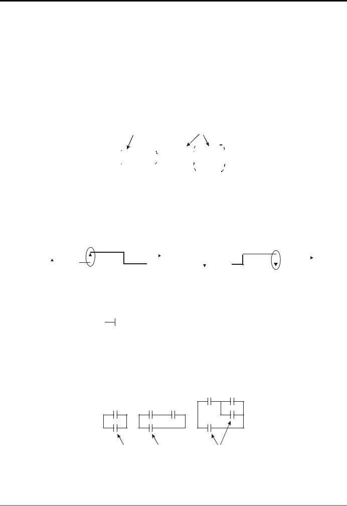
Block:
A block is a series or parallel operation composed of more than 2 devices. There are series block and parallel block.
Series block
Parallel block
Separation line and combination line:
The vertical line is used for separating the devices. For the devices on the left, the vertical line is a combination line, indicating that there are at least 2 rows of circuits on the left connected with the vertical line. For the devices on the right, the vertical line is a separation line, indicating that there are at least 2 rows of circuits interconnected on the right side of the vertical line).
1 2
Combination line for block 1 |
Combination line for block 2 |
Separation line for block 2 |
|
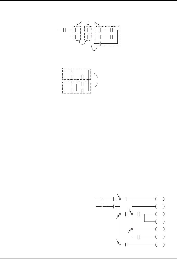
Network:
A complete block network is composed of devices and all kinds of blocks. The blocks or devices connectable by a vertical line or continuous line belong to the same network.
DVP-PLC Application Manual |
1-7 |

1 Basic Principles of PLC Ladder Diagram
Network 1
An independent network
Network 2
An incomplete network
1.4 How to Edit a PLC Ladder Diagram
The editing of the program should start from the left power line and ends at the right power line, a row after another. The drawing of the right power line will be omitted if edited from WPLSoft. A row can have maximum 11 contacts on it. If 11 is not enough, you can continuously connect more devices and the continuous number will be generated automatically. The same input points can be used repeatedly. See the figure below:
X0 X1 X2 X3 X4 X5 X6 X7 X10 C0 C1
|
|
|
|
|
|
|
|
|
|
|
|
|
|
|
|
|
|
|
|
|
|
|
|
00000 |
|
|
|
|
|
|
|
|
|
|
|
|
|
|
|
|
|
||||||||||
|
|
|
X11 X12 X13 |
||||||||||||||||||||||
00000 |
|
|
|
|
|
|
|
|
|
|
|
|
|
|
|
|
|
|
|
|
|
|
Y0 |
||
|
|
|
|
|
|
|
|
|
|
|
|
|
|
|
|
|
|
|
|
|
|
||||
Continuous number
The operation of the ladder diagram program is scanning from top left to bottom right. The coil and the operation frame of the application instruction belong to the output side in the program and are placed in the right if the ladder diagram. Take the figure below for example, we will step by step explain the process of a ladder diagram. The numbers in the black circles indicate the order.
|
X0 |
X1 |
|
|
Y1 |
X4 |
|
|
|||||||||||||
|
|
|
|
|
|||||||||||||||||
|
|
|
|
|
|
|
|
|
|
|
|
|
|
|
|
|
|
|
Y1 |
|
|
|
|
|
|
|
|
|
|
|
|
|
|
|
|
|
|
||||||
|
M0 |
|
|
|
|
|
T0 |
M3 |
|
T0 |
K10 |
||||||||||
|
|
|
|
M1 |
|
|
|
|
|
|
|
|
|
|
|
|
TMR |
||||
|
|
|
|
|
|
|
|
|
|
|
|
|
|
|
|
||||||
|
X3 |
|
|
|
|
|
|
|
|
|
|
|
|
|
|
|
|||||
|
|
|
|
|
|
|
|
|
|
|
|
|
|
|
|
|
|
|
|
|
|
|
|
|
|
|
|
|
|
|
|
|
|
|
|
|
|
|
|
|
|
|
|
|
|
|
|
|
|
|
|
|
|
|
|
|
|
|
|
|
|
|
|
|
|
The order of the instructions: |
|
|
1 |
LD |
X0 |
2 |
OR |
M0 |
3 |
AND |
X1 |
4 |
LD |
X3 |
|
AND |
M1 |
1-8 |
DVP-PLC Application Manual |
1 Basic Principles of PLC Ladder Diagram
|
ORB |
|
|
5 |
LD |
Y1 |
|
|
AND |
X4 |
|
6 |
LD |
T0 |
|
|
AND |
M3 |
|
|
ORB |
|
|
7 |
ANB |
|
|
8 |
OUT |
Y1 |
|
|
TMR |
T0 |
K10 |
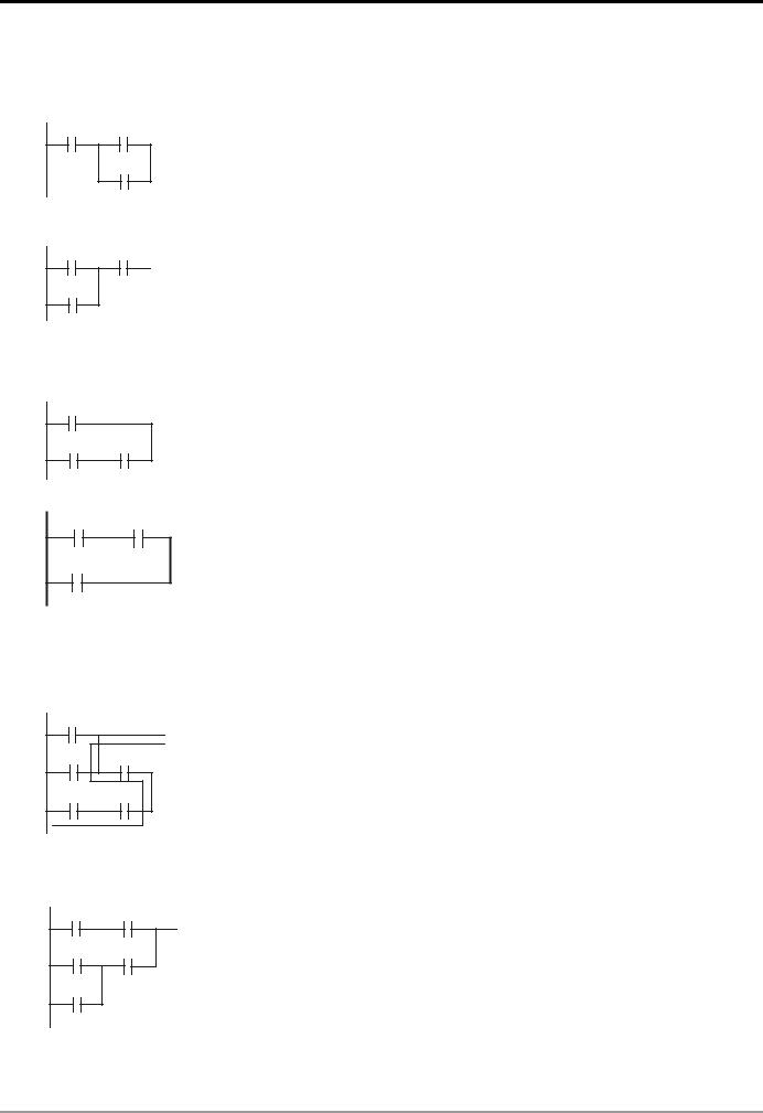
Explanations on the basic structures in the ladder diagram:
1. LD (LDI) instruction: Given in the start of a block.
|
|
|
|
|
|
LD instruction |
LD instruction |
|||||||||||||||||||||||||||||||||||||||||||||||
|
|
|
|
|
|
|
|
|
|
|
|
|
|
|
|
|
|
|
|
|
|
|
|
|
|
|
|
|
|
|
|
|
|
|
|
|
|
|
|
|
|
|
|
|
|
|
|
|
|
|
|
|
|
|
|
|
|
|
|
|
|
|
|
|
|
|
|
|
|
|
|
|
|
|
|
|
|
|
|
|
|
|
|
|
|
|
|
|
|
|
|
|
|
|
|
|
|
|
|
|
|
|
|
|
|
|
|
|
|
|
|
|
|
|
|
|
|
|
|
|
|
|
|
|
|
|
|
|
|
|
|
|
|
|
|
|
|
|
|
|
|
|
|
|
|
|
|
|
|
|
|
|
|
|
|
|
|
|
|
|
|
|
|
|
|
|
|
|
|
|
|
|
|
|
|
|
|
|
|
|
|
|
|
|
|
|
|
|
|
|
|
|
|
|
|
|
|
|
|
|
|
|
|
|
|
|
|
|
|
|
|
|
|
|
|
|
|
|
|
|
|
|
|
|
|
|
|
|
|
|
|
|
|
|
|
|
|
|
|
|
|
|
|
|
|
|
|
|
|
|
|
|
|
|
|
|
|
|
|
|
|
|
|
|
|
|
|
|
|
|
|
|
|
|
|
|
|
|
|
|
|
|
|
|
|
|
|
|
|
|
|
|
|
|
|
|
|
|
|
|
|
|
|
|
|
|
|
|
|
|
|
|
|
|
|
|
|
|
|
|
|
|
|
|
|
|
|
|
|
AND block |
OR block |
The structure of LDP and LDF instructions are the same as that of LD instruction, and the two only differ in their actions. LDP and LDF instructions only act at the rising edge or falling edge when the contact is On, as shown in the figure below.
|
|
|
|
|
Rising edge |
|
|
|
|
|
|
|
|
Falling edge |
|||||
|
|
|
|
|
|
|
|
|
|
|
|
|
|
|
|||||
X0 |
|
|
|
|
X0 |
|
|
|
|
||||||||||
|
|
|
|
|
|
|
|
Time |
|
|
|
|
|
|
|
|
Time |
||
|
|
|
|
|
OFF ON |
OFF |
|
|
|
|
|
|
|
OFF ON |
OFF |
||||
2. AND (ANI) instruction: A single device connects to another single device or a block in series
AND instruction |
AND instruction |
|||||||||
|
|
|
|
|
|
|
|
|
|
|
|
|
|
|
|
|
|
|
|
|
|
|
|
|
|
|
|
|
|
|
|
|
|
|
|
|
|
|
|
|
|
|
|
|
|
|
|
|
|
|
|
|
|
|
|
|
|
|
|
|
|
|
|
|
|
The structure of ANDP and ANDF instructions are the same. ANDP and ANDF instructions only act at the rising edge or falling edge.
3. OR (ORI) instruction: A single device connects to another single device or a block
OR instruction OR instruction |
OR instruction |
The structure of ORP and ORF instructions are the same. ORP and ORF instructions only act at the rising edge or falling edge.
DVP-PLC Application Manual |
1-9 |
1 Basic Principles of PLC Ladder Diagram
4. ANB instruction: A block connects to a device or another block in series
ANB instruction
5. ORB instruction: A block connects to a device or another block in parallel
ORB instruction
If the ANB and ORB operations are with several blocks, the operation should be performed from up to down or left to right, combining into a block or network.
6. MPS, MRD, MPP instructions: Bifurcation point of multiple outputs, for generating many and diverse outputs. MPS instruction is the start of the bifurcation point. The bifurcation point is the intersection of the horizontal line
and vertical line. We will have to determine whether to give a contact memory instruction by the contact status of the same vertical line. Basically, every contact can be given a memory instruction, but considering the convenience of operating the PLC and the limitation on its capacity, some parts in the ladder diagram will be omitted during the conversion. We can determine the type of contact memory instruction by the structure of the ladder diagram. MPS is recognized as “┬” and the instruction can be given continuously for 8 times.
MRD instruction is used for reading the memory of the bifurcation point. Due to that the same vertical line is of the same logic status, in order to continue analyzing other ladder diagrams, we have to read the status of the original contact again. MRD is recognized as “├”.
MPP instruction is used for reading the start status of the top bifurcation point and popping it out from the stack. Since MPP is the last item on the vertical line, the vertical line ends at this point.
MPP is recognized as “└”. Using the method given above for the analysis cannot be wrong. However, sometimes the compiling program will ignore the same output status, as shown in the figure.
MPS |
MPS |
MRD |
MPP |
MPP |
1-10 |
DVP-PLC Application Manual |

1 Basic Principles of PLC Ladder Diagram
7. STL instruction: Used for designing the syntax of the sequential function chart (SFC).
STL instruction allows the program designer a clearer and readable picture of the sequence of the program as when they draw a sequence chart. From the figure below, we can see clearly the sequence to be planned. When the step S moves to the next step, the original S will be “Off". Such a sequence can then be converted into a PLC ladder diagram and called “step ladder diagram”.
M1002 |
M1002 |
|
|
SET |
S0 |
||
|
S0
 S
S SET S21
S21
 S
S SET S22
S22
 S
S S0
S0
RET
8. RET instruction: Placed after the completed step ladder diagram.
RET also has be placed after STL instruction. See the example below.
S20 |
X1 |
||||||
S |
|
|
|
|
|
|
RET |
|
|
|
|
|
|
||
|
|
|
|
|
|
|
|
|
|
|
|
|
|
||
S20 |
X1 |
||||||
S |
|
|
|
|
|
|
RET |
|
|
|
|
|
|
||
|
|
|
|
|
|
|
|
|
|
|
|
|
|
|
|
See step ladder instructions [STL], [RET] in Ch. 4 for the structure of the ladder diagram.
DVP-PLC Application Manual |
1-11 |

1 Basic Principles of PLC Ladder Diagram
1.5The Conversion of PLC Command and Each Diagram Structure
Ladder Diagram |
|
|
|
|
X0 |
X2 |
X1 |
Y0 |
|
|
|
|
|
|
X1 |
M0 |
|
C0 |
|
|
|
|
SET |
S0 |
|
M1 |
|
|
|
M2 |
Y0 |
|
|
|
S0 |
X10 |
|
|
|
S |
|
|
Y10 |
|
|
|
|
SET |
S10 |
S10 |
X11 |
|
|
|
S |
|
|
Y11 |
|
|
|
|
SET |
S11 |
|
|
|
SET |
S12 |
|
|
|
SET |
S13 |
S11 |
X12 |
|
|
|
S |
|
|
Y12 |
|
|
|
|
SET |
S20 |
S20 |
S12 |
S13 |
X13 |
|
S |
S |
S |
S0 |
|
|
|
|
RET |
|
X0 |
|
|
CNT |
C0 |
|
|
|
||
C0 |
X1 |
|
M0 |
|
|
|
|
|
|
|
X1 |
|
M1 |
|
|
M2 |
|
|
|
|
|
M2 |
|
|
|
|
|
|
|
|
|
|
RST |
C0 |
|
|
|
END |
|
|
LD |
X0 |
OR |
|
|
|
OR |
X1 |
block |
|
|
|
LD |
X2 |
OR |
|
|
|
OR |
M0 |
|
|
|
|
block |
|
|
||
|
ORI |
M1 |
Series |
|
|
|
ANB |
|
|
|
|
|
|
connection blcok |
|
|
|
|
LD |
M2 |
AND |
|
|
|
AND |
Y0 |
block |
|
|
|
ORB |
|
Parallel |
|
|
|
X1 |
connection block |
|
|
|
|
AN I |
ANI |
The output will continue |
||
|
OUT |
Y0 |
|
||
|
Multiple |
following the status of |
|||
|
AND |
C0 |
|
|
|
|
SET |
S0 |
outputs |
|
|
|
|
|
|
||
|
STL |
S0 |
Step ladder Start |
|
|
|
LD |
X10 |
Status S0 and X10 operation |
|
|
|
OUT |
Y10 |
Status working item and |
|
|
|
SET |
S10 |
step point transfer |
|
|
|
STL |
S10 |
Withdraw S10 status |
|
|
|
LD |
X11 |
Withdraw X11 status |
|
|
|
OUT |
Y11 |
|
|
|
|
SET |
S11 |
Status working item and |
|
|
|
SET |
S12 |
step point transfer |
|
|
|
SET |
S13 |
Withdraw S11 status |
|
|
|
STL |
S11 |
|
|
|
|
LD |
X12 |
Withdraw X12 status |
|
|
|
OUT |
Y12 |
Status working item and |
|
|
|
SET |
S20 |
step point transfer |
|
|
|
STL |
S20 |
Bifurcation |
|
|
|
STL |
S12 |
|
|
|
|
convergence |
|
|
||
|
STL |
S13 |
|
|
|
|
|
|
End of step ladder |
||
|
LD |
X13 |
Status working item |
|
|
|
OUT |
S0 |
and step point transfer |
|
|
|
RET |
|
Return |
|
|
K10 |
LD |
X0 |
|
|
|
CNT |
C0 K10 |
|
|
||
|
LD |
C0 |
Read C0 |
|
|
|
MPS |
|
|
|
|
|
AND |
X1 |
|
|
|
|
OUT |
M0 |
|
|
|
|
MRD |
|
Multiple |
|
|
|
AN I |
X1 |
|
|
|
|
outputs |
|
|
||
|
OUT |
M1 |
|
|
|
|
|
|
|
||
|
MPP |
|
|
|
|
|
AN I |
M2 |
|
|
|
|
OUT |
M2 |
|
|
|
|
RST |
C0 |
End of program |
|
|
|
END |
|
|
|
|
Fuzzy Syntax
The correct ladder diagram analysis and combination should be conducted from up to down and left to right. However, without adopting this principle, some instructions can make the same ladder diagram.
1-12 |
DVP-PLC Application Manual |

1 Basic Principles of PLC Ladder Diagram
Example Program 1
See the ladder diagram below. There are 2 ways to indicate the ladder by instruction programs with the same result.
X0 |
X2 |
X4 |
|
Ideal way |
|
Less ideal way |
||||||||||
|
|
|
|
|
|
|
|
|
|
|
LD |
|
X0 |
LD |
|
X0 |
|
|
|
|
|
|
|
|
|
|
|
||||||
X1 |
X3 |
X5 |
|
|
||||||||||||
|
OR |
|
X1 |
OR |
|
X1 |
||||||||||
|
|
|
|
|
|
|
|
|
|
|
||||||
|
|
|
|
|
|
|
|
|
|
|
LD |
|
X2 |
LD |
|
X2 |
|
|
|
|
|
|
|
|
|
|
|
||||||
|
|
|
|
|
|
|
|
|
|
|
|
|
||||
|
|
|
|
|
|
|
|
|
|
|
OR |
|
X3 |
OR |
|
X3 |
|
|
|
|
|
|
|
|
|
|
|
ANB |
|
|
LD |
|
X4 |
|
|
|
|
|
|
|
|
|
|
|
LD |
|
X4 |
OR |
|
X5 |
|
|
|
|
|
|
|
|
|
|
|
OR |
|
X5 |
ANB |
|
|
|
|
|
|
|
|
|
|
|
|
|
ANB |
|
|
ANB |
|
|
The two instruction programs will be converted into the same ladder diagram. The difference between the ideal one and less ideal one is the operation done by the MPU. For the ideal way, the combination is done block by block whereas the less idea way combines all the blocks combine with one another in the last step. Though the length of the program codes of the two ways are equal, the combination done in the last step (by ANB instruction, but ANB cannot be used continuously for more than 8 times) will have to store up the previous calculation results in advance. In our case, there are only two blocks combined and the MPU allows such kind of combination. However, once the number of blocks exceed the range that the MPU allows, problems will occur. Therefore, the best way is to execute the block combination instruction after a block is made, which will also make the logic sequence planned by the programmer more in order.
Example Program 2
See the ladder diagram below. There are 2 ways to indicate the ladder by instruction programs with the same result.
|
X0 |
|
Ideal way |
Less ideal way |
||||||
|
LD |
|
X0 |
LD |
X0 |
|||||
|
|
|||||||||
|
|
|
|
|
|
|
||||
|
|
|
|
|
|
OR |
|
X1 |
LD |
X1 |
|
X1 |
|
|
|||||||
|
|
|
|
|
|
OR |
|
X2 |
LD |
X2 |
|
|
|
|
|
|
|
||||
|
X2 |
|
|
|||||||
|
|
OR |
|
X3 |
LD |
X3 |
||||
|
|
|
|
|
|
|
||||
|
|
|
|
|
|
|||||
|
X3 |
|
|
|
|
|
ORB |
|
||
|
|
|
|
|
|
|
|
|
|
|
|
|
|
|
|
|
|
|
|
ORB |
|
|
|
|
|
|
|
|
|
|
|
|
|
|
|
|
|
|
|
|
|
ORB |
|
|
|
|
|
|
|
|
|
|
|
|
In this example, the program codes and the operation memory in the MPU increase in the less ideal way. |
||||||||||
Therefore, it is better that you edit the program following the defined sequence. |
|
|
||||||||
Incorrect Ladder Diagram |
|
|
|
|
|
|||||
PLC processes the diagram program from up to down and left to right. Though we can use all kinds of ladder symbols to combine into various ladder diagrams, when we draw a ladder diagram, we will have to start the diagram from the left power line and end it at the right power line (In WPLSoft ladder diagram editing area, the right power line is omitted), from left to right horizontally, one row after another from up to down. See bellows for the frequently seen incorrect diagrams:
DVP-PLC Application Manual |
1-13 |

1 Basic Principles of PLC Ladder Diagram
OR operation upward is not allowed.
“Reverse flow” exists in the signal circuit from the beginning of input to output.
Reverse flow
The up-right corner should output first.
Combining or editing should be done from the up-left to the bottom-right. The dotted-lined area should be moved up.
Parallel operation with empty device is not allowed.
Empty device cannot do operations with other devices.
No device in the middle block.
Devices and blocks in series should be horizontally aligned.
Label P0 should be in the first row of a complete network.
Blocks connected in series should be aligned with the upmost horizontal line.
1-14 |
DVP-PLC Application Manual |
1 Basic Principles of PLC Ladder Diagram
1.6Simplified Ladder Diagram
When a series block is connected to a parallel block in series, place the block in the front to omit ANB instruction.
X0 X1
X2
Ø
X1 X0
X2
Ladder diagram complied into instruction
LD |
X0 |
LD |
X1 |
OR |
X2 |
ANB |
|
Ladder diagram complied into instruction
LD |
X1 |
OR |
X2 |
AND |
X0 |
When a single device is connected to a block in parallel, place the block on top to omit ORB instruction.
T0
X1 X2
Ø
X1 X2
T0
Ladder diagram complied into instruction
LD |
T0 |
LD |
X1 |
AND |
X2 |
ORB |
|
Ladder diagram complied into instruction
LD |
X1 |
AND |
X2 |
OR |
T0 |
In diagram (a), the block on top is shorter than the block in the bottom, we can switch the position of the two blocks to achieve the same logic. Due to that diagram (a) is illegal, there is a “reverse flow” in it.
X0
X1 X2
X3 X4
(a)
Ø
X3 X4
X1 X2
X0
(b)
Ladder diagram complied into instruction
LD |
X0 |
OR |
X1 |
AND |
X2 |
LD |
X3 |
AND |
X4 |
ORB
Ladder diagram complied into instruction
LD |
X3 |
AND |
X4 |
LD |
X1 |
OR |
X0 |
AND |
X2 |
ORB |
|
DVP-PLC Application Manual |
1-15 |

1 Basic Principles of PLC Ladder Diagram
MPS and MPP instruction can be omitted when the multiple outputs in the same horizontal line do not need to operate with other input devices.
X0
Y1
Y0
Ø
Y0
X0
Y1
Ladder diagram complied into instruction MPS
AND |
X0 |
OUT |
Y1 |
MPP |
|
OUT |
Y0 |
Ladder diagram complied into instruction
OUT |
Y0 |
AND |
X0 |
OUT |
Y1 |
Correct the circuit of reverse flow
In the following two examples, the diagram in the left hand side is the ladder diagram we desire. However, the illegal “reverse flow” in it is incorrect according to our definition on the ladder diagram. We modify the diagram into the diagram in the right hand side.
Example 1
|
|
|
|
|
|
|
|
|
|
X0 |
X1 |
X2 |
|
|
X0 |
X1 |
X2 |
X3 |
X4 |
X5 |
|
||||||
|
|
||||||||||||
|
|
|
|
|
|
|
|
|
|
|
|
|
|
|
|
|
|
|
|
|
|
|
|
|
|
|
|
|
X3 |
|
X4 |
|
X5 |
|
|
X10 |
|
||||
|
|
|
|
|
|
|
|
|
|
Ö |
|
|
|
|
|
|
|
|
|
|
|
|
|
|
|
|
|
|
|
X6 |
X7 |
X10 |
LOOP1 |
|
|
|
|||||
|
|
|
|
|
|
|
|
|
|
X6 |
X7 |
X5 |
|
|
|
|
|
|
|
|
|
|
|
|
|
|
|
|
reverse flow |
|
|
|
|
|
|
|
X10 |
LOOP1 |
|||
|
|
|
|
|
|
|
|
||||||
Example 2
X0 |
X1 |
X2 |
|
|
|
|
X0 |
|
X3 |
X4 |
X5 |
|
|
|
|
|
|
|
X3 |
|
X6 |
X7 |
X10 |
LO OP1 |
X6 |
|
|
|
|
|
|
|
|
reverse flow |
|
|
X3 |
|
|
|
|
Ö |
|
|
Reverse flow |
|
|
|
||
|
|
|
|
||
X0 |
X1 |
|
|
X6 |
|
X2 |
|
|
|
||
X3 |
X4 |
X5 |
|
X0 |
X1 |
X6 |
X7 |
X10 |
|
|
|
|
|
|
LOOP2 |
|
|
X1 |
|
X2 |
X4 |
|
X5 |
X7 |
|
X10 |
|
|
LOOP1 |
X4 |
X7 |
X10 |
|
|
LOOP2 |
1-16 |
DVP-PLC Application Manual |
1 Basic Principles of PLC Ladder Diagram
1.7Basic Program Designing Examples
Start, Stop and Latched
In some application occasions, we need to use the transient close/open buttons for the start and stop of an equipment. To maintain its continuous action, you have to design latched circuits.
Example 1: Stop first latched circuit
When the normally open contact X1 = On and the normally closed contact X2 = Off, Y1 will be On. If you make X2 = On at this time, Y1 will be Off. It is the reason why this is called “stop first”.
Y1 X2
Y1
X1
Example 2: Start first latched circuit
When the normally open contact X1 = On and the normally closed contact X2 = Off, Y1 will be On and latched. If you make X2 = On at this time, Y1 will continue to be On because of the latched contact. It is the reason why this is called “start first”.
X1 |
X2 |
|
Y1 |
Y1 |
|
Example 3: Latched circuit for SET and RST instructions
See the diagram in the right hand side for the latched circuit consist of RST and SET instructions.
In the stop first diagram, RST is placed after SET. PLC executes the program from up to down, so the On/Off of Y1 will be determined upon its status in the end of the program. Therefore, when X1 and X2 are enabled at the same time, Y1 will be Off. It is the reason why this is called “stop first”.
In the start first diagram, SET is placed after RST. When X1 and X2 are enabled at the same time, Y1 will be On. It is the reason why this is called “start first”.
Example 4: Power shutdown latched
The auxiliary relay M512 is latched (see instruction sheets for DVP series PLC MPU). The circuit can not only be latched when the power is on, but also keep the continuity of the original control when the power is shut down and switched on again.
Stop first X1
SET Y1
X2
RST Y1
Start first
X2
RST Y1
X1
SET Y1
X1
SET M512
X2
RST M512
M512
Y1
DVP-PLC Application Manual |
1-17 |

1 Basic Principles of PLC Ladder Diagram
Frequently Used Control Circuit
Example 5: Conditional control
X1 |
X3 |
Y1 |
X1 |
||||||
|
|
|
|
|
|
|
X3 |
||
|
|
|
|
|
|
|
|||
Y1 |
|
|
|
|
|
|
|||
|
|
|
|
|
|
X2 |
|||
|
|
|
|
|
|
||||
|
|
|
|
|
|
|
|
|
|
|
|
|
|
|
|
|
|
|
|
X2 |
X4 |
Y1 |
|
|
|
|
||||||
Y2 |
X4 |
|
||||||||||
|
|
|
|
|
|
|
|
|
|
|||
|
|
|
|
|
|
|
|
|
|
|
|
|
Y2 |
|
|
|
|
|
|
|
Y1 |
|
|||
|
|
|
|
|
|
|
|
|||||
|
|
|
|
|
|
|
|
|||||
|
|
|
|
|
|
|
|
|
|
Y2 |
|
|
|
|
|
|
|
|
|
|
|
|
|
||
|
|
|
|
|
|
|
|
|
|
|
||
X1 and X3 enables and disables Y1; X2 and X4 enables and disables Y2, and all are latched. Due to that the normally open contact of Y1 is connected to the circuit of Y2 in series, Y1 becomes an AND condition for Y2. Therefore, only when Y1 is enabled can Y2 be enabled.
Example 6: Interlock control
|
X1 |
X3 |
Y2 |
X1 |
|
|
|
|
|
|
|
|
|
|
|
|
|
|
|
||||||||
|
|
|
|
|
|
|
|
|
|
|
|
|
|
|
|
||||||||||||
|
|
|
|
|
|
|
|
|
|
|
Y1 |
|
|
|
|
|
|
|
|
|
|
|
|
|
|
|
|
|
Y1 |
|
|
|
|
|
|
|
|
X3 |
|
|
|
|
|
|
|
|
|
|
|
|
|
|
|
||
|
|
|
|
|
|
|
|
|
|
|
|
|
|
|
|
|
|
|
|
|
|
|
|
||||
|
|
|
|
|
|
|
|
|
|
|
|
X2 |
|
|
|
|
|
|
|
|
|
|
|
|
|
|
|
|
X2 |
|
|
|
|
|
|
|
|
X4 |
|
|
|
|
|
|
|
|
|
|
|
|
|
|
|
||
|
|
|
|
|
|
|
|
|
|
|
|
|
|
|
|
|
|
|
|
|
|
|
|
||||
|
X4 |
Y1 |
|
|
|
|
|
|
|
|
|
|
|
|
|
|
|
||||||||||
|
|
|
|
|
|
|
|
|
|
|
|
|
|
|
|
||||||||||||
|
|
|
|
|
|
|
|
|
|
|
Y2 |
Y1 |
|
|
|
|
|
|
|
|
|
|
|
|
|
|
|
|
|
|
|
|
|
|
|
|
|
|
|
|
|
|
|
|
|
|
|
|
|
|
|
|
|
||
|
Y2 |
|
|
|
|
|
|
|
|
|
|
|
|
|
|
|
|
|
|
|
|
|
|
|
|||
|
|
|
|
|
|
|
|
|
Y2 |
|
|
|
|
|
|
|
|
|
|
|
|
|
|
|
|||
|
|
|
|
|
|
|
|
|
|
|
|
|
|
|
|
|
|
|
|
|
|
|
|
||||
|
|
|
|
|
|
|
|
|
|
|
|
|
|
|
|
|
|
|
|
|
|
|
|
|
|
|
|
|
|
|
|
|
|
|
|
|
|
|
|
|
|
|
|
|
|
|
|
|
|
|
|
|
|
|
|
Which of the X1 and X2 is first enabled decides either the corresponding output Y1 or Y2 will be enabled first. Either Y1 or Y2 will be enabled at a time, i.e. Y1 and Y2 will not be enabled at the same time (the interlock). Even X1 and X2 are enabled at the same time, Y1 and Y2 will not be enabled at the same time due to that the ladder diagram program is scanned from up to down. In this ladder diagram, Y1 will be enabled first.
Example 7: Sequential control
|
X1 |
X3 |
Y2 |
||||||||
|
|||||||||||
|
|
|
|
|
|
|
|
|
|
|
Y1 |
|
|
|
|
|
|
|
|
|
|
||
|
Y1 |
|
|
|
|
|
|
|
|
||
|
|
|
|
|
|
|
|
|
|
|
|
|
|
|
|
|
|
|
|
|
|
||
|
X2 |
X4 |
Y1 |
||||||||
|
|
|
|
|
|
|
|
|
|
|
Y2 |
|
|
|
|
|
|
|
|
|
|||
|
Y2 |
|
|
|
|
|
|
|
|
||
|
|
|
|
|
|
|
|
|
|
|
|
|
|
|
|
|
|
|
|
|
|
|
|
|
|
|
|
|
|
|
|
|
|
|
|
If we serially connect the normally closed contact of Y2 in example 5 to the circuit of Y1 as an AND condition for Y1 (as the diagram in the left hand side), the circuit can not only make Y1 as the condition for Y2, but also allow the stop of Y1 after Y2 is enabled. Therefore, we can make Y1 and Y2 execute exactly the sequential control.
1-18 |
DVP-PLC Application Manual |

1 Basic Principles of PLC Ladder Diagram
Example 8: Oscillating circuit
An oscillating circuit with cycle T+ T
Y1 |
Y1 |
||
|
|
|
Y1 |
|
|
|
|
 T
T  T
T
The ladder diagram above is a very simple one. When the program starts to scan the normally closed contact Y1, Y1 will be closed because coil Y1 is Off. When the program then scan to coil Y1 and make it On, the output will be 1. When the program scans to the normally closed contact Y1 again in the next scan cycle, because coil Y1 is On, Y1 will be open and make coil Y1 Off and output 0. The repeated scans will result in coil Y1 outputs oscillating pulses by
the cycle |
T(On)+ T(Off). |
|
|
|
|
|
|
|
|
|
|
|
|
|||||||||
An oscillating circuit with cycle nT+ |
T |
|
|
|
|
|
|
|||||||||||||||
|
X0 |
Y1 |
X0 |
|
|
|
|
|
|
|
|
|
||||||||||
|
|
|
|
|
|
|
|
|
|
|||||||||||||
|
|
|
|
|
|
|
||||||||||||||||
|
|
|
|
|
|
|
|
|
||||||||||||||
|
|
|
|
|
|
|
|
|
|
TMR T0 |
Kn |
|
|
|
|
|
|
|
|
|||
|
T0 |
|
|
|
|
|
|
Y1 |
Y1 |
|
|
|
|
|
|
|
|
|
|
|||
|
|
|
|
|
|
|
|
|
|
|
|
|
|
|
|
|
||||||
|
|
|
|
|
|
|
|
|
|
|
|
|
|
|
|
|
|
|||||
|
|
|
|
|
|
|
|
|
|
|
|
|
|
|
|
|
|
|
|
|
|
|
|
|
|
|
|
|
|
|
|
|
|
|
|
|
|
|
|
|
|
|
|
|
|
|
|
|
|
|
|
|
|
|
|
|
|
|
|
|
nT |
|
T |
|
|
|
||
The ladder diagram program controls the On time of coil Y1 by timer T0 and disable timer T0 in the next scan cycle, resulting in the oscillating pulses in the output of Y1. n refers to the decimal set value in the timer and T is the cycle of the clock.
Example 9: Flashing circuit
|
X0 |
T2 |
|
|
X0 |
|
|
|
|
|
|
|
|
|
|||||||
|
|
|
|
|
|
|
|
|
|
|
|
||||||||||
|
|
|
|
|
|
|
|
|
|
|
|||||||||||
|
|
|
|
|
|
|
|
|
TMR |
T1 |
Kn1 |
|
|
|
|
|
|||||
|
|
|
|
|
|
|
|
|
|||||||||||||
|
|
|
|
|
|
|
|
|
|
|
|
|
|
||||||||
|
T1 |
|
|
|
|
|
TMR |
T2 |
Kn2 |
|
|
|
|
|
|
n2*T |
|
|
|||
|
|
|
|
|
|
|
|
|
|
|
|
|
|||||||||
|
|
|
|
|
|
|
|
|
|
|
|
|
|
|
|
|
|
|
|||
|
|
|
|
|
|
|
|
|
|
|
|
|
|
|
|
|
|
|
|||
|
|
|
|
|
|
|
|
|
Y1 |
|
|
|
|
|
|
|
|
||||
|
X0 |
T1 |
|
|
|
|
|
|
|
|
|
|
|||||||||
|
|
|
|
|
|
|
|
|
|
|
|
|
|||||||||
|
|
|
|
|
|
|
|
|
Y1 |
|
|
|
|
|
|
|
|
|
|
|
|
|
|
|
|
|
|
|
|
|
|
|
|
|
|
n1*T |
|
|
|||||
|
|
|
|
|
|
|
|
|
|
|
|
|
|
|
|
|
|||||
The ladder diagram is an oscillating circuit which makes the indicator flash or enables the buzzer alarms. It uses two timer to control the On/Off time of coil Y1. n1 and n2 refer to the set values in T1 and T2 and T is the cycle of the clock.
Example 10: Trigger circuit
|
X0 |
|
|
|
|
|
M0 |
X0 |
|
|
|
|
|
|
|
|
|
|
|
|
|
|
|
|
|||
|
|
|
|
|
|
|
|
|
|
|
|
|
|
|
|
|
|
|
|
|
|
||||||
|
|
|
|
|
|
|
|
|
|
|
|
|
|
|
|
|
|
|
|
|
|||||||
|
|
|
|
|
|
|
|
|
|
|
|
|
|
|
|
|
|
|
|
|
|
|
|||||
|
|
|
|
|
|
|
|
|
|
|
|
|
|
|
|
|
|
|
|
|
|
|
|||||
|
M0 |
Y1 |
|
|
|
|
|
|
|
|
T |
|
|
|
|
|
|
|
|
||||||||
|
|
|
|
|
|
|
|
|
|
|
|
|
|
|
|
||||||||||||
|
|
|
|
|
|
|
|
|
|
Y1 |
M0 |
|
|
|
|
|
|
|
|
|
|
|
|
|
|
|
|
|
|
|
|
|
|
|
|
|
|
|
|
|
|
|
|
|
|
|
|
|
|
|
|
|
|
||
|
|
|
|
|
|
|
|
|
|
|
|
|
|
|
|
|
|
|
|
|
|
|
|
|
|
||
|
M0 |
Y1 |
|
|
|
|
|
|
|
|
|
|
|
|
|
|
|
|
|
||||||||
|
|
|
|
Y1 |
|
|
|
|
|
|
|
|
|
|
|
|
|
|
|
|
|||||||
|
|
|
|
|
|
|
|
|
|
|
|
|
|
|
|
|
|
|
|
|
|
|
|
||||
|
|
|
|
|
|
|
|
|
|
|
|
|
|
|
|
|
|
|
|||||||||
|
|
|
|
|
|
|
|
|
|
|
|
|
|
|
|
|
|
|
|
|
|
|
|
|
|
|
|
DVP-PLC Application Manual |
1-19 |

1 Basic Principles of PLC Ladder Diagram
The rising-edge differential instruction of X0 makes coil M0 generate a single pulse of T (one scan cycle).
Coil Y1 will be On during this scan period. In the next scan period, coil M0 will be Off and the normally closed contact M0 and Y1 will all be closed, making coil Y1 continue to be On until another rising-edge arrives in input X0, making coil M0 On for another scan period and Y1 Off. Such kind of circuit relies on an input to make two actions execute interchangeably. Also from the timing diagram on the last page, we can see that input X0 are square pulse signals of the cycle T and coil Y1 output are square pulse signals of the cycle 2T.
Example 11: Delay circuit
|
X0 |
|
X0 |
|
|
|
|
|
|
|
|||
|
|
|
|
|
|
|
|
|
|||||
|
|
|
|
TMR |
T10 K1000 |
|
|
|
|
|
|
|
|
|
|
|
|
|
|
|
|
|
|
|
|
||
|
T10 |
|
Y1 |
|
|
|
|
|
|
|
|||
|
|
|
|
Y1 |
|
|
|
|
|
|
|
|
|
|
|
|
|
|
|
||||||||
|
|
|
|
|
|
|
|
|
|
|
|
||
|
|
|
|
|
|
|
|
|
|
|
|
|
|
|
|
|
|
|
Time base: T = 0.1 sec |
|
100 seconds |
|
|||||
|
|
|
|
|
|
|
|||||||
|
|
|
|
|
|
|
|
|
|
|
|
|
|
When input X0 is On, due to that its corresponding normally closed contact is Off, time T10 will be Off and the output coil Y1 will be On. T10 will be On and start to count until input X0 is Off. Output coil Y1 will be delayed for 100 seconds (K1,000 × 0.1 sec = 100 secs) and be Off. See the timing diagram above.
Example 12: Output delay circuit
The output delay circuit is the circuit composed of two timers. When input X0 is On and Off, output Y4 will be delayed.
X0
TMR T5 K50
T5 T6


 Y4 Y4
Y4 Y4
Y4 X0
TMR T6 K30
5 secs |
T5 |
T |
T6 |
3 secs |
Example13: Timing extension circuit
X0 |
|
The total delay time from input X0 is closed to output |
||||
|
|
|
|
TMR |
T11 |
Kn1 |
|
|
|
||||
T11 |
|
Y1 is On = (n1+n2)* T. T refers to the clock cycle. |
||||
|
|
|||||
|
|
|
|
TMR |
T12 |
Kn2 |
|
|
|
|
|||
T12 |
Y1 |
X0 |
|
||
|
n1* T |
|
|
|
|
|
|
T11 |
Timer = T11, T12 |
|
n2* T |
Clock cycle: T |
|
T12 |
|
|
Y1 |
|
|
(n1+n2)* T |
1-20 |
DVP-PLC Application Manual |
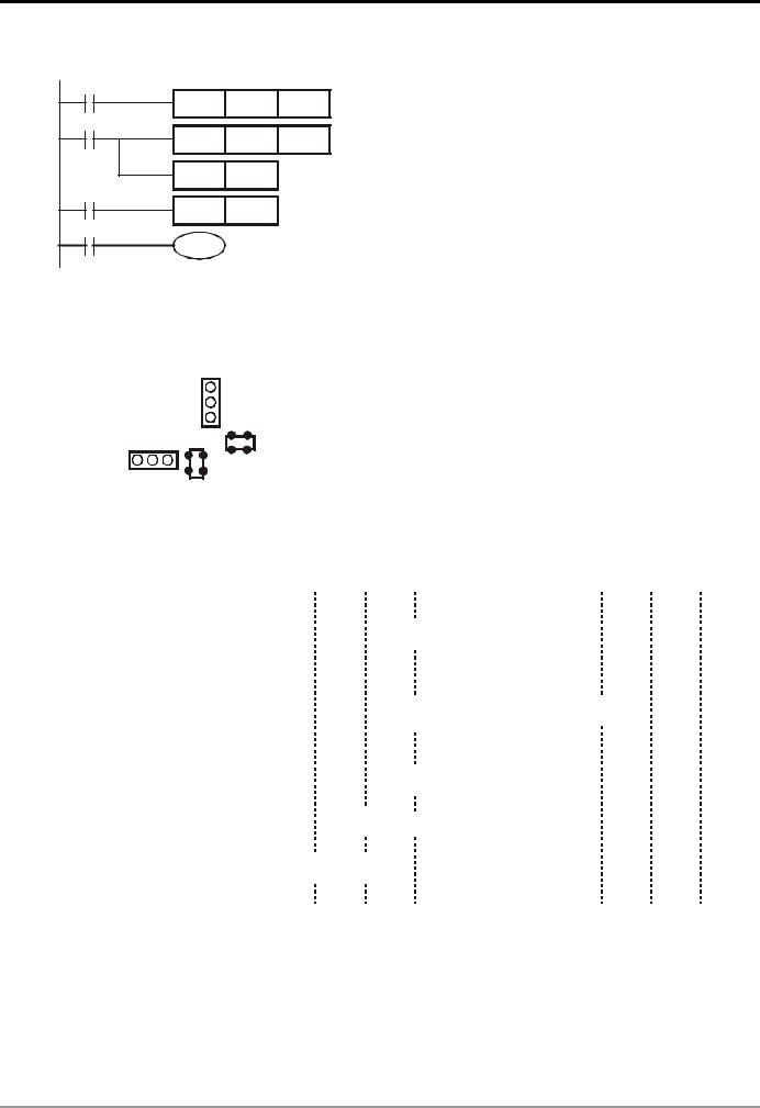
1 Basic Principles of PLC Ladder Diagram
Example 14: How to enlarge the counting range
X13
CNT C5 Kn1
C5
CNT C6 Kn2
RST C5
X14
RST C6
C6
Y1
The counting range of a 16-bit counter is 0 ~ 32,767. As the circuit in the left hand side, using two counters can increase the counting range to n1*n2. When the counting of counter C5 reaches n1, C6 will start to count for one time and reset for counting the pulses from X13. When the counting of counter C6 reaches n2, the pulses from input X13 will be n1*n2.
Example 15: Traffic light control (by using step ladder instruction)
|
|
|
|
|
|
|
|
|
|
|
|
|
|
|
|
|
|
|
|
|
|
|
|
Traffic light control |
|
|
|
|
|
|
|
|
|
|
||
|
|
|
|
|
|
|
|
|
|
|
|
|
|
|
|
|
|
|
|
|
|
|
|
|
|
|
|
|
|
|
|
|
|
|
|
|
|
|
|
|
|
|
|
|
|
|
Vertical |
|
|
|
Red light |
Yellow |
|
Green |
Green |
||||||||||||||||||
|
|
|
|
|
|
|
|
|
|
|
|
|
|
|||||||||||||||||||||||
|
|
|
|
|
|
|
|
|
|
|
|
|
|
|
light |
|||||||||||||||||||||
|
|
|
|
|
|
|
|
|
|
|
|
|
light |
|
|
light |
|
|||||||||||||||||||
|
|
|
|
|
|
|
|
|
|
Light |
|
|
|
|
|
|
flashes |
|||||||||||||||||||
|
|
|
|
|
|
|
|
|
|
|
|
|
|
|
|
|
|
|
|
|
||||||||||||||||
|
|
|
|
|
|
|
|
|
|
|
|
|
|
|
|
|
|
|
|
|
|
|
|
Vertical |
Y0 |
Y1 |
|
|
|
Y2 |
|
Y2 |
||||
|
|
|
|
|
|
|
|
|
|
|
|
|
|
|
|
|
|
|
|
|
|
|
|
|
|
|
||||||||||
|
|
|
|
|
|
|
|
|
|
|
|
|
|
|
|
|
|
|
|
|
|
|
|
light |
|
|
|
|
||||||||
|
|
|
|
|
|
|
|
|
|
|
|
|
|
|
|
|
|
|
|
|
|
|
|
|
|
|
|
|
|
|
|
|
|
|
||
|
|
|
|
|
|
|
|
|
|
|
|
|
|
|
|
|
|
|
|
|
|
|
|
|
|
|
|
|
|
|
|
|
|
|||
|
|
|
|
|
|
|
|
|
|
|
|
|
|
|
|
|
|
|
|
|
|
|
|
|
|
|
|
|
|
|
|
|
|
|
|
|
|
|
|
|
|
|
|
|
|
|
|
|
|
|
|
|
|
|
|
|
|
|
|
|
Horizontal |
Y10 |
Y11 |
|
|
Y12 |
|
Y12 |
|||||
|
|
|
|
|
|
|
|
|
|
|
|
|
|
|
|
|
|
|
|
|
|
|
|
|
|
|||||||||||
|
Horizontal |
|
|
|
|
|
|
|
|
|
|
|
|
|
|
|
|
|
|
|
|
|
|
|||||||||||||
|
|
|
|
|
|
|
|
|
|
|
|
|
|
|
|
|
|
|
|
|
light |
|
|
|
||||||||||||
|
|
|
|
|
|
|
|
|
|
|
|
|
|
|
|
|
|
|
|
|
||||||||||||||||
|
|
|
|
|
|
|
|
|
|
|
|
|
|
|
|
|
|
|
|
|
|
|
|
|
|
|
|
|
|
|
|
|||||
|
Light |
|
|
|
|
|
|
|
|
|
|
|
|
|
|
|
|
|
|
|
|
|
|
|
|
|
|
|
|
|
|
|
|
|
||
|
|
|
|
|
|
|
|
|
|
|
|
|
|
|
|
|
|
|
|
|
On time |
35 secs |
5 secs |
|
25 secs |
5 secs |
||||||||||
|
|
|
|
|
|
|
|
|
|
|
|
|
|
|
|
|
|
|
|
|
|
|
|
|
||||||||||||
Timing Diagram: |
|
|
|
|
|
|
|
|
|
|
|
|
|
|
|
|
|
|
|
|
|
|
|
|
|
|
|
|
|
|
|
|
|
|||
|
|
|
|
|
|
|
|
|
|
|
|
|
|
|
|
|
|
|
|
|
|
|
|
|
|
|
|
|
|
|
|
|
||||
|
|
|
|
|
|
|
|
|
|
|
|
|
|
|
|
|
|
|
|
|
|
|
|
|
|
|
|
|
|
|
|
|
||||
Vertical |
|
|
|
|
|
|
|
|
|
|
|
|
|
|
|
|
|
|
|
|
|
|
|
|
|
|
|
|
|
|
|
|
|
|||
Light |
|
|
|
|
|
|
|
|
|
|
|
|
|
|
|
|
|
|
|
|
|
|
|
|
|
|
|
|
|
|
|
|
|
|||
|
|
|
|
|
|
|
|
|
|
|
|
|
|
|
|
|
|
|
|
|
|
|
|
|
|
|
|
|
|
|
|
|
|
|
||
Red Y0 |
|
|
|
|
|
|
|
|
|
|
|
|
|
|
|
|
|
|
|
|
|
|
|
|
|
|
|
|
|
|
|
|
|
|||
Yellow Y1 |
|
|
|
|
|
|
|
|
|
|
|
|
|
|
|
|
|
|
|
|
|
|
|
|
|
|
|
|
|
|
|
|
|
|||
|
|
|
|
|
|
|
|
|
|
|
|
|
|
|
|
|
|
|
|
|
|
|
|
|
|
|
|
|
|
|
|
|
||||
|
|
|
|
|
|
|
|
|
|
|
|
|
|
|
|
|
|
|
|
|
|
|
|
|
|
|
|
|
|
|
|
|
||||
|
|
|
|
|
|
|
|
|
|
|
|
|
|
|
|
|
|
|
|
|
|
|
|
|
|
|
|
|
|
|
|
|
|
|
||
|
|
|
|
|
|
|
|
|
|
|
|
|
|
|
|
|
|
|
|
|
|
|
|
|
|
|
|
|
|
|
|
|
|
|
|
|
Green Y2 |
|
|
|
|
|
|
|
|
|
|
|
|
|
|
|
|
|
|
|
|
|
|
25 secs |
|
|
|
|
|
|
|
|
|
|
|||
|
|
|
|
|
|
|
|
|
|
|
|
|
|
|
|
|
|
|
|
|
|
|
|
|
|
|
|
|
|
|
|
|
|
|
|
|
Horizontal |
|
|
|
|
|
|
|
|
|
|
|
|
|
|
|
|
|
|
|
|
|
|
|
|
5 secs 5 secs |
|||||||||||
|
|
|
|
|
|
|
|
|
|
|
|
|
|
|
|
|
|
|
|
|
|
|
|
|
|
|
|
|
|
|
|
|
||||
Light |
|
|
|
|
|
|
|
|
|
|
|
|
|
|
|
|
|
|
|
|
|
|
|
|
|
|
|
|
|
|
|
|
|
|||
Red Y10 |
|
|
|
|
|
|
|
|
|
|
|
|
|
|
|
|
|
|
|
|
|
|
|
|
|
|
|
|
|
|
|
|
|
|||
|
|
|
|
|
|
|
|
|
|
|
|
|
|
|
|
|
|
|
|
|
|
|
|
|
|
|
|
|
|
|
|
|
|
|
||
Yellow Y11 |
|
|
|
|
|
|
|
|
|
|
|
|
|
|
|
|
|
|
|
|
|
|
|
|
|
|
|
|
|
|
|
|
|
|||
|
|
|
|
|
|
|
|
|
|
|
|
|
|
|
|
|
|
|
|
|
|
|
|
|
|
|
|
|
|
|
|
|
||||
|
|
|
|
|
|
|
|
|
|
|
|
|
|
|
|
|
|
|
|
|
|
|
|
|
|
|
||||||||||
|
|
|
|
|
|
|
|
|
|
|
|
|
|
|
|
|
|
|
|
|
|
|
|
|
|
|
||||||||||
Green Y12 |
25 secs |
|
|
|
|
|
|
|
|
|
|
|
|
|
|
|
|
|
|
|
|
|
|
|
|
|||||||||||
|
|
|
|
|
|
|
|
|
|
|
|
|
|
5 secs |
5 secs |
|
|
|
|
|
|
|
|
|
|
|
||||||||||
DVP-PLC Application Manual |
1-21 |

1 Basic Principles of PLC Ladder Diagram
SFC Figure:
 M1002
M1002
S0
S20 |
|
|
|
|
|
Y0 |
|
|
S30 |
||||||
|
|
|
|
||||||||||||
T0 |
|
|
|
|
|
|
|
|
TMR |
T0 |
K350 |
T10 |
|
|
|
|
|
|
|
|
|
|
|
|
|
|
|||||
|
|
|
|
|
|
|
|
|
|||||||
|
|
|
|
|
|
|
|
Y2 |
|
|
|
|
|
||
S21 |
|
|
|
|
|
|
|
S31 |
|||||||
|
|
|
|
|
|||||||||||
T1 |
|
|
|
|
|
|
|
|
TMR |
T1 |
K250 |
T11 |
|
|
|
|
|
|
|
|
|
|
|
|
|
|
|||||
|
|
|
|
|
|
|
|
|
|||||||
|
|
|
|
|
|
|
|
|
|
|
|
|
|
||
S22 |
|
|
|
|
|
TMR |
T2 |
K50 |
S32 |
||||||
|
|
|
|||||||||||||
|
|
|
|
|
M1013 |
Y2 |
|
|
|
|
|
||||
T2 |
|
|
|
|
|
|
|
|
|
|
T12 |
|
|
|
|
|
|
|
|
|
|
|
|
|
|
|
|
|
|||
|
|
|
|
|
|
|
|
|
|
|
|
|
|
||
S23 |
|
|
|
|
|
|
Y1 |
|
S33 |
||||||
|
|
|
|
|
|
|
|||||||||
T13 
S0
|
|
|
Ladder Diagram: |
|
|
||
|
|
|
M1002 |
|
ZRST |
S0 |
S127 |
|
|
|
|
|
|||
|
|
|
|
|
SET |
S0 |
|
Y12 |
|
|
S0 |
|
SET |
S20 |
|
TMR |
T10 |
K250 |
S |
|
|
||
|
|
SET |
S30 |
|
|||
TMR |
T11 |
K50 |
|
|
|
||
S20 |
|
|
|
|
|||
M1013 |
|
|
|
Y0 |
|
|
|
Y12 |
|
S |
|
|
|
||
|
|
|
|
|
|
|
|
Y11 |
|
|
|
|
TMR |
T0 |
K350 |
TMR |
T12 |
K50 |
|
T0 |
SET |
S21 |
|
|
|
|
|||||
|
Y10 |
|
S21 |
|
|
|
|
|
|
S |
|
Y2 |
|
|
|
|
|
|
|
|
|
||
TMR |
T13 |
K350 |
|
|
TMR |
T1 |
K250 |
|
|
|
|
|
|||
|
|
|
|
T1 |
SET |
S22 |
|
|
|
|
|
|
|
||
|
|
|
S22 |
|
TMR |
T2 |
K50 |
|
|
|
S |
|
|||
|
|
|
|
M1013 |
|
|
|
|
|
|
|
|
Y2 |
|
|
|
|
|
|
T2 |
SET |
S23 |
|
|
|
|
|
|
|
||
|
|
|
S23 |
|
|
|
|
|
|
|
S |
|
Y1 |
|
|
|
|
|
S30 |
|
Y12 |
|
|
|
|
|
S |
|
|
|
|
|
|
|
|
|
TMR |
T10 |
K250 |
|
|
|
|
T10 |
SET |
S31 |
|
|
|
|
|
|
|
||
|
|
|
S31 |
|
TMR |
T11 |
K50 |
|
|
|
S |
|
|||
|
|
|
|
M1013 |
|
|
|
|
|
|
|
|
Y12 |
|
|
|
|
|
|
T11 |
SET |
S32 |
|
|
|
|
|
|
|
||
|
|
|
S32 |
|
Y11 |
|
|
|
|
|
S |
|
|
|
|
|
|
|
|
|
TMR |
T12 |
K50 |
|
|
|
|
T12 |
SET |
S33 |
|
|
|
|
|
|
|
||
|
|
|
S33 |
|
|
|
|
|
|
|
S |
|
Y10 |
|
|
|
|
|
|
|
TMR |
T13 |
K350 |
|
|
|
S23 |
S33 |
T13 |
|
|
|
|
|
S |
S |
S0 |
|
|
|
|
|
|
|
RET |
|
|
|
|
|
|
|
END |
|
|
1-22 |
DVP-PLC Application Manual |

1 Basic Principles of PLC Ladder Diagram
Drawing by SFC Editor (WPLSoft )
Drawn by SFC |
Internal Ladder Diagram |
|
|
|
|
|
LAD-0 |
|
|
|
|
M1002 |
|
|
|
|
ZRST |
S0 |
S127 |
LAD-0 |
|
SET |
S0 |
|
|
|
|
|
|
S0 |
|
|
|
|
|
|
Transferring Condition 1 |
|
|
0 |
|
|
|
|
|
|
T0 |
|
|
|
|
TRANS* |
|
|
S20 |
S30 |
|
|
|
1 |
5 |
S22 |
|
|
|
|
|
|
|
S21 |
S31 |
|
|
|
2 |
6 |
TMR |
T2 |
K50 |
M1013 |
|
|
||
S22 |
S32 |
|
|
|
Y2 |
|
|
||
3 |
7 |
|
|
|
S23 |
S33 |
Transferring Condition 4 |
|
|
|
|
|
||
|
|
T13 |
|
|
|
|
TRANS* |
|
|
4 |
|
|
|
|
S0 |
|
Transferring Condition 7 |
|
|
|
|
|
|
|
|
|
T12 |
|
|
|
|
TRANS* |
|
|
DVP-PLC Application Manual |
1-23 |

1 Basic Principles of PLC Ladder Diagram
MEMO
1-24 |
DVP-PLC Application Manual |

2 Functions of Devices in DVP-PLC
2.1All Devices in DVP-PLC
ES/EX/SS series MPU:
Type |
Device |
|
|
Item |
|
Range |
|
Function |
||
|
|
|
|
|
|
|
|
|
|
|
|
X |
External input relay |
|
X0 ~ X177, 128 points, octal |
Total |
Corresponds to external |
||||
|
|
input points |
||||||||
|
|
|
|
|
|
|
|
|||
|
Y |
External output relay |
|
Y0 ~ Y177, 128 points, octal |
256 points |
Corresponds to external |
||||
|
|
|
output points |
|||||||
|
|
|
|
|
|
|
|
|
||
|
|
|
General purpose |
M0 ~ M511, M768 ~ M999, 744 |
|
|
||||
|
|
|
points |
|
|
|||||
|
|
Auxiliary |
|
|
|
Total |
The contact can be |
|||
|
M |
Latched* |
|
M512 ~ M767, 256 points |
||||||
|
|
relay |
|
|
|
|
|
1,280 points |
On/Off in the program. |
|
|
|
|
Special purpose |
M1000 ~ M1279, 280 points |
|
|
||||
|
|
|
(some are latched) |
|
|
|||||
|
|
|
|
|
|
|
|
|||
|
|
|
100ms timer |
|
T0 ~ T63, 64 points |
|
Timer indicated by TMR |
|||
|
|
|
|
|
|
|
|
|
||
|
|
|
|
|
|
|
|
|
||
|
|
|
|
|
|
T64 ~ T126, 63 points (M1028 |
Total |
instruction. If timing |
||
(bit) |
T |
Timer |
10ms timer (M1028 = On) |
reaches its target, the T |
||||||
= Off: 100ms) |
128 points |
|||||||||
|
|
|
|
|
contact of the same No. |
|||||
Relay |
|
|
|
|
|
|
|
|
will be On. |
|
|
|
1ms timer |
|
T127, 1 points |
|
|||||
|
|
|
|
|
||||||
|
|
|
|
|
|
|||||
|
|
|
|
|
|
|
|
|
|
|
|
|
|
16-bit counting up |
C0 ~ C111, 112 points |
Total |
|
||||
|
|
|
(general purpose) |
|
||||||
|
|
|
|
|
128 points |
Counter indicated by |
||||
|
|
|
16-bit counting up (latched*) |
C112 ~ C127, 16 points |
||||||
|
|
|
32-bit |
1-phase 1 input |
C235 ~ C238, C241, C242, |
|
CNT (DCNT) instruction. |
|||
|
C |
Counter |
counting |
C244, 7 points |
|
If counting reaches its |
||||
|
|
|
||||||||
|
|
|
up/down |
|
|
|
Total |
target, the C contact of |
||
|
|
|
1-phase 2 inputs |
C246, C247, C249, 3 points |
||||||
|
|
|
high-speed |
|
|
|
13 points |
the same No. will be On. |
||
|
|
|
counter |
2-phase 2 inputs |
C251, C252, C254, 3 points |
|
|
|||
|
|
|
(latched*) |
|
|
|
|
|
||
|
|
|
Initial step (latched*) |
S0 ~ S9, 10 points |
Total |
|
||||
|
S |
Step |
Zero return (latched*) |
S10 ~ S19, 10 points (used with |
Used for SFC. |
|||||
|
IST instruction) |
128 points |
||||||||
|
|
|
|
|
|
|
||||
|
|
|
Latched* |
|
S20 ~ S127, 108 points |
|
|
|||
|
|
|
|
|
|
|
|
|
When the timing |
|
|
T |
Present value of timer |
|
T0 ~ T127, 128 points |
|
reaches the target, the |
||||
data) |
|
|
contact of the timer will |
|||||||
|
|
|
|
|
|
|
|
|||
|
|
|
|
|
|
|
|
be On. |
||
|
|
|
|
|
|
|
|
|
||
(word |
|
|
|
|
|
C0 ~ C127, 16-bit counter, 128 points |
When the counting |
|||
C |
Present value of counter |
reaches the target, the |
||||||||
C235 ~ C254, 32-bit counter, 13 points |
contact of the counter |
|||||||||
Register |
|
|
|
|
|
|
|
|
will be On. |
|
|
Data |
|
General purpose |
D0 ~ D407, 408 points |
|
600 points |
storage; E, F can be |
|||
|
|
|
|
|
Total |
Memory area for data |
||||
|
D |
register |
|
Latched* |
|
D408 ~ D599, 192 points |
|
|
used for index |
|
|
|
|
Special purpose |
D1000 ~ D1311, 312 points |
|
Total |
||||
|
|
|
|
|
indication. |
|||||
|
|
|
|
Index indication |
E, F, 2 points |
|
312 points |
|||
|
|
|
|
|
|
|||||
|
N |
For master control nested loop |
N0 ~ N7, 8 points |
|
Control point for main |
|||||
|
|
control loop |
||||||||
|
|
|
|
|
|
|
|
|
||
|
P |
For CJ, CALL instructions |
P0 ~ P63, 64 points |
|
Position index for CJ |
|||||
Pointer |
|
and CALL |
||||||||
|
|
|
|
|
|
|
|
|||
|
|
|
External interruption |
I001, I101, I201, I301, 4 points |
|
|
||||
|
|
|
|
|
|
|||||
|
|
|
|
|
|
|
|
Position index for |
||
|
I |
Interruption |
Timed interruption |
I6□□, 1 point (□□ 10 ~ 99, |
time base = |
|||||
|
1ms ) (for V5.7 and above) |
|
interruption subroutine. |
|||||||
|
|
|
|
|
|
|
||||
|
|
|
|
|
|
|
|
|||
|
|
|
|
Communication interruption |
I150, 1 point |
|
|
|||
Constant |
K |
Decimal form |
|
K-32,768 ~ K32,767 (16-bit operation) |
|
|||||
|
H0000 ~ HFFFF (16-bit operation) |
|
||||||||
H |
Hexadecimal form |
|
|
|||||||
|
|
|
|
|
|
K-2,147,483,648 ~ K2,147,483,647 (32-bit operation) |
||||
|
|
|
|
|
|
H00000000 ~ HFFFFFFFF (32-bit operation) |
|
|||
|
|
|
|
|
|
|
|
|
|
|
* The latched area is fixed and cannot be changed.
DVP-PLC Application Manual |
2-1 |

2 Functions of Devices in DVP-PLC
SA/SX/SC series MPU:
Type |
Device |
|
|
Item |
Range |
|
Function |
|
|
|
|
|
|
|
|
|
|
|
X |
External input relay |
X0 ~ X177, 128 points, octal |
|
Total |
Corresponds to external |
||
|
|
input points |
||||||
|
|
|
|
|
|
|
256 |
|
|
|
|
|
|
|
|
Corresponds to external |
|
|
Y |
External output relay |
Y0 ~ Y177, 128 points, octal |
|
points |
|||
|
|
output points |
||||||
|
|
|
|
|
|
|
|
|
|
|
|
|
General purpose |
M0 ~ M511, 512 points (*1) |
|
Total |
|
|
M |
Auxiliary |
|
Latched* |
M512 ~ M999, 488 points (*3) |
|
The contact can be |
|
|
|
|
4,096 |
|||||
|
Relay |
|
|
M2000 ~ M4095, 2,096 points (*3) |
|
On/Off in the program. |
||
|
|
|
Special purpose |
M1000 ~ M1999, 1,000 points |
|
points |
||
|
|
|
|
|
|
|||
|
|
|
|
(some are latched) |
|
|
|
|
|
|
|
|
|
|
|
|
|
|
|
|
|
|
T0 ~ T199, 200 points (*1) |
|
|
|
|
|
|
|
100ms |
T192 ~ T199 for subroutine |
|
|
|
|
|
|
|
T250 ~ T255, 6 accumulative points |
|
|
Timer indicated by TMR |
|
|
|
|
|
|
|
|
||
|
|
|
|
|
(*4) |
|
|
|
|
|
|
|
|
|
Total |
instruction. If timing |
|
|
T |
Timer |
|
|
T200 ~ T239, 40 points (*1) |
|
256 |
reaches its target, the T |
|
|
|
|
10ms |
T240 ~ T245, 6 accumulative points |
|
points |
contact of the same No. |
|
|
|
|
|
(*4) |
|
|
will be On. |
|
|
|
|
|
|
|
|
|
|
|
|
|
1ms |
T246 ~ T249, 4 accumulative points |
|
|
|
|
|
|
|
(*4) |
|
|
|
|
(bit) |
|
|
|
|
|
|
|
|
|
|
|
16-bit counting up |
C0 ~ C95, 96 points (*1) |
|
Total |
|
|
Relay |
|
|
|
|
C96 ~ C199, 104 points (*3) |
|
235 |
|
|
|
|
32-bit counting up/down |
C216 ~ C234, 19 points (*3) |
|
|
||
|
|
|
|
points |
|
|||
|
|
|
|
|
C200 ~ C215, 16 points (*1) |
|
|
|
|
|
|
|
|
C235 ~ C244, 1-phase 1 input, 9 |
|
|
|
|
|
|
|
|
points (*3) |
|
Total |
Counter indicated by |
|
|
|
|
For SA/SX, 32-bit |
C246 ~ C249, 1-phase 2 inputs, 3 |
|
||
|
|
|
|
|
16 |
CNT (DCNT) instruction. |
||
|
C |
Counter |
|
high-speed counter |
points (*3) |
|
||
|
|
|
points |
If counting reaches its |
||||
|
|
|
C251 ~ C254, 2-phase 2 inputs, 4 |
|
||||
|
|
|
|
|
|
|
target, the C contact of |
|
|
|
|
|
|
points (*3) |
|
|
|
|
|
|
|
|
|
|
the same No. will be On. |
|
|
|
|
|
|
C235 ~ C245, 1-phase 1 input, 11 |
|
|
|
|
|
|
|
|
|
|
|
|
|
|
|
|
|
points (*3) |
|
Total |
|
|
|
|
|
For SC, 32-bit high-speed |
C246 ~ C250, 1-phase 2 inputs, 4 |
|
|
|
|
|
|
|
|
19 |
|
||
|
|
|
|
counter |
points (*3) |
|
|
|
|
|
|
|
|
points |
|
||
|
|
|
|
|
C251 ~ C255, 2-phase 2 inputs, 4 |
|
|
|
|
|
|
|
|
|
|
|
|
|
|
|
|
|
points (*3) |
|
|
|
|
|
|
|
Initial step |
S0 ~ S9, 10 points (*1) |
|
|
|
|
|
|
|
Zero return |
S10 ~ S19, 10 points (used with IST |
|
Total |
|
|
|
|
|
instruction) (*1) |
|
|
||
|
|
|
|
|
|
|
||
|
S |
Step point |
|
|
|
|
1,024 |
Used for SFC. |
|
|
General purpose |
S20 ~ S511, 492 points (*1) |
|
||||
|
|
|
|
|
|
|
points |
|
|
|
|
|
Latched* |
S512 ~ S895, 384 points (*3) |
|
|
|
|
|
|
|
|
|
|
||
|
|
|
|
Alarm |
S896 ~ S1023, 128 points (*3) |
|
|
|
|
|
|
|
|
|
|
|
|
|
|
|
|
|
|
|
|
When the timing |
|
T |
Present value of timer |
T0 ~ T255, 256 points |
|
reaches the target, the |
|||
|
|
contact of the timer will |
||||||
|
|
|
|
|
|
|
|
|
data) |
|
|
|
|
|
|
|
be On. |
C |
Present value of counter |
C0 ~ C199, 16-bit counter, 200 points |
|
When the counting |
||||
(word |
C200 ~ C254, 32-bit counter, 50 points (SC: 53 |
reaches the target, the |
||||||
|
|
|
|
points) |
|
will be On. |
||
|
|
|
|
|
|
|
|
contact of the counter |
Register |
|
|
|
General purpose |
D0 ~ D199, 200 points (*1) |
|
Total |
Memory area for data |
|
|
|
|
|
|
|||
|
|
|
|
|
D200 ~ D999, 800 points (*3) |
|
||
|
D |
Data |
|
Latched* |
|
storage; E, F can be |
||
|
|
|
5,000 |
|||||
|
register |
|
|
D2000 ~ D4999, 3,000 points (*3) |
|
used for index |
||
|
|
|
|
Special purpose |
D1000 ~ D1999, 1,000 points |
|
points |
indication. |
|
|
|
|
Index indication |
E0 ~ E3, F0 ~ F3, 8 points (*1) |
|
|
|
|
N/A |
File register |
|
K0 ~ K1,599 (1,600 points) (*4) |
|
Expanded register for |
||
|
|
|
data storage. |
|||||
|
|
|
|
|
|
|
|
|
2-2 |
DVP-PLC Application Manual |
 Loading...