


 Loading...

 VFD-F Series
Preface
Thank you for choosing DELTA’s high-performance VFD-F Series. VFD-F Series are manufactured by adopting high-quality components, material and incorporating the latest microprocessor technology available.
Getting Started
This manual will be helpful in the installation, parameter setting, troubleshooting, and daily maintenance of the AC motor drives. To guarantee safe operation of the equipment, read the following safety guidelines before connecting power to the AC drives. Keep this operating manual handy and distribute to all users for reference.
|
! |
WARNING |
|
|
|
||
|
|
|
|
! |
Always read this manual thoroughly before using VFD-F series AC Motor Drives. |
||
! |
DANGER! AC input power must be disconnected before any maintenance. Do not connect |
||
|
or disconnect wires and connectors while power is applied to the circuit. Maintenance must |
||
|
be performed by qualified technicians. |
|
|
! |
CAUTION! There are highly sensitive MOS components on the printed circuit boards. |
||
|
These components are especially sensitive to static electricity. To avoid damage to these |
||
|
components, do not touch these components or the circuit boards with metal objects or |
||
|
your bare hands. |
|
|
! |
DANGER! A charge may still remain in the DC-link capacitor with hazardous voltages even |
||
|
if the power has been turned off. To avoid personal injury, do not remove the cover of the |
||
|
AC drive until all “DISPLAY LED” lights on the digital keypad are off. Please note that there |
||
|
are live components exposed within the AC drive. Do not touch these live parts. |
||
! |
CAUTION! Ground the VFD-F using the ground terminal. The grounding method must |
||
|
comply with the laws of the country where the AC drive is to be installed. Refer to Basic |
||
|
Wiring Diagram. |
|
|
! |
DANGER! The AC drive may be destroyed beyond repair if incorrect cables are connected |
||
|
to the input/output terminals. Never connect the AC drive output terminals U/T1, V/T2, and |
||
|
W/T3 directly to the AC main circuit power supply. |
||
! |
CAUTION! The final enclosures of the AC drive must comply with EN50178. (Live parts |
||
|
shall be arranged in enclosures or located behind barriers that meet at least the |
||
|
requirements of the Protective Type IP20. The top surface of the enclosures or barrier that |
||
|
is easily accessible shall meet at least the requirements of the Protective Type IP40). |
||
|
(VFD-F series corresponds with this regulation.) |
||
! |
CAUTION! The rated voltage for the AC motor drive must be ≤ 240V for 230V models (≤ |
||
|
480V for 460V models) and the mains supply current capacity must be ≤ 5000A RMS |
||
|
(≤10000A RMS for the ≥ 40hp (30kW) models) |
||
CAUTION! Heat sink may heat up over 70oC (158oF), during the operation. Do not touch the heat sink.
DELTA ELECTRONICS, INC. ALL RIGHTS RESERVED

 VFD-F Series
TABLE OF CONTENTS
CHAPTER 1 RECEIVING AND INSPECTIONS |
|
|
|
1.1 |
Nameplate Information ........................................................................ |
1 |
- 1 |
1.2 |
Model Explanation ............................................................................... |
1 |
- 1 |
1.3 |
Serial Number Explanation.................................................................. |
1 |
- 2 |
CHAPTER 2 STORAGE AND INSTALLATION |
|
|
|
2.1 |
Storage................................................................................................. |
2 |
- 1 |
2.2 |
Installation............................................................................................ |
2 |
- 2 |
CHAPTER 3 WIRING |
|
|
|
3.1 |
Basic Wiring Diagram .......................................................................... |
3 |
- 2 |
3.2 Terminal Explanation ........................................................................... |
3 |
- 5 |
|
3.3 |
Control Terminal Explanation............................................................... |
3 |
- 5 |
3.4 |
Main Circuit Wiring ............................................................................. |
3 |
- 7 |
3.5 |
Wiring Notes ........................................................................................ |
3-16 |
|
3.6 |
Motor Operation Precautions .............................................................. |
3-18 |
|
CHAPTER 4 DIGITAL KEYPAD OPERATION |
|
|
|
4.1 |
VFD-PU01 ........................................................................................... |
4 - 1 |
|
4.2 |
KPF-CC01 ........................................................................................... |
4 - 5 |
|
CHAPTER 5 DESCRIPTION OF PARAMETER SETTINGS |
|
|
|
5.1 |
Group 0: AC Drive Status Parameters................................................. |
5 |
- 1 |
5.2 |
Group 1: Basic Parameters ................................................................. |
5 |
- 4 |
DELTA ELECTRONICS, INC. ALL RIGHTS RESERVED

 VFD-F Series
5.3 |
Group 2: Operation Method Parameters............................................. |
5 |
- 9 |
|
5.4 |
Group 3: Output Function Parameters ................................................ |
5-15 |
||
5.5 |
Group 4: Input Function Parameters................................................... |
5-19 |
||
5.6 |
Group 5: Multi-step Speed Frequency Parameters............................. |
5-24 |
||
5.7 |
Group 6: Protection Parameters.......................................................... |
5-30 |
||
5.8 |
Group 7: AC Drive and Motor Parameters .......................................... |
5-36 |
||
5.9 |
Group 8: Special Parameters .............................................................. |
5-39 |
||
5.10 Group 9: Communication Parameters............................................... |
5-45 |
|||
5.11 Group 10: PID Control Parameters ................................................... |
5-60 |
|||
5.12 Group 11: Fan and Pump Control Parameters.................................. |
5-63 |
|||
CHAPTER 6 MAINTENANCE AND INSPECTIONS |
|
|
||
6.1 |
Periodic Inspection .............................................................................. |
6 |
- 1 |
|
6.2 |
Periodic Maintenance .......................................................................... |
6 |
- 1 |
|
CHAPTER 7 TROUBLESHOOTING AND FAULT INFORMATION........... |
7 |
- 1 |
||
CHAPTER 8 SUMMARY OF PARAMETER SETTINGS ............................ |
8 |
- 1 |
||
APPENDIX A |
SPECIFICATIONS ................................................................ |
A - 1 |
||
APPENDIX B |
ACCESSORIES |
|
|
|
B.1 All Braking Resistors & Braking Units Use in AC Drives..................... |
B - 1 |
|||
B.2 AC Input Reactor Recommended Value ............................................. |
B - 3 |
|||
B.3 AC Output Reactor Recommended Value .......................................... |
B - 4 |
|||
DELTA ELECTRONICS, INC. ALL RIGHTS RESERVED

 VFD-F Series
B.4 |
Non-fuse Circuit Breaker Chart........................................................... |
B - 5 |
B.5 |
Fuse Specification Chart ..................................................................... |
B - 6 |
B.6 |
PU06.................................................................................................... |
B - 7 |
B.6.1 Description of the Digital Keypad VFD-PU06............................... |
B - 7 |
|
B.6.2 Explanation of Display Message .................................................. |
B - 7 |
|
B.6.3 PU06 Operation Flow Chart ......................................................... |
B - 8 |
|
B.7 Relay Card....................................................................................... |
B - 9 |
|
APPENDIX C DIMENSIONS........................................................................ |
C - 1 |
|
DELTA ELECTRONICS, INC. ALL RIGHTS RESERVED
 VFD-F Series
CHAPTER 1 RECEIVING AND INSPECTION
1
This VFD-F AC drive has gone through rigorous quality control tests at the factory before shipment. After receiving the AC drive, please check for the following:
Receiving
9Check to make sure that the package includes an AC drive, the User Manual, dust covers and rubber bushings.
9Inspect the unit to insure it was not damaged during shipment.
9Make sure that the part number indicated on the nameplate corresponds with the part number of your order.
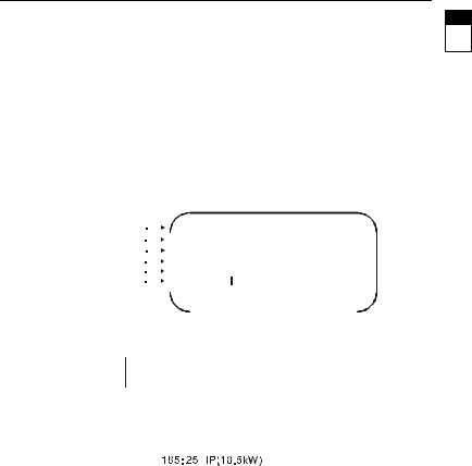
1.1 Nameplate Information: Example for 7.5HP/5.5kW 3-phase 460V AC drive
AC Drive Model |
|
MODEL |
|
: VFD055F43A |
|
|
||||||||||||||||||
Input Spec. |
|
INPUT |
|
: 3PH 380-480V 50/60Hz 14A |
||||||||||||||||||||
Output Spec. |
|
OUTPUT : 3PH 0-480V 13A 9.9KVA 7.5HP |
||||||||||||||||||||||
Output Frequency Range |
|
Frequency Range : 1.5-120Hz |
|
|
||||||||||||||||||||
Enclosure type |
|
Enclosure: TYPE 1 |
|
|
||||||||||||||||||||
Serial Number & Bar Code |
|
|
|
|
|
|
|
|
|
|
|
|
|
|
|
|
|
|
|
|
|
|
|
|
|
|
|
|
|
|
|
|
055F43AT201001 |
|
|
||||||||||||||
|
|
|
|
|
|
|
|
|
|
|||||||||||||||
|
|
DELTA ELECTRONICS INC. |
MADE IN XXXXX |
|||||||||||||||||||||
|
|
|
|
|
|
|
|
|
|
|
|
|
|
|
|
|
|
|
|
|
|
|
|
|
1.2 Model Explanation
VFD 055 F 43 A |
|
|
|
|||||
|
|
|
|
|
|
|
Version Type |
|
|
|
|
|
|
|
|
|
|
|
|
|
|
|
|
|
Input Voltage |
|
|
|
|
|
|
|
|
|
|
|
|
|
|
|
|
|
23:Three phase 230V |
|
|
|
|
|
|
|
|
43:Three phase 460V |
|
Series |
|
|
|
|
|
VFD-F Series |
|
|
|
|
|
||||||
Name |
|
|
Applicable motor capacity |
|||||
007: 1.0HP(0.75kW) |
|
|||||||
150: 20HP(15kW) |
750: 100HP(75kW) |
|||||||
015: 2.0HP(1.5kW) |
|
|
900: 120HP(90kW) |
|||||
022: 3.0HP(2.2kW) |
|
220: 30 HP(22kW) |
1100: 150HP(110kW) |
|||||
037: 5.0HP(3.7kW) |
300: 40HP(30kW) |
1320: 175HP(130kW) |
||||||
055: 7.5HP(5.5kW) |
370: 50HP(37kW) |
1600: 215HP(160kW) |
||||||
075: 10 HP(7.5kW) |
|
450: 60HP(45kW) |
1850: 250HP(185kW) |
|||||
110: 15 HP(11kW) |
550: 75HP(55kW) |
2200: 300HP(220kW) |
||||||
DELTA ELECTRONICS, INC. ALL RIGHTS RESERVED |
1-1 |
 VFD-F Series
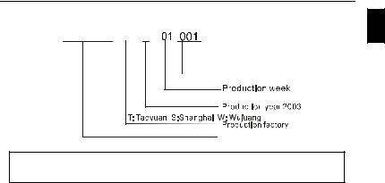
1.3 Series Number Explanation
1
055F43A  3
3
 Production number
460V 3-PHASE 7.5HP(5.5kW) |
Production model |
|
If there is any nameplate information not corresponding to your purchase order or any problem, please contact your distributor.
1-2 |
DELTA ELECTRONICS, INC. ALL RIGHTS RESERVED |

 VFD-F Series
CHAPTER 2 STORAGE AND INSTALLATION |
|
|
2.1 Storage |
|
|
2 |
||
The AC drive should be kept in the shipping carton before installation. In order to retain the |
||
|
||
warranty coverage, the AC drive should be stored properly when it is not to be used for an |
|
|
|
||
extended period of time. |
|
Ambient Conditions: |
|
||
Operation |
Air Temperature: -10oC to +40oC (14oF to 104oF) |
||
+50oC (122oF) without dust cover. |
|||
|
|||
|
Atmosphere pressure: 86 to 106 kPa |
||
|
Installation Site Altitude: below 1000m |
||
|
Vibration: Maximum 9.80 m/s2 |
(1G) at less than 20Hz |
|
|
Maximum 5.88 m/s2 |
(0.6G) at 20Hz to 50Hz |
|
Storage
Transportation
Temperature: -20oC to +60oC (-4oF to 140oF)
Relative Humidity: Less than 90%, no condensation allowed Atmosphere pressure: 86 to 106 kPa
Temperature: -20oC to +60oC (-4oF to 140oF)
Relative Humidity: Less than 90%, no condensation allowed Atmosphere pressure: 86 to 106 kPa
Vibration: Maximum 9.86 m/s2 (1G) at less than 20Hz, Maximum 5.88 m/s2 (0.6G) at 20Hz to 50Hz
Pollution Degree |
2: good for a factory type environment. |
DELTA ELECTRONICS, INC. ALL RIGHTS RESERVED |
2-1 |
 VFD-F Series
2.2 Installation
CAUTION
The control, power supply and motor leads must be laid separately. They must not be fed through the same cable conduit / trunking.
High voltage insulation test equipment must not be used on cables connected to the drive.
Improper installation of the AC drive will greatly reduce its life. Be sure to observe the following precautions when selecting a mounting location.
Failure to observe these precautions may void the warranty!
Do not mount the AC drive near heat-radiating elements or in direct sunlight.
Do not install the AC drive in a place subjected to high temperature, high humidity, excessive vibration, corrosive gases or liquids, or airborne dust or metallic particles.
Mount the AC drive vertically and do not restrict the air flow to the heat sink fins.
The AC drive generates heat. Allow sufficient space around the unit for heat dissipation.
150mm |
|
|
50m |
VFD-F |
|
|
|
|
m |
|
RUN |
|
|
|
|
|
50m m |
|
|
150mm |
Air Flow |
2-2 |
DELTA ELECTRONICS, INC. ALL RIGHTS RESERVED |

 VFD-F Series
CHAPTER 3 WIRING
DANGER
Hazardous Voltage
Before accessing the AC drive:
Disconnect all power to the AC drive. 3Wait five minutes for DC bus capacitors discharge.
Any electrical or mechanical modification to this equipment without prior written consent of Delta Electronics, Inc. will void all warranties and may result in a safety hazard in addition to voiding the UL listing.
Short Circuit Withstand:
The rated voltage for the AC motor drive must be ≤ 240V for 230V models (≤ 480V for 460V models) and the mains supply current capacity must be ≤ 5000A RMS (≤10000A RMS for the ≥ 40hp (30kW) models)
DELTA ELECTRONICS, INC. ALL RIGHTS RESERVED |
3-1 |
VFD-F Series
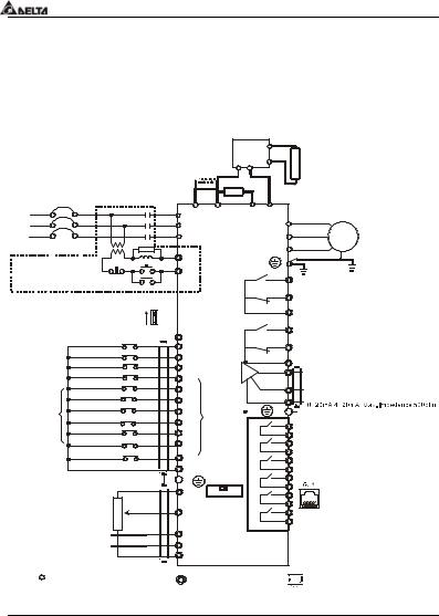
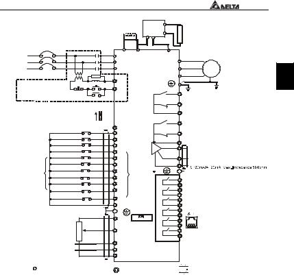
3.1 Basic Wiring Diagram
Users must connect wires according to the following circuit diagram shown below. Do not plug a Modem or telephone line to the RS-485 communication port, permanent damage may result. Pins 1 & 2 are the power sources for the optional copy keypad and should not be used while using RS-485 communication.
For 230V series, 1-15 hp models |
|
|
|
|
Brake |
|
|||||
460V series, 1-20hp models |
|
|
|
|
Unit (Optional) |
||||||
|
|
VFDB B1 |
|
||||||||
|
|
|
|
|
|
|
|
|
|||
|
|
|
|
|
|
DC Reactor |
P N B2 |
Brake |
|||
|
|
|
|
|
|
(Optional) |
|
|
|
||
|
|
|
|
|
|
|
|
|
|
|
Resistor |
|
|
|
|
|
|
Jumper |
BR |
|
|
(Optional) |
|
|
|
|
|
|
|
|
|
|
|||
|
|
NFB |
|
|
|
|
|
|
|
||
|
|
|
|
|
|
|
|
|
|
||
R/L1 |
|
|
|
|
|
+1 |
+2/B1 |
|
B2 |
- |
Motor |
|
|
|
|
|
R/L1 |
|
|||||
S/L2 |
|
|
|
|
|
S/L2 |
VFD-F |
U/T1 |
IM |
||
T/L3 |
NFB |
|
|
T/L3 |
V/T2 |
||||||
|
|
SA |
|
|
|
W/T3 |
3~ |
||||
|
|
|
|
|
RB1 |
|
|
|
|||
Recommended Circuit |
ON |
|
|
|
|
|
|
||||
when power supply |
|
RC1 |
|
|
|
|
|
||||
|
|
|
|
|
RA1 |
|
|||||
is turned OFF by a |
OFF |
|
MC |
|
|
|
Multi-function indication |
||||
fault output |
|
|
|
|
|
|
|
|
RB1 |
output contacts |
|
|
Factory Setting: SINK Mode |
|
|
|
|
|
|
||||
|
Sink |
|
|
|
RC1 |
|
|||||
|
Please refer to following |
|
|
|
|
||||||
|
|
Sw1 |
|
|
|
|
|
||||
|
wiring for SINK mode and Source |
|
|
|
RA2 |
Please refer to |
|||||
|
SOURCE mode. |
|
|
+24V |
|
|
|
RB2 |
Terminal Explanation |
||
|
|
|
FWD/STOP |
|
|
|
|
|
|||
|
|
|
|
FWD |
|
|
|
|
|||
|
|
|
REV/STOP |
|
|
|
|
|
|
||
|
|
|
|
REV |
|
|
|
RC2 |
|
||
|
|
|
E.F. |
|
|
|
|
|
|
||
|
|
|
|
|
EF |
|
|
|
|
Multi-function Analog |
|
|
|
|
Multi-step1 |
|
|
|
|
AFM1 |
|||
|
|
|
|
MI1 |
|
|
|
output terminal |
|||
|
|
|
Multi-step2 |
|
|
|
|
||||
|
|
|
|
MI2 |
|
|
|
AFM2 |
Factory setting: output frequency |
||
|
|
|
Multi-step3 |
|
Multi- |
|
|
ACM |
0~10VDC/2mA |
||
|
|
|
Multi-step4 |
|
MI3 |
|
|
Factory setting: output current |
|||
|
|
|
|
function |
|
E |
Analog Signal Common |
||||
|
|
|
RESET |
|
|
MI4 |
input |
|
|
||
|
Factory |
|
|
MI5 |
terminals |
RY00 RA3 |
|
||||
|
JOG |
|
|
MI6 |
|
|
|
RC3 |
|
||
|
setting |
|
|
|
|
|
|
|
|||
|
|
Accel/Decel prohibit |
|
|
|
|
RA4 |
|
|||
|
|
|
|
MI7 |
|
|
|
|
|||
|
|
|
1/2 Accel/Decel switch |
|
|
|
|
RC4 |
|
||
|
|
|
|
|
|
|
|
|
|||
|
|
|
|
MI8 |
|
|
|
RA5 |
|
||
|
|
|
Digital Signal Common |
|
|
|
|
||||
|
|
|
DCM |
|
|
|
RC5 |
|
|||
|
*Don't apply the mains voltage |
|
|
|
RA6 |
|
|||||
|
E |
|
|
|
|
||||||
|
directly to above terminals. |
|
|
|
RC6 |
|
|||||
|
+10V 0-5V Sw20-10V |
|
RA7 |
|
|||||||
|
|
|
|
|
|
|
RS-485 |
||||
|
|
|
5Kohm |
3 |
|
Power supply |
|
|
RC7 |
Serial communication interface |
|
|
|
|
|
2 |
|
+10V 20mA |
|
|
RA8 |
|
|
|
|
|
|
|
AVI |
|
|
|
RC8 |
1: +EV 2: GND 3: SG- |
|
|
|
|
|
|
|
Master Frequency |
|
||||
|
|
|
|
1 4~20mA |
0~10V/5V(47Kohm) |
Relay B.D. |
4: SG+ 5:NC |
||||
|
|
|
|
4~20mA |
ACI1 (250ohm) |
|
(Optional) |
6: for communication |
|||
|
|
|
|
ACI2(250ohm) |
|
|
|
|
|||
|
|
|
|
|
|
ACM |
|
|
|
|
|
|
|
|
Analog Signal Common |
|
|
|
|
|
|||
|
Main circuit (power) terminals |
Control circuit terminals |
Shielded leads & Cable |
||||||||
|
|
|
|
|
|
|
3-2 |
|
|
DELTA ELECTRONICS, INC. ALL RIGHTS RESERVED |
|
|
|
|
|
|
|
|
|
|
|
|
VFD-F Series |
|
For 230V series, 20hp and above models |
|
|
|
Brake |
|
|
||||||
460V series, 25hp and above models |
|
|
|
Unit (Optional) |
|
|||||||
DC Reactor VFDB B1 |
|
|
||||||||||
|
|
|
|
|
|
|
(Optional) |
P N B2 |
Brake |
|
||
|
|
|
|
|
|
|
|
|
|
|||
|
|
|
|
|
|
|
|
|
|
|
Resistor |
|
|
|
|
|
|
|
Jumper |
|
|
|
(Optional) |
|
|
|
|
NFB |
|
|
|
|
|
|
|
|||
|
|
|
|
|
+1 |
|
|
- |
|
|
||
R/L1 |
|
|
MC |
|
|
+2 |
|
Motor |
|
|||
|
|
|
|
|
R/L1 |
|
|
U/T1 |
|
|||
S/L2 |
|
|
|
|
|
|
S/L2 |
|
|
IM |
|
|
T/L3 |
NFB |
|
|
|
T/L3 |
VFD-F V/T2 |
|
|||||
|
SA |
|
|
|
|
W/T3 |
3~ |
3 |
||||
Recommended Circuit |
|
RB1 |
|
|
|
|||||||
ON |
|
|
|
|
|
|
|
|||||
when power supply |
|
|
RC1 |
|
|
|
|
|
||||
|
|
|
|
|
RA1 |
|
|
|||||
is turned OFF by a |
OFF |
|
MC |
|
|
|
Multi-function indication |
|
||||
fault output |
|
|
|
|
|
|
|
|
output contacts |
|
||
|
|
|
|
|
|
|
|
RB1 |
|
|||
|
Factory Setting: SINK Mode |
|
|
|
|
|
|
|
||||
|
Sink |
|
|
|
RC1 |
|
|
|||||
|
Please refer to following |
|
|
|
|
|
||||||
|
|
Sw1 |
|
|
|
|
Please refer to |
|
||||
|
wiring for SINK mode and |
|
|
|
|
RA2 |
|
|||||
|
Source |
|
|
|
|
|||||||
|
SOURCE mode. |
|
|
|
|
Terminal Explanation |
|
|||||
|
|
|
|
+24V |
|
|
|
|
||||
|
|
|
FWD/STOP |
|
|
|
|
RB2 |
|
|
||
|
|
|
|
|
FWD |
|
|
|
|
|||
|
|
|
REV/STOP |
|
|
|
|
|
|
|
||
|
|
|
|
|
REV |
|
|
RC2 |
|
|
||
|
|
|
E.F. |
|
|
|
|
|
|
|
||
|
|
|
|
|
|
EF |
|
|
|
Multi-function Analog |
|
|
|
|
|
Multi-step1 |
|
|
|
|
AFM1 |
|
|||
|
|
|
Multi-step2 |
|
|
MI1 |
|
|
output terminal |
|
||
|
|
|
|
|
MI2 |
|
|
AFM2 |
Factory setting: output frequency |
|
||
|
|
|
Multi-step3 |
|
|
Multi- |
|
ACM |
0~10VDC/2mA |
|
||
|
|
|
|
|
MI3 |
|
Factory setting: output current |
|
||||
|
|
|
Multi-step4 |
|
|
function |
E |
Analog Signal Common |
|
|||
|
|
|
RESET |
|
|
|
MI4 |
input |
|
|
||
|
Factory |
|
|
|
MI5 |
terminals |
RY00 RA3 |
|
|
|||
|
JOG |
|
|
|
MI6 |
|
|
RC3 |
|
|
||
|
setting |
|
|
|
|
|
|
|
|
|||
|
|
Accel/Decel prohibit |
|
|
|
|
RA4 |
|
|
|||
|
|
|
|
|
MI7 |
|
|
|
|
|||
|
|
|
1/2 Accel/Decel switch |
|
|
|
|
RC4 |
|
|
||
|
|
|
|
|
|
|
|
|
|
|||
|
|
|
|
|
MI8 |
|
|
RA5 |
|
|
||
|
|
|
Digital Signal Common |
|
|
|
|
|
||||
|
|
|
|
DCM |
|
|
RC5 |
|
|
|||
|
*Don't apply the mains voltage |
|
|
|
RA6 |
|
|
|||||
|
|
E |
|
|
|
|
||||||
|
directly to above terminals. |
|
|
0-5V 0-10V |
RC6 |
|
|
|||||
|
|
|
+10V |
RA7 |
RS-485 |
|
||||||
|
|
|
|
|
|
|
Sw2 |
|
|
|||
|
|
|
5Kohm |
|
|
|
|
|
|
RC7 |
|
|
|
|
|
3 |
|
|
Power supply |
|
Serial communication interface |
|
|||
|
|
|
|
2 |
|
|
+10V 20mA |
|
RA8 |
|
|
|
|
|
|
|
|
|
AVI |
|
|
RC8 |
1: +EV 2: GND 3: SG- |
|
|
|
|
|
|
|
|
|
Master Frequency |
|
||||
|
|
|
|
1 4~20mA |
|
0~10V/5V(47Kohm) |
Relay B.D. |
4: SG+ 5:NC |
|
|||
|
|
|
|
4~20mA |
|
ACI1 (250ohm) |
(Optional) |
6: for communication |
|
|||
|
|
|
|
|
ACI2 (250ohm) |
|
|
|
||||
|
|
|
|
|
|
|
ACM |
|
|
|
|
|
|
|
|
Analog Signal Common |
|
|
|
|
|
|
|||
|
Main circuit (power) terminals |
|
Control circuit terminals |
Shielded leads & Cable |
|
|||||||
DELTA ELECTRONICS, INC. ALL RIGHTS RESERVED |
3-3 |
VFD-F Series
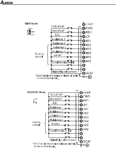
Wiring for SINK mode and SOURCE mode
JOG
1/2 Accel/Decel switch |
MI7 |
|
MI8 |
||
|
Sink


 Sw1
Sw1
Source
JOG
1/2 Accel/Decel switch |
MI7 |
|
MI8 |
||
|
3-4 |
DELTA ELECTRONICS, INC. ALL RIGHTS RESERVED |

 VFD-F Series
3.2 Terminal Explanations
Terminal Symbol |
|
Explanation of Terminal Function |
|
|
|||
R/L1, S/L2, T/L3 |
|
AC line input terminals |
|
|
|
||
U/T1, V/T2, W/T3 |
|
AC drive output terminals motor connections |
|
|
|||
+1,+2 |
|
|
Connections for DC Link Reactor (optional) |
|
|
||
|
|
|
3 |
||||
+2/B1~B2 |
|
Connections for Brake Resistor (optional) |
|
||||
+2~ -,+2/B1~ - |
|
Connections for External Brake Unit (VFDB series) |
|
|
|||
|
|||||||
|
|
|
Earth Ground |
|
|
|
|
|
|
|
|
|
|
|
|
3.3 Control Terminals Explanations |
|
|
|
||||
|
|
|
|
|
|
|
|
Terminal Symbols |
|
|
Terminal Functions |
|
Factory Settings |
|
|
FWD |
|
Forward-Stop command |
|
|
|
|
|
REV |
|
Reverse-Stop command |
|
|
|
|
|
EF |
|
External fault |
|
|
|
|
|
MI1 |
|
Multi-function Input 1 |
|
Factory default: Multi-step speed command 1 |
|
|
|
MI2 |
|
Multi-function Input 2 |
|
Factory default: Multi-step speed command 2 |
|
|
|
MI3 |
|
Multi-function Input 3 |
|
Factory default: Multi-step speed command 3 |
|
|
|
MI4 |
|
Multi-function Input 4 |
|
Factory default: Multi-step speed command 4 |
|
|
|
MI5 |
|
Multi-function Input 5 |
|
Factory default: RESET |
|
|
|
MI6 |
|
Multi-function Input 6 |
|
Factory default: JOG |
|
|
|
MI7 |
|
Multi-function Input 7 |
|
Factory default: Accel/Decel prohibit |
|
|
|
MI8 |
|
Multi-function Input 8 |
|
Factory default: Accel/Decel time switch 1 |
|
|
|
+24V |
|
DC Voltage Source |
|
(+24V, 20mA), used for source mode. |
|
|
|
DCM |
|
Digital Signal Common |
|
Used as common for digital inputs and used |
|
|
|
|
|
for sink mode. |
|
|
|||
|
|
|
|
|
|
|
|
DELTA ELECTRONICS, INC. ALL RIGHTS RESERVED |
3-5 |

VFD-F Series
Terminal Symbols |
Terminal Functions |
Factory Settings |
|
RA 1 |
Multi-function Relay1 output |
|
|
(N.O.) a |
|
||
|
|
||
RB 1 |
Multi-function Relay1 output |
|
|
(N.C.) b |
|
||
|
1.5A(N.O.)/1A(N.C.) 240VAC |
||
RC 1 |
Multi-function Relay1 common |
||
|
|
1.5A(N.O.)/1A(N.C.) 24VDC |
|
RA 2 |
Multi-function Relay2 output |
||
Refer to Pr.03-00 to Pr.03-01 |
|||
(N.O.) a |
|||
RB 2 |
Multi-function Relay2 output |
|
|
(N.C.) b |
|
||
|
|
||
RC 2 |
Multi-function Relay2 common |
|
|
+10V |
Potentiometer power source |
+10V 20mA |
|
|
|
|
|
AVI |
Analog voltage Input |
0 to +10V correspond to Max. |
|
operation frequency |
|||
|
|
||
ACI 1/2 |
Analog current Input |
4 to 20mA correspond to Max. |
|
operation frequency |
|||
|
|
||
AFM 1 |
Analog frequency /current |
0 to 10V correspond to Max. |
|
meter 1 |
operation frequency |
||
|
|||
AFM 2 |
Analog frequency /current |
4 to 20mA correspond to 2 times of |
|
meter 2 |
output current |
||
|
|||
|
|
||
ACM |
Analog control signal |
|
|
(common) |
|
||
|
|
* Control signal wiring size: 18 AWG (0.75 mm2).
3-6 |
DELTA ELECTRONICS, INC. ALL RIGHTS RESERVED |
 VFD-F Series
3.4 Main Circuit Wiring
1HP to 5HP
(VFD007F23A/43A, VFD015F23A/43A, VFD022F23A/43A, VFD037F23A/43A)
3

 +1
+1  +2
+2 B1
B1 -
-  B2
B2 

 R/L1
R/L1 S/L2
S/L2 T/L3
T/L3 


Control Terminal
Torque: 4Kgf-cm (3 in-lbf)
Wire: 12-24 AWG
Power Terminal
Torque: 18 kgf-cm (15.6 in-lbf) Wire Gauge: 10-18 AWG
Wire Type: Stranded copper only, 75° C
 U/T1
U/T1  V/T2
V/T2  W/T3
W/T3
Screw Torque :
18Kgf-cm
Wire Gauge :
18~10AWG
DELTA ELECTRONICS, INC. ALL RIGHTS RESERVED |
3-7 |
VFD-F Series
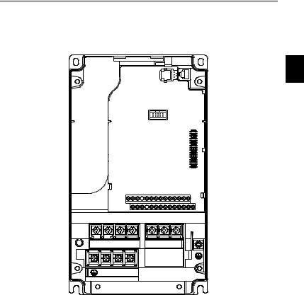
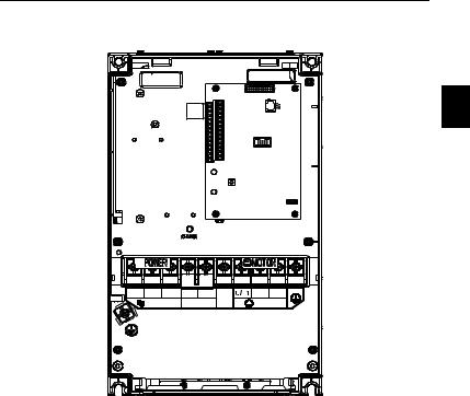
7.5 HP to 20 HP
(VFD055F23A/43B, VFD075F23A/43B, VFD110F23A/43A, VFD150F43A)
POWER |
3 MOTOR |
|
IM |
Control Terminal
Torque: 4Kgf-cm (3 in-lbf)
Wire: 12-24 AWG
Power Terminal
Torque: 30Kgf-cm (26 in-lbf) Wire: 12-8 AWG
Wire Type: Stranded copper only, 75° C
NOTE: If wiring of the terminal utilizes the wire with a 6AWG-diameter, it is thus necessary to use the Recognized Ring Terminal to conduct a proper wiring.
3-8 |
DELTA ELECTRONICS, INC. ALL RIGHTS RESERVED |
 VFD-F Series
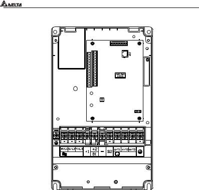
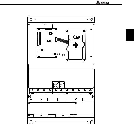
20 HP to 40 HP
(VFD150F23A, VFD185F23A/43A, VFD220F23A/43A, VFD300F43A)
3
R/L1 S/L2 T/L3 |
+1 |
+2 |
- |
|
V/T2 W/T3 |
POWER |
DC (+) |
DC ( -) |
IM |
MOTOR |
|
3 |
|||||
Control Terminal
Torque: 4Kgf-cm (3 in-lbf)
Wire: 12-24 AWG
Power Terminal
Torque: 30Kgf-cm (26 in-lbf) Wire: 8-2 AWG
Wire Type: Stranded copper only, 75° C
NOTE: If wiring of the terminal utilizes the wire with a 1AWG-diameter, it is thus necessary to use the Recognized Ring Terminal to conduct a proper wiring.
DELTA ELECTRONICS, INC. ALL RIGHTS RESERVED |
3-9 |
VFD-F Series
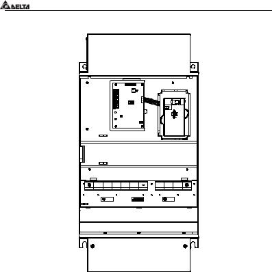
50 HP to 60 HP (VFD370F43A, VFD450F43A)
POWER
ALARM
CHARGE
R/L1 S/L2 T/L3 |
+1 +2 - |
U/T1 |
V/T2 2/T3 |
POWER |
|
IM |
MOTOR |
|
3 |
Control Terminal
Torque: 4Kgf-cm (3 in-lbf)
Wire: 12-24 AWG
Power Terminal
Torque: 57kgf-cm (49.5 in-lbf) min.
Wire Gauge: VFD370F43A: 3AWG
VFD450F43A: 2AWG
Wire Type: Stranded copper only, 75° C
3-10 |
DELTA ELECTRONICS, INC. ALL RIGHTS RESERVED |
VFD-F Series
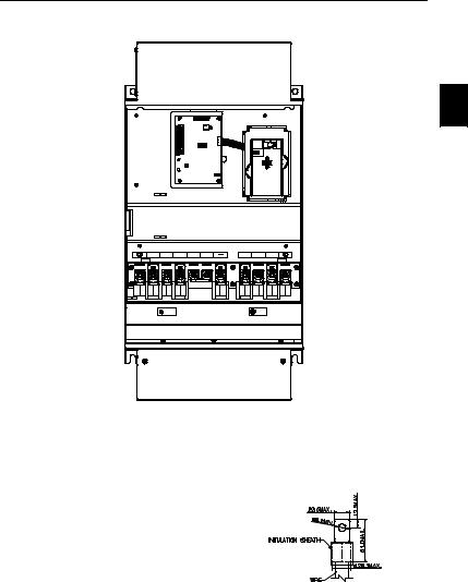
40 HP to 125 HP
(VFD300F23A, VFD370F23A, VFD550F43A, VFD750F43A, VFD900F43C)
3
POWER
ALARM
CHARGE
R/L1 S/L2 T/L3 |
+1 +2 |
U/T1 V/T2 W/T3 |
|
POWER |
Screw Torque: |
IM |
MOTOR |
200kgf-cm (173in-lbf) |
3 |
||
Control Terminal
Torque: 4Kgf-cm (3 in-lbf)
Wire: 12-24 AWG
Power Terminal
Torque: 200kgf-cm (173 in-lbf)
Wire Gauge: VFD300F23A, VFD550F43A: 1/0-4/0 AWG
VFD370F23A, VFD750F43A: 3/0-4/0 AWG, VFD900F43C: 4/0 AWG
Wire Type: Stranded copper only, 75°C
DELTA ELECTRONICS, INC. ALL RIGHTS RESERVED |
3-11 |
VFD-F Series
125 HP (VFD900F43A )
R/L1 S/L2 T/L3 +1 +2 |
U/T1 V/T2 W/T3 |
POWER |
M OT OR |
Control Terminal
Torque: 4Kgf-cm (3 in-lbf)
Wire: 12-24 AWG
Power Terminal
Torque: 200kgf-cm (173 in-lbf)
Wire Gauge: 4/0 AWG
Wire Type: Stranded copper only, 75°C
3-12 |
DELTA ELECTRONICS, INC. ALL RIGHTS RESERVED |
 VFD-F Series
150 HP (VFD1100F43A)
3
R/L1 S/L2 T/L3 +1 +2 |
U/T1 V /T2 W/T3 |
P OWER |
M OT OR |
Control Terminal
Torque: 4Kgf-cm (3 in-lbf)
Wire: 12-24 AWG
Power Terminal
Torque: 80kgf-cm (69 in-lbf) Wire Gauge: 300 MCM
Wire Type: Stranded copper only, 75°C
NOTE: It needs following additional terminal when wiring, and add insulation sheath on position where following figure shows.
DELTA ELECTRONICS, INC. ALL RIGHTS RESERVED |
3-13 |
VFD-F Series
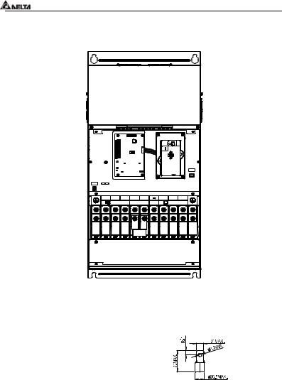
150 HP to 215 HP
(VFD1100F43C, VFD1320F43A, VFD1600F43A)
R/L1 S/L2 T/L3 |
+1 |
+2 |
DC(-) |
U/T1 V/T2 W/T3 |
|
POWER |
DC(+) |
IM |
MOTOR |
||
3 |
|||||
Control Terminal
Torque: 4Kgf-cm (3 in-lbf)
Wire: 12-24 AWG
Power Terminal
Torque: 300kgf-cm (260 in-lbf)
Wire Gauge: 1/0 AWG*2-300 MCM*2 Wire Type: Stranded copper only, 75°C
NOTE: It needs following additional terminal when wiring. The additional terminal dimension should comply with the following figure.
UNIT:mm
3-14 |
DELTA ELECTRONICS, INC. ALL RIGHTS RESERVED |
 VFD-F Series
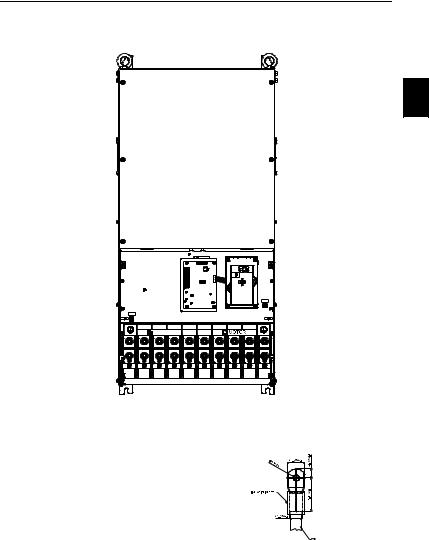
250 HP to 300 HP (VFD1850F43A, VFD2200F43A)
3
R/L1 S/L2 T/L3 |
+ |
- U/T1 V/T2 W/T3 |
POWER |
DC(+) |
DC(-) |
Control Terminal
Torque: 4Kgf-cm (3 in-lbf)
Wire: 12-24 AWG
Power Terminal
Torque: 408kgf-cm (354 in-lbf) Wire Gauge: 500 MCM (max)
Wire Type: Stranded copper only, 75°C
NOTE: It needs following additional terminal when wiring, and add insulation sheath on position where following figure shows.
DELTA ELECTRONICS, INC. ALL RIGHTS RESERVED |
3-15 |
VFD-F Series
3.5 Wiring Notes: PLEASE READ PRIOR TO INSTALLATION.
1. ! CAUTION: Do not connect the AC power to the U/T1, V/T2, W/T3 terminals, as it will damage the AC drive.
2. ! WARNING: Ensure all screws are tightened to the proper torque rating.
3.During installation, follow all local electrical, construction, and safety codes for the country the drive is to be installed in.
4.Ensure that the appropriate protective devices (circuit breaker or fuses) are connected between the power supply and AC drive.
5.Make sure that the leads are connected correctly and the AC drive is properly grounded. (Ground resistance should not exceed 0.1Ω.)
6.Use ground leads that comply with AWG/MCM standards and keep them as short as possible.
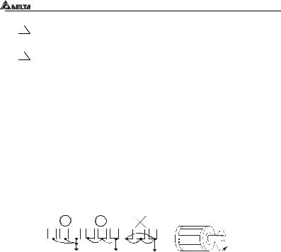
7.Multiple VFD-F units can be installed in one location. All the units should be grounded directly to a common ground terminal. The VFD-F ground terminals may also be connected in parallel, as shown in the figure below. Ensure there are no ground loops.
Forward running
8.When the AC drive output terminals U/T1, V/T2, and W/T3 are connected to the motor terminals U/T1, V/T2, and W/T3, respectively, the motor will rotate counterclockwise (as viewed from the shaft ends of the motor) when a forward operation command is received. To reverse the direction of motor rotation, switch over any of the two motor leads.
9.Make sure that the power source is capable of supplying the correct voltage and required current to the AC drive.
10.Do not attach or remove wiring when power is applied to the AC drive.
11.Do not inspect components unless inside “CHARGE” lamp is turned off.
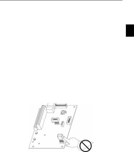
12.Do not monitor the signals on the circuit board while the AC drive is in operation.
3-16 |
DELTA ELECTRONICS, INC. ALL RIGHTS RESERVED |
 VFD-F Series
13.For the single-phase rated AC drives, the AC power can be connected to any two of the three input terminals R/L1, S/L2, T/L3. Note: This drive is not intended for the use with single-phase motors.
14.Route the power and control wires separately, or at 90°angle to each other.
15.If a filter is required for reducing EMI (Electro Magnetic Interference), install it as close
as possible to AC drive. EMI can also be reduced by lowering the Carrier Frequency. |
3 |
16.If the AC drive is installed in the place where a load reactor is needed, install the filter close to U/T1, V/T2, W/T3, side of AC drive. Do not use a Capacitor or L-C Filter (Inductance-Capacitance) or R-C Filter (Resistance-Capacitance), unless approved by Delta.
17.When using a GFCI (Ground Fault Circuit Interrupt), select current sensor with sensitivity of 200mA, and not less than 0.1-second detection to avoid nuisance tripping.
18.To improve the input power factor, to reduce harmonics and provide protection from AC line disturbances (surges, switching spikes, short interruptions, etc.), AC line reactor should be installed when the power supply capacity is 500kVA or more.
19.There are highly sensitive MOS components on the printed circuit boards. These components are especially sensitive to static electricity. To prevent damage to these components, do not touch these components or the circuit boards with metal objects or your bare hands.
DELTA ELECTRONICS, INC. ALL RIGHTS RESERVED |
3-17 |

VFD-F Series
3.6 Motor Operation Precautions
1.When using the AC drive to operate a standard 3-phase induction motor, notice that the energy loss is greater than for an inverter duty motor.
2.Avoid running a standard induction motor at low speed. Under these conditions, the motor temperature may rise above the motor rating due to limited airflow produced by the motor’s fan.
3.When the standard motor operates at low speed, the output load must be decreased.
4.If 100% output torque is desired at low speed, it may be necessary to use a special “inverter-duty” rated motor.
3-18 |
DELTA ELECTRONICS, INC. ALL RIGHTS RESERVED |
 VFD-F Series
CHAPTER 4 DIGITAL KEYPAD OPERATION
This chapter describes the various controls and indicators found on the digital keypad. The information in this chapter should be read and understood before performing the start–up procedures described in the chapter of parameter settings.
ª Description of the Keypad |
|
ª Description of Display |
|
ª Keypad Operation Modes & Programming Steps |
4 |
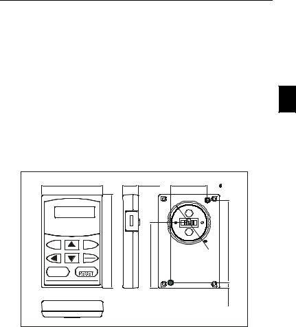
4.1 VFD-PU01
4.1.1 VFD-PU01 Dimensions: mm (inch)
73.0 [2.87]
JOG MODE
PROG
DATA
RUN STOP
|
19.0 [0.75] |
44.0 [1.73] |
M4* |
0.7(2X) |
|
|
|
||
[4.33] |
|
|
0 |
[3.82] |
|
|
|
? |
|
|
|
|
4 |
|
110.0 |
[3.03] |
|
. |
97.0 |
|
0 |
|||
|
|
|
[ |
|
|
|
|
1 |
|
|
|
|
. |
|
|
|
|
5 |
|
|
|
|
8 |
|
|
|
|
] |
|
|
77.0 |
|
|
|
|
|
|
|
6.5 [0.26] |
DELTA ELECTRONICS, INC. ALL RIGHTS RESERVED |
4-1 |
Loading...