


………………………………………………………………… ENGLISH …………………………………………………………………
This Instruction Sheet only provides descriptions for electrical specifications, general specifications, installation & wiring. Other detail infromation about programming and intructions, please see “DVP-PLC Application Manual: Programming”. For more information about the optional peripherals, please see individual product instuction sheet or “DVP-PLC Application Manual: Special I/O Modules”.
DVP-EH3 is an OPEN TYPE device and therefore should be installed in an enclosure free of airborne dust, humidity, electric shock and vibration. The enclosure should prevent non-maintenance staff from operating the device (e.g. key or specific tools are required for operating the enclosure) in case danger and damage on the device may occur.
Do NOT connect the AC main circuit power supply to any of the input/output terminals, or it may damage the PLC. Check all the wiring prior to power up. To prevent any electromagnetic noise, make sure the PLC is properly grounded  . Do NOT touch terminals when power on.
Product Profile & Dimension
1
2 |
|
|
|
|
3 |
|
|
|
|
4 |
|
|
|
|
5 |
|
|
|
|
6 |
|
|
|
|
7 |
|
|
13 |
12 |
|
|
|
||
|
|
2 |
15 |
16 |
|
X |
|
|
|
6 |
|
|
|
|
4. |
|
|
|
|
8
9
10
11
[ Figure 1 ]
14
90.0 |
80.0 |
Unit: mm
W1
W |
82.2 |
[ Figure 2 ] |
|
Model |
16EH00 |
|
20EH00 |
32EH00 |
|
40EH00 |
|
48EH00 |
|
64EH00 |
|
80EH00 |
|||
|
name |
R3/T3 |
|
R3/T3 |
|
R3/T3/M3 |
|
R3/T3 |
|
R3/T3 |
|
R3/T3 |
|
R3/T3 |
||
|
W |
|
113 |
|
113 |
|
143.5 |
|
158.8 |
174 |
|
|
212 |
|
276 |
|
|
W1 |
103 |
|
103 |
|
133.5 |
|
153.8 |
164 |
|
|
202 |
|
266 |
||
|
|
|
|
|
|
|
|
|
|
|
|
|
|
|
||
|
○1 |
COM2(RS-485) |
○7 |
Function card mounting hole |
|
○13 |
Function card port |
|
||||||||
|
○2 |
Run/Stop switch |
○8 |
POWER/RUN/BAT.LOW/ER |
|
○14 |
Communication port cover |
|||||||||
|
ROR Indicator |
|
|
|||||||||||||
|
○3 |
VR0/VR1 |
○9 |
I/O module connection port |
|
○15 |
Function card/memory card |
|||||||||
|
|
|
|
|
|
|
|
|
|
|
|
cover |
|
|
|
|
|
○4 |
COM1(RS-232) |
○10 |
Mounting screw |
|
|
○16 |
coverI/O module connection port |
||||||||
|
|
|
|
|
|
|
|
|
|
|
|
|||||
|
○5 |
Battery socket |
○11 |
Direct mounting hole |
|
|
|
|
|
|
|
|||||
|
|
|
|
|
|
|
|
|
|
|
|
|
||||
|
○6 |
Battery |
○12 |
Memory card port |
|
|
|
|
|
|
|
|
||||
|
|
|
|
|
|
|
|
|
|
|
|
|
|
|
|
|
- 1 -

Electrical Specifications
|
Model |
|
16EH |
20EH |
32EH |
32EH |
40EH |
48EH |
64EH |
80EH |
|
Item |
|
00 3 |
00 3 |
00 3 |
00M3 |
00 3 |
00 3 |
00 3 |
00 3 |
|
Power supply |
|
100 ~ 240VAC (-15% ~ 10%); 50/60Hz ± 5% |
|
|
|
||||
|
voltage |
|
|
|
|
|||||
|
|
|
|
|
|
|
|
|
|
|
|
Fuse capacity |
|
2A/250VAC |
|
|
|
|
|
|
|
|
Power |
|
50VA |
|
60VA |
|
80VA |
|||
|
consumption |
|
|
|
||||||
|
|
|
|
|
|
|
|
|
|
|
|
DC24V current |
|
500mA |
|
|
|
|
|
|
|
|
output |
|
|
|
|
|
|
|
|
|
|
Power supply |
|
DC24V output short circuit protection |
|
|
|
|
|||
|
protection |
|
|
|
|
|
||||
|
|
|
|
|
|
|
|
|
|
|
|
Voltage |
|
1,500VAC (Primary-secondary), 1,500VAC (Primary-PE), |
|
|
|||||
|
withstand |
|
500VAC (Secondary-PE) |
|
|
|
|
|
||
|
Insulation |
|
> 5MΩ at 500VDC (between all I/O points and ground) |
|
|
|||||
|
resistance |
|
|
|
||||||
|
|
|
|
|
|
|
|
|
|
|
|
|
|
ESD: 8KV Air Discharge |
|
|
|
|
|
||
|
Noise immunity |
|
EFT: Power Line: 2KV, Digital I/O: 1KV, Analog & Communication I/O: 250V |
|||||||
|
|
|
Damped-Oscillatory Wave: Power Line: 1KV, Digital I/O: 1KV, RS: 26MHz ~ |
|||||||
|
|
|
1GHz, 10V/m |
|
|
|
|
|
|
|
The diameter of grounding wire shall not be less than that of L, N terminal of Grounding the power supply. (When many PLCs are in use at the same time, please
make sure every PLC is properly grounded.)
|
Operation/ |
|
Operation: 0°C~55°C (temperature), 50~95% (humidity), pollution degree 2 |
||||||||||||||||
|
storage |
|
Storage: -25°C~70°C (temperature), 5~95% (humidity) |
|
|
|
|||||||||||||
|
Vibration/shock |
International standards: IEC61131-2, IEC 68-2-6 (TEST Fc)/ IEC61131-2 & |
|||||||||||||||||
|
resistance |
|
IEC 68-2-27 (TEST Ea) |
|
|
|
|
|
|
|
|
|
|
||||||
|
Weight (g) |
|
R: 500 |
|
R: 520 |
|
R: 652 |
|
644 |
R: 710 |
|
R: 748 |
|
R: 836 |
R: 948 |
||||
|
|
T: 480 |
|
T: 500 |
|
T: 612 |
|
T: 675 |
|
T: 688 |
|
T: 756 |
T: 848 |
||||||
|
|
|
|
|
|
|
|
|
|
||||||||||
|
|
|
|
|
|
|
|
|
|
|
|
|
|
|
|
|
|
||
|
|
|
|
|
|
|
|
Input Point |
|
|
|
|
|
|
|
|
|||
|
|
|
|
Spec. |
Two Differential |
|
|
24VDC single common port input |
|
||||||||||
|
Items |
|
|
inputs (200kHz) |
|
|
200kHz |
|
|
10kHz |
|
Normal input |
|||||||
|
Input wiring type |
|
Independent |
|
|
Change wiring from S/S to SINK or SOURCE |
|||||||||||||
|
|
wiring |
|
|
|
||||||||||||||
|
|
|
|
|
|
|
|
|
|
|
|
|
|
|
|
|
|
||
|
Input voltage (± 10%) |
|
5~24VDC |
|
|
|
|
|
24VDC |
|
|
|
|||||||
|
Input point |
|
|
#1 |
|
|
|
#2 |
|
|
#3 |
|
|
|
#4 |
||||
|
configuration |
|
|
|
|
|
|
|
|
|
|
|
|
|
|
|
|
|
|
|
|
|
|
|
|
|
|
|
|
|
|
|
|
|
|
|
|
|
|
|
Input impedance |
|
4.7K Ohm |
|
|
3.3K Ohm |
|
4.7K Ohm |
|
4.7K Ohm |
|||||||||
|
Active |
|
Off → On |
|
> 1mA (5V) |
|
> 2mA (15V) |
> 2mA (15V) |
|
> 2mA(15V) |
|||||||||
|
Level |
|
On → Off |
|
< 0.4mA (2V) |
|
< 0.5mA (5V) |
< 0.5mA (5V) |
|
< 0.5mA(5V) |
|||||||||
|
Response |
|
Off → On |
|
< 150ns |
|
|
< 150ns |
|
|
|
< 8μs |
|
< 10ms |
|||||
|
time #5 |
|
On → Off |
|
< 3μs |
|
|
|
< 3μs |
|
|
|
< 60μs |
|
< 20ms |
||||
|
|
|
|
|
|
|
|
|
|
|
|
|
|
|
|
|
|
|
|
#1 In DVP32EH00M3, the bandwidth of two differential input points X0, X1, X4, and X5 is 200kHz.
#2 The bandwidth of input points X0, X1, X4, X5, X10, X11, X14, and X15 is 200kHz. #3 The bandwidth of input points X2, X3, X6, X7, X12, X13, X16, and X17 is 10kHz. #4 The X20 and above are normal input points.
#5 The filter times of X0~X7 and X10~X17 can be adjusted by D1020 and D1021 respectively within 10~60ms.
- 2 -

Output Point
|
Two |
Single common port |
|
|
|||
Spec. |
transistor output |
|
Single common |
||||
differential |
|
||||||
Items |
outputs #1 |
High speed |
#2 |
Low speed |
Normal |
port relay output |
|
|
|
|
#3 |
|
|||
Max. frequency |
|
|
|
|
output |
Load ON/OFF |
|
200kHz |
200kHz |
|
10kHz |
#4 |
|||
|
|
|
control |
||||
|
|
|
|
|
|
||
Minimum load |
|
|
- |
|
|
2mA/DC power |
|
|
|
|
|
supply |
|||
|
|
|
|
|
|
||
Working voltage |
5VDC |
|
5 ~ 30VDC |
|
250VAC, |
||
|
|
30VDC |
|||||
|
|
|
|
|
|
||
Insulation |
Line Driver |
Photo coupler isolation |
Magnetic |
||||
isolation |
|||||||
|
|
|
|
|
|
||
Resistive |
< 25mA |
0.5A/1 point (4A/COM) |
2A/1 point |
||||
(5A/COM) |
|||||||
Maximum Inductive |
|
|
|
|
|
||
- |
12W (24VDC) |
|
#5 |
||||
load |
|
|
|
|
|
|
|
Lamp |
- |
|
2W(24VDC) |
|
20WDC/100WAC |
||
Max. output response |
0.2μs |
0.2μs |
|
Off On: 20μs |
10ms |
||
time |
|
On Off: 30μs |
|||||
|
|
|
|
||||
Over-current protection |
N/A |
#1 DVP32EH00M3 supports two differential outputs (Y0~Y3). #2 The frequency of output points Y0~Y4 and Y6 is 200kHz. #3 The frequency of output points Y5 and Y7 is 10kHz.
#4 The Y10 and above are normal output points. #5: Life curves
|
3000 |
|
120VAC Resistive |
|
|
|||
|
|
30VDC Inductive(t=7ms) |
|
|||||
|
2000 |
|
|
|||||
|
|
|
240VAC Inductive(cosψ=0.4) |
|||||
|
1000 |
|
|
|||||
|
|
|
120VAC Inductive(cosψ=0.4) |
|||||
0)3 |
|
|
|
|||||
500 |
|
|
|
|
|
|
|
|
X1( |
300 |
|
|
|
|
|
|
|
no |
200 |
|
|
|
|
|
|
|
ita |
100 |
|
|
|
|
|
|
|
re |
30VDC |
|
|
|
|
|||
|
|
|
|
|
||||
Op |
50 |
Inductive |
|
|
|
|
||
|
30 |
|
(t=40ms) |
|
|
|
|
|
|
20 |
|
|
|
|
|
|
|
|
0.1 |
0.2 |
0.3 |
0.5 |
0.7 |
1 |
2 |
[ Figure 3 ] |
|
|
Contact Current(A) |
|
|||||
|
|
|
|
|||||
Installation
Please install the PLC in an enclosure with sufficient space
around it to allow heat dissipation, as shown in the figure.
y Direct Mounting: Please use M4 screw according to the dimension of the product.
y DIN Rail Mounting: When mounting the PLC to 35mm DIN rail, be sure to use the retaining clip to stop any side-to-side movement of the PLC and reduce the chance of wires being loose. The retaining clip is at the bottom of the PLC. To secure the PLC to DIN rail, pull
down the clip, place it onto the rail and gently push it up. To remove the PLC, pull the retaining clip down with a flat screwdriver and gently remove the PLC from DIN rail, as shown in the figure.
Wiring
- 3 -

1.Use O-type or Y-type terminal. See the figure in the right hand side for its specification. PLC terminal screws should be tightened to 9.50 kg-cm (8.25 in-Ibs) and please use only 60/75ºC copper conductor.
Below 
 6.2 mm


To suit M3.5
screw terminals Below 


6.2 mm 


2.DO NOT wire empty terminal. DO NOT place the input signal cable and output power cable in the same wiring circuit.
3.DO NOT drop tiny metallic conductor into the PLC while screwing and wiring. Tear off the sticker on the heat dissipation hole for preventing alien substances from dropping in, to ensure normal heat dissipation of the PLC.
Safety Wiring
In PLC control system, many devices are controlled at the same time and actions of any device could influence each other, i.e. breakdown of any device may cause the breakdown of the entire auto-control system and danger. Therefore, we suggest you wire a protection circuit at the power supply input terminal. See the figure below.
|
|
|
[ Figure 4 ] |
○1 |
AC power supply:100 ~ 240VAC, 50/60Hz |
○2 |
Breaker |
○3 Emergency stop: This button cuts off the system power supply when accidental emergency takes place.
○4 |
Power indicator |
○5 |
AC power supply load |
|
|
|
|
○6 |
Power supply circuit protection fuse (2A) |
○7 |
DVP-PLC (main processing unit) |
|
|
|
|
○8 |
DC power supply output: 24VDC, 500mA |
|
|
|
|
|
|
Power Supply
The power input type for DVP-EH3 series is AC input. When operating the PLC, please note the following points:
1.The input voltage should be current and its range should be 100 ~ 240VAC. The power should be connected to L and N terminals. Wiring AC110V or AC220V to +24V terminal or input terminal will result in serious damage on the PLC.
2.The AC power input for PLC MPU and I/O modules should be ON or OFF at the same time.
3.Use wires of 1.6mm (or longer) for the grounding of PLC MPU.
4.The power shutdown of less than 10 ms will not affect the operation of the PLC. However, power shutdown time that is too long or the drop of power voltage will stop the operation of the PLC and all outputs will go OFF. When the power returns to normal status, the PLC will automatically resume operation. (Care should be taken on the latched auxiliary relays and registers inside the PLC when programming).
-4 -
5.The +24V output is rated at 0.5A from MPU. DO NOT connect other external power supplies to this terminal. Every input terminal requires 6 ~ 7mA to be driven; e.g. the 16-point input will require approximately 100mA. Therefore, +24V terminal cannot give output to the external load that is more than 400mA.
Input Point Wiring
There are 2 types of DC inputs, SINK and SOURCE. (See the example below. For detailed point configuration, please refer to the specification of each model.)
yDC Signal IN – SINK mode Input point loop equivalent circuit
+24V |
24G |
S /S |
X0 |
X1 |
24V DC
[ Figure 5 ]
yDC Signal IN – SOURCE mode Input point loop equivalent circuit
+24V |
24V DC |
|
24G |
||
|
||
S/S |
|
|
X0 |
|
|
X1 |
[ Figure 6 ] |
|
|
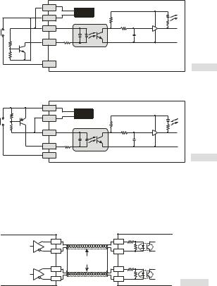
Wiring of Differential Input
X0 ~ X1 and X4 ~ X5 of DVP32EH00M3 are all high-speed input circuit and others are DC24V input. The working frequency of high-speed input circuit can reach up to 200kHz and is mainly for connecting to differential (double-wire) LINE DRIVER output circuit.
y Wiring in a high-speed, high-noise environment
Encoder output |
DVP32EH00M3 high-speed input |
|
A + |
X0+ |
|
A |
|
|
A - |
X0- |
|
Differential output |
Twisted pair |
|
cable |
|
|
|
|
|
B + |
X1+ |
|
B |
|
|
B - |
X1- |
[ Figure 7 ] |
|
|
|
In an environment with low noise and frequency less than 50kHz, use DC5V/DC24V single-ended SINK/SOURCE input.
- 5 -
 Loading...