


DVP-SX2
2011-04-12
5011696701-SX21
..
..
DVP-1150070-02
………………………………………………………………… ENGLISH ……………………………………………………………………
Thank you for choosing Delta DVP-SX2. DVP-SX2 is a 20-point (8DI + 6 DO + 4AI +
2AO) PLC MPU, offering various instructions and is with 16k steps program memory,
able to connect with all Slim series extension models, including digital input/output (max.
480 input/output extension points), analog modules (A/D, D/A transformation and
temperature units) and all kinds of new high-speed extension modules. Its 2-group
high-speed (100kHz) pulse outputs and the one new 2-axis interpolation instructions
satisfy all kinds of applications. DVP-SX2 is small in size and easy to install.
a This instruction sheet provides only information on the electrical specification,
general functions, installation and wiring. For detailed program design and applicable
instructions for DVP-SX2, please refer to “DVP-SX2 Operation Manual:
Programming”. For details on the optional peripheral, please refer to the instruction
sheet enclosed in the package.
a This is an OPEN TYPE PLC. The PLC should be kept in an enclosure away from
airborne dust, humidity, electric shock risk and vibration. Also, it is equipped with
protective methods such as some special tools or keys to open the enclosure, in
order to prevent hazard to users or damage on the PLC.
a DO NOT connect the AC main circuit power supply to any of the input/output
terminals, or it may damage the PLC. Check all the wiring prior to power up. To
prevent any electromagnetic noise, make sure the PLC is properly grounded .
DO NOT touch terminals when power on.
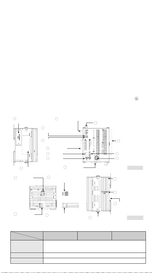
Product Profile
1
Left-side module
connection port
2
Nameplate
14
COM2 port
(RS-485)
3
POWER/RUN/ERROR/USB indicator
4
COM1 communication
indicator (RS-232)
5
COM2 communication
indicator (RS-485)
6
I/O indicator
7
USB port
8
VR0/VR1
9
DIN rail clip
16
3PIN removable terminal
(standard component)
10
Direct fastening hole
V0+
I0+
VI0-
V1+
I1+
VI1-
V2+
I2+
VI2-
V3+
I3+
VI3-
FE
VO0
IO0
VO1
IO1
AG
11
I/O terminal
12
RUN/STOP switch
13
COM1 port
(RS-232)
I/O module
18
positioning hole
[ Figure 1 ]
15
Power input
port
17
Power input connection
cable (standard component)
Electrical Specifications
Model
Item
Power supply voltage
Inrush current Max. 7.5A@24VDC
Fuse capacity 2.5A/30VDC, Polyswitch
DVP20SX211R DVP20SX211T DVP20SX211S
24VDC (-15% ~ 20%)
(with counter-connection protection on the polarity of DC input power)
DVPPS01(PS02): input 100-240VAC, output 24VDC/1A(PS02: 2A)
- 1 -
21
I/O module fastening clip
19
I/O module
connection port
20
Mounting slot
(35mm)
[ Figure 2 ]
Model
Item
DVP20SX211R DVP20SX211T DVP20SX211S
Power consumption 4.7W 4W 4W
Insulation resistance > 5MΩ (all I/O point-to-ground: 500VDC)
ESD: 8KV Air Discharge
Noise immunity
Grounding
Operation / storage
Vibration / shock
resistance
Weight (g) 243g 224g 227g
Spec.
Items
EFT: Power Line: 2KV, Digital I/O: 1KV, Analog & Comm. I/O: 1KV
RS: 26MHz ~ 1GHz, 10V/m
The diameter of grounding wire cannot be smaller than the wire
diameter of terminals 24V and 0V (All DVP units should be grounded
directly to the ground pole).
Operation: 0°C ~ 55°C (temp.), 50 ~ 95% (humidity), Pollution degree2
Storage: -25°C ~ 70°C (temp.), 5 ~ 95% (humidity)
International standards: IEC61131-2, IEC 68-2-6 (TEST
Fc)/IEC61131-2 & IEC 68-2-27 (TEST Ea)
Input Point
24VDC (-15% ~ 20%) single common port input
Input No. X0, X2 X1, X3 X4 ~ X7
Input type DC (SINK or SOURCE)
Input Current (± 10%) 24VDC, 5mA
Input impedance 4.7K Ohm
Action level
Response
time
Filter time Adjustable within 0 ~ 20ms by D1020 (Default: 10ms)
Spec.
Items
OffOn > 15VDC
OnOff < 5VDC
OffOn < 2.5μs < 10μs < 20us
OnOff < 5μs < 20μs < 50us
Output Point
Relay Transistor
Output No. Y0 ~ Y5 Y0, Y2 Y1, Y3 Y4, Y5
Max. frequency 1Hz 100kHz 10kHz 1kHz
Working voltage 250VAC, < 30VDC
SX211T: 0.5A/1 point (3A/ZP)
SX211S: 0.3A/1 point (1.8A/UP)
Max. load
Resistive 1.5A/1 point (5A/COM)
Inductive
#2
5 ~ 30VDC
15W (30VDC)
#1
Lamp 20WDC/100WAC 2.5W (30VDC)
Response
time
#1: DVP20SX211T: UP, ZP must work with external auxiliary power supply 24VDC (-15% ~
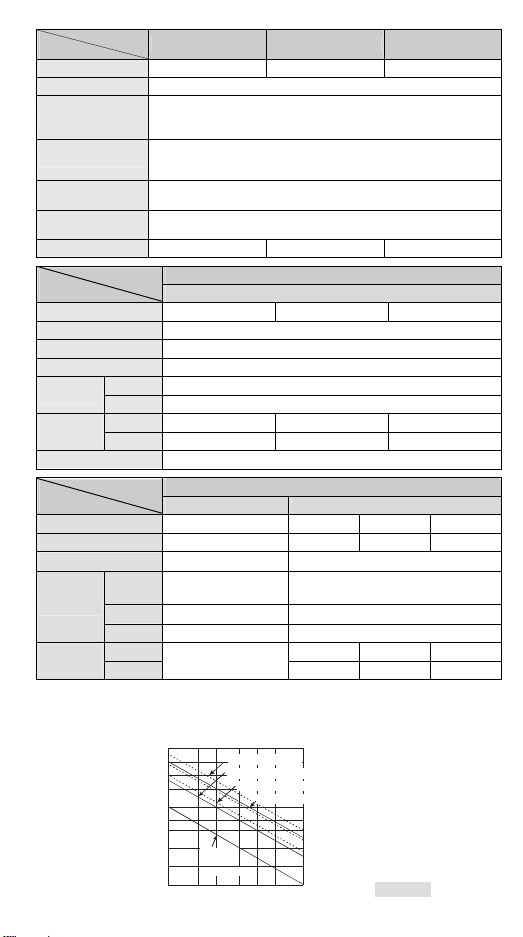
#2: Life curves
OffOn 2μs 20μs 100μs
OnOff
Approx. 10 ms
3μs 30μs 100μs
+20%), rated consumption approx. 3mA/point.
DVP20SX211S: UP, ZP must work with external auxiliary power supply 5~30VDC, rated
consumption approx. 5mA/point.
3000
2000
1000
)
3
0
500
1
X
300
(
n
200
o
i
t
a
100
r
e
p
O
50
0.1
120VAC Resistive
30VDC Inductive(t=7ms)
240VAC Inductive(cos 0.4)ψ=
30VDC
Inductiv e
( t=40 ms)
0.2
0.5
0.3 0.7
120VAC Inductive(cos =0.4)
12
Contact
Current(A)
ψ
[ Fig ure 3 ]
- 2 -
A/D and D/A Specifications
Items
Analog I/O range ±10V ±20mA 4 ~ 20mA#1±10V 0 ~ 20mA 4 ~ 20mA
Digital conversion
range
Resolution #2 12-bit
Input impedance > 1MΩ 250Ω -
Output impedance - 0.5Ω or lower
Tolerance carried
impedance
Overall accuracy
Response time 2ms (set up in D1118)
Absolute input
range
Digital data format 2’s complement of 16-bit, 12 significant bits
Average function Provided (set up in D1062)
Isolation method No Isolation between digital circuit and analog circuit
Protection
#1: Please refer to the detailed explanation of D1115.
#2: Resolution formula
Analog Input (A/D) Analog Output (D/A)
Voltage Current Voltage Current
20V
5mV( =
#3: When the scan period is longer than 2ms or the set value, the setting will follow the scan
period.
#4: When the scan period is longer than 2ms, the setting will follow the scan period.
#5: When the sampling range is “1”, the present value will be read.
4000
Analog Input (A/D) Analog Output (D/A)
Voltage Current Volt age Current
±2,000 ±2,000 0 ~ +2,000 ±2,000 0 ~ +4,000 0 ~ +4,000
- > 5KΩ < 500Ω
Non-linear accuracy: ±1% of full scale within the range of PLC operation
temperature
Maximum deviation: ±1% of full scale at 20mA and +10V
#3
2ms
#4
±15V ±32mA -
#5
-
Voltage output has short circuit protection, but a long period of short
circuit may cause internal wire damage and open circuit of current output.
μΑ(10 =
40mA
4000
)
5mV( =
)
20V
4000
)
μΑ(5 =
20mA
4000
)
#1
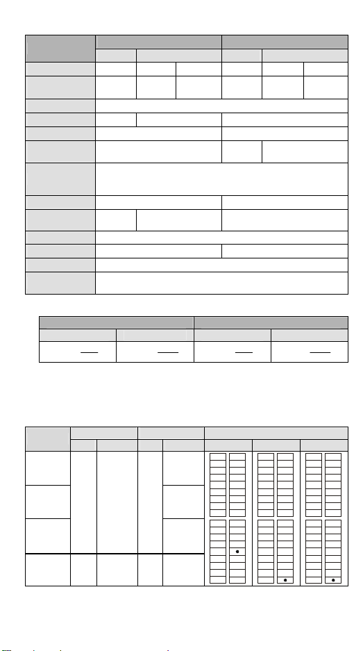
I/O Configuration
Model
Input Output
Point Type Point Type
20SX211R Relay
20SX211T
8
20SX211S
SX2-R/T/S 4
DC
(Sink Or
Source)
Analog
Input
6
2
NPN
Transistor
PNP
Transistor
Analog
output
I/O configuration
Relay NPN PNP
V0+
S/S
V0+
S/S
I0+
X0
VI0-
V1+
I1+
VI1-
V2+
I2+
VI2-
V3+
I3+
VI3-
FE
VO0
VO1
IO1
AG
I0+
X1
VI0-
X2
V1+
I1+
X3
X4
VI1-
X5
V2+
X6
I2+
X7
VI2-
C0
V3+
Y0
I3+
Y1
VI3-
Y2
FE
VO0
C1IO0
Y3
VO1
Y4
IO1
Y5
AG
V0+
X0
X1
VI0X2
V1+
X3
X4
VI1X5
V2+
X6
X7
VI2-
UP
V3+
ZP
Y0
VI3Y1
Y2
VO0
Y3IO0
Y4
VO1
Y5
IO1
S/S
I0+
X0
X1
X2
I1+
X3
X4
X5
I2+
X6
X7
UP
I3+
ZP
Y0
FE
Y1
Y2
Y3IO0
Y4
Y5
AG
Dimension & Installation
Please install the PLC in an enclosure with sufficient space around it to allow heat
dissipation, as shown in the [Figure 5].
- 3 -

Direct Mounting: Please use M4 screw according to the dimension of the product.
DIN Rail Mounting: When mounting the PLC to 35mm DIN rail, be sure to use the
retaining clip to stop any side-to-side movement of the PLC and reduce the chance of
wires being loose. The retaining clip is at the bottom of the PLC. To secure the PLC to
DIN rail, pull down the clip, place it onto the rail and gently push it up. To remove the
PLC, pull the retaining clip down with a flat screwdriver and gently remove the PLC from
DIN rail.
109.4
70
53.2
V0+
I0+
VI0-
V1+
I1+
VI1-
V2+
I2+
VI2-
V3+
I3+
VI3-
101
FE
VO0
IO0
VO1
IO1
AG
3 90 3
Unit: mm
[ Figu re 4 ]
Wiring
1. Use 22-16AWG (1.5mm) single or multiple core wire
on I/O wiring terminals. See the figure in the right hand
side for its specification. PLC terminal screws should be
tightened to 1.90 kg-cm (1.65 in-lbs) and please use only
60/75ºC copper conductor.
2. DO NOT wire empty terminal and place the I/O signal cable in the same wiring
circuit.
3. DO NOT drop tiny metallic conductor into the PLC while screwing and wiring. Tear
off the sticker on the heat dissipation hole for preventing alien substances from
dropping in, to ensure normal heat dissipation of the PLC.
Safety Wiring
Since DVP-SX2 is only compatible with DC power supply, Delta power supply modules
(DVPPS01/DVPPS02) are suitable power supplies for DVP-SX2. Users are suggested
to install the protection circuit at the power supply terminal to protect DVPPS01 or
DVPPS02. See the figure below.
22-16AWG
< 1.5mm
○1 AC power supply:100 ~ 240VAC, 50/60Hz ○
Emergency stop: This button cuts off the system power supply when accidental
○3
emergency takes place.
○4 Power indicator ○
2
Breaker
5
AC power supply load
- 4 -
○6 Power supply circuit protection fuse (2A) ○
○8 DC power supply output: 24VDC, 500mA ○
7
DVPPS01/DVPPS02
9
DVP-PLC (main processing unit)
○10 Digital I/O module
Power Supply
The power input of DVP-SX2 series is DC. When operating DVP-SX2 series, please
note the following points:
1. The power is connected to the two terminals, 24VDC and 0V, and the range of power
is 20.4 ~ 28.8VDC. If the power voltage is less than 20.4VDC, PLC will stop running,
all outputs will go “Off” and ERROR indicator will flash continuously.
2. The power shutdown of less than 10 ms will not affect the operation of the PLC.
However, power shutdown time that is too long or the drop of power voltage will stop
the operation of the PLC and all outputs will go OFF. When the power returns to
normal status, the PLC will automatically resume operation. (Care should be taken
on the latched auxiliary relays and registers inside the PLC when programming).
Input Point Wiring
There are 2 types of DC inputs, SINK and SOURCE. (See the example below. For
detailed point configuration, please refer to the specification of each model.)
DC Signal IN – SINK mode
Input point loop equivalent circuit
+24V
24G
S/S
X0
X1
[ Fig ure 7 ]
DC Signal IN – SOURCE mode
Input point loop equivalent circuit
+24V
24G
S/S
X0
X1
[ Figure 8 ]
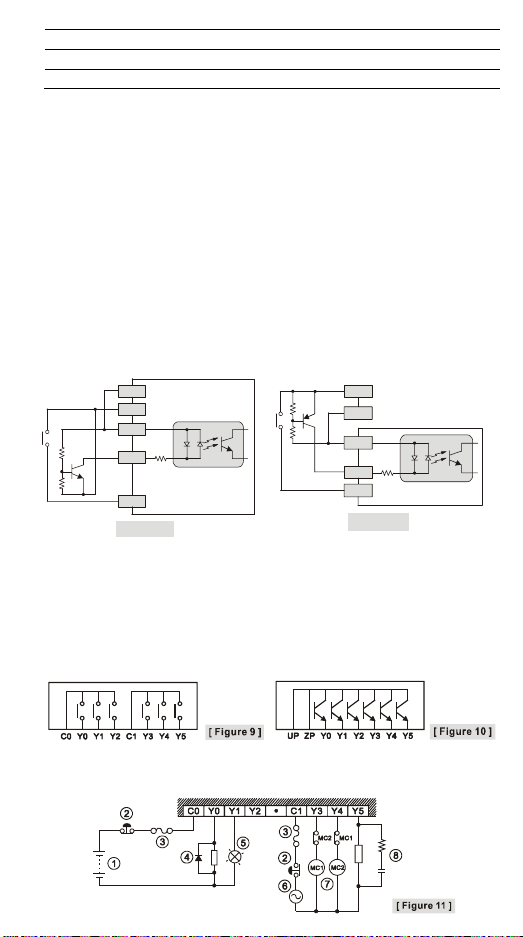
Output Point Wiring
1. DVP-SX2 series have three output modules, relay and transistor (NPN/PNP). Be
aware of the connection of shared terminals when wiring output terminals.
2. Output terminals, Y0, Y1, and Y2, of relay models use C0 common port; Y3, Y4, and
Y5 use C1 common port; as shown in the [Figure 9]. When output points are enabled,
their corresponding indicators on the front panel will be on.
3. Output terminals, Y0 ~Y5 of transistor (NPN/PNP) models use UP, ZP common port;
as shown in the [Figure 10].
4. Isolation circuit: The optical coupler is used to isolate signals between the circuit
inside PLC and input modules.
Relay (R) output circuit wiring
- 5 -
 Loading...