


DVP-1050030-02
………………………………………………………………… ENGLISH ……………………………………………………………………
Thank you for choosing Delta DVP-SV. DVP-SV is a 28-point (16 input + 12 output) PLC MPU, offering various instructions and with 16k steps program memory, able to connect to all DVP-SS/SA/SX/SC/SV series extension models, including digital I/O (max. 512 points), analog modules (for A/D, D/A conversion and temperature measurement) and all kinds of high-speed extension modules. 4 groups of high-speed (200kHz) pulse output and 2 two-axis interpolation instructions satisfy all kinds of applications. DVP-SV is small in size and easy to install.
This instruction sheet only provides introductory information on electrical specifications, general specifications, installation and wiring. For detalied infromation on programming and intructions, please refer to “DVP-PLC Application Manual: Programming”. For information about optional peripherals, please see individual product instuction sheet or “DVP-PLC Application Manual: Special Modules”.
This is an OPEN-TYPE device and therefore should be installed in an enclosure free of airborne dust, humidity, electric shock and vibration. The enclosure should prevent non-maintenance staff from operating the device (e.g. key or specific tools are required to open the enclosure) in case danger and damage on the device may occur.
DO NOT connect input AC power supply to any of the I/O terminals; otherwise serious damage may occur. Check all the wiring again before switching on the power. Make sure the groud terminal  is correctly grounded in order to prevent electromagnetic interference. DO NOT touch any internal when the power is switched off.
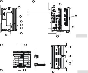
Product Profile
1 Left-side module |
9 POWER/RUN/BAT.LOW/ERROR indicator |
|
connection port |
10 |
Direct fastening hole |
|
||
3 COM1(RS-232) receiving |
|
|
communication (Rx) indicator |
|
|
4 |
COM2(RS-485) sending |
11 I/O terminal |
|
communication (Tx) indicator |
|
5I/O indicator 
6RUN/STOP switch 
7 |
VR0: M1178 enabled/D1178 |
12 |
COM1(RS-232) |
|
program I/O |
||
|
corresponding value |
|
|
|
|
communication |
|
|
|
|
|
8 |
VR1: M1179 enabled/D1179 |
|
port |
2 Nameplate |
corresponding value |
13 DIN rail clip |
[ Figure 1 ] |
|
14 |
COM2(RS-485) |
|
communication port |
|
(Master/Slave) |
163PIN removable terminal (standard component)
 18 I/O module positioning hole
 19 I/O module connection port
20 Mounting slot (35mm)
15 Power input port |
17 Power input connection |
21 I/O module fastening clip [ Figure 2 ] |
|
cable (standard component) |
- 1 -
Electrical Specifications
Model
DVP28SV11R DVP28SV11T
Item
Power supply |
24VDC (-15% ~ 20%) (with counter-connection protection on the |
voltage |
polarity of DC input power) |
Inrush current |
Max. 2.2A@24VDC |
Fuse capacity |
2.5A/30VDC, Polyswitch |
Power consumption |
6W |
Insulation resistance |
> 5MΩ (all I/O point-to-ground: 500VDC) |
|
ESD (IEC 61131-2, IEC 61000-4-2): 8kV Air Discharge |
|
EFT (IEC 61131-2, IEC 61000-4-4): Power Line: 2kV, Digital I/O: 1kV, |
Noise immunity |
Analog & Communication I/O: 1kV |
|
Damped-Oscillatory Wave: Power Line: 1kV, Digital I/O: 1kV |
|
RS (IEC 61131-2, IEC 61000-4-3): 26MHz ~ 1GHz, 10V/m |
The diameter of grounding wire shall not be less than that of the wiring Grounding terminal of the power. (When PLCs are in use at the same time, please
make sure every PLC is properly grounded.)
|
Operation: 0ºC ~ 55ºC (temperature); 50 ~ 95% (humidity); |
||
Operation / storage |
pollution degree 2 |
|
|
|
Storage: -25ºC ~ 70ºC (temperature); 5 ~ 95% (humidity) |
||
|
UL508 |
|
|
Agency approvals |
European community EMC Directive 89/336/EEC and Low Voltage |
||
|
Directive 73/23/EEC |
|
|
Vibration / shock |
International standards: IEC61131-2, IEC 68-2-6 (TEST |
||
immunity |
Fc)/IEC61131-2 & IEC 68-2-27 (TEST Ea) |
|
|
Weight (g) |
260 |
|
240 |
|
|
|
|
Input Point
|
Spec. |
24VDC single common port input |
|||
Items |
|
200kHz |
20kHz |
10kHz |
|
Input No. |
|
X0, X1, X4, X5 |
X10, X11, X14, X15 |
X6, X7, X12, X13, |
|
|
X16, X17 |
||||
|
|
|
|
||
Input voltage (±10%) |
|
24VDC, 5mA |
|
||
Input impedance |
4.7kΩ |
3.3kΩ |
4.7kΩ |
||
Action level |
Off On |
> 4mA (16.5V) |
> 6mA (18.5V) |
> 4mA (16.5V) |
|
On Off |
< 1.5mA (8V) |
< 2.2mA (8V) |
< 1.5mA (8V) |
||
|
|||||
Response |
Off On |
< 150ns |
< 3.5μs |
< 8μs |
|
time |
On Off |
< 3μs |
< 20μs |
< 60μs |
|
|
|||||
Filter time |
|
Adjustable within 10 ~ 60ms by D1020, D1021 (Default: 10ms) |
|||
Output Point
|
Items |
Spec. |
Relay |
|
Transistor |
|
|
|
|
|
High-speed |
Low-speed |
|
||
|
Output No. |
|
Y0 ~ Y7, Y10 ~ Y13 |
Y0 ~ Y4, Y6 |
Y5, Y7, Y10 |
Y14 ~ Y17, |
|
|
|
~ Y13 |
Y20 ~ #1 |
||||
|
|
|
|
|
|||
|
Max. frequency |
1Hz |
200kHz |
10kHz |
1kHz |
||
|
Working voltage |
250VAC, < 30VDC |
|
30VDC |
|
|
|
|
|
|
|
0.3A/1 point @ 40°C; When the output of |
|||
|
Max. load |
Resistive |
1.5A/1 point (5A/COM) |
Y0, Y1, Y10 and Y11 is high-speed pulse, |
|||
|
|
|
|
Y0,Y1, Y10 and Y11 = 30mA |
|||
|
|
|
- 2 - |
|
|
|
|

Output Point
|
Spec. |
Relay |
|
Transistor |
|
|
Items |
|
High-speed |
Low-speed |
|||
|
|
|||||
|
Inductive |
#2 |
|
9W (30VDC) |
|
|
Max. load |
|
|
|
|||
Lamp |
20WDC/100WAC |
|
1.5W (30VDC) |
|
||
|
|
|
||||
Response |
Off On |
Approx. 10ms |
0.2μs |
20μs |
<100μs |
|
time |
On Off |
0.2μs |
30μs |
<100μs |
||
|
||||||
#1: Please refer to “I/O Terminal Layout” for the max. X/Y No. on each model. |
|
|||||
#2: Life curves |
|
|
|
|
|
|
|
3000 |
|
|
120VAC Resistive |
|
|
|||
|
2000 |
|
|
30VDC Inductive(t=7ms) |
|
||||
|
|
|
240VAC Inductive(cosψ=0.4) |
|
|||||
|
1000 |
|
|
|
|||||
|
|
|
|
120VAC Inductive(cosψ=0.4) |
|
||||
) |
|
|
|
|
|
||||
30 |
500 |
|
|
|
|
||||
|
|
|
|
|
|
|
|
||
1X( |
300 |
|
|
|
|
|
|
|
|
no |
200 |
|
|
|
|
|
|
|
|
ait |
100 |
|
|
|
|
|
|
|
|
re |
30VDC |
|
|
|
|
|
|||
|
|
|
|
|
|
||||
pO |
50 |
Inductive |
|
|
|
|
|
||
|
|
|
(t=40ms) |
|
|
|
Contact |
|
|
|
|
|
|
|
|
|
|
[ Figure 3 ] |
|
|
0.1 |
0.2 |
0.3 |
0.5 |
0.7 |
1 |
2 |
Current(A) |
|
|
|
||||||||
I/O Configuration
|
Model |
Power |
|
Input |
|
Output |
|
I/O configuration |
|
|
|
Point |
Type |
Point |
Type |
Relay |
Transistor |
||||
|
|
|
||||||||
|
|
|
|
|
|
|
S/S |
C0 |
S/S |
C0 |
|
|
|
|
|
|
|
X0 |
Y0 |
X0 |
Y0 |
|
|
|
|
|
|
|
X1 |
Y1 |
X1 |
Y1 |
DVP28SV11R |
|
|
|
|
Relay |
X2 |
Y2 |
X2 |
C1 |
|
|
|
|
|
X3 |
C1 |
X3 |
Y2 |
|||
|
|
|
|
|
|
|
X4 |
X4 |
Y3 |
|
|
|
|
|
DC |
|
|
X5 |
Y3 |
X5 |
C2 |
|
|
|
|
|
|
X6 |
Y4 |
X6 |
Y4 |
|
|
|
|
16 |
(Sink Or |
12 |
|
X7 |
Y5 |
X7 |
Y5 |
|
|
24VDC |
|
S/S |
C2 |
S/S |
C3 |
|||
|
|
|
Source) |
|
|
|||||
|
|
|
|
|
|
X10 |
Y6 |
X10 |
Y6 |
|
|
|
|
|
|
|
|
X11 |
Y7 |
X11 |
Y7 |
|
|
|
|
|
|
|
X12 |
Y10 |
X12 |
C4 |
DVP28SV11T |
|
|
|
|
Transistor |
X13 |
|
X13 |
||
|
|
|
|
X14 |
C3 |
X14 |
Y10 |
|||
|
|
|
|
|
|
|
X15 |
Y11 |
X15 |
Y11 |
|
|
|
|
|
|
|
X16 |
Y12 |
X16 |
Y12 |
|
|
|
|
|
|
|
X17 |
Y13 |
X17 |
Y13 |
Installation |
|
|
|
|
|
|
|
|
||
|
|
70 |
3 |
|
|
|
|
|
|
|
|
|
53.2 |
|
|
|
|
|
|
|
|
|
|
|
|
|
|
|
|
|
|
|
109.4 |
101 |
|
90 |
|
|
|
|
|
|
|
|
|
|
3 |
[ Figure 4 ] |
|
|
|
|
|
|
|
|
Unit: mm |
|
|
|
|
|
[ Figure 6 ] |
|
|
|
|
|
|
|
|
|
|
|
||
Please install the PLC in an enclosure with sufficient space around it to allow heat dissipation. See [Figure 5].
Direct Mounting: Use M4 screw according to the dimension of the product.
DIN Rail Mounting: When mounting the PLC to 35mm DIN rail, be sure to use the retaining clip to stop any side-to-side movement of the PLC and reduce the chance of
- 3 -

wires being loose. The retaining clip is at the bottom of the PLC. To secure the PLC to DIN rail, pull down the clip, place it onto the rail and gently push it up. To remove the PLC, pull the retaining clip down with a flat screwdriver and gently remove the PLC from DIN rail. See [Figure 6].
Wiring
1.Use 22-16AWG (1.5mm) single or multiple core wire on I/O wiring terminals. See the figure in the right hand side for its specification. PLC terminal screws should be tightened to 1.90 kg-cm (1.65 in-lbs) and please use only 60/75ºC copper conductor.
22-16AWG
< 1.5mm
2.DO NOT wire empty terminal. DO NOT place the I/O signal cable in the same wiring circuit.
3.DO NOT drop tiny metallic conductor into the PLC while screwing and wiring. Tear off the sticker on the heat dissipation hole for preventing alien substances from dropping in, to ensure normal heat dissipation of the PLC.
Power Supply
The power input of DVP-SV is DC. When operating DVP-SV, note the following points:
1.The power is connected to two terminals, 24VDC and 0V, and the range of power is 20.4 ~ 28.8VDC. If the power voltage is less than 20.4VDC, the PLC will stop running, all outputs go “Off”, and the ERROR indicator will start to blink continuously.
2.The power shutdown for less than 10ms will not affect the operation of the PLC. However, the shutdown time that is too long or the drop of power voltage will stop the operation of the PLC, and all outputs will go off. When the power returns to normal status, the PLC will automatically resume the operation. (Please take care of the latched auxiliary relays and registers inside the PLC when doing the programming).
Safety Wiring
Since DVP-SV is only compatible with DC power supply, Delta’s power supply modules (DVPPS01/DVPPS02) are the suitable power supplies for DVP-SV. We suggest you install the protection circuit at the power supply terminal to protect DVPPS01 or DVPPS02. See the figure below.
|
|
|
|
|
|
|
|
|
|
|
|
|
|
|
|
|
|
|
|
|
|
|
|
|
|
|
|
|
|
|
|
|
|
|
|
|
|
|
|
|
|
|
|
|
|
|
|
|
|
|
|
|
|
|
|
|
|
|
|
|
|
|
|
|
|
|
|
|
|
|
|
|
|
|
|
|
|
|
|
|
|
|
|
|
|
|
|
|
|
|
|
|
|
|
|
|
|
|
|
|
|
|
|
|
|
|
|
|
|
|
|
|
|
|
|
|
|
|
|
|
|
|
|
|
|
|
|
|
|
|
|
|
|
|
|
|
|
|
|
|
|
|
|
|
|
|
|
|
|
|
|
|
|
|
|
|
|
|
|
|
|
|
|
|
|
|
|
|
|
|
|
|
|
|
|
|
|
|
|
|
|
|
|
|
|
|
|
|
|
|
|
|
|
|
|
|
|
|
|
|
|
|
|
|
|
|
|
|
|
|
|
|
|
|
|
|
|
|
|
|
|
|
|
|
|
|
|
|
|
○1 |
|
|
|
|
|
|
|
|
|
|
|
|
|
|
|
|
○2 |
|
|
|
|
|
|
|
|
|
|
|
|
|
|
|
|
|
|
|
|
|
|
|
|
|
|
||
|
|
|
|
|
|
|
|
|
|
|
|
|
|
|
|
|
|
|
|
|
||
AC power supply:100 ~ 240VAC, 50/60Hz |
Breaker |
|||||||||||||||||||||
○3 |
Emergency stop: This button cuts off the system power supply when accidental |
|||||||||||||||||||||
|
emergency takes place. |
|
|
|
|
|
|
|||||||||||||||
○4 |
Power indicator |
○5 |
AC power supply load |
|||||||||||||||||||
○6 |
Power supply circuit protection fuse (2A) |
○7 |
DVPPS01/DVPPS02 |
|||||||||||||||||||
○8 |
DC power supply output: 24VDC, 500mA |
○9 |
DVP-PLC (main processing unit) |
|||||||||||||||||||
○10 |
Digital I/O module |
|
|
|
|
|
|
|||||||||||||||
|
- 4 - |
|
|
|
|
|
|
|||||||||||||||
Input Point Wiring
There are 2 types of DC inputs, SINK and SOURCE. (See the example below. For detailed point configuration, please refer to the specification of each model.)
DC Signal IN – SINK mode
Input point loop equivalent circuit
+24V |
|
24VDC |
|
24G |
|
S/S |
|
X0 |
|
X1 |
[ Figure 8 ] |
|
|
DC Signal IN – SOURCE mode |
|
Input point loop equivalent circuit |
|
+24V |
|
24VDC |
|
24G |
|
S/S |
|
X0 |
|
X1 |
[ Figure 9 ] |
|
Output Point Wiring
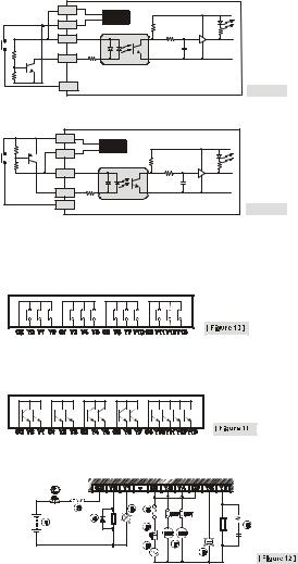
1.DVP-SV has two output modules, relay and transistor. Be aware of the connection of shared terminals when wiring output terminals.
2.Output terminals, Y0, Y1, and Y2, of relay models use C0 common port; Y3, Y4, and Y5 use C1 common port; Y6, Y7, and Y10 use C2 common port; Y11, Y12, and Y13 use C3 common port. See [Figure 10].
When the output points are enabled, their corresponding indicators on the front panel will be on.
3.Output terminals, Y0 and Y1, of transistor models use C0 common port; Y2 and Y3 use C1 common port; Y4 and Y5 use C2 common port; Y6 and Y7 use C3 common port; Y10, Y11, Y12 and Y13 use C4 common port. See [Figure 11].
4.Isolation circuit: The optical coupler is used to isolate signals between the circuit inside PLC and input modules.
Relay (R) output circuit wiring
- 5 -
 Loading...