


DVPEN01-SL
Ethernet Communication Module
Operation Manual
DVP-0204320-02

Ethernet Communication Module DVPEN01-SL
Warning
3Please read this instruction carefully before use and follow this instruction to operate the device in order to prevent damages on the device or injuries to staff.
3Switch off the power before wiring.
3RTU-DNET is an OPEN TYPE device and therefore should be installed in an enclosure free of airborne dust, humidity, electric shock and vibration. The enclosure should prevent non-maintenance staff from operating the device (e.g. key or specific tools are required for operating the enclosure) in case danger and damage on the device may occur.
3RTU-DNET is to be used for controlling the operating machine and equipment. In order not to damage it, only qualified professional staff familiar with the structure and operation of RTU-DNET can install, operate, wire and maintain it.
3DO NOT connect input AC power supply to any of the I/O terminals; otherwise serious damage may occur. Check all the wirings again before switching on the power and DO NOT touch any terminal when the power is switched on. Make sure the ground terminal  is correctly grounded in order to prevent electromagnetic interference.
Table of Contents
1 |
INTRODUCTION................................................................................................................................... |
3 |
|
|
1.1 |
Functions..................................................................................................................................... |
3 |
|
1.2 |
Specifications .............................................................................................................................. |
3 |
2 |
PRODUCT PROFILE & OUTLINE ....................................................................................................... |
4 |
|
|
2.1 |
Dimension ................................................................................................................................... |
4 |
|
2.2 |
Product Profiles........................................................................................................................... |
4 |
|
2.3 |
LED Indicators............................................................................................................................. |
5 |
|
2.4 |
RJ-45 PIN Definition.................................................................................................................... |
5 |
3 |
INSTALLATION & WIRING .................................................................................................................. |
5 |
|
|
3.1 |
Installation ................................................................................................................................... |
5 |
4 |
CONTROL REGISTER (CR) ................................................................................................................ |
6 |
|
|
4.1 |
Control Registers in DVPEN01-SL.............................................................................................. |
6 |
|
4.2 |
Explanations on CR .................................................................................................................... |
8 |
|
4.3 |
Numbering of Left-Side Modules............................................................................................... |
13 |
5 |
SETTING UP SOFTWARE ................................................................................................................. |
14 |
|
|
5.1 |
Setting up Communication & Searching for Modules................................................................ |
14 |
|
5.2 |
Basic Settings ........................................................................................................................... |
20 |
|
5.3 |
Network Settings ....................................................................................................................... |
21 |
|
5.4 |
Setting up E-Mails ..................................................................................................................... |
24 |
|
5.5 |
Data Exchange.......................................................................................................................... |
25 |
|
5.6 |
RTU ........................................................................................................................................... |
26 |
|
5.7 |
IP Filter...................................................................................................................................... |
27 |
|
5.8 |
Static ARP Table........................................................................................................................ |
27 |
|
5.9 |
Setting up Password ................................................................................................................. |
28 |
DVP-PLC Operation Manual |
1 |

Ethernet Communication Module DVPEN01-SL |
|
|
5.10 |
Returning to Default Setting ..................................................................................................... |
29 |
6 APPLICATION EXAMPLES............................................................................................................... |
30 |
|
6.1 |
Setting up IP and Communicating through WPLSoft................................................................ |
30 |
6.2 |
Connecting the PC with DVPEN01-SL through LAN ................................................................ |
33 |
6.3 |
Setting up Password and Clearing Password .......................................................................... |
37 |
6.4 |
When the Password is Lost (Returning to Default Setting by RS-232)..................................... |
39 |
6.5 |
IP Filter Protection .................................................................................................................... |
40 |
6.6 |
Setting up Static ARP Table ...................................................................................................... |
42 |
6.7 |
Application of E-Mail................................................................................................................. |
44 |
6.8 |
Application of Data Exchange (1) ............................................................................................. |
45 |
6.9 |
Application of Data Exchange (2) ............................................................................................. |
48 |
6.10 |
Application of Data Exchange (3) ............................................................................................. |
49 |
6.11 |
Application of Data Exchange (4) ............................................................................................. |
50 |
6.12 |
Application of Data Exchange (5) ............................................................................................. |
52 |
6.13 |
Application of Modbus TCP Master .......................................................................................... |
53 |
6.14 |
RTU Mapping............................................................................................................................ |
54 |
2 |
DVP-PLC Operation Manual |

Ethernet Communication Module DVPEN01-SL
1 Introduction
Thank you for choosing DVPEN01-SL module. To correctly install and operate DVPEN01-SL, please read the manual carefully before using the module.
DVPEN01-SL is an Ethernet communication module for remote setting and communication through WPLSoft. DVPEN01-SL is able to send E-mails, automatically correct the RTC in DVP28SV11R/T and exchange data. It supports Modbus TCP communication protocol and can conduct remote monitoring by using SCADA (Supervisor Control and Data Acquisition) software or HMI (Human Machine Interfaces). DVPEN01-SL can be the master of Modbus TCP, sending out Modbus TCP instructions and controlling the peripheral equipment. In addition, under MDI/MDI-X auto-detection, it does not need to use a crossing cable. See the contents below for more detailed instructions on DVPEN01-SL module.
1.1Functions
zAuto-detects 10/100Mbps transmission speed
zMDI/MDI-X auto-detection
zSupports Modbus TCP protocol (at the same time supports Master and Slave mode)
zAble to send out E-mails
zAuto-corrects the RTC in PLC through the Internet time correction function
zSupports point-to-point data exchange (Max. data exchange length: 200 bytes)
1.2Specifications
Internet interface
Item |
Specification |
|
|
Interface |
RJ-45 with Auto MDI/MDIX |
|
|
Number of ports |
1 Port |
|
|
Transmission method |
IEEE802.3, IEEE802.3u |
|
|
Transmission cable |
Category 5e |
|
|
Transmission speed |
10/100 Mbps Auto-Detect |
|
|
Network protocol |
ICMP, IP, TCP, UDP, DHCP, SMTP, NTP, Modbus TCP |
|
|
Serial communication interface |
|
|
|
Item |
Specification |
|
|
Interface |
RS-232 |
|
|
Number of ports |
1 Port |
|
|
Transmission cable |
DVPACAB230, DVPACAB215, DVPACAB2A30, DVPACAB2B10 |
|
|
Environment |
|
|
Specification |
Item |
|
|
ESD (IEC 61131-2, IEC 61000-4-2): 8KV Air Discharge |
|
|
|
EFT (IEC 61131-2, IEC 61000-4-4): Power Line: 2KV |
Noise immunity |
Analog & Communication I/O: 1KV |
|
Damped-Oscillatory Wave: Power Line: 1KV |
|
RS (IEC 61131-2, IEC 61000-4-3): 26MHz ~ 1GHz, 10V/m |
Environment |
Operation: 0°C ~ 55°C (temperature), 50 ~ 95% (humidity), Pollution degree 2; |
|
|
DVP-PLC Operation Manual |
3 |
Ethernet Communication Module DVPEN01-SL
Item |
Specification |
|
|
|
Storage: -25°C ~ 70°C (temperature), 5 ~ 95% (humidity) |
|
|
Vibration/ Shock Resistance |
Standard: IEC61131-2, IEC 68-2-6 (TEST Fc)/IEC61131-2 & IEC 68-2-27 (TEST Ea) |
|
|
Electrical specifications |
|
|
|
Item |
Specification |
|
|
Power supply voltage |
24VDC (-15% ~ 20%) (Power is supplied by the internal bus of MPU.) |
|
|
Power consumption |
1.5W |
|
|
Insulation voltage |
500V |
|
|
Weight (g) |
92 (g) |
|
|
2Product Profile & Outline
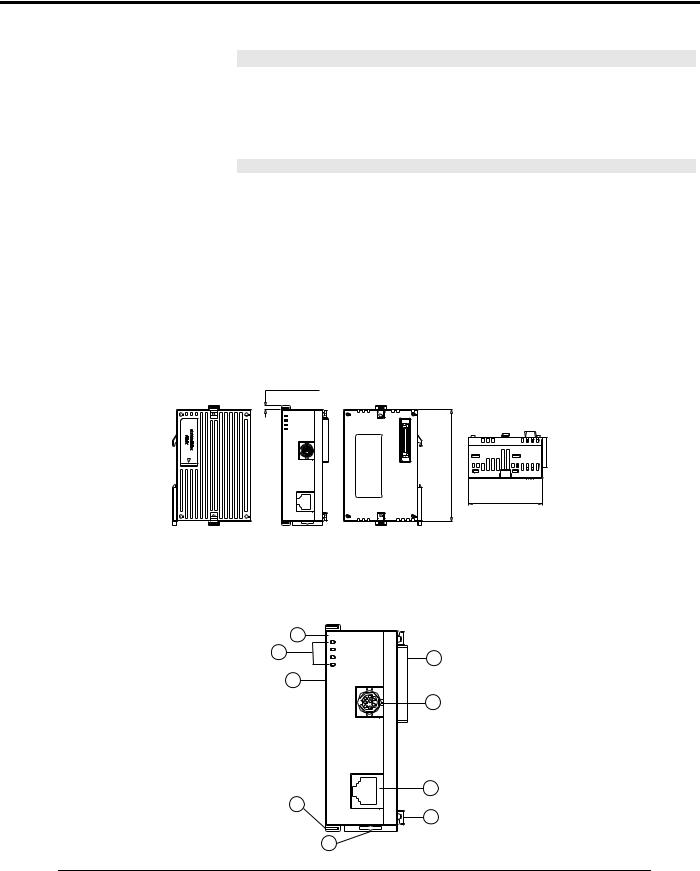
2.1Dimension
3 [0.118]
DVPEN01
POWER
RS-232
100M
LINK
RS-232 [3.543]
90
LAN
Unit: mm [inches]
2.2Product Profiles
1 |
DVPEN01 |
|
POWER |
|
|
4 |
RS-232 |
2 |
100M |
||
|
LINK |
3
8
RS-232
7 |
|
9 |
LAN |
6 |
|
|
||
|
5 |
|
60 [2.362]
|
1. |
Model name |
6. |
Fixing tenon for I/O module |
|
|
2. |
Extension port to connect device |
7. |
Fixing clip for I/O module |
|||
|
|
|
|
|
|
|
3. |
Extension port to connect I/O module |
8. |
RS-232 connection port |
|||
|
|
|
|
|
|
|
4. |
POWER, LINK, RS-232, 100M indicators |
9. |
Ethernet RJ-485 connection port |
|||
|
|
|
|
|
|
|
5. |
DIN rail clip |
|
|
|
||
|
|
|
|
|
|
|
|
|
|
|
|
|
|
|
4 |
|
|
|
DVP-PLC Operation Manual |
|
Ethernet Communication Module DVPEN01-SL
2.3LED Indicators
Indicator |
Color |
Indication |
POWER |
Green |
Power indication |
|
|
|
RS-232 |
Red |
Communication status of the series port |
|
|
|
100M |
Orange |
Network connection status |
|
|
|
LINK |
Green |
Network communication speed |
|
|
|
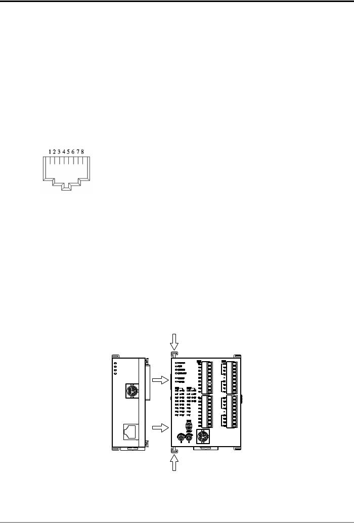
2.4RJ-45 PIN Definition
RJ-45 sketch |
Terminal No. |
Definition |
Explanation |
|
|
|
|
|
1 |
Tx+ |
Positive pole for data transmission |
|
|
|
|
|
2 |
Tx- |
Negative pole for data transmission |
|
|
|
|
|
3 |
Rx+ |
Positive pole for data receiving |
|
|
|
|
|
6 |
Rx- |
Negative pole for data receiving |
|
|
|
|
|
4, 5, 7, 8 |
- |
N/C |
|
|
|
|
3 Installation & Wiring
This section gives instructions on how to connect DVPEN01-SL with PLC MPU and how to connect DVPEN01-SL to the network.
3.1Installation
Connect PLC MPU to DVPEN01-SL
zAdjust the I/O module clip on the left side of the MPU.
zMeet the I/O module port of the MPU with DVPEN01-SL as shown in the figure below.
zFasten the I/O module clip on the left side of the MPU.
DVPEN01 |
DVP28SV |
POWER |
|
RS-232 |
|
100M |
|
LINK |
|
|
RS-232 |
LAN
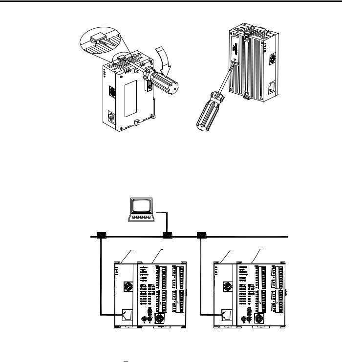
Connect DVPEN01-SL to other I/O modules
zTo connect DVPEN01-SL with the other I/O module, lift the extension clip of the I/O module by a screwdriver and open the side cover.
DVP-PLC Operation Manual |
5 |
Ethernet Communication Module DVPEN01-SL
Connect DVPEN01-SL to the Network:
Connect DVPEN01-SL to the Ethernet Hub by twisted pair cable CAT-5e. DVPEN01-SL has Auto MDI/MDIX function; therefore, DVPEN01-SL does not need to use a crossing cable between the PC and DVPEN01-SL. Network connections between the PC and DVPEN01-SL:
PC Master
|
|
|
Ethernet |
|
DVPEN01 DVP28SV |
|
DVPEN01 DVP28SV |
DVPEN01 |
DVP28SV |
DVPEN01 |
DVP28SV |
POWER |
|
POWER |
|
RS-232 |
|
RS-232 |
|
100M |
|
100M |
|
LINK |
|
LINK |
|
|
RS-232 |
|
RS-232 |
LAN |
LAN |
4Control Register (CR)
4.1Control Registers in DVPEN01-SL
|
|
CR# |
Attribute |
Content |
Explanation |
|
|
|
HW |
LW |
|||
|
|
|
|
|
||
|
|
|
#0 |
R |
Model name |
Set up by the system; read only. Model code of DVPEN01-SL |
|
|
= H’4050 |
||||
|
|
|
|
|
|
|
|
|
|
#1 |
R |
Firmware version |
Displaying the current firmware version in hex. |
|
|
|
|
|
|
|
|
|
|
#2 |
R |
Communication mode |
b0: Modbus TCP mode; b1: data exchange mode |
|
|
|
|
|
|
|
|
|
|
#3 |
W |
E-Mail Event 1 trigger |
Set up whether to send E-Mail 1 |
|
|
|
|
|
|
|
|
|
|
#4 |
W |
E-Mail Event 2 trigger |
Set up whether to send E-Mail 2 |
|
|
|
|
|
|
|
|
|
|
#5 |
W |
E-Mail Event 3 trigger |
Set up whether to send E-Mail 3 |
|
|
|
|
|
|
|
|
|
|
#6 |
W |
E-Mail Event 4 trigger |
Set up whether to send E-Mail 4 |
|
|
|
|
|
|
|
|
|
|
|
|
|
|
|
6 |
|
|
|
|
DVP-PLC Operation Manual |

Ethernet Communication Module DVPEN01-SL
CR# |
Attribute |
Content |
Explanation |
||
HW |
LW |
||||
|
|
|
|||
|
#7 |
R |
Status of E-Mail 1, 2 |
b0 ~ b7: Current status of E-Mail 2 |
|
|
b8 ~ b15: Current status of E-Mail 1 |
||||
|
|
|
|
||
|
#8 |
R |
Status of E-Mail 3, 4 |
b0 ~ b7: Current status of E-Mail 4 |
|
|
b8 ~ b15: Current status of E-Mail 3 |
||||
|
|
|
|
||
|
|
|
|
|
|
|
#9 |
R/W |
E-Mail 1 additional |
Filled in by the user, and it will be send by E-mail. |
|
|
message |
||||
|
|
|
|
||
|
#10 |
R/W |
E-Mail 2 additional |
Filled in by the user, and it will be send by E-mail. |
|
|
message |
||||
|
|
|
|
||
|
#11 |
R/W |
E-Mail 3 additional |
Filled in by the user, and it will be send by E-mail. |
|
|
message |
||||
|
|
|
|
||
|
#12 |
R/W |
E-Mail 4 additional |
Filled in by the user, and it will be send by E-mail. |
|
|
message |
||||
|
|
|
|
||
|
#13 |
R/W |
Data exchange trigger |
Set up whether to send out data in data exchange mode |
|
|
|
|
|
|
|
|
#14 |
R |
Status of data exchange |
Displaying current status of data exchange. |
|
|
|
|
|
|
|
|
#15 |
RW |
Enabling flag for RTU |
1: Enable; 0: Disable. Default = 0 |
|
|
mapping |
||||
|
|
|
|
||
|
|
|
|
b0: Status of RTU slave 1 |
|
|
#16 |
RW |
Connection status of |
b1: Status of RTU slave 2 |
|
|
RTU mapping slave |
b2: Status of RTU slave 3 |
|||
|
|
|
|||
|
|
|
|
b3: Status of RTU slave 4 |
|
|
|
|
|
|
|
#24 ~ #17 |
- |
Reserved |
|
||
|
|
|
|
|
|
#26 |
#25 |
R/W |
Destination IP |
Destination IP address for data exchange |
|
|
|
|
|
|
|
|
#27 |
- |
Reserved |
|
|
|
|
|
|
|
|
|
#28 |
R/W |
Destination Slave ID |
Destination Slave ID for data exchange |
|
|
|
|
|
|
|
#48 ~ #29 |
R/W |
Data transmission buffer |
Buffer for transmitted data in data exchange |
||
|
|
|
|
||
#68 ~ #49 |
R |
Data receiving buffer |
Buffer for received data in data exchange |
||
|
|
|
|
||
#80 ~ #69 |
- |
Reserved |
|
||
|
|
|
|
|
|
|
#81 |
R/W |
Read address for data |
Slave transmission buffer address for data exchange |
|
|
exchange |
||||
|
|
|
|
||
|
#82 |
R/W |
Read length for data |
Number of registers for read data |
|
|
exchange |
||||
|
|
|
|
||
|
#83 |
R/W |
Received address for |
Buffer address for the receiving Master in data exchange |
|
|
data exchange |
||||
|
|
|
|
||
|
#84 |
R/W |
Written-in address for |
Buffer address for the receiving Slave in data exchange |
|
|
data exchange |
||||
|
|
|
|
||
|
#85 |
R/W |
Written-in length for data |
Number of registers for data transmission |
|
|
|
|
exchange |
|
|
|
#86 |
R/W |
Transmission address |
Master transmission buffer address for data exchange |
|
|
for data exchange |
||||
|
|
|
|
||
#110 ~ #87 |
- |
Reserved |
|
||
|
|
|
|
|
|
|
#111 |
R/W |
8-bit processing mode |
Setting up Modbus TCP Master control as 8-bit mode |
|
|
|
|
|
|
|
|
#112 |
R/W |
Modbus TCP Keep-Alive |
Modbus TCP Keep-Alive Time-out (s) |
|
|
|
|
Time-out |
|
|
|
#113 |
- |
Reserved |
|
|
|
|
|
|
|
|
|
#114 |
R/W |
Modbus TCP time-out |
Setting up Modbus TCP time-out (in ms) |
|
|
|
|
|
|
|
DVP-PLC Operation Manual |
7 |

Ethernet Communication Module DVPEN01-SL
|
CR# |
Attribute |
Content |
Explanation |
|
||
|
HW |
LW |
|
||||
|
|
|
|
|
|||
|
|
#115 |
R/W |
Modbus TCP trigger |
Setting up whether to send out data in Modbus TCP mode |
||
|
|
|
|
|
|
||
|
|
#116 |
R/W |
Modbus TCP status |
Displaying current status of Modbus TCP mode |
||
|
|
|
|
|
|
|
|
#118 |
#117 |
R/W |
Modbus TCP |
Setting up destination IP address for Modbus TCP transaction |
|||
destination IP |
|||||||
|
|
|
|
|
|
||
|
|
#119 |
R/W |
Modbus TCP data length |
Setting up the data length for Modbus TCP transaction |
||
|
|
|
|
|
|||
#219 ~ #120 |
R/W |
Modbus TCP data buffer |
Data buffer of Modbus TCP for storing sending/receiving data |
||||
|
|
|
|
|
|||
#248 ~ #220 |
- |
Reserved |
|
|
|||
|
|
|
|
|
|
||
|
|
#251 |
R |
Error code |
Displaying the errors. See table of error codes in the following |
||
|
|
section for more information. |
|||||
|
|
|
|
|
|||
#255 ~ #252 |
- |
Reserved |
|
|
|||
|
|
|
|
|
|
|
|
Symbols “R” refers to “able to read data by FROM instrcution”; “W” refers to “able to write data by TO instrcution”.
4.2Explanations on CR
CR#0: Model Name
Explanations:
1.Model code of DVPEN01-SL = H’4050.
2.You can read the model code in the program to see if the I/O module exists.
CR#1: Firmware Version
Explanations:
The firmware version of DVPEN01-SL is displayed in hex, e.g. H’0100 indicates version V1.00.
CR#2: Communication Mode
Explanations:
Bit No. |
Mode |
“0” |
“1” |
b0 |
Modbus TCP |
Disable |
Enable |
|
|
|
|
b1 |
Data exchange |
Disable |
Enable |
|
|
|
|
E-mail Functions
CR#3 ~ 6: E-Mail Event 1 ~ 4 Trigger
Explanations:
When the CR is set as “1”, E-mail sending will be enabled. After the sending is completed, the CR will automatically be reset as “0”. Note: Please trigger by differential instructions.
8 |
DVP-PLC Operation Manual |
Ethernet Communication Module DVPEN01-SL
CR#7 ~ 8: Status of E-Mail 1 ~ 4
Explanations:
1.CR#7_b0 ~ b7: current status of E-Mail 2; CR#7_b8 ~ b15: current status of E-Mail 1.
2.CR#8_b0 ~ b7: current status of E-Mail 4; CR#8_b8 ~ b15: current status of E-Mail 3.
3.Table of E-Mail status
CR value |
E-Mail status |
0 |
Not been sent |
|
|
1 |
Being processed |
|
|
2 |
E-Mail sending is successful |
|
|
10 |
Fail to connect to SMTP-Server |
|
|
11 |
Incorrect recipient E-Mail address |
|
|
12 |
SMTP-Server communication error |
|
|
13 |
Exceeding the max. number of TCP connection |
|
|
3 ~ 9, 14 ~ 255 |
Reserved |
|
|
CR#9 ~ 12: E-Mail 1 ~ 4 Additional Message
Explanations:
The user fills in the code, and the code will be stored in the title of the E-Mail and sent out with the E-Mail.
Data Exchange
CR#13: Data Exchange Trigger
Explanations:
When the CR is set as “0”, the data in data exchange area will not be transmitted. When the CR is set as “1”, the data in data exchange area will be transmitted.
fWhen the Execute Mode in the software is set to “Program Control” (See 5.5), set CR#13 to 2, and the data exchange will continue to execute. Set CR#13 to 0 to stop the data exchange.
fWhen the Execute Mode in the software is set to “Always Enable”, the data exchange will
continue to execute whatever the setting in CR#13 is.
(Firmware V2.0 and later versions support continuous execution of data exchange.)
CR#14: Data Exchange Status
Explanations:
When the CR is set as “0”, the data have not yet been received. When the CR is set as “1”, the data exchange is in progress. When the CR is set as “2”, the data exchange is successful. When the CR is set as “3”, the data exchange fails.
DVP-PLC Operation Manual |
9 |

Ethernet Communication Module DVPEN01-SL
CR value |
Status |
0 |
Data have not yet been received. |
|
|
1 |
Data exchange is in progress. |
|
|
2 |
Data exchange is successful. |
|
|
3 |
Data exchange fails. |
|
|
CR#25, 26: Destination IP
Explanations:
To set up the Slave IP address for data exchange manually, write “0” into CR#28 first before setting up the destination IP. For example, if the user wants to set the destination IP address to 192.168.0.2, write H’0002 to CR#25 and H’C0A8 to CR#26. (K192 = H’C0, K168 = H’A8, K0 = H’00, K2 = H’02).
CR#28: Destination Slave ID
Explanations:
When you set up the Salve ID (i.e. K1 ~ K255) for data exchange, DVPEN01-SL will automatically search for the corresponding IP address from the Slave IP list. For example, if the ID is set as “0”, the value in CR#25 and #26 will be regarded as the destination IP.
CR#29 ~ 48: Data Transmission Buffer
Explanations:
Storing the data to be transmitted to the remote MPU.
CR#49 ~ 68: Data Receiving Buffer
Explanations:
Storing the data received from the remote MPU.
CR#81: Read Address for Data Exchange
Explanations:
Setting up manually the Modbus address of the register for Slave data exchange. Only register address is allowed (e.g. D0 = H’1000).
CR#82: Read Length for Data Exchange
Explanations:
The number of receiving registers (K1 ~ K100) in data exchange.
10 |
DVP-PLC Operation Manual |

Ethernet Communication Module DVPEN01-SL
CR#83: Read Length for Data Exchange
Explanations:
Setting up the Modbus address of the register for Master data exchange.
CR#84: Written-in Address for Data Exchange
Explanations:
Setting up manually the Modbus address of the register for Slave data exchange.
CR#85: Written-in Address for Data Exchange
Explanations:
The number of transmission registers (K1 ~ K100) in data exchange.
CR#86: Transmission Address for Data Exchange
Explanations:
1.Setting up the Modbus address of the register for Master data exchange.
2.Example: Write H’1000 (D0) into CR#81, K1 into CR#82, and H’1064 (D100) into CR#83. If the data exchange is successful, the value in D0 of the Slave will be written into D100 of the MPU. Or write H’1002 (D2) into CR#84, K4 into CR#85, and H’1008 (D8) into CR#86. If the data exchange is successful, the value in D8 ~ D11 of the Master will be written into D2 ~ D5 of the Slave. Both sending and receiving can be executed at the same time. When the values in CR#82 and #85 are both “0”, DVPEN01-SL will use the default registers (CR#29 ~ CR#68) and number of registers (K20).
Sending Modbus TCP Instruction
CR#111: 8-bit Processing Mode
Explanations:
Setting up the Modbus TCP transmission mode. When the CR value is set as “0” Æ 16-bit mode; when the CR value is set as “1” Æ 8-bit mode.
CR#112: Modbus Client Keep-Alive Time-out
Explanations:
CR#112 is the TCP Keep-Alive time-out for Modbus TCP connection (s). Default: 30s. If the connection idle time becomes longer than the keep-alive time-out, DVPEN01-SL will cut off the idle connection.
DVP-PLC Operation Manual |
11 |

Ethernet Communication Module DVPEN01-SL
CR#114: Modbus TCP Time-Out
Explanations:
Setting up the communication time-out (in ms) for Modbus TCP mode.
CR#115: Modbus TCP Trigger
Explanations:
When the CR value is set as “1”, Modbus TCP will be triggered. After the data transmission is completed in Modbus TCP mode, the CR value will automatically be reset to “0”. Please trigger by differential instructions.
CR#116: Modbus TCP Status
Explanations:
Displaying the current communication status of Modbus TCP mode. When the CR value is set as”0” Æ the data have not yet been received; when the CR value is set as “1” Æ the data exchange is in progress; when the CR value is set as “2” Æ the data exchange is successful; when the CR value is set as “3” Æ the data exchange fails.
CR value |
Data exchange status |
0 |
The data have not been received. |
|
|
1 |
The data exchange is in progress. |
|
|
2 |
The data exchange is successful. |
|
|
3 |
The data exchange fails. |
|
|
CR#117, 118: Modbus TCP Destination IP
Explanations:
Setting up the destination IP address in Modbus TCP mode. See explanations on CR#70 and #71 for how to set.
CR#119: Modbus TCP Data Length
Explanations:
Setting up the length of communication data in Modbus TCP mode. Length for 8-bit mode: K1 ~K100; length for 16-bit mode: K1 ~ K200.
CR#120 ~ 219: Modbus TCP Data Buffer
Explanations:
Buffer for transmitted/received data in Modbus TCP mode.
12 |
DVP-PLC Operation Manual |

Ethernet Communication Module DVPEN01-SL
CR#251: Error Code
Explanations:
Table of error code:
Bit No. |
Error |
|
b0 |
The network is not yet connected. |
|
|
|
|
b1 |
Incorrect IP setting |
|
|
|
|
b2 |
CR#13 is set as “transmitting data”, but the data exchange |
|
is forbidden. |
||
|
||
b3 |
CR#13 is set as “transmitting data”, but the data exchange |
|
mode has not yet been enabled. |
||
|
||
b4 |
NTP-Server connection fails. |
|
|
|
|
b7 |
SMTP-Server connection fails. |
|
|
|
|
b8 |
DHCP has not obtained the correct network parameter. |
|
|
|
RTU Mapping
CR#15: Enabling Flag for RTU Mapping
Explanations:
1: Enable; 0: Disable. Default = 0
Firmware V2.0 and later versions support RTU mapping.
CR#16: Connection Status of RTU Mapping Slave
Explanations:
b3 ~ b0 display the connection status of RTU slave. The connection may encounter some problems when any of the bits becomes 0. Firmware V2.0 and later versions support RTU mapping.
b0: Status of RTU slave 1 b1: Status of RTU slave 2 b2: Status of RTU slave 3 b3: Status of RTU slave 4
4.3Numbering of Left-Side Modules
After DVPEN01-SL is installed properly, you need to compile the PLC program to control the special I/O module. PLC offers FROM instruction (for reading) and TO instruction (for writing) to control the control registers (CR) in the special I/O module.
Numbering of the modules: Every special I/O module connected to PLC MPU has a No. to allow you to know which module is which when compiling the PLC program. The first special I/O module attached at the left hand side of the PLC MPU is numbered as K100, the second as K101, the third K102, and so on.
DVP-PLC Operation Manual |
13 |
Ethernet Communication Module DVPEN01-SL
5 Setting up Software
This section gives instructions on how to set up DVPEN01-SL by DCISoft and explanations on each setup page. Before you start a setup page, you have to select “Ethernet” in the communication setting. Next, you can search by IP address or use Auto-Search. You also can open the setup page for DVPEN01-SL by RS-232.
DVPEN01-SL is set up by UDP port 20006; therefore, you have to be aware of the relevant settings of the firewall.
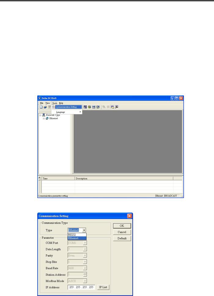
5.1Setting up Communication & Searching for Modules
Communication settings
1.Open DCISoft in your PC and click on “Communication Setting”.
2. Select “Ethernet” as the transmission type.
14 |
DVP-PLC Operation Manual |

Ethernet Communication Module DVPEN01-SL
Broadcast search
1.Click broadcast icon in DCISoft to search for all Delta Ethernet products on the network. The window on the left hand side shows the models found, and the window on the right hand side displays the device list of all models.
2.Click a model on the left hand side, and you will see the device list of the model selected on the right hand side. Click the device to be set up to enter the setup page.
DVP-PLC Operation Manual |
15 |
Ethernet Communication Module DVPEN01-SL
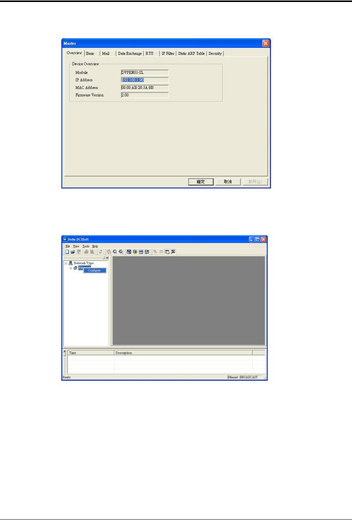
3. You will see the basic setup page as follow.
Designating model to search
1.Right click “Ethernet” on the left hand side window and select “Configure” to designate a model to search for.
16 |
DVP-PLC Operation Manual |
 Loading...