


36-560
INSTRUCTION MANUAL
10" Table Saw
(Model 36-550)
(Model 36-560 w/stand)
PART NO. 904817 - 02-19-02
Copyright © 2002 Delta Machinery
ESPAÑOL: PÁGINA 25
To learn more about DELTA MACHINERY
visit our website at: www.deltamachinery.com.
For Parts, Service, Warranty or other Assistance,
please call
1-800-223-7278 (In Canada call 1-800-463-3582).
Model 36-560 with stand
shown

2
GENERAL SAFETY RULES
Woodworking can be dangerous if safe and proper operating procedures are not followed. As with all machinery, there
are certain hazards involved with the operation of the product. Using the machine with respect and caution will
considerably lessen the possibility of personal injury. However, if normal safety precautions are overlooked or ignored,
personal injury to the operator may result. Safety equipment such as guards, push sticks, hold-downs, featherboards,
goggles, dust masks and hearing protection can reduce your potential for injury. But even the best guard won’t make
up for poor judgment, carelessness or inattention. Always use common sense
and exercise caution
in the workshop.
If a procedure feels dangerous, don’t try it. Figure out an alternative procedure that feels safer. REMEMBER: Your
personal safety is your responsibility.
This machine was designed for certain applications only. Delta Machinery strongly recommends that this machine not
be modified and/or used for any application other than that for which it was designed. If you have any questions relative
to a particular application, DO NOT use the machine until you have first contacted Delta to determine if it can or should
be performed on the product.
Technical Service Manager
Delta Machinery
4825 Highway 45 North
Jackson, TN 38305
(IN CANADA: 505 SOUTHGATE DRIVE, GUELPH, ONTARIO N1H 6M7)
WARNING: FAILURE TO FOLLOW THESE RULES MAY RESULT IN SERIOUS PERSONAL INJURY
1. FOR YOUR OWN SAFETY, READ INSTRUCTION
MANUAL BEFORE OPERATING THE TOOL. Learn the
tool’s application and limitations as well as the specific
hazards peculiar to it.
2. KEEP GUARDS IN PLACE and in working order.
3. ALWAYS WEAR EYE PROTECTION.
Wear safety
glasses. Everyday eyeglasses only have impact resistant
lenses; they are not safety glasses. Also use face or dust
mask if cutting operation is dusty. These safety glasses
must conform to ANSI Z87.1 requirements. NOTE:
Approved glasses have Z87 printed or stamped on them.
4. REMOVE ADJUSTING KEYS AND WRENCHES. Form
habit of checking to see that keys and adjusting wrenches
are removed from tool before turning it “on”.
5. KEEP WORK AREA CLEAN. Cluttered areas and
benches invite accidents.
6. DON’T USE IN DANGEROUS ENVIRONMENT. Don’t
use power tools in damp or wet locations, or expose them
to rain. Keep work area well-lighted.
7. KEEP CHILDREN AND VISITORS AWAY. All children
and visitors should be kept a safe distance from work area.
8. MAKE WORKSHOP CHILDPROOF – with padlocks,
master switches, or by removing starter keys.
9. DON’T FORCE TOOL. It will do the job better and be
safer at the rate for which it was designed.
10. USE RIGHT TOOL. Don’t force tool or attachment to
do a job for which it was not designed.
11. WEAR PROPER APPAREL. No loose clothing, gloves,
neckties, rings, bracelets, or other jewelry to get caught in
moving parts. Nonslip footwear is recommended. Wear
protective hair covering to contain long hair.
12. SECURE WORK. Use clamps or a vise to hold work
when practical. It’s safer than using your hand and frees
both hands to operate tool.
13. DON’T OVERREACH. Keep proper footing and
balance at all times.
14. MAINTAIN TOOLS IN TOP CONDITION. Keep tools
sharp and clean for best and safest performance. Follow
instructions for lubricating and changing accessories.
15. DISCONNECT TOOLS before servicing and when
changing accessories such as blades, bits, cutters, etc.
16. USE RECOMMENDED ACCESSORIES. The use of
accessories and attachments not recommended by Delta
may cause hazards or risk of injury to persons.
17. REDUCE THE RISK OF UNINTENTIONAL STARTING.
Make sure switch is in “OFF” position before plugging in
power cord.
In the event of a power failure, move switch
to the “OFF” position.
18. NEVER STAND ON TOOL. Serious injury could occur if
the tool is tipped or if the cutting tool is accidentally
contacted.
19. CHECK DAMAGED PARTS. Before further use of the
tool, a guard or other part that is damaged should be
carefully checked to ensure that it will operate properly and
perform its intended function – check for alignment of
moving parts, binding of moving parts, breakage of parts,
mounting, and any other conditions that may affect its
operation. A guard or other part that is damaged should be
properly repaired or replaced.
20. DIRECTION OF FEED. Feed work into a blade or
cutter against the direction of rotation of the blade or cutter
only.
21. NEVER LEAVE TOOL RUNNING UNATTENDED.
TURN POWER OFF. Don’t leave tool until it comes to a
complete stop.
22.
STAY ALERT, WATCH WHAT YOU ARE DOING, AND
USE COMMON SENSE WHEN OPERATING A POWER
TOOL. DO NOT USE TOOL WHILE TIRED OR UNDER
THE INFLUENCE OF DRUGS, ALCOHOL, OR
MEDICATION. A moment of inattention while operating
power tools may result in serious personal injury.
23. MAKE SURE TOOL IS DISCONNECTED FROM
POWER SUPPLY while motor is being mounted,
connected or reconnected.
24. THE DUST GENERATED by certain woods and wood
products can be injurious to your health. Always operate
machinery in well ventilated areas and provide for proper
dust removal. Use wood dust collection systems whenever
possible.
25.
WARNING: SOME DUST CREATED BY
POWER SANDING, SAWING, GRINDING, DRILLING,
AND OTHER CONSTRUCTION ACTIVITIES contains
chemicals known to cause cancer, birth defects or other
reproductive harm. Some examples of these chemicals
are:
· lead from lead-based paints,
· crystalline silica from bricks and cement and other
masonry products, and
· arsenic and chromium from chemically-treated lumber.
Your risk from these exposures varies, depending on how
often you do this type of work. To reduce your exposure
to these chemicals: work in a well ventilated area, and
work with approved safety equipment, such as those
dust masks that are specially designed to filter out
microscopic particles.
SAVE THESE INSTRUCTIONS.
Refer to them often and use them to instruct others.

ADDITIONAL SAFETY RULES FOR
TABLE SAW
3
WARNING: FAILURE TO FOLLOW THESE RULES MAY RESULT IN SERIOUS PERSONAL INJURY.
1. DO NOT OPERATE THIS MACHINE until it is
assembled and installed according to the
instructions.
2. OBTAIN ADVICE FROM YOUR SUPERVISOR,
instructor, or another qualified person if you are
not familiar with the operation of this machine.
3. FOLLOW ALL WIRING CODES and recommended
electrical connections.
4. USE THE GUARDS WHENEVER POSSIBLE.
Check to see that they are in place, secured, and
working correctly.
5. AVOID KICKBACK by:
A. keeping blade sharp and free of rust and pitch.
B. keeping rip fence parallel to the saw blade.
C. using saw blade guard and spreader for every
possible operation, including all through
sawing.
D. pushing the workpiece past the saw blade prior
to release.
E. never ripping a workpiece that is twisted or
warped, or does not have a straight edge to
guide along the fence.
F. using feather boards when the anti-kickback
device cannot be used.
G. never sawing a large workpiece that cannot be
controlled.
H. never using the fence as a guide when
crosscutting.
I. never sawing a workpiece with loose knots or
other flaws.
6. ALWAYS USE GUARDS, SPLITTER, AND ANTI-
KICKBACK FINGERS except when otherwise
directed in the manual.
7. REMOVE CUT-OFF PIECES AND SCRAPS from
the table before starting the saw. The vibration of the
machine may cause them to move into the saw
blade and be thrown out. After cutting, turn the
machine off. When the blade has come to a
complete stop, remove all debris.
8. NEVER START THE MACHINE with the workpiece
against the blade.
9. HOLD THE WORKPIECE FIRMLY against the miter
gauge or fence.
10. NEVER run the workpiece between the fence and a
moulding cutterhead.
11. NEVER perform “free-hand” operations. Use either
the fence or miter gauge to position and guide the
workpiece.
12. USE PUSH STICK(S) for ripping a narrow
workpiece.
13. AVOID AWKWARD OPERATIONS AND HAND
POSITIONS where a sudden slip could cause a
hand to move into the blade.
14. KEEP ARMS, HANDS, AND FINGERS away from
the blade.
15. NEVER have any part of your body in line with the
path of the saw blade.
16. NEVER REACH AROUND or over the saw blade.
17. NEVER attempt to free a stalled saw blade without
first turning the machine “OFF”.
18. PROPERLY SUPPORT LONG OR WIDE
workpieces.
19. NEVER PERFORM LAYOUT, assembly or set-up
work on the table/work area when the machine is
running.
20. TURN THE MACHINE “OFF” AND DISCONNECT
THE MACHINE from the power source before
installing or removing accessories, before adjusting
or changing set-ups, or when making repairs.
21. TURN THE MACHINE “OFF”, disconnect the
machine from the power source, and clean the
table/work area before leaving the machine. LOCK
THE SWITCH IN THE “OFF” POSITION to prevent
unauthorized use.
22. ADDITIONAL INFORMATION regarding the safe
and proper operation of this tool is available from
the Power Tool Institute, 1300 Summer Avenue,
Cleveland, OH 44115-2851. Information is also
available from the National Safety Council, 1121
Spring Lake Drive, Itasca, IL 60143-3201. Please
refer to the American National Standards Institute
ANSI 01.1 Safety Requirements for Woodworking
Machines and the U.S. Department of Labor OSHA
1910.213 Regulations.
SAVE THESE INSTRUCTIONS.
Refer to them often
and use them to instruct others.
4
POWER CONNECTIONS
A separate electrical circuit should be used for your machines. This circuit should not be less than #12 wire and should
be protected with a 20 Amp time lag fuse. If an extension cord is used, use only 3-wire extension cords which have 3-
prong grounding type plugs and matching receptacle which will accept the machine’s plug. Before connecting the
motor to the power line, make sure the switch is in the “OFF” position and be sure that the electric current is of the
same characteristics as indicated on the machine. All line connections should make good contact. Running on low
voltage will damage the motor.
WARNING: DO NOT EXPOSE THE MACHINE TO RAIN OR OPERATE THE MACHINE IN DAMP LOCATIONS.
MOTOR SPECIFICATIONS
Your machine is wired for 120 volt, 60 HZ alternating current. Before connecting the machine to the power source,
make sure the switch is in the “OFF” position.
GROUNDING INSTRUCTIONS
WARNING: THIS MACHINE MUST BE GROUNDED WHILE IN USE TO PROTECT THE OPERATOR FROM
ELECTRIC SHOCK.
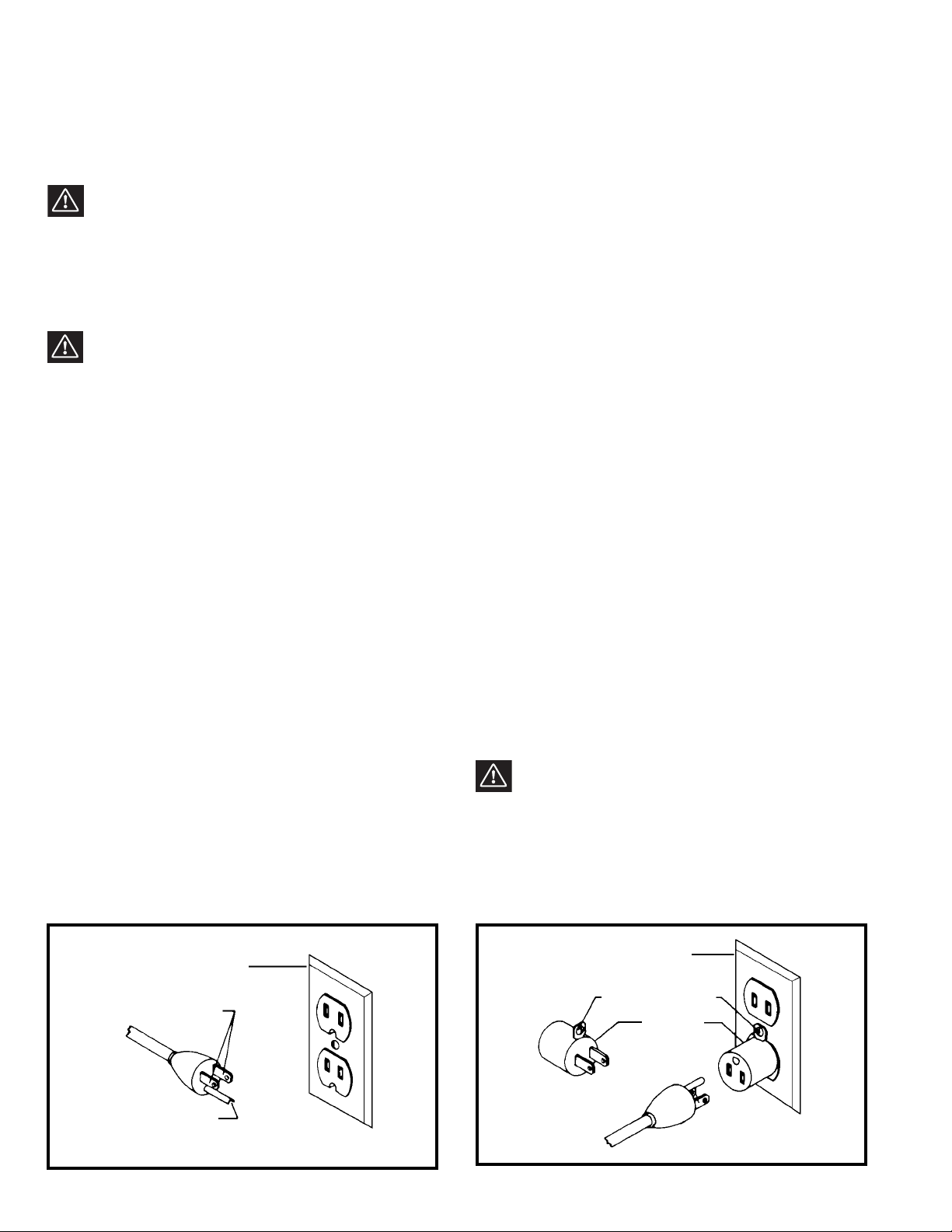
Fig. A Fig. B
GROUNDED OUTLET BOX
CURRENT
CARRYING
PRONGS
GROUNDING BLADE
IS LONGEST OF THE 3 BLADES
GROUNDED OUTLET BOX
GROUNDING
MEANS
ADAPTER
2. Grounded, cord-connected machines intended for use
on a supply circuit having a nominal rating less than 150
volts:
If the machine is intended for use on a circuit that has an
outlet that looks like the one illustrated in Fig. A, the
machine will have a grounding plug that looks like the plug
illustrated in Fig. A. A temporary adapter, which looks like
the adapter illustrated in Fig. B, may be used to connect
this plug to a matching 2-conductor receptacle as shown
in Fig. B if a properly grounded outlet is not available. The
temporary adapter should be used only until a properly
grounded outlet can be installed by a qualified electrician.
The green-colored rigid ear, lug, and the like, extending
from the adapter must be connected to a permanent
ground such as a properly grounded outlet box. Whenever
the adapter is used, it must be held in place with a metal
screw.
NOTE: In Canada, the use of a temporary adapter is not
permitted by the Canadian Electric Code.
WARNING: IN ALL CASES, MAKE CERTAIN THE
RECEPTACLE IN QUESTION IS PROPERLY
GROUNDED. IF YOU ARE NOT SURE HAVE A
QUALIFIED ELECTRICIAN CHECK THE RECEPTACLE.
1. All grounded, cord-connected machines:
In the event of a malfunction or breakdown, grounding
provides a path of least resistance for electric current to
reduce the risk of electric shock. This machine is
equipped with an electric cord having an equipment-
grounding conductor and a grounding plug. The plug must
be plugged into a matching outlet that is properly installed
and grounded in accordance with all local codes and
ordinances.
Do not modify the plug provided - if it will not fit the outlet,
have the proper outlet installed by a qualified electrician.
Improper connection of the equipment-grounding
conductor can result in risk of electric shock. The
conductor with insulation having an outer surface that is
green with or without yellow stripes is the equipment-
grounding conductor. If repair or replacement of the
electric cord or plug is necessary, do not connect the
equipment-grounding conductor to a live terminal.
Check with a qualified electrician or service personnel if
the grounding instructions are not completely
understood, or if in doubt as to whether the machine is
properly grounded.
Use only 3-wire extension cords that have 3-prong
grounding type plugs and matching 3-conductor
receptacles that accept the machine’s plug, as shown in
Fig. A.
Repair or replace damaged or worn cord immediately.
Use proper extension cords. Make sure your extension cord is in good condition and is a 3-wire extension cord which
has a 3-prong grounding type plug and matching receptacle which will accept the machine’s plug. When using an
extension cord, be sure to use one heavy enough to carry the current of the machine. An undersized cord will cause
a drop in line voltage, resulting in loss of power and overheating. Fig. D, shows the correct gauge to use depending
on the cord length. If in doubt, use the next heavier gauge. The smaller the gauge number, the heavier the cord.
EXTENSION CORDS
OPERATING INSTRUCTIONS
FOREWORD
Delta Models 36-560 & 36-550 are table saws that have a “Big saw capacity” at an economical price. The Delta
Models 36-560 & 36-550 have an extra large, 17½"x34" solid anodized aluminum table. The Delta Models 36-560 &
36-550 are powered by a heavy-duty 15 amp. motor with a floating jackshaft gear, which is the most powerful in its
class.
UNPACKING AND CLEANING
Carefully unpack the machine and all loose items from the shipping container(s). Remove the protective coating from
all unpainted surfaces. This coating may be removed with a soft cloth moistened with kerosene (do not use acetone,
gasoline or lacquer thinner for this purpose). After cleaning, cover the unpainted surfaces with a good quality household
floor paste wax.
5
Fig. D
MINIMUM GAUGE EXTENSION CORD
RECOMMENDED SIZES FOR USE WITH STATIONARY ELECTRIC MACHINES
Ampere Total Length Gauge of
Rating Volts of Cord in Feet Extension Cord
0-6 115
up to
25 18 AWG
0-6 115 25-50 16 AWG
0-6 115 50-100 16 AWG
0-6 115 100-150 14 AWG
6-10 115
up to
25 18 AWG
6-10 115 25-50 16 AWG
6-10 115 50-100 14 AWG
6-10 115 100-150 12 AWG
10-12 115
up to
25 16 AWG
10-12 115 25-50 16 AWG
10-12 115 50-100 14 AWG
10-12 115 100-150 12 AWG
12-16 115
up to
25 14 AWG
12-16 115 25-50 12 AWG
12-16 115
GREATER THAN 50 FEET NOT RECOMMENDED
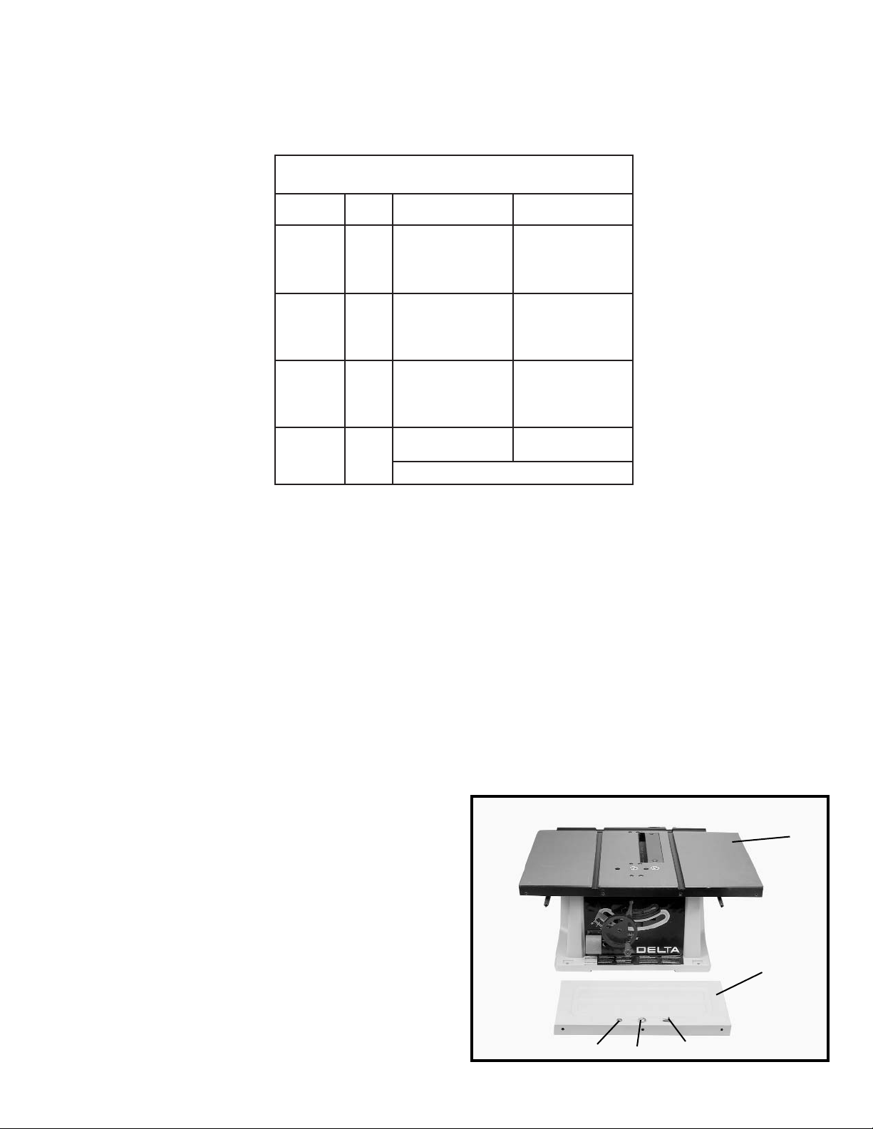
Fig. 2
TABLE SAW PARTS
1
2
3
4 5
1- Saw
2- Extension Wing
3- 1/4”- Flat Washer for Mounting Extension Wing (3)
4- 1/4”- Lockwasher for Mounting Extension Wing (3)
5- 1/4-20 x 5/8” Hex Head Screw for Mounting
Extension Wing (3)
6
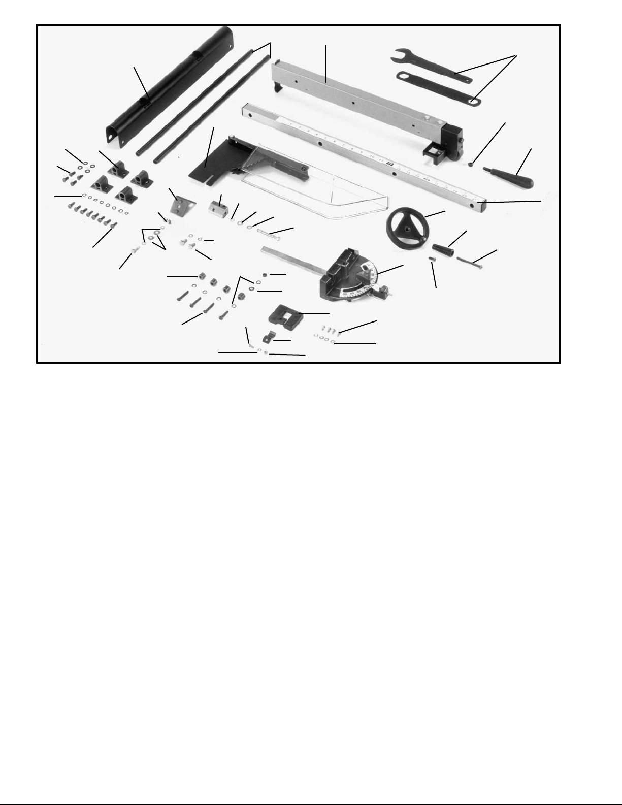
Fig. 3
6 - Rip Fence
7 - Wrenches for Blade Changing
8 - M8 Hex Nut for Rip Fence
9 - Locking Handle for Rip Fence
10 - Fence Rail
11 - Blade Raising and Lowering Handwheel
12 - M6 x 12mm Flat Head Screw for Mounting Blade
Raising and Lowering Handwheel
13 - Handle for Blade Raising and Lowering
Handwheel
14 - M6 x 55mm Cheese Head Screw for Mounting
Handwheel Handle
15 - Miter Gage
16 - M4.2 x10mm Pan Head Screws for Mounting
miter Gage Holder (4)
17 - 3/16" Flat Washers for Mounting Miter Gage
Holder (4)
18 - Miter Gage Holder
19 - Spring Clip for Miter Gage Holder
20 - M4 Hex Nut for Miter Gage Holder
21 - 3/16" External Tooth Lockwasher for Miter Gage
Holder
22 - M4 x 10mm Pan Head Screw for Miter Gage
Holder
23 - 1/4-20 Hex Nut for Mounting Fence Rail to
Extension Wing
24 - 1/4" Lockwashers for Mounting Fence Rail (5)
25 - 1/4" Flat Washer for Mounting Fence Rail to
Extension Wing
26 - 1/4-20 x 1-1/4" Round Head Screws for Mounting
Fence Rail (4)
27 - Spacer for Mounting Fence Rail (4)
28 - 1/4-20 x 2-1/4" Long Hex Head Screw for
Mounting Splitter Bracket
29 - 1/4" Internal Tooth Lockwasher for Mounting
Splitter Bracket
30 - 1/4" Flat Washer for Mounting Splitter Bracket
31 - 1/4" External Tooth Lockwasher for Mounting
Splitter Bracket
32 - Splitter Bracket
33 - 1/4-20 x 1/2" Hex Head Screws for Splitter
Bracket (2)
34 - 1/4" External Tooth Lockwashers for Splitter
Bracket (2)
36 - M6 x 20mm Hex Head Screw for Mounting
Splitter Support Bracket
37 - 1/4" External Tooth Washers for Mounting Splitter
Support Bracket (2)
38 - 1/4" Flat Washers for Mounting Splitter Support
Bracket (2)
39 - Wing Nut for Mounting Splitter Support Bracket
40 - Splitter Support Bracket
41 - Splitter and Guard Assembly
42 - M6 x 15mm Hex Head Screw for Mounting
Outfeed Support Brackets (8)
43 - Flat Washer for Mounting Outfeed Support
Brackets (8)
44 - Outfeed Support Bracket (4)
45 - 1/4-20x1/2" Hex Head Screw for Mounting Rear
Support onto Support Rods (4)
46 - 1/4" Flat Washer for Mounting Rear Support onto
Support Rods (4)
47 - Rear Support
48 - Support Rod (2)
6
7
8
9
10
11
12
13
14
15
16
17
18
19
20
21
22
23
24
25
26
27
33
34
28
29
30
31
32
38
36
37
39
40
41
42
43
45
46
44
47
48
7
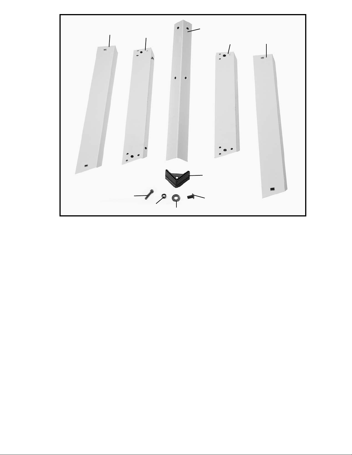
Fig. 4
FOR MODEL 36-560 ONLY
49 - Leg (4)
50 - 3/8” Flat Washer for Mounting Saw to Stand & for Assembling Stand (24)
51 - Foot (4)
52 - M8 Hex Nut for Mounting Saw to Stand & for Assembling Stand (20)
53 - M8 x 40mm Hex Screw for Mounting Saw to Stand (4)
54 - M8 x 20mm Carriage Bolts for Assembling Stand (16)
55 - 18-1/2” Top Front and Rear Brackets (2)
56 - 17” Top Side Brackets (2)
57 - 22” Bottom Front and Rear Brackets (2)
58 - 20-3/8” Bottom Side Brackets (2)
49
56
57
55
58
51
54
50
52
53
8
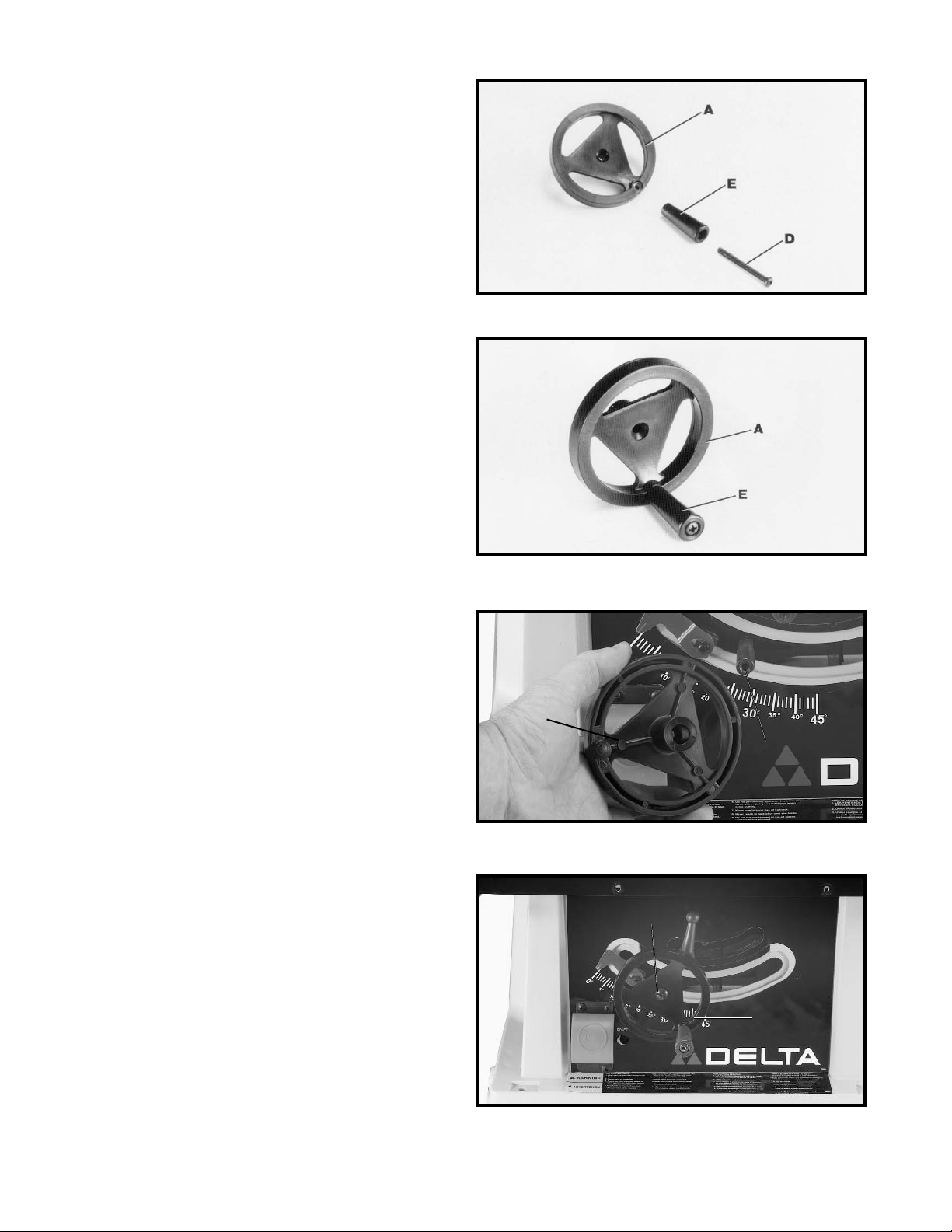
ASSEMBLY
ASSEMBLING BLADE
RAISING AND LOWERING
HANDWHEEL
1. Insert M6 x 55mm cheese head screw (14) Fig. 3,
through handle (E) Fig. 5 and assemble handle (E) to
handwheel (A) by threading screw (D) Fig. 5 clockwise
into handwheel.
2. Fig. 6, illustrates the handle (E) assembled to
handwheel (A).
3. Assemble handwheel (A) Fig. 7, to shaft (B) making
sure the flat on inside of handwheel lines up with flat on
shaft.
4. Fasten handwheel (A) Fig. 8, to shaft (B) Fig. 7, using
a M6 x 12mm flat head screw (C) Fig. 8.
Fig. 5
Fig. 6
Fig. 7
Fig. 8
A
B
A
C
 Loading...