


14-651
Hollow Chisel
Mortiser
Mortaiseuse
à bédane creux
Mortajadora de cincel hueco
Instruction Manual
Manuel d’utilisation
Manual de instrucciones
FRANÇAIS (15) |
ESPAÑOL (27) |
|
|
www.deltamachinery.com
(800) 223-7278 - US
(800) 463-3582 - CANADA
A19592 - 09-15-06
Copyright © 2006 Delta Machinery
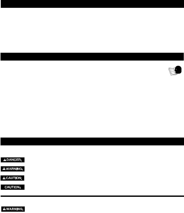
TABLE OF CONTENTS
IMPORTANT SAFETY INSTRUCTIONS .................... |
2 |
TROUBLESHOOTING ................................................ |
12 |
SAFETY GUIDELINES - DEFINITIONS ..................... |
3 |
MAINTENANCE.......................................................... |
12 |
GENERAL SAFETY RULES ....................................... |
3 |
SERVICE..................................................................... |
13 |
ADDITIONAL SPECOFOC SAFETY RULES ............. |
4 |
ACCESSORIES........................................................... |
13 |
FUNCTIONAL DESCRIPTION ................................... |
6 |
WARRANTY................................................................ |
14 |
CARTON CONTENTS ............................................... |
6 |
FRANÇAIS .................................................................. |
15 |
ASSEMBLY ................................................................. |
7 |
ESPAÑOL.................................................................... |
27 |
OPERATION ............................................................... |
10 |
|
|
IMPORTANT SAFETY INSTRUCTIONS
 Read and understand all warnings and operating instructions before using any tool or equipment. When using tools or equipment, basic safety precautions should always be followed to reduce the risk of personal injury. Improper operation, maintenance or modification of tools or equipment could result in serious injury and property damage. There are certain applications for which
tools and equipment are designed. Delta Machinery strongly recommends that this product NOT be modified and/or used for any application other than for which it was designed.
If you have any questions relative to its application DO NOT use the product until you have written Delta Machinery and we have advised you. Contact us online at www.deltamachinery.com or by mail at Technical Service Manager, Delta Machinery, 4825 Highway 45 North, Jackson, TN 38305. In Canada,125 Mural St. Suite 300, Richmond Hill, ON, L4B 1M4)
Information regarding the safe and proper operation of this tool is available from the following sources:
•Power Tool Institute, 1300 Sumner Avenue, Cleveland, OH 44115-2851or online at www.powertoolinstitute.org
•National Safety Council, 1121 Spring Lake Drive, Itasca, IL 60143-3201
•American National Standards Institute, 25 West 43rd Street, 4 floor, New York, NY 10036 www.ansi.org - ANSI 01.1 Safety Requirements for Woodworking Machines
•U.S. Department of Labor regulations www.osha.gov
SAVE THESE INSTRUCTIONS!
SAFETY GUIDELINES - DEFINITIONS
It is important for you to read and understand this manual. The information it contains relates to protecting YOUR SAFETY and PREVENTING PROBLEMS. The symbols below are used to help you recognize this information.
Indicates an imminently hazardous situation which, if not avoided, will result in death or serious injury.
Indicates a potentially hazardous situation which, if not avoided, could result in death or serious injury.
Indicates a potentially hazardous situation which, if not avoided, may result in minor or moderate injury.
Used without the safety alert symbol indicates a potentially hazardous situation which, if not avoided, may result in property damage.
CALIFORNIA PROPOSITION 65
Some dust created by power sanding, sawing, grinding, drilling, and other construction activities contains chemicals known to cause cancer, birth defects or other reproductive harm. Some
examples of these chemicals are:
•lead from lead-based paints,
•crystalline silica from bricks and cement and other masonry products, and
•arsenic and chromium from chemically-treated lumber.
Your risk from these exposures varies, depending on how often you do this type of work. To reduce your exposure to these chemicals: work in a well ventilated area, and work with approved safety equipment, always wear NIOSH/OSHA approved, properly fitting face mask or respirator when using such tools.
2 - English

GENERAL SAFETY RULES
Failure to follow these rules may result in serious personal injury.
1.FOR YOUR OWN SAFETY, READ THE INSTRUCTION MANUAL BEFORE OPERATING THE MACHINE. Learning the machine’s application, limitations, and specific hazards will greatly minimize the possibility of accidents and injury.
2.WEAR EYE AND HEARING PROTECTION. ALWAYS USE SAFETY GLASSES. Everyday eyeglasses are NOT safety glasses. USE CERTIFIED SAFETY EQUIPMENT. Eye protection equipment should comply with ANSI Z87.1 standards. Hearing equipment should comply with ANSI S3.19 standards.
3.WEAR PROPER APPAREL. Do not wear loose clothing, gloves, neckties, rings, bracelets, or other jewelry which may get caught in moving parts. Nonslip protective footwear is recommended. Wear protective hair covering to contain long hair.
4.DO NOT USE THE MACHINE IN A DANGEROUS ENVIRONMENT. The use of power tools in damp or wet locations or in rain can cause shock or electrocution. Keep your work area well-lit to prevent tripping or placing arms, hands, and fingers in danger.
5.MAINTAIN ALL TOOLS AND MACHINES IN PEAK CONDITION. Keep tools sharp and clean for best and safest performance. Follow instructions for lubricating and changing accessories. Poorly maintained tools and machines can further damage the tool or machine and/or cause injury.
6.CHECK FOR DAMAGED PARTS. Before using the machine, check for any damaged parts. Check for alignment of moving parts, binding of moving parts, breakage of parts, and any other conditions that may affect its operation. A guard or any other part that is damaged should be properly repaired or replaced with Delta or factory authorized replacement parts. Damaged parts can cause further damage to the machine and/or injury.
7.KEEP THE WORK AREA CLEAN. Cluttered areas and benches invite accidents.
8.KEEP CHILDREN AND VISITORS AWAY. Your shop is a potentially dangerous environment. Children and visitors can be injured.
9.REDUCE THE RISK OF UNINTENTIONAL STARTING. Make sure that the switch is in the “OFF” position before plugging in the power cord. In the event of a power failure, move the switch to the “OFF” position. An accidental start-up can cause injury. Do not touch the plug’s metal prongs when unplugging or plugging in the cord.
10.USE THE GUARDS. Check to see that all guards are in place, secured, and working correctly to prevent injury.
11.REMOVE ADJUSTING KEYS AND WRENCHES BEFORE STARTING THE MACHINE. Tools, scrap pieces, and other debris can be thrown at high speed, causing injury.
12.USE THE RIGHT MACHINE. Don’t force a machine or an attachment to do a job for which it was not designed. Damage to the machine and/or injury may result.
13.USE RECOMMENDED ACCESSORIES. The use of accessories and attachments not recommended by Delta may cause damage to the machine or injury to the user.
14.USE THE PROPER EXTENSION CORD. Make sure your extension cord is in good condition. When using an extension cord, be sure to use one heavy enough to carry the current your product will draw. An undersized cord will cause a drop in line voltage, resulting in loss of power and overheating. See the Extension Cord Chart for the correct size depending on the cord length and nameplate ampere rating. If in doubt, use the next heavier gauge. The smaller the gauge number, the heavier the cord.
15.SECURE THE WORKPIECE. Use clamps or a vise to hold the workpiece when practical. Loss of control of a workpiece can cause injury.
16.FEED THE WORKPIECE AGAINST THE DIRECTION OF THE ROTATION OF THE BLADE, CUTTER, OR ABRASIVE SURFACE. Feeding it from the other direction will cause the workpiece to be thrown out at high speed.
17.DON’T FORCE THE WORKPIECE ON THE MACHINE.
Damage to the machine and/or injury may result.
18.DON’T OVERREACH. Loss of balance can make you fall into a working machine, causing injury.
19.NEVER STAND ON THE MACHINE. Injury could occur if the tool tips, or if you accidentally contact the cutting tool.
20.NEVER LEAVE THE MACHINE RUNNING UNATTENDED. TURN THE POWER OFF. Don’t leave the machine until it comes to a complete stop. A child or visitor could be injured.
21.TURN THE MACHINE “OFF”, AND DISCONNECT THE MACHINE FROM THE POWER SOURCE before installing or removing accessories, changing cutters, adjusting or changing set-ups. When making repairs, be sure to lock the start switch in the “OFF” position. An accidental start-up can cause injury.
22.MAKE YOUR WORKSHOP CHILDPROOF WITH PADLOCKS, MASTER SWITCHES, OR BY REMOVING STARTER KEYS. The accidental start-up of a machine by a child or visitor could cause injury.
23. STAY ALERT, WATCH WHAT YOU ARE DOING, AND USE
COMMON SENSE. DO NOT USE THE MACHINE WHEN YOU ARE TIRED OR UNDER THE INFLUENCE OF DRUGS, ALCOHOL, OR MEDICATION. A moment of inattention while operating power tools may result in injury.
24.  USE OF THIS TOOL CAN GENERATE
AND DISBURSE DUST OR OTHER AIRBORNE PARTICLES, INCLUDING WOOD DUST, CRYSTALLINE SILICA DUST AND ASBESTOS DUST. Direct particles away from face and body. Always operate tool in well ventilated area and provide for proper dust removal. Use dust collection system wherever possible. Exposure to the dust may cause serious and permanent respiratory or other injury, including silicosis (a serious lung disease), cancer, and death. Avoid breathing the dust, and avoid prolonged contact with dust. Allowing dust to get into your mouth or eyes, or lay on your skin may promote absorption of harmful material. Always use properly fitting NIOSH/OSHA approved respiratory protection appropriate for the dust exposure, and wash exposed areas with soap and water.
SAVE THESE INSTRUCTIONS.
Refer to them often and use them to instruct others.
3 - English

ADDITIONAL SPECIFIC SAFETY RULES
 Failure to follow these rules may result in serious personal injury.
1.DO NOT OPERATE THIS MACHINE until it is completely assembled and installed according to the instructions. A machine incorrectly assembled can cause serious injury.
2.OBTAIN ADVICE from your supervisor, instructor, or another qualified person if you are not thoroughly familiar with the operation of this machine. Knowledge is safety.
3.FOLLOW ALL WIRING CODES and recommended electrical connections to prevent shock or electrocution.
4.SECURE THE MACHINE TO A SUPPORTING SURFACE.
Vibration can cause the machine to slide, walk, or tip over.
5.NEVER START THE MACHINE BEFORE CLEARING THE TABLE OF ALL OBJECTS (tools, scrap pieces, etc.). Debris can be thrown at high speed.
6.NEVER START THE MACHINE with the drill bit or cutting tool against the workpiece. Loss of control of the workpiece can cause serious injury.
7.PROPERLY LOCK THE DRILL BIT OR CUTTING TOOL IN THE UNIT before operating this machine.
8.ADJUST the depth stop to avoid drilling into the table.
9.DO NOT attempt to mortise material that does not have a flat surface, unless a suitable support is used.
10.USE ONLY DRILL BITS, CUTTING TOOLS, OR OTHER ACCESSORIES with shank size recommended in your instruction manual. The wrong size accessory can cause damage to the machine and/or serious injury.
11.USE ONLY DRILL BITS OR CUTTING TOOLS that are not damaged. Damaged items can cause malfunctions that lead to injuries.
12.USE RECOMMENDED SPEEDS for all operations. Other speeds may cause the machine to malfunction causing damage to the machine and/or serious injury.
13.AVOID AWKWARD OPERATIONS AND HAND POSITIONS. A sudden slip could cause a hand to move
14.KEEP ARMS, HANDS, AND FINGERS away from the bit. Serious injury to the hand can occur.
15.ALWAYS position the holddown directly over the workpiece to prevent the workpiece from lifting during operation. Loss of control of the workpiece can cause serious injury.
16.TURN THE MACHINE “OFF” AND WAIT FOR THE DRILL BIT, CUTTING TOOL, OR SANDING DRUM TO STOP TURNING prior to cleaning the work area, removing debris, removing or securing work-piece, or changing the angle of the table. A moving drill bit or cutting tool can cause serious injury.
17.PROPERLY SUPPORT LONG OR WIDE work-pieces. Loss of control of the workpiece can cause severe injury.
18.NEVER PERFORM LAYOUT, ASSEMBLY OR SET-UP WORK on the table/work area when the machine is running. Serious injury can result.
19.TURN THE MACHINE “OFF”, disconnect the machine from the power source, and clean the table/work area before leaving the machine. LOCK THE SWITCH IN THE “OFF” POSITION to prevent unauthorized use. Someone else might accidentally start the machine and cause serious injury to themselves.
20.ADDITIONAL INFORMATION regarding the safe and proper operation of power tools (i.e. a safety video) is available from the Power Tool Institute, 1300 Sumner Avenue, Cleveland, OH 44115-2851 (www. powertoolinstitute.com). Information is also available from the National Safety Council, 1121 Spring Lake Drive, Itasca, IL 60143-3201. Please refer to the American National Standards Institute ANSI 01.1 Safety Requirements for Woodworking Machines and the U.S. Department of Labor OSHA 1910.213 Regulations.
into the bit.
SAVE THESE INSTRUCTIONS.
Refer to them often and use them to instruct others.
POWER CONNECTIONS
A separate electrical circuit should be used for your machines. This circuit should not be less than #12 wire and should be protected with a 20 Amp time lag fuse. If an extension cord is used, use only 3-wire extension cords which have 3-prong grounding type plugs and matching receptacle which will accept the machine’s plug. Before connecting the machine to the power line, make sure the switch (s) is in the “OFF” position and be sure that the electric current is of the same characteristics as indicated on the machine. All line connections should make good contact. Running on low voltage will damage the machine.
Do not expose the machine to rain or operate the machine in damp locations.
MOTOR SPECIFICATIONS
Your machine is wired for 120 Volt, 60 HZ alternating current. Before connecting the machine to the power source, make sure the switch is in the “OFF” position.
GROUNDING INSTRUCTIONS
 This machine must be grounded while in use to protect the operator from electric shock.
4 - English
1.All grounded, cord-connected machines:
In the event of a malfunction or breakdown, grounding provides a path of least resistance for electric current to reduce the risk of electric shock. This machine is equipped with an electric cord having an equipment-grounding conductor and a grounding plug. The plug must be plugged into a matching outlet that is properly installed and grounded in accordance with all local codes and ordinances.
Do not modify the plug provided - if it will not fit the outlet, have the proper outlet installed by a qualified electrician. Improper connection of the equipment-grounding conductor can result in risk of electric shock.The conductor with insulation having an outer surface that is green with or without yellow stripes is the equipment-grounding conductor. If repair or replacement of the electric cord or plug is necessary, do not connect the equipment-grounding conductor to a live terminal.
Check with a qualified electrician or service personnel if the grounding instructions are not completely understood, or if in doubt as to whether the machine is properly grounded.
Use only 3-wire extension cords that have 3-prong grounding type plugs and matching 3-conductor receptacles that accept the machine’s plug, as shown in Fig. A.
Repair or replace damaged or worn cord immediately.
2.Grounded, cord-connected machines intended for use on a supply circuit having a nominal rating less than 150 volts:
If the machine is intended for use on a circuit that has an outlet that looks like the one illustrated in Fig. A, the machine will have a grounding plug that looks like the plug illustrated in Fig. A. A temporary adapter, which looks like the adapter illustrated in Fig. B, may be used to connect this plug to a matching 2-conductor receptacle as shown in Fig. B if a properly grounded outlet is not available. The temporary adapter should be used only until a properly grounded outlet can be installed by a qualified electrician. The green-colored rigid ear, lug, and the like, extending from the adapter must be connected to a permanent ground such as a properly grounded outlet box. Whenever the adapter is used, it must be held in place with a metal screw.
NOTE: In Canada, the use of a temporary adapter is not permitted by the Canadian Electric Code.
 In all cases, make certain that the receptacle in question is properly grounded. If you are not sure, have a qualified electrician check the receptacle.
GROUNDED OUTLET BOX
CURRENT
CARRYING
PRONGS
GROUNDING BLADE
IS LONGEST OF THE 3 BLADES
Fig..AA
EXTENSION CORDS
 Use proper extension cords. Make sure your extension cord is in good condition and is a 3-wire extension cord which has a 3-prong grounding type plug and matching receptacle which will accept the machine’s plug. When using an extension cord, be sure to use one heavy enough to carry the current of the machine. An undersized cord will cause a drop in line voltage, resulting in loss of power and overheating. Fig. D-1 shows the correct gauge to use depending on the cord length. If in doubt, use the next heavier gauge. The smaller the gauge number, the heavier the cord.
GROUNDED OUTLET BOX
GROUNDING MEANS
ADAPTER
Fig. B
MINIMUM GAUGE EXTENSION CORD
RECOMMENDED SIZES FOR USE WITH STATIONARY ELECTRIC MACHINES
|
|
Total |
|
Ampere |
|
Length of |
|
|
Cord in |
Gauge of Extension |
|
|
|
||
Rating |
Volts |
Feet |
Cord |
0-6 |
120 |
up to 25 |
18 AWG |
0-6 |
120 |
25-50 |
16 AWG |
0-6 |
120 |
50-100 |
16 AWG |
0-6 |
120 |
100-150 |
14 AWG |
6-10 |
120 |
up to 25 |
18 AWG |
6-10 |
120 |
25-50 |
16 AWG |
6-10 |
120 |
50-100 |
14 AWG |
6-10 |
120 |
100-150 |
12 AWG |
10-12 |
120 |
up to 25 |
16 AWG |
10-12 |
120 |
25-50 |
16 AWG |
10-12 |
120 |
50-100 |
14 AWG |
10-12 |
120 |
100-150 |
12 AWG |
12-16 |
120 |
up to 25 |
14 AWG |
12-16 |
120 |
25-50 |
12 AWG |
12-16 |
120 |
GREATER THAN 50 FEET NOT RECOMMENDED |
|
|
|
Fig. D-1 |
|
5 - English

FUNCTIONAL DESCRIPTION
FOREWORD
The Delta Model 14-651 is easier to operate than a conventional drill press equipped with a mortising attachment. The model 14-651 is made of cast-iron and steel for rigidity and stability, and comes with a standard 3-jaw type chuck for positive gripping of mortising bits.
NOTICE: The photo on the manual cover illustrates the current production model. All other illustrations contained in the manual are representative only and may not depict the actual labeling or accessories included. These are intended to illustrate technique only.
CARTON CONTENTS
|
8 |
11 |
1 |
9 |
|
|
|
12 |
|
10 |
|
|
|
13 |
|
14 |
|
|
15 |
|
|
16 |
|
|
17 |
|
|
|
5 |
|
|
6 |
|
|
7 |
2
3
4
1.Mortiser
2.Tool and Chisel Holder
3.Chuck Key / Wrench
4.Column Extension
5.Hydraulic Cylinder
6.Handle
7.Extended hold-down rod (use with column extension)
8.Special Screw (for raising and lowering handle)
9.M8 x 1.25 x 80mm Head Screw (4) (for attaching column extension to base)
10.M6 x 1 x 25mm Pan Head Screws (2) (for attaching tool and chisel holder)
11.Spring
12.Bushing (for use with extra long chisels)
13.M6 Lockwashers (2) (for assembling tool and chisel holder)
14.1/2" Mortising Chisel and Bit
15.3/8" Mortising Chisel and Bit
16.5/16" Mortising Chisel and Bit
17.1/4" Mortising Chisel and Bit
6 - English
ASSEMBLY
 For your own safety, do not connect the machine to the power source until the machine is completely assembled and you read and understand the entire instruction manual.
ASSEMBLY TOOLS REQUIRED
Chuck Key/Wrench (Supplied)
ASSEMBLY TIME ESTIMATE
Assembly for this machine takes less than 30 minutes.
RAISING AND LOWERING THE HANDLE
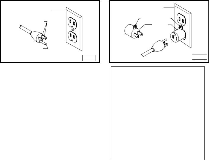
1.Attach the hub of the handle assembly (A) Fig. 1 to the end of the pinion shaft (B). Fasten the handle to the pinion shaft using the special screw (C) and spring (D).
2.Raise the mortising machine head (E) Fig. 2 to the "up" position by turning the handle (A) clockwise.
NOTE: The handle (A) is spring-loaded. Reposition it by pulling it out and moving it on pinion shaft (B).
|
|
|
|
|
|
|
|
|
|
|
|
|
|
|
|
|
|
|
|
|
|
|
B |
|
|
|
|
|
|
|
|
|
|
|
|
|
|
|
|
|
|
|
|
|
|
|
|
|
A |
|
|
|
|
|
|
A |
|
|
|
|||
|
|
|
|
|
|
|
|
|
|
|
|
|
|
|
|
|||||
|
|
|
|
|
|
|
|
|
|
|
|
|
|
|
|
|
||||
|
|
|
|
|
|
|
|
|
D |
|
|
|
|
|
|
|
|
|
|
|
|
|
|
|
|
|
|
|
|
|
|
|
|
|
|
|
|
||||
|
|
|
|
|
|
E |
||||||||||||||
|
|
|
|
|
|
|
|
|
|
|
|
|
|
|
|
|
|
|||
|
|
|
|
|
|
|
|
|
|
|
|
|
|
|
|
|
|
|
|
|
|
|
|
|
|
|
|
|
|
C |
|
|
|
|
|
|
|
|
|
|
|
|
|
|
|
|
|
|
|
|
|
|
|
|
|
|
|
|
|
|
||
|
|
|
|
|
|
|
|
|
|
|
|
|
|
|
|
B |
|
|
||
|
|
|
|
|
|
|
|
|
|
|
|
|
|
|
|
|
|
|
|
|
|
Fig. 1 |
|
|
|
|
|
|
|
|
|
|
|
|
|
|
|
|
Fig. 2 |
|
|
|
|
|
|
|
|
|
|
|
|
|
|
|
|
|
|
|
|
|
|
|
ATTACHING THE HYDRAULIC CYLINDER
Place the head (A) Fig. 3 in the “up” position. Attach the hydraulic cylinder (B) to the two fittings, one located on the back of the head (C) Fig. 3, and the other on the column (D) Fig. 4. Push each end of the hydraulic cylinder on its fitting to secure the cylinder.
|
|
|
|
|
|
|
|
|
|
|
|
|
|
|
|
|
|
|
|
|
|
|
|
|
|
|
|
|
|
D |
|
|
|
|
|
|
|
|
|
|
|
|
|
|
|
|
|
|
||
|
|
|
|
|
A |
|
|
|
|
|
|
|
|
|||
|
|
|
|
|
|
|
|
|
|
|
||||||
|
B |
|
|
|
|
|
|
|
|
|||||||
|
|
|
|
|
|
|
|
|
|
|
|
|
|
|
||
|
|
|
C |
|
|
|
|
|
|
|
|
|
B |
|||
|
|
|
|
|
|
|
|
|
|
|
|
|
|
|
|
|
|
|
|
|
|
|
|
Fig. 3 |
|
|
|
Fig. 4 |
|
|
|
|
|
|
|
|
|
|
|
|
|
|
|
|
|
|
|
|
|
|
ATTACHING THE TOOL AND CHISEL HOLDER
1.Attach the tool and chisel holder (A) Fig. 5 to the back of the column, using the two M6x1x25mm screws (B) and M6 lockwashers.
2.Fig. 6 illustrates the stored chuck key/wrench (C), bushing (F) for use with extra long chisels, and chisels and bits (E).
|
|
|
|
|
|
|
|
|
|
|
|
|
|
|
|
|
|
|
|
|
|
|
|
|
|
|
|
|
|
|
|
|
|
|
|
|
|
|
|
|
|
|
|
|
|
|
|
|
|
|
E |
|
|
|
|
|
|
|
|
|
|
|
|
|
|
C |
|
|
|
|
|
|
|
|
|
|
|
|
|
|
|
|
|
|
|
|
|
|
|
|
|
|
|
|
B |
|
|
||||||||||
|
|
|
|
|
|
|
|
|
|
|
|
|
|
|
|
|
|
|
|
|
|
|
|
|
|
|
|
|
|
|
|
|
|
|
|
|
|
A |
|
|
|
|
|
|
|
|
|
|
|
||||
|
|
|
|
|
B |
|
|
|
|
|
|
|
|
|
|
|
|
|
|
|
|
|
|
|
F |
|
|
|
|
|
|
|
|
||
|
|
|
|
|
|
|
|
|
|
|
|
|
|
|
|
||
|
|
|
|
|
|
|
|
|
|
|
|
|
|
|
|
|
|
|
|
|
|
|
|
|
|
|
A |
||||||||
|
Fig. 5 |
|
|
|
|
|
|
|
|
|
|
|
|
Fig. 6 |
|
|
|
|
|
|
|
|
|
|
|
|
|
|
|
|
|
|
|||
|
|
|
|
|
|
|
|
|
|
|
|
|
|
|
|
|
|
7 - English
FASTENING THE MACHINE TO A SUPPORTING SURFACE
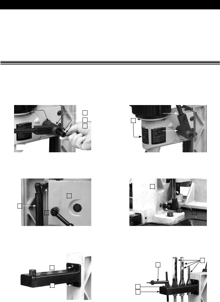
If the machine has any tendency to tip over, slide, or walk on the supporting surface, you must secure the base of the machine to a supporting surface with fasteners (not supplied) through the two holes (A) Fig. 7, located in the mortiser base.
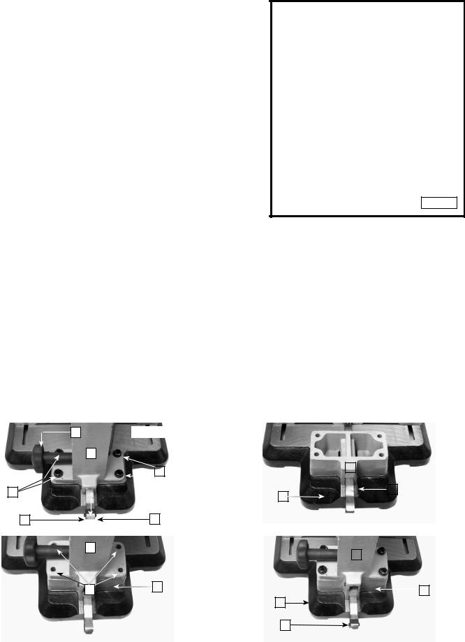
ATTACHING THE CHISEL AND BIT
 Disconnect the machine from the power source!
A |
Fig. 7 |
1. Insert the bit (A) Fig. 8 in the chisel (B).
NOTE: The opening (C) on the side of the chisel (that allows chips to escape) should always face the side - never the front or rear.

 A
A

 B
B

 C
C
Fig. 8
2.Loosen the screw (D) Fig. 9, and push the chisel (B) up through the hole in the head as far as possible. Lower the chisel (B) 1/16" to 3/16" and tighten the set screw (D).
IMPORTANT: When inserting the chisel (B) Fig. 10 into the head, leave a space of 1/16" to 3/16" clearance (F) between the bushing (E) and the shoulder of the chisel (B).
3.Push the bit (A) Fig. 11 up through the chisel and into the chuck (G) as far as it will go. Lock the bit in the chuck using the supplied chuck key.
4.Loosen the set screw (D) Fig. 12, and push the chisel (B) against the bottom of the bushing (E), and tighten the set screw
(D) to provide the proper distance between the cutting lips of the bit and the points of the chisel.
D |
D |

 B
B
E
F
B 
Fig. 9 |
|
Fig. 10 |

 D
D
G 

A
E

 B
B
Fig. 11 |
|
|
|
Fig. 12 |
|
|
|
|
8 - English
5.Adjust the flat portion of the bit to a minimum of 1/16" below the bottom of the chisel. Certain types of wood may require an increase in this gap up to a maximum of 3/16".
ATTACHING THE COLUMN EXTENSION
You can extend the column to mortis taller workpieces. To extend the column:
 Disconnect the machine from the power source!
PUSH THE
CHISEL AGAINST
THE BUSHING
ADJUST THE BIT IN
THE CHUCK TO GIVE
CLEARANCE
1/16" to 3/16" CLEARANCE DEPENDING ON
THE TYPE OF WOOD
Fig. 13
1.Take out the two screws (B) Fig. 14 and remove the rack cover bracket (D).
2.Remove the four screws and flat washers (A) Fig. 14.
3.Rotate handle (E) until the column assembly (C) Fig. 14 moves off the back of the rack and base.
4.Place the column extension (A) Fig. 15 on top of the rack (B). Align the four holes in the column extension (A) Fig. 15 with the four holes in the base (C).
5.Place the column assembly (C) Fig. 16 on top of the column extension (A) and align the four holes (B) in the column assembly with the four holes in the column extension (A).
6.Place a flat washer that was removed in STEP 2 on an M8x1.25x80mm hex head screw.
7.Insert the screw through the hole in the column assembly (C) Fig. 17 and the column extension (A). Thread it into the base (B). Repeat this process for the three remaining holes.
8.Replace the rack cover bracket (D) Fig. 17 that was removed in STEP 1.
9.Loosen the holddown knob (B) Fig. 18 and remove the hold-down. Loosen the set screw (C) and remove the holddown rod (A) and replace with the extended hold-down rod. Tighten the set screw (C). Place the hold-down (B) on the holddown rod and tighten the hold-down handle (B).
|
|
|
|
|
|
|
|
|
|
|
|
|
|
|
|
|
|
|
|
|
|
|
|
|
|
|
|
|
|
|
|
|
|
|
|
|
E |
|
Fig. 14 |
|
|
|
Fig. 15 |
|
|
|
|
|
|
|
|
|
|
||||||||||||
|
|
|
|
|
C |
|
|
|
|
|
|
|
|
|
|
|
|
|
|
|
|
|
|
|
|
|
|
|
|
|
|
|
|
|
|
|
|
|
|
|
|
|
|
|
|
|
|
|
|
|
|
|
|
|
|
|
|
|
|
|
|
|
|
||
|
|
|
|
|
|
|
|
|
|
|
|
|
|
|
|
|
|
|
|
|
|
|
|
A |
||||||||
|
|
|
|
|
|
|
|
|
|
|
A |
|
|
|
||||||||||||||||||
|
|
|
|
|
|
|
|
|
|
|
|
|
|
|
|
|
|
|
|
|
|
|
|
|
|
|
|
|
|
|||
|
|
|
|
|
|
|
|
|
|
|
|
|
|
|
|
|
|
|
|
|
|
|
|
|
|
|
|
|
|
|
|
|
|
A |
|
D |
|
|
|
|
|
|
|
|
|
|
|
|
|
|
|
|
|
|
|
|
|
B |
|
|
|
||||
|
|
|
|
|
|
|
|
|
|
|
|
|
|
C |
|
|
|
|
|
|
|
|
|
|||||||||
|
|
|
|
|
|
|
|
|
|
|
|
|
|
|
|
|
|
|
|
|
|
|
|
|||||||||
|
|
|
|
|
|
|
|
|
|
|
|
|
|
|
|
|
|
|
|
|
|
|
|
|
|
|
|
|||||
|
|
|
|
|
|
|
|
|
|
|
|
|
|
|
|
|
|
|
|
|
|
|
|
|
|
|
|
|
|
|
|
|
|
|
|
|
|
|
|
|
|
|
|
|
|
|
|
|
|
|
|
|
|
|
|
|
|
|
|
|
|
|
|
|
|
|
|
B |
|
|
|
|
|
|
B |
|
|
|
|
|
|
|
|
|
|
|
|
|
|
|
|
|
|
|
|
|
||
|
|
|
|
|
|
|
|
|
|
|
|
|
|
|
|
|
|
|
|
|
|
|
|
|
|
|
|
|
|
|
|
|
|
|
|
|
|
|
|
|
|
|
|
|
|
|
|
|
|
|
|
|
|
|
|
|
|
|
|
|
|
|
|
|
|
|
|
|
|
|
|
|
|
|
|
|
|
|
|
|
|
|
|
|
|
|
|
|
|
|
|
|
|
|
|
|
|
|
|
|
|
|
|
C |
|
|
|
|
|
|
|
|
|
|
|
|
|
|
|
|
|
|
|
|
|
|
|
|
|
|
|
|
|
|
|
|
|
|
|
|
|
|
|
|
|
|
|
|
|
|
|
|
|
|
C |
|
|
|
|
|
|
|||
|
|
|
|
|
|
|
|
|
|
|
|
|
|
|
|
|
|
|
|
|
|
|
|
|
|
|
|
|
||||
|
|
|
|
|
|
|
|
|
|
|
|
|
|
|
|
|
|
|
|
|
|
|
|
|
|
|
|
|
|
|
||
|
|
|
|
|
B |
|
|
|
A |
|
|
|
|
|
|
|
|
|
|
|
|
|
|
|
|
|
||||||
|
|
|
|
|
|
|
|
|
|
|
|
|
|
|
|
|
|
|
|
|
|
|
|
|
|
A |
|
|||||
|
|
|
|
|
|
|
|
|
|
|
|
|
|
|
|
|
|
|
|
|
|
|
|
|
|
|
|
|
|
|||
|
|
|
|
|
|
|
|
|
|
|
|
|
|
|
|
|
|
|
|
|
|
|
|
|
||||||||
|
|
|
|
|
|
|
|
|
|
|
|
|
|
|
|
|
|
|
B |
|||||||||||||
|
|
|
|
|
|
|
|
|
|
|
|
|
|
|
|
|
|
|
|
D |
|
|
||||||||||
|
Fig. 16 |
|
|
|
|
|
|
|
|
|
|
|
|
|
|
|
|
|
Fig. 17 |
|
||||||||||||
|
|
|
|
|
|
|
|
|
|
|
|
|
|
|
|
|
|
|
|
|
|
|
|
|
|
|
|
|||||
|
|
|
|
|
|
|
|
|
|
|
|
|
|
|
|
|
|
|
|
|
|
|
|
|
|
|
|
|
|
|
|
|
|
|
|
|
|
|
|
|
|
|
|
|
|
|
|
|
|
|
|
|
|
|
|
|
|
|
|
|
|
|
|
|
|
9 - English
NOTE: Reverse the procedure to remove the column extension.
 To prevent damage to the unit, place the rack cover over the gear. This action will prevent the cover from being trapped between the rack and the gear.
A
B
C 

Fig. 18
OPERATION
OPERATIONAL CONTROLS AND ADJUSTMENTS
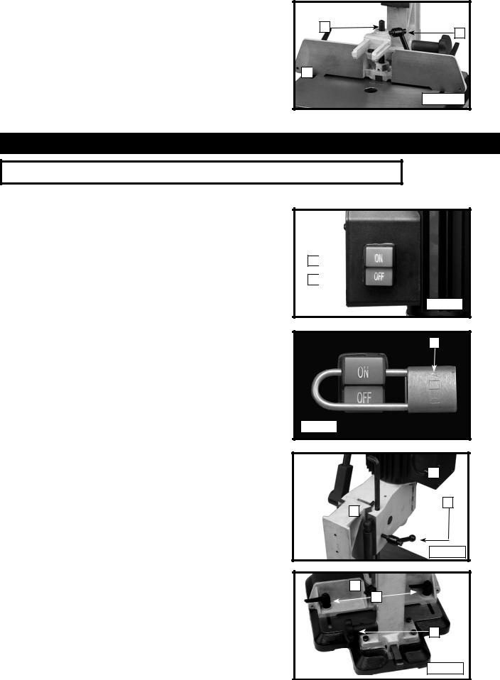
STARTING AND STOPPING THE MACHINE
The power switch is located on the left side of the mortiser. To turn the mortiser “ON”, press the green start button (A) Fig. 19. To stop the mortiser, push the red button (B).
LOCKING SWITCH IN THE “OFF” POSITION
IMPORTANT: When the machine is not in use, the switch should be locked in the "OFF" position to prevent unauthorized use, using a padlock (A) Fig. 20 with a 3/16" diameter shackle.
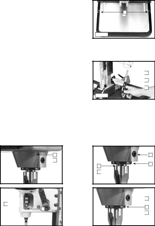
ADJUSTING THE DEPTH STOP ROD
The depth stop rod (A) Fig. 21 limits the depth of the chisel. To adjust the depth stop rod (A), loosen the lever (C) and lower the head. When the head is at the desired location, lower the depth stop rod (A) until it contacts the top of the column (D) and tighten the lever (C).
ADJUSTING THE FENCE
You can move the fence (A) Fig. 22 in or out by loosening the lock handles (B), and rotating the fence rack handle (C). Tighten the handles (B) after the move.
NOTE: The levers (B) are spring-loaded and can be repositioned. Pull out on the lever and reposition it on the serrated nut located underneath the lever.
A

B

Fig. 19
A
Fig. 20

 A
A
C
D
Fig. 21
A
B
C
Fig. 22
10 - English
ADJUSTING THE HOLD-DOWN
The hold-down (C) Fig. 23 prevents the workpiece (E) from lifting as the chisel rises out of the hole. To adjust the hold-down, loosen the handle (F), position the holddown so that it just touches the top of the workpiece (E), then tighten the handle. You can turn the hold-down (C) upside down to accommodate thicker workpieces.
ADJUSTING THE CHISEL PARALLEL TO THE WORKPIECE
C
E
F
Fig. 23
You can adjust the chisel (A) Fig. 24 parallel to the workpiece by loosening the screw (B) and rotating the chisel until the back surface of the chisel is touching the workpiece. Tighten the screw (B).
ADJUSTING THE SLIDING FIT BETWEEN THE HEAD AND THE COLUMN
A dovetail gib (A) Fig. 25 ensures a good sliding fit between the head and the column. Make the adjustment by loosening the two screws (B) and turning the adjusting screws (C). Tighten the two screws (B).
NOTE: The adjustment is correct when no side movement between the gib and the column is evident. Adjust the gib so that is is not so tight as to restrict the sliding movement or so loose that it affects accuracy.

 B
B
C |
A |
B |
|
|
A 

Fig. 24 |
|
Fig. 25 |
1.Keep chisels and bits sharp.
2. A typical mortis operation is illustrated in Fig. 26. Note |
B |
|
|
that the opening (A) in the chisel is to the right. Move your |
|
|
|
workpiece from left to right for subsequent cuts to allow |
|
|
|
|
|
A |
|
chips to escape freely. |
|
|
|
|
|
|
3.Hold the workpiece firmly against the fence. Ensure that the hold-down (B) Fig. 28 is properly adjusted. The rate of penetration of the chisel must be fast enough to prevent
burning at the tip of the bit, but not too fast as to stall the motor. You may encounter smoke from the bit or the
workpiece. Smoke is a natural operating occurrence, caused by friction and burning of resins. Bluing of the chisel after initial use is not indicative of a dull chisel, but rather is a combination of friction and built-up resin on the cutting face of the chisel. You can detect a dull chisel by the amount of excess force required to complete a cut.
4.When performing a through mortise, place a thin piece of wood between the workpiece and the table to prevent “chip-out” at the bottom of the mortise.
11 - English
ROTATING THE COLUMN 180 DEGREES
The column (A) Fig. 27 can be rotated 180 degrees for special cuts. To rotate the column, remove the four screws, two of which are shown at (B), rotate the column (A) 180 degrees, and replace the four screws (B).
You must secure the base to a supporting surface.
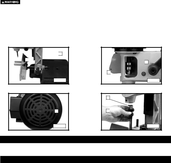
USING BITS WITH EXTRA LONG SHANKS
When using bits with extra long shanks, remove the extension (A) Fig. 28. Insert a screwdriver into the slot (B) Fig. 29 in the end of the armature shaft on top of the motor. Use a chuck key to unscrew and remove the chuck (C) Fig. 28 and extension (A). Remove the extension (A) from the chuck (C) and replace the chuck (C). You can also use the chisel spacer. Place the chisel spacer (D) Fig. 30 on the chisel shank (F) and insert the chisel into the chisel holder. Tighten the chisel holder securely.

 A
A
B 

Fig. 27

 B
B
Fig. 29

 A
A
C 

Fig. 28
F
D 

Fig. 30
TROUBLESHOOTING
For assistance with your machine, visit our website at www.deltamachinery.com for a list of service centers or call the DELTA Machinery help line at 1-800-223-7278 (In Canada call 1-800-463-3582).
MAINTENANCE
KEEP MACHINE CLEAN
Periodically blow out all air passages with dry compressed air. All plastic parts should be cleaned with a soft damp cloth. NEVER use solvents to clean plastic parts. They could possibly dissolve or otherwise damage the material.
 Wear certified safety equipment for eye, hearing and respiratory protection while using compressed air.
FAILURE TO START
Should your machine fail to start, check to make sure the prongs on the cord plug are making good contact in the outlet. Also, check for blown fuses or open circuit breakers in the line.
LUBRICATION & RUST PROTECTION
Apply household floor paste wax to the machine table, extension table or other work surface weekly. Or use a commercially available protective product designed for this purpose. Follow the manufacturer’s instructions for use and safety.
To clean cast iron tables of rust, you will need the following materials: a sheet of medium Scotch-Brite™ Blending Hand Pad, a can of WD-40® and a can of degreaser. Apply the WD-40 and polish the table surface with the Scotch-Brite pad. Degrease the table, then apply the protective product as described above.
12 - English
 Loading...