


Variable Speed Grinder
Meuleuse/Affûteuse à vitesse variable
Rectificadora de velocidad variable
Français (16)
Español (30)
www.DeltaMachinery.com
Instruction Manual
Manuel d’utilisation
Manual de instrucciones
INSTRUCTIVO DE OPERACIÓN, CENTROS
DE SERVICIO Y PÓLIZA DE GARANTÍA.
 LÉASE ESTE INSTRUCTIVO
ANTES DE USAR EL PRODUCTO.
23-198 (6 in.)
23-199 (8 in.)

TABLE OF CONTENTS
IMPORTANT SAFETY INSTRUCTIONS................................... |
2 |
safety guidelines - definitions..................................... |
3 |
GENERAL SAFETY RULES....................................................... |
3 |
ADDITIONAL SPECIFIC SAFETY RULES................................ |
4 |
Power Connections........................................................... |
6 |
Motor Specifications........................................................ |
6 |
Grounding Instructions ................................................ |
6 |
Extension Cords ................................................................. |
7 |
KEY Features and Components..................................... |
7 |
Functional Description................................................... |
7 |
Product Specifications................................................... |
8 |
Unpacking............................................................................... |
8 |
Assembly................................................................................. |
9 |
Attach Spark Shield and Grinding Shield ........................... |
9 |
Attach Tool Rest................................................................... |
9 |
Tool Storage....................................................................... |
10 |
Confirm Tightness of Arbor Nuts....................................... |
10 |
Operation.............................................................................. |
11 |
Starting And Stopping ...................................................... |
11 |
Locking the Machine ......................................................... |
11 |
Using the Variable Speed Control...................................... |
11 |
Using the Flexible Lamp.................................................... |
11 |
Maintenance |
|
Grinding Wheels................................................................. |
12 |
Dressing the Wheels.......................................................... |
12 |
Replacing or Changing Grinding Wheels.......................... |
13 |
Other Recommended Maintenance........................... |
13 |
Accessories......................................................................... |
14 |
Warranty.............................................................................. |
14 |
Replacement Parts.......................................................... |
15 |
Service and Repairs......................................................... |
15 |
FranÇais................................................................................ |
16 |
ESPAÑOL.................................................................................. |
30 |
IMPORTANT SAFETY INSTRUCTIONS
READ AND UNDERSTAND ALL WARNINGS AND OPERATING INSTRUCTIONS BEFORE USING THIS EQUIPMENT. Failure to follow all instructions listed below, may result in electric shock, fire,
and/or serious personal injury or property damage.
Woodworking can be dangerous if safe and proper operating procedures are not followed. As with all machinery, there are certain hazards involved with the operation of the product. Using the machine with respect and caution will considerably lessen the possibility of personal injury. However, if normal safety precautions are overlooked or ignored, personal injury to the operator may result. Safety equipment such
as guards, push sticks, hold-downs, featherboards, goggles, dust masks and hearing protection can reduce your potential for injury. But even the best guard won’t make up for poor judgment, carelessness or inattention. Always use common sense and exercise caution in the workshop. If a procedure feels dangerous, don’t try it. Figure out an alternative procedure that feels safer. REMEMBER: Your personal safety is your responsibility. For additional information please visit our website www.DeltaMachinery.com.


 This machine was designed for certain applications only. DELTA® Power Equipment Corporation strongly recommends that this machine not be modified and/or used for any application other than that for which it was designed. If you have any questions relative to a particular application, DO NOT use the
machine until you have first contacted DELTA® to determine if it can or should be performed on the product.
If you have any questions relative to its application DO NOT use the product until you have written DELTA® Power Equipment Corporation and we have advised you. Contact us online at www.DeltaMachinery.com or by mail at Technical Service Manager, DELTA® Power Equipment Corporation, 4825 Highway 45 North, Jackson, TN 38305.
Information regarding the safe and proper operation of this tool is available from the following sources:
•Power Tool Institute, 1300 Sumner Avenue, Cleveland, OH 44115-2851or online at www.powertoolinstitute.com
•National Safety Council, 1121 Spring Lake Drive, Itasca, IL 60143-3201
•American National Standards Institute, 25 West 43rd Street, 4 floor, New York, NY 10036 www.ansi.org - ANSI 01.1 Safety Requirements for Woodworking Machines
•U.S. Department of Labor regulations www.osha.gov
2

SAFETY GUIDELINES - DEFINITIONS
This manual contains information that is important for you to know and understand. This information relates to protecting YOUR SAFETY and PREVENTING EQUIPMENT PROBLEMS. To help you recognize this information, we use the symbols below. Please read the manual and pay attention to these sections.
Indicates an imminently hazardous situation which, if not avoided, will result in death or serious injury.
Indicates a potentially hazardous situation which, if not avoided, could result in death or serious injury.
Indicates a potentially hazardous situation which, if not avoided, may result in minor or moderate injury.
Used without the safety alert symbol indicates potentially hazardous situation which, if not avoided, may result in property damage.
GENERAL SAFETY RULES
 WARNING FAILURE TO FOLLOW THESE RULES MAY RESULT IN SERIOUS PERSONAL INJURY.
•FOR YOUR OWN SAFETY, READ AND UNDERSTAND THE INSTRUCTION MANUAL BEFORE OPERATING THE UNIT. Learn the unit’s application and limitations as well as the specific hazards peculiar to it.
•KEEP WORK AREA CLEAN. Cluttered areas and benches invite accidents.
•DON’T USE IN DANGEROUS ENVIRONMENT. Don’t use this unit in damp or wet locations, or expose it to rain. Keep work area well-lighted.
•KEEP CHILDREN AND VISITORS AWAY. All children and visitors should be kept a safe distance from work area.
•DISCONNECT UNIT before servicing.
•CHECK DAMAGED PARTS. Before further use of the unit, properly repair or replace any part that is damaged.
 FAILURE TO FOLLOW THESE RULES MAY RESULT IN SERIOUS INJURY.
1.Read and understand the warnings posted on the machine and in this manual. Failure to comply with all of these warnings may cause serious injury.
2.Replace the warning labels if they become obscured or removed.
3.This machine is designed and intended for use by properly trained and experienced personnel only. If you are not familiar with the proper and safe operation of a band saw, do not use until proper training and knowledge have been obtained.
4.Do not use this machine for other than its intended use. If used for other purposes, DELTA® Power Equipment Corporation disclaims any real or implied warranty and holds itself harmless from any injury that may result from that use.
5.Always wear approved safety glasses/face shiiellds while using this grinder.
6.Before operating this grinder, remove tie, riings,, watches and other jewelry, and roll sleeves up past the elbows. Remove all loose clothing and confine long hair. Non-slip footwear or anti-skid floor strips are recommended. Do not wear gloves.
7.Wear ear protectors (plugs or muffs) during extended periods of operation.
8.Some dust created by power sanding, sawing, grinding, drilling and other construction activities
contain chemicals known to cause cancer, birth defects or other reproductive harm. Some examples of these chemicals are:
•Lead from lead based paint.
•Crystalline silica from bricks, cement and other masonry products.
•Arsenic and chromium from chemically treated lumber.
Your risk of exposure varies, depending on how often you do this type of work. To reduce your exposure to these chemicals, work in a well-ventilated area and work with approved safety equipment, such as face or dust masks that are specifically designed to filter out
microscopic particles.
9.Do not operate this machine while tired or under the influence of drugs, alcohol or any medication.
10.Make certain the switch is in the OFF position before connecting the machine to the power source.
11.Make certain the machine is properly grounded.
12.Make all machine adjustments or maintenance with the machine unplugged from the power source.
continued on page 4
3

13.Form a habit of checking to see that all extra equipment such as adjusting keys, wrenches, scrap, stock, and cleaning rags are removed away from the machine before turning on.
14.Keep safety guards in place at all times when the machine is in use. If removed for maintenance purposes, use extreme caution and replace the guards immediately when maintenance is complete.
15.Make sure the tool is firmly secured to a stable work surface before use.
16.Check damaged parts. Before further use of the machine, a guard or other part that is damaged should be carefully checked to determine that it will operate properly and perform its intended function. Check for alignment of moving parts, binding of moving parts, breakage of parts, mounting and any other conditions that may affect its operation. A guard or other part that is damaged should be properly repaired or replaced.
17.Provide for adequate space surrounding work area and non-glare, overhead lighting.
18.Keep the floor around the machine clean and free of scrap material, oil and grease.
19.Keep visitors a safe distance from the work area. Keep children away.
20.Make your workshop child proof with padlocks, master switches or by removing starter keys.
21.Give your work undivided attention. Looking around, carrying on a conversation and “horseplay" are careless acts that can result in serious injury.
22.Maintain a balanced stance at all times so that you do not fall or lean against the tool or its moving parts. Do not overreach or use excessive force to perform any machine operation.
23.Use the right tool at the correct speed and feed rate. Do not force a tool or attachment to do a job for which it was not designed. The right tool will do the job better and safer.
24.Use recommended accessories; improper accessories may be hazardous.
25.Maintain machinery with care. Follow instructions for lubricating and changing accessories.
26.Turn off the machine before cleaning. Use a brush or compressed air to remove dust or debris — do not use your hands.
27.Do not stand on the machine. Serious injury could occur if the machine tips over.
28.Never leave the machine running unattended. Turn the power off and do not leave the machine until it comes to a complete stop.
29.At all times, hold the stock firmly.
30.Do not use this tool for other than it intended use. If used for other purposes, DELTA® Power Equipment Corporation disclaims any real or implied warranty and holds itself harmless for any injury or damage which may result from that use.
Familiarize yourself with the following safety notices used in this manual:
This means that if precautions are not heeded, it may result in minor injury and/or possible machine damage.
This means that if precautions are not heeded, it may result in serious injury or possibly even death.
ADDITIONAL SPECIFIC SAFETY RULES
 Failure to follow these rules may result in serious personal injury.
1.Do not operate this machine until it is completely assembled and installed according to the instructions. A machine incorrectly assembled can cause serious injury.
2.OBTAIN ADVICE from your supervisor, instructor, or another qualified person if you are not thoroughly familiar with the operation of this machine. Knowledge is safety.
3.FOLLOW ALL WIRING CODES and recommended electrical connections to prevent shock or electrocution.
4.ALWAYS USE THE PROVIDED BLOTTER and wheel flanges to mount the grinding wheels on the grinder shaft to prevent wheel damage or accidental separation. Separation can result in fragments flying off the wheel at high speeds.
5.USE ONLY WHEELS suitable for the speed of the machine. Unsuitable grinding wheels can come apart, throwing fragments out at high speeds.
6.USE ONLY WHEELS that have a bore exactly equal to the arbors of the machine. Never attempt to machine an undersized wheel to fit an arbor. Unsuitable grinding wheels can come apart, throwing fragments out at high speeds.
7.DO NOT overtighten wheel nut.
8.DO NOT USE A WHEEL THAT VIBRATES. Dress the grinding wheel, replace it, or replace the bearings of the shaft. Unsuitable grinding wheels can come apart, throwing fragments at high speeds.
9.INSPECT WHEELS before starting the machine for cracks or fragments. REPLACE DAMAGED WHEELS immediately. Parts of the wheel can be thrown at high speeds causing serious injury.
10.ADJUST EYE SHIELDS close to the grinding wheel, and re-adjust as the wheel wears down. Flying sparks are dangerous and can cause fires or explosions.
4

ADDITIONAL SPECIFIC SAFETY RULES
11.ALWAYS MAKE SURE the eye shields are in place, properly adjusted, and secured.
12.ADJUST TOOL RESTS close to the grinding wheel (1/8" separation or less). Tighten the tool rest securely to prevent shifting positions, and re-adjust as the wheel wears down. The workpiece can be drawn into the wheel, causing damage to the workpiece and/or serious injury.
13.Stand to one side before turning the machine "ON". Loose fragments or wheel parts could fly from the wheel at high speeds.
14.NEVER GRIND ON A COLD WHEEL. Run the grinder for one full minute before applying the workpiece. A cold wheel has a tendency to chip. Those fragments could fly from the wheel at high speeds.
15.Never start the machine with the workpiece against the grinding wheel. The workpiece can be drawn into the wheel, causing damage to the machine and/or serious injury.
16.CLEAN THE MACHINE thoroughly when processing different types of workpieces (wood, steel, or aluminum). Combining wood and metal dust can create an explosion or fire hazard. DO NOT GRIND or polish magnesium. Fire will result.
17.NEVER GRIND NEAR FLAMMABLE GAS OR LIQUIDS. Sparks can create a fire or an explosion.
18.AVOID awkward operations and hand positions. A sudden slip could cause a hand to move into the grinding wheel.
19.KEEP ARMS, HANDS, and fingers away from the wheel. The abrasive surfaces can cause serious injury.
20.HOLD THE WORKPIECE FIRMLY against the tool rest. Loss of control of the workpiece can cause serious injury.
21.DRESS THE WHEEL on the face only. Dressing the side of the wheel could cause it to become too thin for safe use.
22.GRIND A WORKPIECE using the face of the grinding wheel only. Loss of control of the workpiece can cause serious injury.
23.NEVER APPLY COOLANT directly to the grinding wheel. Coolant can weaken the bonding strength of the grinding wheel and cause it to fail. Dip the workpiece in water to cool it.
24.DO NOT TOUCH the ground portion of a workpiece until it has cooled sufficiently. Grinding creates heat.
25.PROPERLY SUPPORT LONG OR WIDE workpieces. Loss of control of the workpiece can cause serious injury.
26.Never Perform layout, assembly , or set-up work on the table/work area when the machine is running. A sudden slip could cause a hand to move into the wheel. Severe injury can result.
27.Turn the machine "OFF", disconnect the machine from the power source, and clean the table/work area before leaving the machine. Lock the switch in the "OFF" position to prevent unauthorized use. Someone else might accidentally start the machine and cause serious injury to themselves.
28.ADDITIONAL INFORMATION regarding the safe and proper operation of power tools (i.e. a safety video) is available from the Power Tool Institute, 1300 Sumner Avenue, Cleveland, OH 44115-2851 (www.powertoolinstitute.com). Information is also available from the National Safety Council, 1121 Spring Lake Drive, Itasca, IL 60143-3201. Please refer to the American National Standards Institute ANSI 01.1 Safety Requirements for Woodworking Machines and the U.S. Department of Labor OSHA 1910.213 Regulations.
SAVE THESE INSTRUCTIONS.
Refer to them often and use them to instruct others.
5
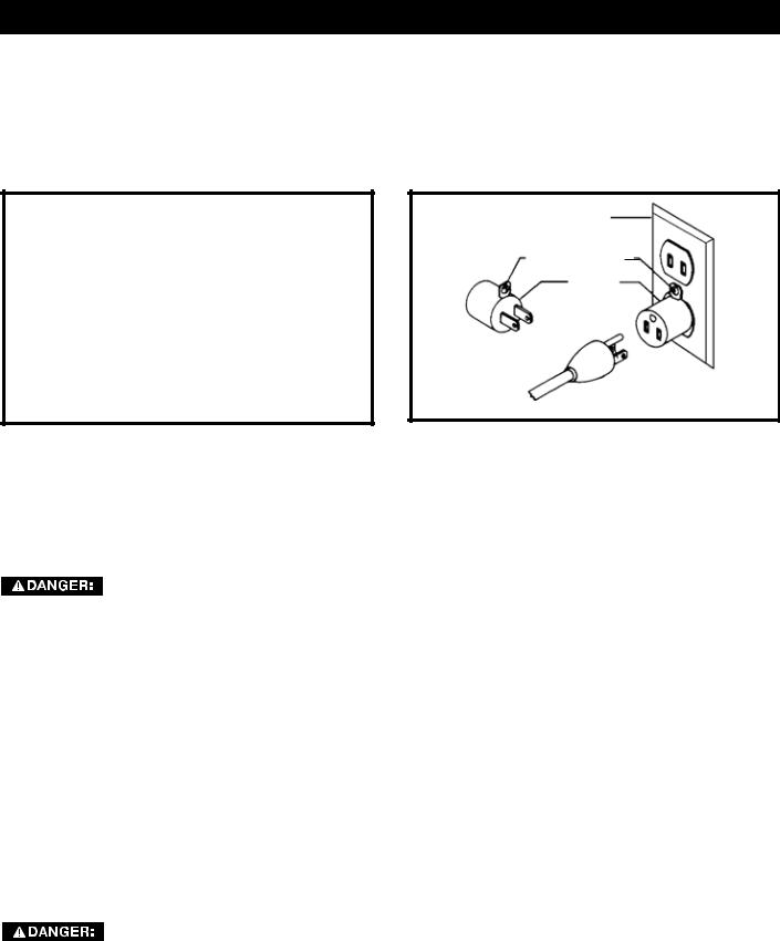
POWER CONNECTIONS
A separate electrical circuit should be used for your machines. This circuit should not be less than #12 wire and should be protected with a 20 Amp time lag fuse. If an extension cord is used, use only 3-wire extension cords which have 3-prong grounding type plugs and matching receptacle which will accept the machine’s plug. Before connecting the machine to the power line, make sure the switch (s) is in the "OFF" position and be sure that the electric current is of the same characteristics as indicated on the machine. All line connections should make good contact. Running on low voltage will damage the machine.

 DO NOT EXPOSE THE MACHINE TO RAIN OR OPERATE THE MACHINE IN DAMP LOCATIONS.
GROUNDED |
GROUNDED OUTLET BOX |
|||
OUTLET BOX |
|
|
|
|
CURRENT |
|
|
GROUNDING |
|
|
|
|
MEANS |
|
CARRYING |
|
|
|
|
|
|
|
|
|
PRONGS |
|
|
|
ADAPTER |
GROUNDING BLADE
IS LONGEST OF THE 3 BLADES
Fig. A |
Fig. B |
MOTOR SPECIFICATIONS
Your machine is wired for 120/240 volts, 60 HZ alternating current. Before connecting the machine to the power source, make sure the switch is in the "OFF" position.
GROUNDING INSTRUCTIONS
THIS MACHINE MUST BE GROUNDED WHILE IN USE TO PROTECT THE OPERATOR FROM ELECTRIC SHOCK.
1. All grounded, cord-connected machines:
In the event of a malfunction or breakdown, grounding provides a path of least resistance for electric current to reduce the risk of electric shock. This machine is equipped with an electric cord having an equipment-grounding conductor and a grounding plug. The plug must be plugged into a matching outlet that is properly installed and grounded in accordance with all local codes and ordinances.
Do not modify the plug provided - if it will not fit the outlet, have the proper outlet installed by a qualified electrician.
Improper connection of the equipment-grounding conductor can result in risk of electric shock. The conductor with insulation having an outer surface that is green with or without yellow stripes is the equipment-grounding conductor. If repair or replacement of the electric cord or plug is necessary, do not connect the equipment-grounding conductor to a live terminal.
Check with a qualified electrician or service personnel if the grounding instructions are not completely understood, or if in doubt as to whether the machine is properly grounded.
Use only 3-wire extension cords that have 3-prong grounding type plugs and matching 3-conductor receptacles that accept the machine’s plug, as shown in Fig. A.
Repair or replace damaged or worn cord immediately.
IN ALL CASES, MAKE CERTAIN THE RECEPTACLE IN QUESTION IS PROPERLY GROUNDED. IF YOU ARE NOT SURE, HAVE A qualified ELECTRICIAN CHECK THE RECEPTACLE.
6
EXTENSION CORDS |
MINIMUM GAUGE EXTENSION CORD |
|||||||
|
|
|
Use proper extension cords. Make |
RECOMMENDED SIZES FOR USE WITH STATIONARY ELECTRIC MACHINES |
||||
|
|
|
sure your extension cord is in good |
Ampere |
Volts |
Total Length |
Gauge of Extension |
|
|
|
|
||||||
condition and is a 3-wire extension cord which has |
Rating |
|
of Cord in |
Cord |
||||
|
|
Feet |
|
|||||
a 3-prong grounding type plug and matching |
|
|
|
|||||
0-6 |
120 |
up to 25 |
18 AWG |
|||||
receptacle which will accept the machine’s plug. |
||||||||
0-6 |
120 |
25-50 |
16 AWG |
|||||
When using an extension cord, be sure to use one |
||||||||
0-6 |
120 |
50-100 |
16 AWG |
|||||
heavy enough to carry the current of the machine. |
||||||||
0-6 |
120 |
100-150 |
14 AWG |
|||||
An undersized cord will cause a drop in line |
6-10 |
120 |
up to 25 |
18 AWG |
||||
voltage, resulting in loss of power and overheating. |
||||||||
6-10 |
120 |
25-50 |
16 AWG |
|||||
The table shows the correct gauge to use |
6-10 |
120 |
50-100 |
14 AWG |
||||
depending on the cord length. If in doubt, use the |
6-10 |
120 |
100-150 |
12 AWG |
||||
next heavier gauge. The smaller the gauge number, |
10-12 |
120 |
up to 25 |
16 AWG |
||||
the heavier the cord. |
10-12 |
120 |
25-50 |
16 AWG |
||||
|
|
|
|
10-12 |
120 |
50-100 |
14 AWG |
|
|
|
|
|
10-12 |
120 |
100-150 |
12 AWG |
|
|
|
|
|
12-16 |
120 |
up to 25 |
14 AWG |
|
|
|
|
|
12-16 |
120 |
25-50 |
12 AWG |
|
|
|
|
|
12-16 |
120 |
|
|
|
|
|
|
|
greater than 50 feet not recommended |
||||
|
|
|
|
|
|
|||
|
|
|
|
|
|
|
|
|
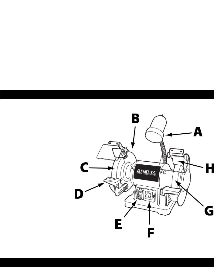
KEY FEATURES AND COMPONENTS
(features start at the top and move counterclockwise around tool)
A. Flexible work lamp
B. Wheel Guard
C. Aluminum oxide grinding wheel
D. Adjustable tool rest
E. On/Off switch with lock-out key
F. Variable speed control
G. Composite grinding wheel
H. Adjustable spark shield
I. On-board storage for included wrench and dressing tool (not shown)
Fig. 1
FUNCTIONAL DESCRIPTION
The DELTA® 23-198 is a 6 in. Variable Speed Grinder and the DELTA® 23-199 is an 8 in. Variable Speed Grinder. They offer superior performance in grinding and sharpening operations and, with the proper accessories, allow the user to remove rust and buff or polish metal. This model comes with a flexible lamp, adjustable tool rests, quick release arbor nut system, and two large eye shields for added safety.
7
PRODUCT SPECIFICATIONS
|
Model 23-198 |
Model 23-199 |
|
|
|
Motor: |
2-1/2" amp, 120V, 1-phase |
5 amp, 120V, 1-phase |
|
|
|
Wheel Speed: |
2,000 to 3,400 rpm |
2,000 to 3,400 rpm |
|
|
|
Wheel Grit: |
36 (coarse), 60 (friable) |
36 (coarse), 60 (friable) |
|
|
|
Wheel (diameter x thickness) |
6" x ¾" |
8" x 1" |
|
|
|
Dimensions (LxWxH) (excludes lamp) |
14-1/2" x 11" x 11" |
16-1/2" x 11" x 12-1/2" |
|
|
|
Base Footprint (LxW) |
9" x 7" |
9-3/4" x 7-1/2" |
|
|
|
Shaft Diameter |
½" |
5/8“ |
|
|
|
Tool Weight |
27lbs |
41lbs |
|
|
|
Unpacking
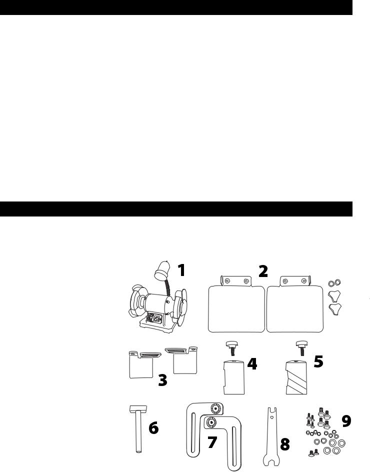
Compare all parts to the list below and check that all parts are present and in good condition. Report any missing or damaged parts to your distributor or dealer. Prior to tool assembly and use, read this manual thoroughly to familiarize yourself with proper assembly, maintenance and safety procedures.
Description (Quantity)
1. 23-198 6 in. Grinder or
23-199 8 in. Grinder (1)
2. Grinding Shields (2)
3. Spark Shields (2)
4. Flat Tool Rest (1)
5. Beveled Tool Rest (1)
6. Wheel Dressing Tool (1)
7.Tool Rest Supports (2)
8.Tool Wrench (1)
9. Hardware Package (1)
10. Operator’s Manual (not shown)
Contents of Hardware Pack
• M5 x 10mm hex screws (4)
• M5 lock washers (4)
• M5 flat washers (6)
• M5 x 12mm carriage bolts (2)
• Threaded thumb knob (2)
•M8 x 10mm hex screws (4)
•M8 flat washers (4)
•M5 x 18mm thumb screw (2)
8

unpacking
Remove any protective materials and coatings from all of the parts and the tool. The protective coatings can be removed by spraying WD-40 on them and wiping it off with a soft cloth. This may need redone several times before all of the protective coatings are removed completely.
If any parts are missing, do not attempt to plug in the power cord and turn “ON" the machine. The machine should only be turned “ON" after all the parts have been obtained and installed correctly.
ASSEMBLY
Attach Spark Shield and Grinding Shield
Refer to Figure 1.
1. Fit two M5 x 10mm hex screws with an M5 lock washer and flat washer. Use assembled hex screws and washers to secure spark shield (A) to the wheel guard. Spark shield should be approximately 1/8" from the grinding wheel.
2. Repeat previous step for second spark shield.
3.Use one M5 x 12mm carriage bolt, inserted through the outermost hole in the spark shield, to attach the grinding shield (B). Secure using one M5 flat washer and a threaded thumb knob.
4. Repeat previous step for second grinding shield.
Figure 1
Attach Tool Rest
Refer to Figure 2.
1.Attach tool rest support (A) to the inner face of the wheel guard using two M8 x 10mm hex screws fitted with M8 flat washers. Finger tighten only. NOTE: The serrated boss on the tool rest support should be facing in toward the center of the tool.
2. Attach tool rest (B) to the tool rest support using one M5 x 18mm thumb screw.
3. Adjust the position of the tool rest support so that the tool rest is approximately 1/8" from the grinding wheel (C).
4.Tighten the two M8 x 10mm hex screws on the tool rest support using the tool wrench provided.
5.Repeat above steps for second tool rest.
Figure 2
9
ASSEMBLY
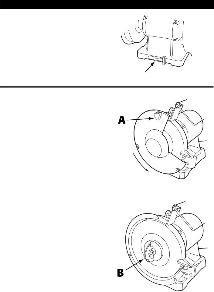
Tool Storage
Your DELTA® 23-198 (6 in.) or 23-199 (8 in.) Grinder has convenient on-board tool storage for the dressing tool provided. The tool holder, shown in Figure 3, is located on the rear of the grinder base.
Figure 3
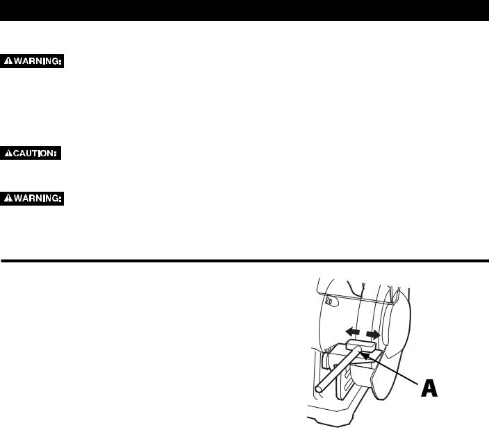
Confirm Tightness of Arbor Nuts
Prior to using your grinder for the first time, it is recommended that you check the tightness of the arbor nuts. To check the tightness on the arbor nuts, do the following:
1.Remove the thumb screws (A) securing the outer face of the wheel guard to the tool frame. See Figure 4.
2. Rotate the wheel guard to free it from the retaining screws and remove guard.
3. Raise both wings of the arbor nut.
4.Firmly grasp the wings of the arbor nut (B) with one hand while using the other hand to keep the wheel from moving. See Figure 5. Tighten the arbor nut as
far as you can.
NOTE: You may also use the 13mm flat wrench
(provided) positioned on the flat of the arbor shaft,
(located between left side wheel and motor) to keep the Figure 4 shaft steady as you tighten the arbor nut.
NOTE: The arbor nut on the right side of the machine tightens by rotating it clockwise, the arbor nut on the left side of the machine tightens by rotating it counterclockwise.
5. Fold the wings of the arbor nut back to their original
position so that they lay flat against the thick outer flange, then re-attach wheel guard.
6. Repeat process for other side.
NOTE: As you use your grinder, the force and direction of the wheel will cause the arbor nut to tighten automatically. However, it is recommended that your periodically check the tightness of the nuts as part of your regular tool maintenance.
Figure 5
10
OPERATION
Starting And Stopping
Make sure that the switch is in the "OFF" position before plugging cord into outlet. Do not touch the plug’s metal prongs when
unplugging or plugging in the cord.
The on/off switch (A) is located on the front of the grinder. See Figure 6. To turn the machine "ON", move the switch up to the "ON" position. To turn the machine "OFF", move the switch down to the "OFF" position.
Locking the Machine
IMPORTANT: When the machine is not in use, the switch should be locked in the "OFF" position to prevent unauthorized use.
To lock the machine, remove the switch key (B) by pulling it straight out. See Figure 7. With the switch key removed, the switch will not operate.
Should the switch toggle be removed while the grinder is running, the machine can be turned "OFF," but cannot be restarted unless the switch toggle is re-inserted.
In the event of a power outage (such as a breaker or fuse trip), always move the switch to the "OFF" position until the main power is
restored.
Using the Variable Speed Control
The grinder is equipped with a variable speed control, located beside the power switch. When the variable speed control knob is positioned at the far left position (counter clockwise), the RPM is 2000. The rotation increases when the variable speed control knob is turned clockwise. Positioned far right, the RPM is 3400.
Using the Flexible Lamp
The flexible lamp operates independently of the grinder. To turn the lamp on and off, rotate the switch located at the top of the lamp.
To reduce the risk of fire, use a 40-watt or smaller, 120 volt, reflector track type light bulb (not supplied). A standard household light
bulb should not be used. The reflector track type light bulb should not extend below the lampshade.
Figure 6
Figure 7
11
MAINTENANCE
Grinding Wheels
The use of accessories and attachments not recommended by
Delta® may result in a risk of injury.
Grinding wheels used with this grinder should be rated for 3600 RPM or higher and have a width of 1" . Grinding wheels for the DELTA® 23-198 must be 6" in diameter with a ½" arbor hole. Grinding wheels for the DELTA® 23-199 must be 8" in diameter with a 5/8" arbor hole.
Using a wheel that is less than ¾" wide for the 6 in. grinder, or 1" wide for the 8 in. grinder, will cause vibration and could
damage the machine.
ALWAYS maintain a distance of 1/8" or less between the grinding wheel and the tool rest. Adjust the tool rests and spark guards as the
grinding wheels decrease in size with use.
The DELTA® 23-198 comes with one 6" aluminum oxide grinding wheel (gray) and one 6" composite grinding wheel (white). The DELTA® 23-199 comes with one 8" aluminum oxide grinding wheel (gray) and one 8" composite grinding wheel (white). For best results, and to properly maintain the grinding wheels, follow these recommendations:
1.Keep the wheels properly dressed.
2.Do not force the work against a cold wheel. Always run the grinding wheel for one full minute before applying a workpiece.
3.Use only balanced wheels with your grinder. Using balanced wheels adds years to the life of the bearings on the grinder. By eliminating the most common source of vibration, your grinding projects will be more accurate.
Dressing the Wheels
Your DELTA® 23-198 (6 in.) Grinder or 23-199 (8in.) Grinder come with a diamond-based wheel dresser included. There is on-board storage for the dresser at the rear of the machine for easy access. Use this tool or any other suitable stick-type dresser to keep your grinding wheels clean and square.
To dress the wheel, refer to Figure 8 and do the following:
1. Bring the dresser (A) forward on the tool rest until it just touches the high point on the face of the wheel.
2.Dress the wheel by moving the dresser back forth.
3.Repeat this operation until the face of the grinding wheel is clean and the edges are square.
Figure 8
12
MAINTENANCE
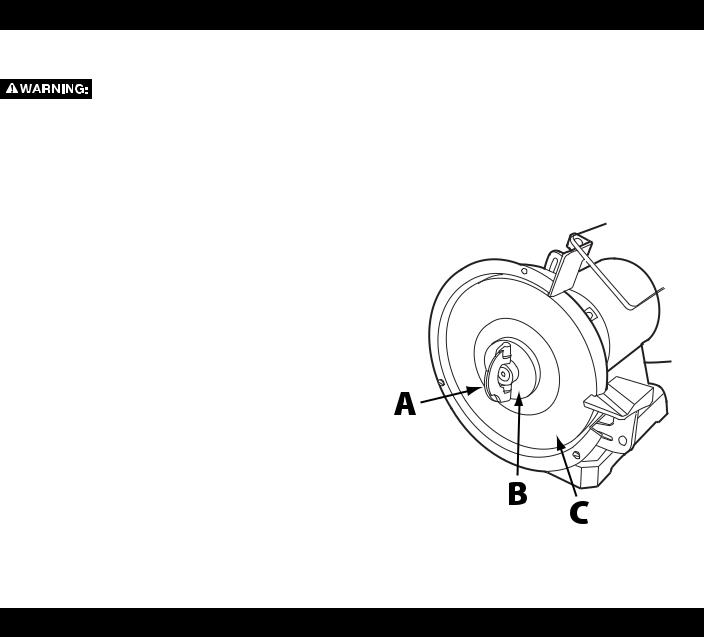
Replacing or Changing Grinding Wheels
Disconnect the machine from the power source.
For steps 1-4, refer to Figures 4 & 5 on page 10:
1.Remove the thumb screws securing the outer face of the wheel guard to the tool frame.
2.Rotate the wheel guard to free it from the retaining screws and remove guard.
3.Raise both wings of the arbor nut.
4.Firmly grasp the wings of the arbor nut with one hand while using the other hand to keep the wheel from moving. Loosen the arbor nut.
NOTE: You may also use the 13mm flat wrench (provided) positioned on the flat of the arbor shaft, (located between left side wheel and motor) to keep the shaft steady as you tighten the arbor nut.
NOTE: To loosen the arbor nut on the right side rotate it counterclockwise. To loosen the arbor nut on the left side rotate it clockwise.
5.Remove the arbor nut (A), wheel flange (B), and old grinding wheel (C), as shown in Figure 10.
6.Place the new grinding wheel on the arbor.
NOTE: Grinding wheels for the 23-198 must be ¾" wide while grinding wheels for the 23-199 must be 1" wide.
7.Place the flange on the arbor and thread the arbor nut on the arbor until the arbor nut makes contact with the arbor flange.
8.Tighten the arbor nut as tight as you can by hand.
9.Push the arbor nut wings out and down to the closed position so that they lay flat against the thick wheel flange.
10.Replace the wheel guard and secure with thumb screws.
Figure 9
Other Recommended Maintenance
1.Periodically blow out all air passages with dry compressed air. All plastic parts should be cleaned with a soft damp cloth. NEVER use solvents to clean plastic parts. They could possibly dissolve or otherwise damage the material.
2.Periodically inspect the tightness of the arbor nuts.
3.Periodically check tightness on all other hardware and listen for any unusual vibrations as you work as these may be a sign of loose hardware.
13

ACCESSORIES
A complete line of accessories is available from your DELTA® Supplier, DELTA® Factory Service Centers, and DELTA® Factory Service Centers, and DELTA® Authorized Service Centers. Please visit our Web Site www. DeltaMachinery.com for an online catalog or for the name or your nearest supplier.
Since accessories other than those offered by DELTA® have not been tested with this product, use of such accessories could be hazardous. For safest operation, only DELTA® recommended
accessories should be used with this product.
WARRANTY
To register your tool for warranty service visit our website at www.DeltaMachinery.com.
Five Year Limited New Product Warranty
DELTA® will repair or replace, at its expense and at its option, any new DELTA® machine, machine part, or machine accessory which in normal use has proven to be defective in workmanship or material, provided that the customer returns the product prepaid to a DELTA® factory service center or authorized service station with proof of purchase of the product within five years and provides DELTA® with reasonable opportunity to verify the alleged defect by inspection. For all refurbished DELTA® product, the warranty period is 180 days. DELTA® will not be responsible for any asserted defect which has resulted from normal wear, misuse, abuse or repair or alteration made or specifically authorized by anyone other than an authorized DELTA® service facility or representative. Under no circumstances will DELTA® be liable for incidental or consequential damages resulting from defective products. Some states do not allow the exclusion or limitation of incidental or consequential damages, so the above limitation or exclusion may not apply to you. This warranty is DELTA®’s sole warranty and sets forth the customer’s exclusive remedy, with respect to defective products; all other warranties, express or implied, whether of merchantability, fitness for purpose, or otherwise, are expressly disclaimed by DELTA®. For further detail of warranty coverage and warranty repair information, visit www.DeltaMachinery.com or call 1-800-223-7278. This warranty gives you specific legal rights and you may have other rights which vary in certain states or provinces.
LATIN AMERICA: This warranty does not apply to products sold in Latin America. For products sold in Latin America, see country specific warranty information contained in the packaging, call the local company or see website for warranty information.
14
 Loading...