


22-555

13 in. BENCH PLANER
RABOTEUSE D'ÉTABLI
DE 330 mm (13 PO)
CEPILLO DE BANCO DE
330 mm (13 PLUG.)
Français (16)
Español (30)
www.DeltaMachinery.com
Instruction Manual
Manuel d’utilisation
Manual de instrucciones
INSTRUCTIVO DE OPERACIÓN, CENTROS
DE SERVICIO Y PÓLIZA DE GARANTÍA.
LÉASE ESTE INSTRUCTIVO
ANTES DE USAR EL PRODUCTO.
22-555

TABLE OF CONTENTS
IMPORTANT SAFETY INSTRUCTIONS ................................... 2
SAFETY GUIDELINES - DEFINITIONS .................................... 3
GENERAL SAFETY RULES ...................................................... 3
ADDITIONAL SPECIFIC SAFETY RULES ............................... 4
POWER CONNECTIONS .......................................................... 6
MOTOR SPECIFICATIONS ....................................................... 6
GROUNDING INSTRUCTIONS ................................................ 6
EXTENSION CORDS ................................................................ 7
KEY FEATURES AND COMPONENTS .................................... 7
FUNCTIONAL DESCRIPTION .................................................. 7
PRODUCT SPECIFICATIONS ................................................... 8
UNPACKING ..............................................................................8
ASSEMBLY ................................................................................. 9
Attach Height Adjustment Handle....................................... 9
Attach Reversible Dust Port ................................................ 9
Connecting to Dust Collector .............................................. 9
OPERATION ............................................................................. 10
Starting and Stopping the Planer ...................................... 10
Locking the Planer Using the Safety Key ......................... 10
Resetting the On-Board Circuit Breaker ........................... 10
Adjusting Cutting Height .................................................. 10
Eliminating Snipe ............................................................... 11
MAINTENANCE ...................................................................... 12
Changing the Cutter Knives .............................................. 12
OTHER RECOMMENDED MAINTENANCE .......................... 12
ACCESSORIES ........................................................................ 13
WARRANTY .............................................................................13
REPLACEMENT PARTS .......................................................... 14
SERVICE AND REPAIRS ......................................................... 14
FRANÇAIS ................................................................................ 16
ESPAÑOL .................................................................................30
IMPORTANT SAFETY INSTRUCTIONS
READ AND UNDERSTAND ALL WARNINGS AND OPERATING INSTRUCTIONS BEFORE USING
THIS EQUIPMENT. Failure to follow all instructions listed below, may result in electric shock, fire, and/or
serious personal injury or property damage.
Woodworking can be dangerous if safe and proper operating procedures are not followed. As with all
machinery, there are certain hazards involved with the operation of the product. Using the machine with
respect and caution will considerably lessen the possibility of personal injury. However, if normal safety
precautions are overlooked or ignored, personal injury to the operator may result. Safety equipment such as
guards, push sticks, hold-downs, featherboards, goggles, dust masks and hearing protection can reduce your potential
for injury. But even the best guard won’t make up for poor judgment, carelessness or inattention. Always use common
sense and exercise caution in the workshop. If a procedure feels dangerous, don’t try it. Figure out an alternative
procedure that feels safer. REMEMBER: Your personal safety is your responsibility. For additional information please
visit our website www.DeltaMachinery.com.
This machine was designed for certain applications only. DELTA® Power Equipment Corporation
strongly recommends that this machine not be modified and/or used for any application other than that
for which it was designed. If you have any questions relative to a particular application, DO NOT use the machine until
you have first contacted DELTA® to determine if it can or should be performed on the product.
If you have any questions relative to its application DO NOT use the product until you have written DELTA® Power
Equipment Corporation and we have advised you. Contact us online at www.DeltaMachinery.com or by mail at Technical
Service Manager, DELTA® Power Equipment Corporation, 99 Roush Street, Anderson, SC 29625.
Information regarding the safe and proper operation of this tool is available from the following sources:
• Power Tool Institute, 1300 Sumner Avenue, Cleveland, OH 44115-2851or online at www.powertoolinstitute.com
• National Safety Council, 1121 Spring Lake Drive, Itasca, IL 60143-3201
• American National Standards Institute, 25 West 43rd Street, 4 floor, New York, NY 10036 www.ansi.org - ANSI 01.1
Safety Requirements for Woodworking Machines
• U.S. Department of Labor regulations www.osha.gov
2

SAFETY GUIDELINES - DEFINITIONS
This manual contains information that is important for you to know and understand. This information relates to protecting
YOUR SAFETY and PREVENTING EQUIPMENT PROBLEMS. To help you recognize this information, we use the
symbols below. Please read the manual and pay attention to these sections.
Indicates an imminently hazardous situation which, if not avoided, will result in death or serious injury.
Indicates a potentially hazardous situation which, if not avoided, could result in death or serious injury.
Indicates a potentially hazardous situation which, if not avoided, may result in minor or moderate injury.
Used without the safety alert symbol indicates potentially hazardous situation which, if not avoided, may
result in property damage.
GENERAL SAFETY RULES
WARNING FAILURE TO FOLLOW THESE RULES MAY RESULT IN SERIOUS PERSONAL INJURY.
For your own safety, read and understand the instruction manual before operating the unit.
•
and limitations as well as the specific hazards peculiar to it.
Keep work area clean.
•
Don’t use in dangerous environment.
•
well-lighted.
Keep children and visitors away.
•
Disconnect unit
•
Check damaged parts.
•
Cluttered areas and benches invite accidents.
Don’t use this unit in damp or wet locations, or expose it to rain. Keep work area
All children and visitors should be kept a safe distance from work area.
before servicing.
Before further use of the unit, properly repair or replace any part that is damaged.
Learn the unit’s application
FAILURE TO FOLLOW THESE RULES MAY RESULT IN SERIOUS INJURY.
1. Read and understand the warnings posted on the
machine and in this manual. Failure to comply with all
of these warnings may cause serious injury.
2. Replace the warning labels if they become obscured
or removed.
3. This machine is designed and intended for use by
3. This machine is designed and intended for use by
properly trained and experienced personnel only.
properly trained and experienced personnel only.
If you are not familiar with the proper and safe
If you are not familiar with the proper and safe
operation of a planer, do not use until proper training
operation of a planer, do not use until proper training
and knowledge have been obtained.
and knowledge have been obtained.
4. Do not use this machine for other than its intended
use. If used for other purposes, DELTA® Power
Equipment Corporation disclaims any real or implied
warranty and holds itself harmless from any injury
that may result from that use.
5. Always wear approved safety glasses/face shields
5. Always wear approved safety glasses/face shields
while using this grinder.
while using this tool.
6. operating this grinder, remove tie, rings, watches
6. Before operating this tool, remove tie, rings, watches
and other jewelry, and roll sleeves up past the
and other jewelry, and roll sleeves up past the
elbows. Remove all loose clothing and confine long
elbows. Remove all loose clothing and confine long
hair. Non-slip footwear or anti-skid floor strips are
hair. Non-slip footwear or anti-skid floor strips are
recommended. Do not wear gloves.
recommended. Do not wear gloves.
7. Wear ear protectors (plugs or muffs) during extended
periods of operation.
8. Some dust created by power sanding, sawing,
grinding, drilling and other construction activities
contain chemicals known to cause cancer, birth
defects or other reproductive harm. Some examples
of these chemicals are:
• Lead from lead based paint.
• Crystalline silica from bricks, cement and other
masonry products.
• Arsenic and chromium from chemically treated lumber.
Your risk of exposure varies, depending on how often
you do this type of work. To reduce your exposure
to these chemicals, work in a well-ventilated area and
work with approved safety equipment, such as face or
dust masks that are specifically designed to filter out
microscopic particles.
9. Do not operate this machine while tired or under the
influence of drugs, alcohol or any medication.
10. Make certain the switch is in the OFF position before
connecting the machine to the power source.
11. Make certain the machine is properly grounded.
12. Make all machine adjustments or maintenance with
the machine unplugged from the power source.
13. Form a habit of checking to see that all extra
equipment such as adjusting keys, wrenches, scrap,
continued on page 4
3

stock, and cleaning rags are removed away from the
machine before turning on.
14. Keep safety guards in place at all times when the
machine is in use. If removed for maintenance
purposes, use extreme caution and replace the
guards immediately when maintenance is complete.
15. Make sure the tool is firmly secured to a stable work
surface before use.
16. Check damaged parts. Before further use of the
machine, a guard or other part that is damaged
should be carefully checked to determine that it will
operate properly and perform its intended function.
Check for alignment of moving parts, binding of
moving parts, breakage of parts, mounting and any
other conditions that may affect its operation. A guard
or other part that is damaged should be properly
repaired or replaced.
17. Provide for adequate space surrounding work area
and non-glare, overhead lighting.
18. Keep the floor around the machine clean and free of
scrap material, oil and grease.
19. Keep visitors a safe distance from the work area.
Keep children away.
20. Make your workshop child proof with padlocks,
master switches or by removing starter keys.
21. Give your work undivided attention. Looking around,
carrying on a conversation and “horse-play" are
careless acts that can result in serious injury.
22. Maintain a balanced stance at all times so that you do
not fall or lean against the tool or its moving parts. Do
not overreach or use excessive force to perform any
machine operation.
23. Use the right tool at the correct speed and feed rate.
Do not force a tool or attachment to do a job for
which it was not designed. The right tool will do the
job better and safer.
24. Use recommended accessories; improper
accessories may be hazardous.
25. Maintain machinery with care. Follow instructions for
lubricating and changing accessories.
26. Turn off the machine before cleaning. Use a brush or
compressed air to remove dust or debris — do not
use your hands.
27. Do not stand on the machine. Serious injury could
occur if the machine tips over.
28. Never leave the machine running unattended. Turn
the power off and do not leave the machine until it
comes to a complete stop.
29. At all times, hold the stock firmly.
30. Do not use this tool for other than it intended use. If
used for other purposes, DELTA® Power Equipment
Corporation disclaims any real or implied warranty
and holds itself harmless for any injury or damage
which may result from that use.
Familiarize yourself with the following safety notices
used in this manual:
This means that if precautions are not heeded, it may
result in minor injury and/or possible machine damage.
This means that if precautions are not heeded, it may
result in serious injury or possibly even death.
ADDITIONAL SPECIFIC SAFETY RULES
Failure to follow these rules may result in serious personal injury.
1. Do not operate this machine until it is completely
assembled and installed according to the
instructions. A machine incorrectly assembled can
cause serious injury
2. Obtain advice from your supervisor, instructor, or
another qualified person if you are not thoroughly
familiar with the operation of this machine.
Knowledge is safety.
3. Follow all wiring codes and recommended electrical
connections to prevent shock or electrocution.
4. Keep knives sharp and free from rust and pitch.
Dull or rusted knives work harder and can cause
kickback.
5. Never turn the machine “on” before clearing the table
of all objects (tools, scraps of wood, etc.).
6. Flying debris can cause serious injury.
7. Never turn the machine “on” with the workpiece
contacting the cutter head. Kickback can occur.
8. Secure the machine to a supporting surface to
prevent the machine from sliding, walking or tipping
over.
9. Properly secure the knives in the cutterhead before
turning the power “on”. Loose blades may be thrown
out at high speeds causing serious injury.
10. Avoid awkward operations and hand positions. A
sudden slip could cause a hand to move into the
knives.
11. Keep arms, hands, and fingers away from the cutter
head, the chip exhaust opening, and the feed rollers
to prevent severe cuts.
4

ADDITIONAL SPECIFIC SAFETY RULES
12. Never reach into the cutterhead area while the
machine is running. Your hands can be drawn into the
knives.
13. Do not stand in line of the workpiece. Kickback can
cause injury.
14. Allow the cutterhead to reach full speed before
feeding a workpiece.
15. When planing bowed stock, place the concave (cup
down) side of the stock on the table and cut with the
grain to prevent kickback.
16. Do not feed a workpiece that is warped, contains
knots, or is embedded with foreign objects (nails,
staples, etc.). Kickback can occur.
17. Do not feed a short, thin, or narrow workpiece into
the machine. Your hands can be drawn into the
knives and/or the workpiece can be thrown at high
speeds. See the “operation” section of this instruction
manual for details.
18. Do not feed a workpiece into the outfeed end of the
machine. The workpiece will be thrown out of the
opposite side at high speeds.
19. Remove shavings only with the power “off” to prevent
serious injury.
20. Properly support long or wide workpieces. Loss of
control of the workpiece can cause serious injury.
21. Never perform layout, assembly or set-up work on
the table/work area when the machine is running.
Serious injury will result.
22. Turn the machine “off”, disconnect it from the power
source, and clean the table/work area before leaving
the machine. Lock the switch in the “off” position
to prevent unauthorized use. Someone else might
accidentally start the machine and cause injury to
themselves or others..
23. Additional information regarding the safe and
proper operation of power tools (i.E. A safety video)
is available from the power tool institute, 1300
sumner avenue, cleveland, oh 44115-2851 (www.
Powertoolinstitute.Com). Information is also available
from the national safety council, 1121 spring lake
drive, itasca, il 60143-3201. Please refer to the
american national standards institute ansi 01.1 Safety
requirements for woodworking machines and the u.S.
Department of labor osha 1910.213 Regulations.
SAVE THESE INSTRUCTIONS.
Refer to them often and use them to instruct others.
5
POWER CONNECTIONS
A separate electrical circuit should be used for your machines. This circuit should not be less than #14 wire and should
be protected with a 20 Amp time lag fuse. If an extension cord is used, use only 3-wire extension cords which have
3-prong grounding type plugs and matching receptacle which will accept the machine’s plug. Before connecting the
machine to the power line, make sure the switch (s) is in the "OFF" position and be sure that the electric current is of
the same characteristics as indicated on the machine. All line connections should make good contact. Running on low
voltage will damage the machine.
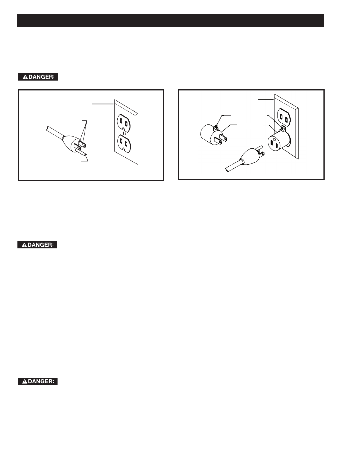
DO NOT EXPOSE THE MACHINE TO RAIN OR OPERATE THE MACHINE IN DAMP LOCATIONS.
GROUNDED
OUTLET BOX
CURRENT
CARRYING
PRONGS
GROUNDING BLADE
IS LONGEST OF THE 3 BLADES
FIG. A FIG. B
GROUNDED OUTLET BOX
GROUNDING
MEANS
ADAPTER
MOTOR SPECIFICATIONS
Your machine is wired for 120 Volts, 60 Hz alternating current. Before connecting the machine to the power source,
make sure the switch is in the “OFF” position.
GROUNDING INSTRUCTIONS
THIS MACHINE MUST BE GROUNDED WHILE IN USE TO PROTECT THE OPERATOR FROM
ELECTRIC SHOCK.
1. All grounded, cord-connected machines:
In the event of a malfunction or breakdown, grounding provides a path of least resistance for electric current to reduce
the risk of electric shock. This machine is equipped with an electric cord having an equipment-grounding conductor and
a grounding plug. The plug must be plugged into a matching outlet that is properly installed and grounded in accordance
with all local codes and ordinances.
Do not modify the plug provided - if it will not fit the outlet, have the proper outlet installed by a qualified electrician.
Improper connection of the equipment-grounding conductor can result in risk of electric shock. The conductor with
insulation having an outer surface that is green with or without yellow stripes is the equipment-grounding conductor. If
repair or replacement of the electric cord or plug is necessary, do not connect the equipment-grounding conductor to a
live terminal.
Check with a qualified electrician or service personnel if the grounding instructions are not completely understood, or if
in doubt as to whether the machine is properly grounded.
Use only 3-wire extension cords that have 3-prong grounding type plugs and matching 3-conductor receptacles that
accept the machine’s plug, as shown in Fig. A.
Repair or replace damaged or worn cord immediately.
IN ALL CASES, MAKE CERTAIN THE RECEPTACLE IN QUESTION IS PROPERLY GROUNDED.
IF YOU ARE NOT SURE, HAVE A QUALIFIED ELECTRICIAN CHECK THE RECEPTACLE.
6
EXTENSION CORDS
Use proper extension cords. Make
sure your extension cord is in good
condition and is a 3-wire extension cord which has
a 3-prong grounding type plug and matching
receptacle which will accept the machine’s plug.
When using an extension cord, be sure to use one
heavy enough to carry the current of the machine.
An undersized cord will cause a drop in line
voltage, resulting in loss of power and overheating.
The table shows the correct gauge to use
depending on the cord length. If in doubt, use the
next heavier gauge. The smaller the gauge number,
the heavier the cord.
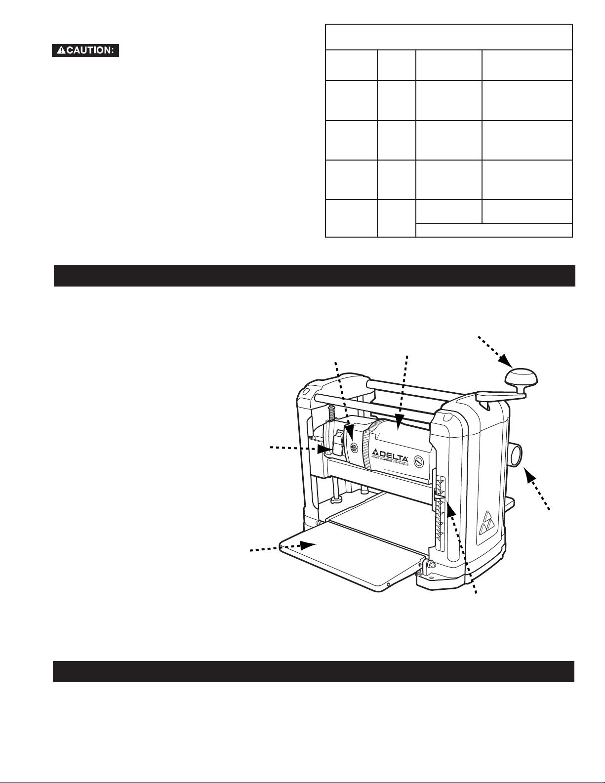
KEY FEATURES AND COMPONENTS
A. Feed Table
MINIMUM GAUGE EXTENSION CORD
RECOMMENDED SIZES FOR USE WITH STATIONARY ELECTRIC MACHINES
Ampere
Rating
0-6
0-6
0-6
0-6
6-10
6-10
6-10
6-10
10-12
10-12
10-12
10-12
12-16
12-16
12-16
Volts Total Length
120
120
120
120
120
120
120
120
120
120
120
120
120
120
120
of Cord in
Feet
up to 25
25-50
50-100
100-150
up to 25
25-50
50-100
100-150
up to 25
25-50
50-100
100-150
up to 25
25-50
GREATER THAN 50 FEET NOT RECOMMENDED
Gauge of Extension
Cord
18 AWG
16 AWG
16 AWG
14 AWG
18 AWG
16 AWG
14 AWG
12 AWG
16 AWG
16 AWG
14 AWG
12 AWG
14 AWG
12 AWG
B. ON/OFF Switch
C. Circuit Breaker Reset
D. 15 Amp, 120V Motor
E. Height Adjustment Handle
F. 2” Reversible Dust Port
G. Height Indicator
A
B
C
D
E
F
G
FUNCTIONAL DESCRIPTION
The DELTA® 22-555 is a 13" (317mm) Portable Planer. This planer can handle workpieces up to 13" (317mm) wide
and 6" (152mm) thick. The maximum depth of cut is 3/32" (2.4 mm). The 22-555 features a powerful 15 Amp, 120 Volt
motor, a two-knife cutter head with double-edged reversible knives, knife-installation tool and wrench.
7
PRODUCT SPECIFICATIONS
4
Cuts Per Minute 18,800
Feed Rate 28ft./min.
Max. Cut Depth (per pass) 3/32”
Max. Cutting Width 12-½“
Max. Cutting Height 6”
Cutterhead Speed 9,400 RPM
Tool Dimensions (LxWxH) 21-5/8” x 23-5/8” x 20-1/8”
Motor 15 Amp, 120V
Net Weight 58 lbs
Knife Type Double-edge reversible
Number of Knives 2
Knife Size (L x W x T) 320mm x12mm x1.5mm
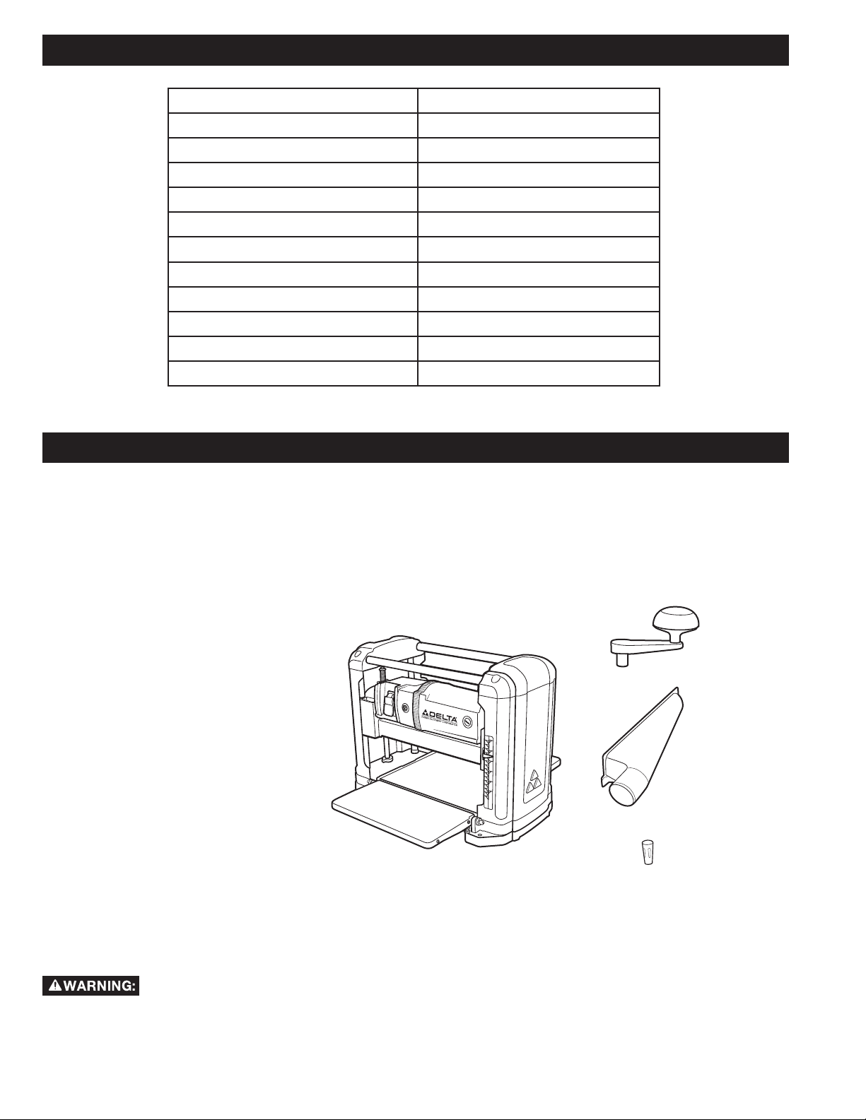
UNPACKING
Compare all parts to the list below and check that all parts are present and in good condition. Report any missing or
damaged parts to your distributor or dealer. Prior to tool assembly and use, read this manual thoroughly to familiarize
yourself with proper assembly, maintenance and safety procedures.
DESCRIPTION (QUANTITY)
1. DELTA® Model #22-555 Planer (1)
2. Height Adjustment Handle (1)
3. Reversible 2” Dust Port (1)
4. Knife Transfer Tool (2)
5. T-wrench (not shown)
HARDWARE PACKAGE
• 4mm T-handle Hex Wrench
• M5x16mm Hex Head Screw (1)
• M5 Flat Washer
• M6x15mm Lock Knob (2)
1
2
3
Remove any protective materials and coatings from all of the parts and the tool. The protective coatings can be removed
by spraying WD-40 on them and wiping it off with a soft cloth. This may need redone several times before all of the
protective coatings are removed completely.
If any parts are missing, do not attempt to plug in the power cord and turn “ON” the machine. The
machine should only be turned “ON” after all the parts have been obtained and installed correctly.
8
ASSEMBLY
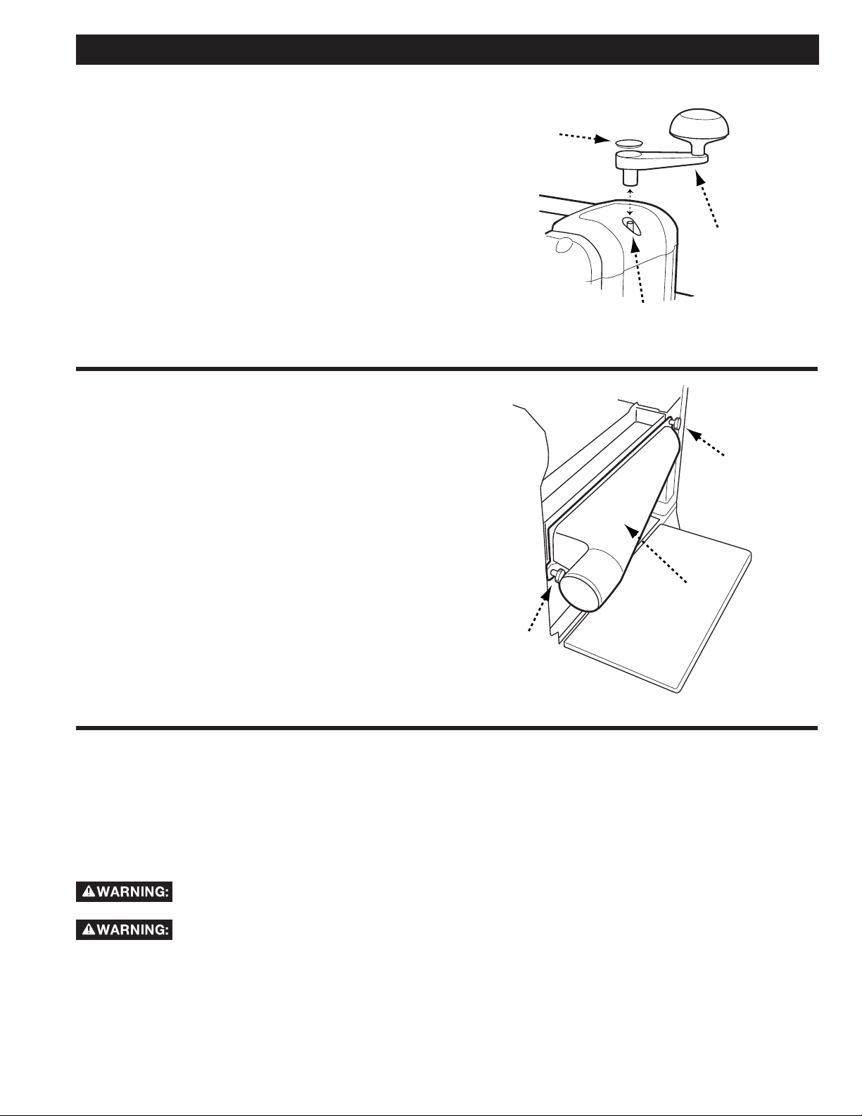
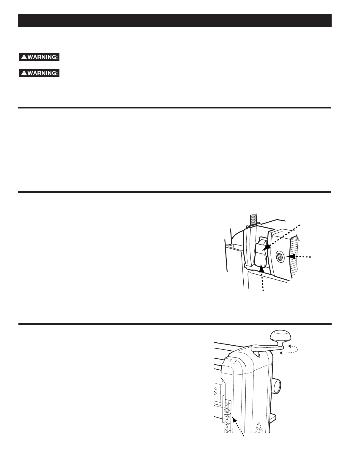
ATTACH HEIGHT ADJUSTMENT HANDLE
Refer to Figure 1
1. Remove the rubber cap (A) from the top of the height
adjustment crank shaft (B).
2. Use an M5 x 16mm hex head screw, M5 flat washer,
and supplied t-handle hex wrench to secure the
height adjustment handle to shaft (C).
3. Replace the rubber cap.
ATTACH REVERSIBLE DUST PORT
Refer to Figure 2
The 22-555 planer features a reversible dust port that can
be attached for left-sided or right-sided dust collection.
To attach the dust port:
1. Secure the dust port (A) to the tool housing on both
ends use the two M6 x 15mm lock knobs (B).
A
B
C
FIGURE 1
B
A
B
FIGURE 2
CONNECTING TO DUST COLLECTOR
A planer creates a large amount of fine particles while in use. It is strongly recommended that you connect the planer to
a shop vacuum or dust collector. Your DELTA® Bench Planer is equipped with a 2” dust port that must be connected
to a vacuum hose to ensure safe operation. Using a 2" to 4" adapter, sold separately, will enable you to connect your
planer to most dust collectors that use a 4” hose.
Do not attempt to operate this tool without first connecting it to an adequate dust collection
system.
Always turn on the dust collector before starting the planer and always stop the planer before
turning off the dust collector.
9
OPERATION
A
STARTING AND STOPPING THE PLANER
Make sure that the switch is in the "OFF" position before plugging cord into outlet. Do not touch
the plug’s metal prongs when unplugging or plugging in the cord.
In the event of a power outage (such as a breaker or fuse trip), always move the switch to the
"OFF" position until the main power is restored.
The ON/OFF switch (A), indicated in Figure 3, is located on the front of the cabinet. To turn the machine “ON,” move the
switch to the up position. To turn the machine “OFF,” move the switch to the down position.
LOCKING THE PLANER USING THE SAFETY KEY
1. This machine uses a safety key (B), shown in Figure 3,
that enables you to lock the tool in the “OFF” position
when not in use.
IMPORTANT: When the machine is not in use, the
switch should be locked in the "OFF" position to prevent
unauthorized use.
2. To lock the machine, remove the safety key by pulling
it straight out. With the safety key removed, the
switch will not operate.
3. Should the safety key be removed while the tool
is running, the machine can be turned "OFF,"
but cannot be restarted unless the safety key is
re-inserted.
RESETTING THE ON-BOARD CIRCUIT BREAKER
As an additional safety feature, the DELTA® 22-555 has an on-board
circuit breaker (C), shown in Figure 3. Should the motor become
overloaded or should a power surge occur while the machine is
operating, the circuit breaker will trip, cutting power to the machine.
In the event the breaker trips, do the following:
1. Turn the machine off and unplug the power cord.
2. Raise the cutterhead and remove the workpiece from the machine.
3. Wait 2 to 3 minutes or until the motor housing is cool to the touch,
then depress the on-board circuit breaker reset.
4. Plug the power cord in and restart the machine using the ON/OFF
switch.
5. If the machine fails to start, allow the motor to cool further and
attempt to reset the breaker again.
B
C
FIGURE 3
ADJUSTING CUTTING HEIGHT
Refer to Figure 4
Your DELTA® 22-555 Bench Planer can accept stock up
to 6” in height and has a maximum cutting depth of 3/32”
per pass. To adjust the height of the cutterhead:
1. Rotate the Height Adjustment Handle until the Height
Indicator (A) is pointing to the desired height. Turning
the handle clockwise raises the cutterhead while
turning it counterclockwise lowers it. One complete
revolution of the Height Adjustment Handle moves
the cutterhead 1/16”.
FIGURE 4
10
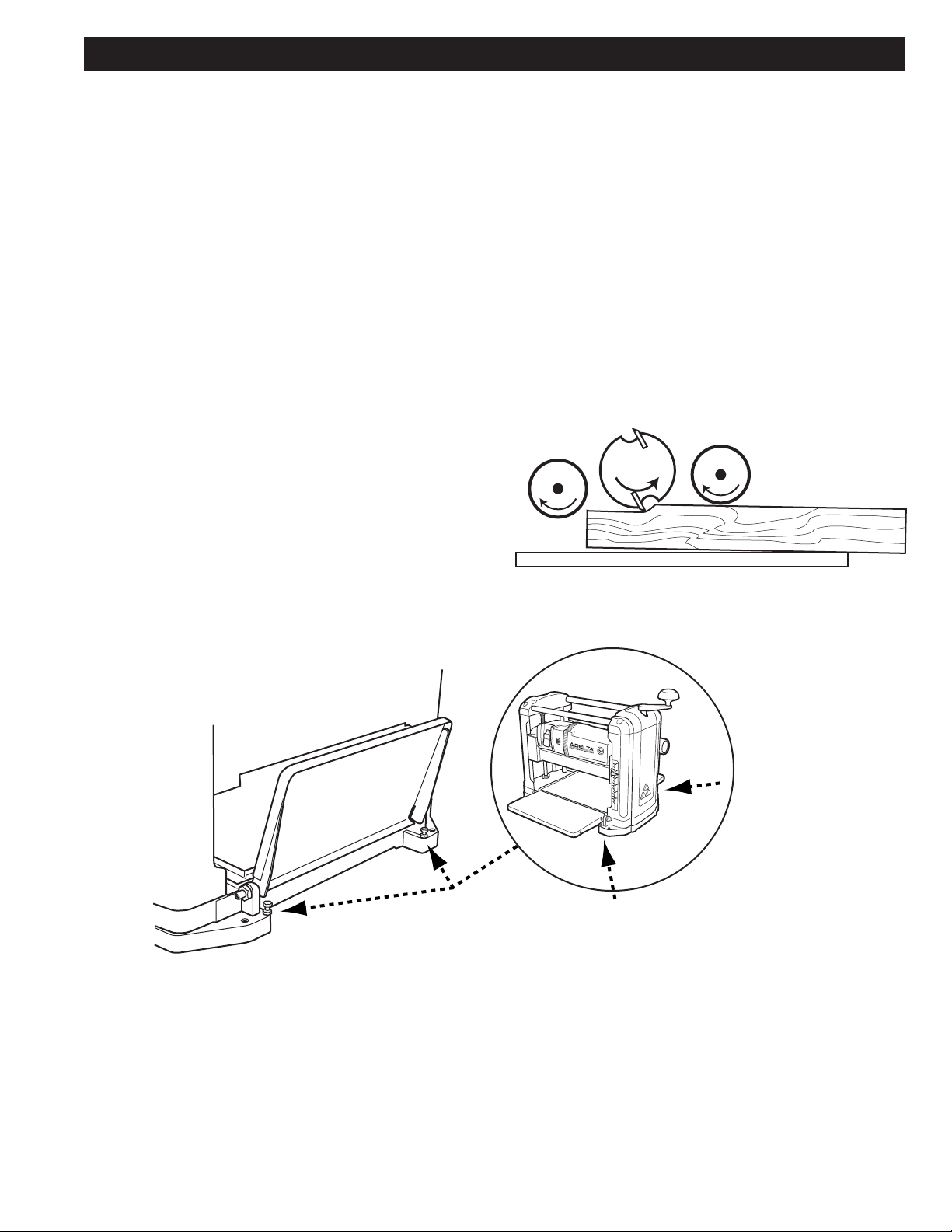
ELIMINATING SNIPE
OPERATION
Snipe is a short depression created at the beginning
and/or end of a board after it passes through the
planer. Figure 5 shows how snipe occurs when a board
enters the cutting area of the planer with the leading
end elevated. The same effect can be created when
the trailing end of the board becomes elevated as the
workpiece exits the planer.
There are a few ways you can control snipe.
The most common cause of snipe is failure to fully
support the workpiece as the leading end enters the
planer and as the trailing end exits the planer. This can
be addressed by securely holding the workpiece to the
surface of the infeed table and not allowing the leading
end to elevate as it contacts the cutterhead.
If, after trying the above, snipe is still present,
try lessening the depth of cut by slightly raising the
height of the cutterhead (see previous section, “Height
Adjustment”).
If the workpiece continues to exhibit snipe, you may
need to adjust the height of the infeed and or outfeed
table. To do this, see Figure 6, then:
1. Fold the infeed and outfeed tables up in order to
locate the two infeed (A) and two outfeed (B) stop
screws.
2. Using a 10mm open wrench, loosen the retaining
nuts.
3. Adjust the stop screws, one set at a time, making
sure that they are at the same height. To check the
screw height, lower the table and confirm that both
screw heads are flush against the bottom of the table.
4. Re-test for snipe.
FIGURE 5
FIGURE 6
11
B
A
MAINTENANCE
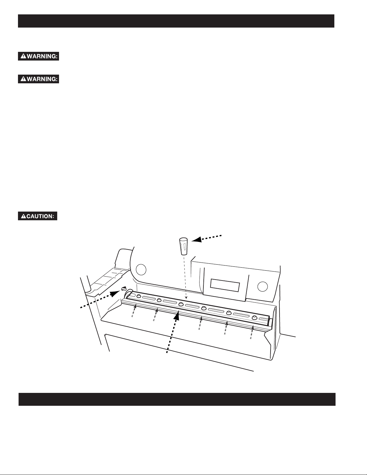
CHANGING OR REVERSING KNIVES
Disconnect the machine from the
power source before making any
adjustments!
Planer knives are dangerously sharp.
Use extreme caution when inspecting,
removing, sharpening, or replacing knives into the cutter
head. Failure to comply may cause serious injury.
1. Remove the dust chute by unscrewing the two lock
knobs shown in Figure 2.
2. Remove the two lock knobs securing the cutterhead
cover to the main casting and remove the cover. The
cutterhead and the knives will now be exposed.
3. Lock the cutterhead in place. To do this, refer to
Figure 7 and ensure the red spring-loaded lock tab (A)
is in the forward position. Then carefully and slowly
rotate the cutterhead until the tab locks in place and
the cutterhead does not move.
4. Using the T-handle hex wrench supplied, loosen the
six screws (B) securing each knife hold down bar and
the knife to the cutterhead.
5. Use the magnetic end of the knife removal tool (C) to
carefully lift off the hold down bar and then the knife.
Blades are sharp! Use great care when
hands are around blade area!
6. Carefully install the new knife or rotate the existing
knife, ensuring the pins on the cutterhead align with
the elongated holes in the knife.
7. Replace the hold down bar, making sure that the two
pins on the cutterhead are aligned with the two small
holes in the hold down bar.
8. Replace and retighten the six screws.
9. Unlock the cutterhead by moving the red springloaded lock tab forward and carefully rotating the
cutterhead until the second knife is exposed and the
cuttterhead locks into place.
10. Repeat Steps 4 – 8 to replace the second knife.
11. Replace the cutterhead cover. Ensure the notches in
the cover align with the threaded holes and the cover
is fully seated in the recess.
12. Replace the dust chute and re-secure with the two
lock knobs.
C
A
B
FIGURE 7
OTHER RECOMMENDED MAINTENANCE
1. Periodically blow out all air passages with dry compressed air. All plastic parts should be cleaned with a soft damp
cloth. NEVER use solvents to clean plastic parts. They could possibly dissolve or otherwise damage the material.
2. Periodically check tightness on all other hardware and listen for any unusual vibrations as you work as these may be
a sign of loose hardware.
12

ACCESSORIES
A complete line of accessories is available from your DELTA® Supplier, DELTA® Factory Service Centers, and DELTA®
Factory Service Centers, and DELTA® Authorized Service Centers. Please visit our Web Site www.DeltaMachinery.
com for an online catalog or for the name or your nearest supplier.
Since accessories other than those offered by DELTA® have not been tested with this product,
use of such accessories could be hazardous. For safest operation, only DELTA® recommended
accessories should be used with this product.
WARRANTY
To register your tool for warranty service visit our website at www.DeltaMachinery.com.
FIVE YEAR LIMITED WARRANTY
Delta® Power Equipment Corporation
1. WHAT IS COVERED. Delta Power Equipment Corporation (“Company”) will repair or replace, at its option, any new or factory refurbished
DELTA® machine or service part which is purchased at retail in the United States or Canada and which in normal use has proven to be defective
in workmanship or material, subject to the conditions stated in this Limited Warranty. This Limited Warranty covers only materials and labor.
All transportation costs are Customer’s responsibility.
2. WARRANTY PERIOD. All warranty claims must be submitted within five years from the date of retail purchase. For all service parts and
factory refurbished DELTA® machines, the warranty period is 180 days.
3. HOW TO OBTAIN SERVICE. To obtain warranty service, you must return the defective product, at your expense, to a service center authorized
by Company to perform warranty service (a “DELTA® Authorized Service Center”) within the applicable warranty period, together with
acceptable proof of purchase, such as your original receipt bearing the date of purchase, or product registration number. Company reserves
the right to restrict warranty claim service to the country where the purchase was made and/or to charge for the cost to export service parts
or provide warranty service in a different country. On-line purchases are deemed made in the United States. For the location of your nearest
DELTA® Authorized Service Center, call Company’s Customer Care Center at (800) 223-7278.
4. EXCLUSIONS.
· Company does not offer any warranty on products purchased in used or damaged condition.
· Company does not warranty any products purchased outside the United States or Canada
· Company will not be responsible for any damage that has resulted from normal wear, misuse, abuse or any repair or alteration made by
anyone other than a DELTA® Authorized Service Center or a designated representative of Company’s Customer Care Center.
· All IMPLIED WARRANTIES are expressly limited to the warranty period identified above.
· Under no circumstances will Company be liable for INCIDENTAL OR CONSEQUENTIAL damages.
· This limited warranty is Company’s sole warranty and sets forth the customer’s exclusive remedy with respect to defective products; all other
warranties, express or implied, whether of merchantability, fitness for purpose, or otherwise, are expressly disclaimed by Company, except as
stated above.
Some states do not allow the exclusion or limitation of incidental or consequential damages, or the limitation of implied warranties, so the
above limitations or exclusions may not apply to you. This warranty gives you specific legal rights and you may have other rights which vary
in certain states or provinces. For further details of warranty coverage and warranty repair information, call (800) 223-7278. To register your
products online, we encourage you to visit our website and register for a FREE DELTA Member Account at http://www.deltamachinery.com/
register.
LATIN AMERICA: This warranty does not apply to products sold in Latin America. For products sold in Latin America, see country
specific warranty information contained in the packaging, call the local company or see website for warranty information.
13

PARTS, SERVICE OR WARRANTY ASSISTANCE
All DELTA® machines and accessories are manufactured to high quality standards and are serviced by a network of
DELTA® Factory Service Centers and DELTA® Authorized Service Centers. To obtain additional information regarding
your DELTA® quality product or to obtain parts, service, warranty assistance, or the location of the nearest service center,
please call 1-800-223-7278.
REPLACEMENT PARTS
Use only identical replacement parts. For a parts list or to order parts, visit our website at www.DeltaMachinery.
com. You can also order parts from your nearest factory-owned branch, Authorized Warranty Service Center or by
calling Technical Service Manager at 1-800-223-7278 to receive personalized support from one of our highly-trained
representatives.
FREE WARNING LABEL REPLACEMENT
If your warning labels become illegible or are missing,
call
1-800-223-7278
for a free replacement.
SERVICE AND REPAIRS
All quality tools will eventually require servicing and/or replacement of parts. For information
about DELTA® Power Equipment Corporation, its factory-owned branches, or to locate
an Authorized Warranty Service Center, visit our website at www.DeltaMachinery.com
or call our Customer Care Center at 1-800-223-7278. All repairs made by our service centers are fully guaranteed
against defective material and workmanship. We cannot guarantee repairs made or attempted by others. By calling
this number you can also find answers to most frequently asked questions 24 hours/day.
You can also write to us for information at D ELTA® Power Equipment Corporation, 99 Roush Street, Anderson,
SC 29625 - Attention: Technical Service Manager. Be sure to include all of the information shown on the
nameplate of your tool (model number, type, serial number, date code, etc.)
141516
 Loading...