


Sidekick
10" Compound Slide Saw
(Models 36-240 and 36-250)
Bench Model 36-240 Shown
PART NO. 902096 (014)
Copyright © 2001 Delta Machinery
To learn more about DELTA MACHINERY |
ESPAÑOL: PÁGINA 33 |
visit our website at: www.deltamachinery.com. |
|
|
|
For Parts, Service, Warranty or other Assistance, |
|
please call 1-800-223-7278 (In Canada call 1-800-463-3582).
MANUAL INSTRUCTION

SAFETY RULES
Woodworking can be dangerous if safe and proper operating procedures are not followed. As with all machinery, there are certain hazards involved with the operation of the product. Using the machine with respect and caution will considerably lessen the possibility of personal injury. However, if normal safety precautions are overlooked or ignored, personal injury to the operator may result. Safety equipment such as guards, push sticks, hold-downs, featherboards, goggles, dust masks and hearing protection can reduce your potential for injury. But even the best guard won’t make up for poor judgment, carelessness or inattention. Always use common sense and exercise caution in the workshop. If a procedure feels dangerous, don’t try it. Figure out an alternative procedure that feels safer. REMEMBER: Your personal safety is your responsibility.
This machine was designed for certain applications only. Delta Machinery strongly recommends that this machine not be modified and/or used for any application other than that for which it was designed. If you have any questions relative to a particular application, DO NOT use the machine until you have first contacted Delta to determine if it can or should be performed on the product.
Technical Service Manager
Delta Machinery
4825 Highway 45 North
Jackson, TN 38305
(IN CANADA: 505 SOUTHGATE DRIVE, GUELPH, ONTARIO N1H 6M7)
WARNING: FAILURE TO FOLLOW THESE RULES MAY RESULT IN SERIOUS PERSONAL INJURY
1.FOR YOUR OWN SAFETY, READ INSTRUCTION MANUAL BEFORE OPERATING THE TOOL. Learn the tool’s application and limitations as well as the specific hazards peculiar to it.
2.KEEP GUARDS IN PLACE and in working order.
3.ALWAYS WEAR EYE PROTECTION.
4.REMOVE ADJUSTING KEYS AND WRENCHES. Form habit of checking to see that keys and adjusting wrenches are removed from tool before turning it “on”.
5.KEEP WORK AREA CLEAN. Cluttered areas and benches invite accidents.
6.DON’T USE IN DANGEROUS ENVIRONMENT. Don’t use power tools in damp or wet locations, or expose them to rain. Keep work area well-lighted.
7.KEEP CHILDREN AND VISITORS AWAY. All children and visitors should be kept a safe distance from work area.
8.MAKE WORKSHOP CHILDPROOF – with padlocks, master switches, or by removing starter keys.
9.DON’T FORCE TOOL. It will do the job better and be safer at the rate for which it was designed.
10.USE RIGHT TOOL. Don’t force tool or attachment to do a job for which it was not designed.
11.WEAR PROPER APPAREL. No loose clothing, gloves, neckties, rings, bracelets, or other jewelry to get caught in moving parts. Nonslip footwear is recommended. Wear protective hair covering to contain long hair.
12.ALWAYS USE SAFETY GLASSES. Wear safety glasses. Everyday eyeglasses only have impact resistant lenses; they are not safety glasses. Also use face or dust mask if cutting operation is dusty. These safety glasses must conform to ANSI Z87.1 requirements. Note: Approved glasses have Z87 printed or stamped on them.
13.SECURE WORK. Use clamps or a vise to hold work when practical. It’s safer than using your hand and frees both hands to operate tool.
14.DON’T OVERREACH. Keep proper footing and balance at all times.
15.MAINTAIN TOOLS IN TOP CONDITION. Keep tools sharp and clean for best and safest performance. Follow instructions for lubricating and changing accessories.
16.DISCONNECT TOOLS before servicing and when changing accessories such as blades, bits, cutters, etc.
17.USE RECOMMENDED ACCESSORIES. The use of accessories and attachments not recommended by Delta may cause hazards or risk of injury to persons.
18.REDUCE THE RISK OF UNINTENTIONAL STARTING. Make sure switch is in “OFF” position before plugging in power cord. In the event of a power failure, move switch to the “OFF” position.
19.NEVER STAND ON TOOL. Serious injury could occur if the tool is tipped or if the cutting tool is accidentally contacted.
20.CHECK DAMAGED PARTS. Before further use of the tool, a guard or other part that is damaged should be carefully checked to ensure that it will operate properly and perform its intended function – check for alignment of moving parts, binding of moving parts, breakage of parts, mounting, and any other conditions that may affect its operation. A guard or other part that is damaged should be properly repaired or replaced.
21.DIRECTION OF FEED. Feed work into a blade or cutter against the direction of rotation of the blade or cutter only.
22.NEVER LEAVE TOOL RUNNING UNATTENDED. TURN POWER OFF. Don’t leave tool until it comes to a complete stop.
23.DRUGS, ALCOHOL, MEDICATION. Do not operate tool while under the influence of drugs, alcohol or any medication.
24.MAKE SURE TOOL IS DISCONNECTED FROM POWER SUPPLY while motor is being mounted, connected or re-connected.
25.THE DUST GENERATED by certain woods and wood products can be injurious to your health. Always operate machinery in well ventilated areas and provide for proper dust removal. Use wood dust collection systems whenever possible.
26. WARNING: SOME DUST CREATED BY POWER SANDING, SAWING, GRINDING, DRILLING, AND OTHER CONSTRUCTION ACTIVITIES contains chemicals known to cause cancer, birth defects or other reproductive harm. Some examples of these chemicals are:
·lead from lead-based paints,
·crystalline silica from bricks and cement and other masonry products, and
·arsenic and chromium from chemically-treated lumber.
Your risk from these exposures varies, depending on how often you do this type of work. To reduce your exposure to these chemicals: work in a well ventilated area, and work with approved safety equipment, such as those dust masks that are specially designed to filter out microscopic particles.
SAVE THESE INSTRUCTIONS. Refer to them often and use them to instruct others.
2
ADDITIONAL SAFETY RULES FOR COMPOUND SLIDE SAWS
1.USE ONLY CROSSCUT SAW BLADES. WHEN USING CARBIDE TIPPED BLADES MAKE SURE THEY HAVE A ZERO DEGREE OR NEGATIVE HOOK ANGLE. DO NOT USE BLADES WITH DEEP GULLETS AS THEY CAN DEFLECT AND CONTACT GUARD.
2.DO NOT operate the tool until it is completely assembled and installed according to the instructions.
3.IF YOU ARE NOT thoroughly familiar with the operation of compound slide saws, obtain advice from your supervisor, instructor or other qualified person.
4.SLIDE CUTTING BY PULLING the saw towards the operator can be dangerous, causing the saw to kick upwards and towards the operator. Always PUSH the saw forward, away from the operator, and towards the fence when slide cutting.
5.WHEN USING THE SAW AS A MITER SAW AND MAKING CHOP CUTS, MAKE SURE the saw sliding mechanism is locked in place to prevent the saw from kicking towards the operator.
6.BE CAREFUL when folding or unfolding legs. Pivot points are also pinch points.
7.PLACE stand on flat and level surface.
8.MAKE CERTAIN that extension work supports are properly locked in place before operating tool.
9.DO NOT stand on work table or use support extension as a ladder or scaffolding.
10.MAXIMUM workpiece weight limitation – 50 lbs. per table extension.
11.NEVER PLACE YOUR HANDS INSIDE the area designated as a hazard zone while the tool is being operated.
12.ALWAYS hold the work firmly against the fence and table. DO NOT perform any operation free hand.
13.IMPORTANT: If the workpiece you are cutting causes your hand to be within 4 inches of the saw blade, the workpiece must be clamped to the table before cutting.
14.BE SURE blade is sharp, runs freely and is free of vibration.
15.ALLOW the motor to come up to full speed before starting cut.
16.KEEP the motor air slots clean and free of chips.
17.ALWAYS MAKE SURE all clamp handles are tight before cutting.
18.BE SURE blade and blade flanges are clean and that arbor screw is tightened securely.
19.USE only blade flanges specified for your saw.
20.NEVER use blades larger or smaller in diameter than recommended. Recommended size of blade is 10″ in diameter.
21.NEVER apply lubricants to the blade while it is running.
22.ALWAYS check the blade for cracks or damage before operation. Replace cracked or damaged blade immediately.
23.USE ONLY blades rated for operation of at least 5000 RPM.
24.ONLY use blades with 5/8″ diameter arbor holes.
25.USE the blade guard at all times.
26.ALWAYS keep the lower blade guard in place and operating properly.
27.ALWAYS keep hands out of path of saw blade.
28.NEVER reach around saw blade.
29.MAKE SURE blade is not contacting workpiece before switch is turned on.
30.NEVER lock the switch in the “ON” position.
31.IMPORTANT: After completing cut, release power switch and wait for coasting blade to stop before returning saw to raised position.
32.THE USE of attachments and accessories not recommended by Delta may result in the risk of injuries.
33.TURN OFF tool and make sure blade has come to a complete stop before removing or securing workpiece, changing workpiece angle or changing the angle of the blade.
34.NEVER cut ferrous metals or masonry.
35.NEVER recut small pieces.
36.PROVIDE adequate support to the sides of the saw table for long workpieces.
37.NEVER use the tool in an area with flammable liquids or gases.
38.NEVER use solvents to clean plastic parts. Solvents could possibly dissolve or otherwise damage the material. Only a soft, damp cloth should be used to clean plastic parts.
39.DISCONNECT tool from power source before servicing or changing blades.
(continued next page)
3

40.DISCONNECT tool from power source and clean the machine before leaving it.
41.IMPORTANT: When the tool is not in use, the switch should be locked in the “OFF” position to prevent unauthorized use.
42.MAKE SURE the work area is cleaned before leaving the machine.
43.SHOULD any part of your tool be missing, damaged, or fail in any way, or any electrical component fail to perform properly, shut off switch and remove plug from power supply outlet. Replace missing, damaged or failed parts before resuming operation.
44.ADDITIONAL INFORMATION regarding the safe and proper operation of this product is available from the National Safety Council, 1121 Spring Lake Drive, Itasca, IL 60143-3201, in the Accident Prevention Manual for Industrial Operations and also in the Safety Data Sheets provided by the NSC. Please also refer to the American National Standards Institute ANSI 01.1 Safety Requirements for Woodworking Machinery and the U.S. Department of Labor OSHA 1910.213 Regulations.
CONNECTING TOOL TO POWER SOURCE
POWER CONNECTIONS
A separate electrical circuit should be used for your tools. This circuit should not be less than #12 wire and should be protected with a 20 Amp time lag fuse. If an extension cord is used, use only 3-wire extension cords which have 3- prong grounding type plugs and 3-hole receptacles which accept the tool’s plug. Before connecting the motor to the power line, make sure the switch is in the “OFF” position and be sure that the electric current is of the same characteristics as indicated on the tool. All line connections should make good contact. Running on low voltage will damage the motor.
 WARNING: DO NOT EXPOSE THE TOOL TO RAIN OR OPERATE THE TOOL IN DAMP LOCATIONS.
MOTOR SPECIFICATIONS
Your tool is wired for 120 volt, 60 HZ alternating current. Before connecting the tool to the power source, make sure the switch is in the “OFF” position. The no-load speed of the motor is 5000 RPM.
GROUNDING INSTRUCTIONS
WARNING: THIS TOOL MUST BE GROUNDED WHILE IN USE TO PROTECT THE OPERATOR FROM ELECTRIC SHOCK.
1 . A l l g r o u n d e d , c o r d - c o n n e c t e d t o o l s : In the event of a malfunction or breakdown, grounding provides a path of least resistance for electric current to reduce the risk of electric shock. This tool is equipped with an electric cord having an equipment-grounding conductor and a grounding plug. The plug must be plugged into a matching outlet that is properly installed and grounded in accordance with all local codes and ordinances.
Do not modify the plug provided - if it will not fit the outlet, have the proper outlet installed by a qualified electrician.
Improper connection of the equipment-grounding conductor can result in risk of electric shock. The conductor with insulation having an outer surface that is green with or without yellow stripes is the equipmentgrounding conductor. If repair or replacement of the electric cord or plug is necessary, do not connect the equipment-grounding conductor to a live terminal.
Check with a qualified electrician or service personnel if the grounding instructions are not completely understood, or if in doubt as to whether the tool is properly grounded.
Use only 3-wire extension cords that have 3-prong grounding type plugs and 3-hole receptacles that accept the tool’s plug, as shown in Fig. AA.
Repair or replace damaged or worn cord immediately.
2. Grounded, cord-connected tools intended for use on a supply circuit having a nominal rating less than 150 volts:
This tool is intended for use on a circuit that has an outlet that looks like the one illustrated in Fig. AA. The tool has a grounding plug that looks like the plug illustrated in Fig. AA. A temporary adapter, which looks like the adapter illustrated in Fig. BB, may be used to connect this plug to a 2-hole receptacle as shown in Fig. BB if a properly grounded outlet is not available. The temporary adapter should be used only until a properly grounded outlet can be installed by a qualified electrician. The green-colored rigid ear, lug, and the like, extending from the adapter must be connected to a permanent ground such as a properly grounded outlet box. Whenever the adapter is used, it must be held in place with a metal screw.
NOTE: In Canada, the use of a temporary adapter is not permitted by the Canadian Electric Code.
WARNING: IN ALL CASES, MAKE CERTAIN THE RECEPTACLE IN QUESTION IS PROPERLY GROUNDED. IF YOU ARE NOT SURE HAVE A QUALIFIED ELECTRICIAN CHECK THE RECEPTACLE.
4

HOLES
GROUNDED OUTLET BOX |
GROUNDED OUTLET BOX |
||
CURRENT |
GROUNDING |
||
CARRYING |
|||
|
MEANS |
||
PRONGS |
|
||
|
|
||
|
|
ADAPTER |
|
|
|
|
|
GROUNDING BLADE
IS LONGEST OF THE 3 BLADES
HOLES
Fig. AA |
Fig. BB |
EXTENSION CORDS
Use proper extension cords. Make sure your extension cord is in good condition and is a 3-wire extension cord which has a 3-prong grounding type plug and a 3-hole receptacle which will accept the tool’s plug. When using an extension cord, be sure to use one heavy enough to carry the current of the tool. An undersized cord will cause a drop in line voltage, resulting in loss of power and overheating. Fig. DD, shows the correct gauge to use depending on the cord length. If in doubt, use the next heavier gauge. The smaller the gauge number, the heavier the cord.
MINIMUM GAUGE EXTENSION CORD
RECOMMENDED SIZES FOR USE WITH STATIONARY ELECTRIC TOOLS
Ampere |
Volts |
Total Length of |
Gauge of |
Rating |
|
Cord in Feet |
Extension Cord |
0-6 |
120 |
up to 25 |
18 AWG |
0-6 |
120 |
25-50 |
16 AWG |
0-6 |
120 |
50-100 |
16 AWG |
0-6 |
120 |
100-150 |
14 AWG |
6-10 |
120 |
up to 25 |
18 AWG |
6-10 |
120 |
25-50 |
16 AWG |
6-10 |
120 |
50-100 |
14 AWG |
6-10 |
120 |
100-150 |
12 AWG |
10-12 |
120 |
up to 25 |
16 AWG |
10-12 |
120 |
25-50 |
16 AWG |
10-12 |
120 |
50-100 |
14 AWG |
10-12 |
120 |
100-150 |
12 AWG |
12-16 |
120 |
up to 25 |
14 AWG |
12-16 |
120 |
25-50 |
12 AWG |
12-16 |
120 |
GREATER THAN 50 FEET NOT RECOMMENDED |
|
|
|
|
|
Fig. DD
OPERATING
INSTRUCTIONS
FOREWORD
Delta Model 36-240/250 is a 10" Sliding Compound Miter Saw designed to cut wood. It can cut material up to 111/2" at 90° and 8" at 45° miter. The depth of cut is 35/8" at 90° and 2" at 45°. bevel. It has positive miter stops at 0°, 22.5°, 31.62°, and 45° degrees both left and right, and positive bevel stops at 0° and 45° left. It also includes the following features; D-handle design with trigger switch for positive control, electric brake automatically stops blade in seconds, automatic retracting see-thru blade guard, built-in arbor lock for easy single wrench blade changes, dust bag, built-in left and right table extensions with stock stops, fence, table insert, stand, extra-long 10' cord and carbide tipped blade.
UNPACKING AND CLEANING
Your Sliding Compound Miter Saw is shipped in one carton. Carefully remove the machine and all loose items from the shipping container. Remove the protective coating from all unpainted parts. This coating may be removed with a soft cloth moistened with kerosene (do not use acetone, gasoline, or lacquer thinner for this purpose). After cleaning, cover the unpainted surfaces with a good quality household floor paste wax. Figs. 2 and 3 illustrate the slide saw models removed from the shipping carton. Fig. 4 illustrates the loose items supplied with your machine. IMPORTANT: Do not remove the cable tie (A) Figs. 2 and 3 that is holding the cuttinghead in the down position until the machine is placed on a workbench or the stand model has been set in an upright position.
NOTICE: THE MANUAL COVER PHOTO ILLUSTRATES THE CURRENT PRODUCTION MODEL. ALL OTHER ILLUSTRATIONS ARE REPRESENTATIVE ONLY AND MAY NOT DEPICT THE ACTUAL COLOR, LABELING OR ACCESSORIES.
5
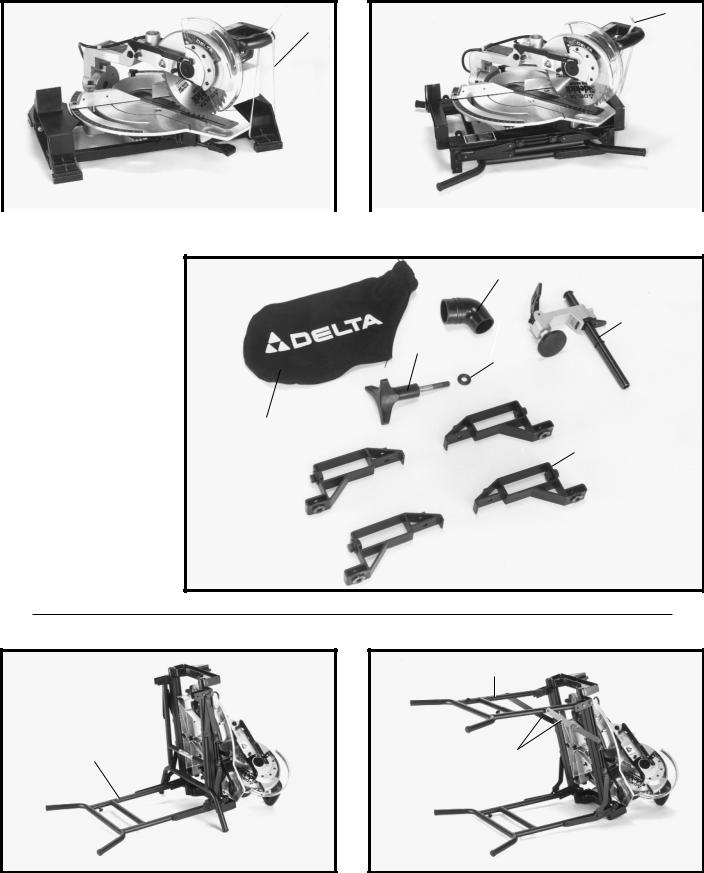
A
A
BENCH MODEL |
|
STAND MODEL |
Fig. 2 |
|
Fig. 3 |
CAUTION: DO NOT LIFT THE MACHINE BY THE OPERATING HANDLE.
1
2
1. |
Dust elbow |
3 |
|
|
|
2. |
Work clamp |
4 |
3. |
Bevel locking knob |
|
4. |
Flat washer |
5 |
|
|
|
5. |
Dust bag |
6 |
6.Four mounting feet (furnished with stand models only)
Fig. 4
ASSEMBLY
B
A |
C |
Fig. 5 |
Fig. 6 |
SETTING UP STAND (For Model 36-250 Only)
1.Tilt the machine on its right side and unfold right leg (A) as shown in Fig. 5.
2.Lift up and unfold left leg (B) Fig. 6, and lock in place by pushing inward on leg hinges (C).
6

3. Pivot the machine so feet (D) Fig. 7, of the left leg are on the floor. NOTE: Make certain the leg hinges (C) Fig. 7, are locked in place before raising the machine to an upright position.
4. Raise the right side of the machine and unfold right leg (A) Fig. 8. Lock right leg (A) in position by pushing hinges (E) inward.
5.Loosen four lock knobs on leg assemblies, two of which are shown at (F) Fig. 8.
6.With foot on lower brace (G) Fig. 9, lift up table extension (H) so upper leg (J) extends out from lower leg
(K) and protrusions (L) Fig. 10, snap in and engage with round holes in upper legs (J). This locks the upper and lower legs (J) and (K) in position. Tighten two locking knobs (F) Fig. 10.
7.Pull right side upper leg (L) Fig. 11, from lower leg (K) in the same manner. Tighten the remaining two locking knobs (F). CAUTION: Make certain both legs are fully extended and locked in position before operating the saw.
|
J |
|
|
|
J |
F |
L |
|
|
|
|
K |
F |
K |
|
Fig. 10
B
C
D
Fig. 7
E A
F
F
Fig. 8
H
J
K
G
Fig. 9
L
K
F
Fig. 11
7

MOVING CUTTINGHEAD TO THE REAR POSITION
(For models 36-240 and 36-250)
1.MAKE CERTAIN THE TOOL IS DISCONNECTED FROM THE POWER SOURCE.
2.Carefully remove cable tie (A) Fig. 12, which is holding the cuttinghead in the down position.
3. Find the bevel locking knob with flat washer (B) Fig. 13, supplied with the machine. Thread bevel locking knob and flat washer into hole (C) Fig. 13. Assembled bevel locking knob is shown in (B) Fig. 14. Firmly tighten locking knob.
4.To move the cuttinghead (D) Fig. 15, to the rear position, loosen lock knob (E) and push cuttinghead (D) to the rear position.Then tighten lock knob (E) Fig. 16.
5.Fig. 16, illustrates the cuttinghead locked in the rear position.
E
D
Fig. 15
A
Fig. 12
C
B
Fig. 13
B
Fig. 14
E
Fig. 16
8

A
B
Fig. 17
RAISING THE
CUTTINGHEAD
1.While holding the cuttinghead (A) Fig. 17, down, pull out and rotate cuttinghead lock knob (B) 90 degrees until pin (C) Fig. 18, is in the horizontal position as shown. The cuttinghead can then be raised.
2.Fig. 19, illustrates the cuttinghead (A) in the raised position.
ASSEMBLING DUST ELBOW AND DUST BAG
1. Insert smooth end of dust elbow (A) Fig. 20, into opening (B). The dust elbow (A) can be rotated as desired.
2. Compress spring clips (C) Fig. 21, on dust bag (D) and clip dust bag onto end of elbow (A) as shown.
C 
B
Fig. 18
A
Fig. 19
A
B
Fig. 20
D C
A
Fig. 21
9

MOVING TABLE TO THE 90 DEGREE CUT-OFF POSITION
1. Compress table locking lever (A) Fig. 22, and rotate table (B) to the straight 90 degree cut-off position. Release locking lever (A).
2.Fig. 23, illustrates the table (B) locked in the straight
90degree cut-off position. NOTE: Table locking lever (A) must be compressed when rotating table. When releasing lever (A) Fig. 23, the table is in the locked position.
3.For proper operation and adjustment of the table, refer to sections “ROTATING TABLE FOR MITER CUTTING”, “ADJUSTING CLAMPING ACTION OF
TABLE LOCKING MECHANISM” and “ADJUSTING
SLIDING FIT BETWEEN MOVABLE TABLE AND BASE.”
ASSEMBLING
WORK CLAMP
1.Insert post (A) Fig. 24, of work clamp assembly (B) down through hole in the base of the machine as shown and lock in place by tightening lock knob (C). The work clamp (B) Fig. 24, can be used on the right or left side of the cuttinghead.
2.For proper operation of the work clamp, refer to section “WORK CLAMP OPERATION.”
A
B
Fig. 22
A B
B
Fig. 23
B
A
C
Fig. 24
10
 Loading...