


Universal Miter Saw/Planer Stand
(Model 36-136)
INSTRUCTIVO DE OPERACIÓN,
CENTROS DE SERVICIO Y PÓLIZA
DE GARANTÍA. 
LÉASE ESTE INSTRUCTIVO ANTES |
PART NO. 657645-00 - 10-27-07 |
DE USAR EL PRODUCTO. |
Copyright © 2005, 2007 Delta Machinery |
To learn more about DELTA MACHINERY |
ESPAÑOL: PÁGINA 9 |
visit our website at: www.deltaportercable.com. |
FRANÇAISE : PAGE 17 |
For Parts, Service, Warranty or other Assistance, |
|
|
please call 1-800-223-7278 (In Canada call 1-800-463-3582).
INSTRUCTION
safety guidelines - definitions
This manual contains information that is important for you to know and understand. This information relates to protecting YOUR SAFETY and PREVENTING EQUIPMENT PROBLEMS. To help you recognize this information, we use the symbols below. Please read the manual and pay attention to these sections.
Indicates an imminently hazardous situation which, if not avoided, will result in death or serious injury.
Indicates a potentially hazardous situation which, if not avoided, could result in death or serious injury.
Indicates a potentially hazardous situation which, if not avoided, may result in minor or moderate injury.
Used without the safety alert symbol indicates potentially hazardous situation which, if not avoided, may result in property damage.
SAFETY RULES
READ AND UNDERSTAND ALL WARNINGS AND OPERATING INSTRUCTIONS BEFORE USING THIS EQUIPMENT. Failure to follow all instructions listed below, may result in electric shock, fire, and/or serious personal injury or property damage.
SAVE THESE INSTRUCTIONS
This product was designed for certain applications only. Delta Machinery strongly recommends that this product not be modified and/or used for any application other than that for which it was designed. If you have any questions relative to a particular application, DO NOT use this unit until you have first contacted Delta to determine if it can or
should be performed on the product.
Technical Service Manager Delta Machinery
4825 Highway 45 North Jackson, TN 38305
(IN CANADA: 125 Mural St. Suite 300, Richmond Hill, ON, L4B 1M4)
Failure to follow these rules may result in serious personal injury.
1.This product was designed to be used as a stand for miter saws and planers. The stand will support 300 lbs. Any misuse or abuse can result in product damage or personal injury.
2.DO NOT STAND ON THE WORK TABLE or use the support extensions as a ladder or scaffolding.
3.Properly secure the miter saw or planer to the stand before operation.
4.place the stand on a flat and level surface to prevent rocking or tipping.
5.take care during the raising and lowering of the product to reduce the hazard of pinching hands and fingers.
To reduce the risk of injury, keep both hands on handle when raising and lowering the stand. The stand has gas assist lifting and may
raise unexpectedly when lever is released.
6.Check the legs and other supports to see that they are properly locked in place before operation.
7.WEAR EYE AND HEARING PROTECTION. ALWAYS USE SAFETY GLASSES. Everyday eyeglasses are NOT safety glasses. USE CERTIFIED SAFETY EQUIPMENT. Eye protection equipment should comply with ANSI Z87.1 standards. Hearing equipment should comply with ANSI S3.19 standards.
8.DO NOT MODIFY or use the stand for any operation for which it is not intended.
FUNCTIONAL DESCRIPTION
FOREWORD
The Model 36-136 is a stand designed to accommodate most miter saws and planers and to provide portability for those units, both in the field and in the shop.
UNPACKING AND CLEANING
Carefully unpack the product and all loose items from the shipping container(s). Lay the parts down on the floor so that all parts will be easily accessible during assembly.
2

CARTON CONTENTS
1
4 |
4 |
2 |
3 |
1.Stand
2.Leg Extension
3.Storage Foot
4.Wheel/Storage Foot Connector (L & R)
5.Extension Roller (2)
6.Handle
7.Wheel (2)
8.Axle (2)
9.Adjustable Extension Fence (2)
10.Cord Wrap Brackets (2)
11.M8 x 15 mm Buttonhead Screw (6)
12.M8 x 25 mm Buttonhead Screw (2)
13.Attachment Bolt Assembly (4)
14.Roller Extension End Cap (4)
15.Curved Washer (6)
16.Flat Washer (2)
17.Extension Locking Knob (2)
18.Roller Extension Locking Knob (2)
19.M8 Lockwasher (2)
5
8
6
7
|
18 |
|
9 |
13 |
10 |
|
|
17 |
|
|
|
|
|
|
|
|
14 |
|
12 |
11 |
|
|
15 |
|
|
||
|
16 |
|
|
|
||
19 |
|
|
|
|
||
|
|
|
|
|
||
|
|
|
|
|
|
assembly
PINCH HAZARD. Do not attempt to raise or lower stand during assembly. There is a risk of a finger pinch hazard.
attaching the LEG EXTENSION
Place the stand on a table or the floor, upside down.
1.Insert the Leg extension (A) Fig. 1 in the stand (B).
2.Align the holes and install two M8 x 15 mm buttonhead screws with curved washers (C).
3.Tighten securely with the supplied hex wrench.
NOTE: The supplied hex wrench comes in the wrench storage, located in the corner of the stand, directly above one of the wheels (See Fig. 9).
attaching the wheel and STORAGE FOOT connector
1.Insert the wheel/storage-foot connector (A) Fig. 2 to the stand (B). Place it so that the wheel extension (C) faces outward.
2.Align the holes and loosely install two M8 x 15 mm buttonhead screws with curved washers (D) for further adjustment.
3.Attach the other connector in the same manner.
|
|
|
|
|
|
|
|
|
|
|
|
|
|
|
|
|
|
|
|
|
|
A |
|
|
|
|
|
|
|
|
|
|
|
||||||
|
|
|
|
|
|
B |
|
|
|
|
|
|
|
|
|
|
A |
|
|
|
|
|
|
|
|
|
|
|
|
|
|
|
|
|
|
|
|
|
|
|
|
|
|
|
|
|
|
|
|
|
|
|
|
|
|
|
|||
|
|
|
|
|
|
|
|
|
|
|
|
|
D |
||||||
|
|
|
|
|
|
|
|
|
|
|
|
|
|
|
|
C |
|||
|
|
|
|
|
C |
|
|
|
|
|
|
||||||||
|
|
|
|
|
|
|
|
|
|
B |
|
|
|
|
|
||||
|
|
|
|
|
|
|
|
|
|
|
|
|
|
|
|
||||
|
|
|
|
|
|
|
|
|
|
|
|
|
|
|
|
|
|
|
|
|
|
|
|
|
|
|
|
|
|
|
|
|
|
|
|
|
|
|
|
|
|
|
|
|
|
|
|
|
|
|
|
|
|
|
Fig. 2 |
|
|||
|
|
Fig. 1 |
|
|
|
|
|
|
|
|
|||||||||
|
|
|
|
|
|
|
|
|
|
|
|
|
|
|
|
|
|
|
|
|
|
|
|
|
|
|
|
|
|
|
|
|
|
|
|
|
|
|
|
3
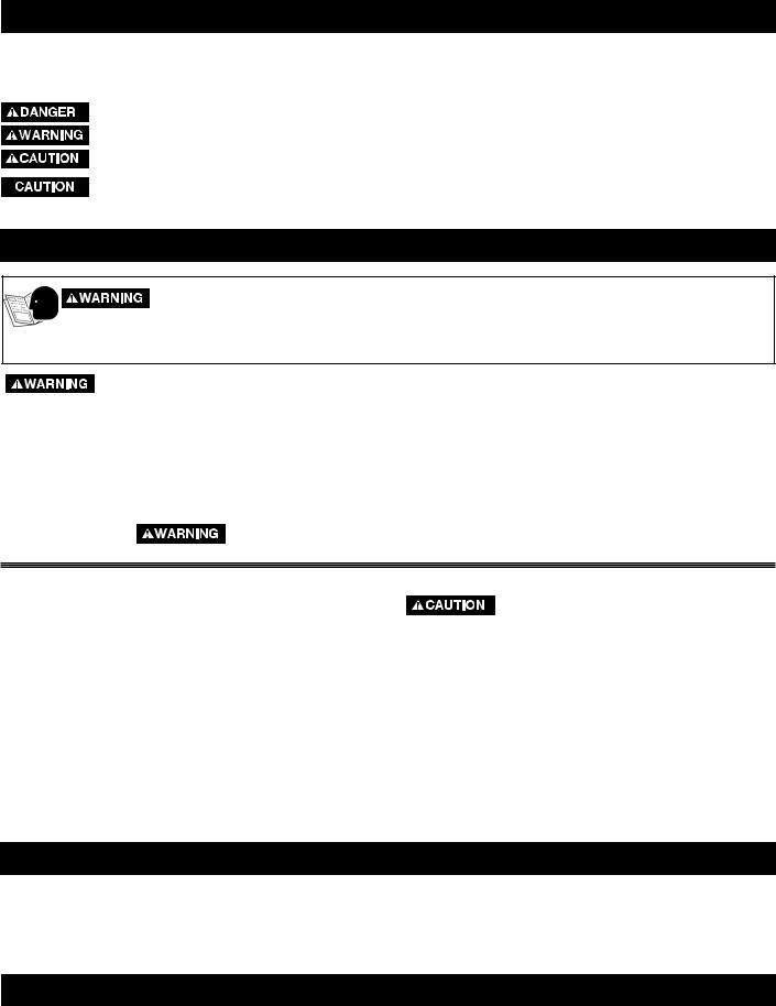
attaching the wheelS
1.Insert the axle (A) Fig. 3 from the inside of the wheel/storage-foot connector
2.Place one of the wheels on the axle with the longer side of the wheel hub facing inward.
3.Place the washer (B) on the axle and attach the nut (C). Tighten the nut.
NOTE: Do not overtighten. Wheel rotation can be impaired.
4.Attach the other wheel in the same manner.
attaching the STORAGE FOOT
1.Place the storage foot (A) Fig. 4 over the indentions of the wheel and storage-foot connector (B) so that, when the stand is upright, the storage foot will angle upward.
2.Align the holes and install two M8 x 15 mm buttonhead screws with the curved washers (C).
3.Tighten securely with the supplied hex wrench.
4.Securely tighten the storage-foot connector screws that were loosely tightened in STEP 3 of "ATTACHING THE WHEEL
AND STORAGE FOOT CONNECTOR".
A |
B C |
|
|
|
B |
|
|
A |
|
|
C |
|
Fig. 3 |
Fig. 4 |
attaching the EXTENSION ROLLERS
Turn the stand right side up.
1.Remove the foam plugs from the four extension holes.
2.Install an extension roller (A) Fig. 5 in the holes (B).
3.Install one of the longer lock-knobs with a flat washer
(C)Fig. 5. This lock-knob will lock the vertical movement of the extension roller.
4.Insert an extension roller end cap (D) in the bottom of both legs of the extension roller (A) and tap it in with a rubber mallet. Ensure that the tabs on the end caps are aligned with the holes in the legs.
5.Install the other extension roller in the same manner. NOTE: Raise the extension roller above the handle so that the extension can clear the handle.
|
A |
|
B |
C |
|
D |
Fig. 5 |
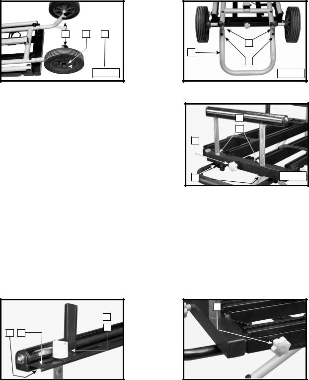
attaching the ADJUSTABLE EXTENSION FENCE
1.Insert the square nut (supplied with the extension fence) in the opening (A) Fig. 6 of the extension roller shelf (B).
2.Place the extension fence (C) on top of the shelf (B) and align the hole in the fence with the hole in the square nut.
3.Insert the lock-knob (D) through the fence (C) and the shelf (B) and into the square nut.
4.Tighten securely.
NOTE: The fence can turn in either direction depending on your application. Toward you, the fence becomes an extension of the saw fence. Facing away from you, the fence can work as a guide.
attaching the HORIZONTAL LOCK KNOBS
Install the two shorter lock-knobs (one shown at (A) Fig. 7) in the holes located on the front and rear of both sides of the stand. These lock-knobs lock the movement of the extension rollers.
A

 C
C
D
A B
Fig. 6 |
|
Fig. 7 |
|
|
|
4

attaching the HANDLE
1.Attach the handle (A) Fig. 8 to the end of the stand opposite the wheels with the two M8 x 25 mm buttonhead screws (B) and lockwashers from the inside.
2.Tighten securely with the supplied hex wrench.
WRENCH STORAGE
The supplied hex wrench (A) Fig. 9 comes in the wrench storage, located in the corner of the stand, directly above one of the wheels
A |
A |

 B
B
Fig. 8 |
|
Fig. 9 |
|
|
|
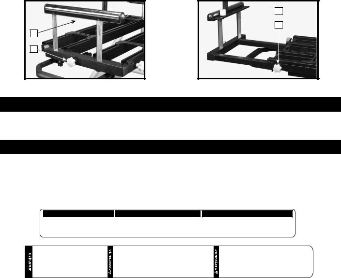
attaching the cord wraps
1.Use the supplied hex wrench to loosen the screws (A) Fig. 10 of the moveable saw connector (B).
2.Slide the moveable saw connector (C) Fig. 10B out of the shelf.
3.Slide the cord wraps (E) Fig. 10B on the shelf (D). Place the cord wraps in opposite positions (Fig. 10B) to hold the cord securely.
4.Place the cord wraps inside the moveable cord connectors and use the supplied hex wrench to tighten them securely.
5.Replace the saw connector (D) Fig. 10B in the shelf (F) Fig. 11 back in its original position.
6.Use the supplied hex wrench to tighten the screws securely.
|
C |
|
|
|
|
|
G |
B |
|
|
|
A |
|
E |
|
|
|
F |
|
|
|
|
|
Fig. 10 |
D |
Fig. 10B |
Fig. 11 |
|
attaching the TOOL
 Refer to your tool manufacturer’s instructions regarding the securing of your miter saw or planer to a stand or supporting surface. Secure the tool according to both the instructions in this manual and those in your tool manufacturer’s manual before operating.
1.Loosen (but do not remove) the hex nuts on each of the moveable connector bases (A) Fig. 12.
2.Place the miter saw or planer on the stand on top of the moveable connector bases. Align the holes of the tool and of the connectors and insert the attachment bolts from the bottom. Attach the washer, then the lock washer, then the wing nut.
3.Center your tool, both forward and backward and side to side, on the stand.
4.Securely tighten the wing nuts (A) Fig. 13 and the hex nuts on the connectors (A) Fig. 12.
NOTE: The attachment bolts included with this unit (two are shown at (A) Fig. 13) are designed to work with the larger miter saws, and may interfere with the operation of your tool. If so, purchase a shorter bolt of the same size for your unit.
NOTE: For tools that do not fit on the connectors, mount the tool on a piece of 3/4" or thicker plywood, then mount the plywood to the stand. To allow the plywood to sit flush on the supporting surface, be certain that the mounting screws do not go all the way through the plywood. When you use this method, place the clamps only where the mounting screw holes are located. Any other locations will interfere with the proper operation of the tool.
To prevent binding and/or inaccuracy, be sure that the mounting surface is not warped or uneven. If the tool rocks on the mounting surface, place a small piece of material under one of the tool feet to make the tool sit firmly on the mounting surface.
5

A |
Fig. 12 |

 A
A 

Fig. 13 |
|
Fig. 14 |
PRODUCT STABILITY TEST
The Universal Miter Saw/Planer stand is designed to be used in conjunction with a wide variety of miter saws, compound miter saws, sliding compound miter saws, and planers.
Any tool used with this stand must be properly positioned and secured to ensure stability and to prevent inadvertent tipping.
Mount your planer as shown in Fig. 14 to assure maximum stability.
To confirm the stability of your unit:
To reduce the risk of serious personal injury, turn tool off and disconnect tool from power source before installing and removing accessories, before adjusting or changing set-ups or when making repairs. An accidental start-up can cause injury.
Use two or more people to perform the stability test.
Raise the cuttinghead for all miter saws, compound miter saws, and sliding compound miter saws. Lock all sliding compound miter saws in the rear position.
1.Place a 2-1/2" thick block of wood (A) Fig. 15 under the front leg (B) of the stand so that the front leg is raised 2-1/2" off the floor.
2.With one person in front of the stand, and the other person behind, lift the front of the stand slightly, remove the block of wood, and allow the stand to fall forward.
Stay alert. The stand may tip during this procedure.
3.Perform this same test with the block of wood under the rear leg
(C)Fig. 15.
Stay alert. The stand may tip during this procedure.
B
A
C
Fig. 15
4.If the stand tends to tip to the front, reposition the tool toward the rear of the stand. If the stand tends to tip to the rear, reposition the tool forward. Make your adjustment, then repeat the test.
OPERATION
TO RAISE AND LOWER THE STAND
1.Place your right foot on the bottom of the extension leg (A) Fig. 16.
2.Grasp the handle (B) Fig. 16 with both hands.
3.Use the thumb of your left hand to push down on the red activating lever (C).
4.Lift up on the handle to release the safety mechanism, then raise or lower the stand. It will automatically lock into place.
B
C
A
Fig. 16
NOTE: The stand will adjust to two heights. Try both, select the one that fits you, and lock it in place.
NOTE: The stand has a gas-controlled cylinder that aids in raising the stand. To put the stand in the "down" position, push down on the red activating lever, lift up on the handle, then exert downward pressure on the handle.
To reduce the risk of injury, keep both hands on handle when raising and lowering the stand. The stand has gas assist lifting and may raise unexpectedly when lever is released.
6
TO EXTEND THE EXTENSION ROLLERS
1.Turn the horizontal extension lock knob (A) Fig. 18 counter-clockwise.
2.Move the extension roller (B) Fig. 18 out or in, depending on the length of the workpiece.
3.Tighten the horizontal extension lock knob.
TO RAISE AND LOWER THE EXTENSION ROLLERS
1.Turn the vertical extension lock knob (A) Fig. 17 counter-clockwise.
2.Raise or lower the extension roller (B) to match the height of the saw table.
3.Tighten the vertical extension lock knob.

 B
B
A
B
A
Fig. 17 |
|
Fig. 18 |
|
|
|
TROUBLESHOOTING
For assistance with your machine, visit our website at www.deltaportercable.com for a list of service centers or call the DELTA Machinery help line at 1-800-223-7278 (In Canada call 1-800-463-3582).
SERVICE
REPLACEMENT PARTS
Use only identical replacement parts. For a parts list or to order parts, visit our website at servicenet.deltamachinery.com. You can also order parts from your nearest factory-owned branch, or by calling our Customer Care Center at 1-800-223-7278 to receive personalized support from highly-trained technicians.
free warning label replacement
If your warning labels become illegible or are missing, call 1-800-223-7278 for a free replacement.
 CAUTION
KEEP BOTH HANDS ON HANDLE WHILE RAISING AND LOWERING STAND. STAND HAS GAS ASSIST LIFTING AND MAY RAISE UNEXPECTEDLY WHEN LEVER IS RELEASED.
 ATENCIÓN
MANTENGA AMBAS MANOS EN EL MANGO AL ELEVAR Y BAJAR LA BASE. LA BASE TIENE UN SISTEMA DE ELEVACIÓN ASISTIDA POR GAS Y PUEDE ELEVARSE EN FORMA INESPERADA AL SOLTAR LA PALANCA.
 ATTENTION
GARDER LES DEUX MAINS SUR LA POIGNÉE AU MOMENT DE RELEVER OU D'ABAISSER LE SOCLE. LE SOCLE EST DOTÉ D'UN DISPOSITIF DE LEVAGE AU GAZ QUI PEUT SE RELEVER SOUDAINEMENT LORSQUE LE LEVIER EST RELÂCHÉ.
FOR YOUR OWN SAFETY 1. READ AND UNDERSTAND INSTRUCTION MANUAL BEFORE USING. 2. This product is designed to be used for miter saws and planers. Any misuse or abuse can result in product damage or personal injury. 3. Do not stand on or use support extensions as ladder or scaffolding. (max load 300 lb.) 4. Make sure that tool is properly secured before operating. 5. Place on flat and level surface in order to limit product rocking or tipping. 6. Caution when using extensions. Always use handle to avoid pinch. 7. Open stand and make certain that latches are engaged, extension work supports are locked, and all knobs are tight before use.
POR SU PROPIA SEGURIDAD 1. LEA Y COMPRENDA EL MANUAL DE INSTRUCCIONES ANTES DE UTILIZAR EL PRODUCTO. 2. Este producto está diseñado para utilizarse con cepilladoras y sierras ingletadoras. Cualquier utilización indebida o abuso de este producto puede provocar daños en el mismo o lesiones personales. 3. No se pare sobre, ni utilice estructuras tales como escaleras o andamios. (carga máxima: 300 lbs.) 4. Verifique que la herramienta esté asegurada correctamente antes de operar la unidad. 5. Coloque la herramienta sobre una superficie plana y nivelada para evitar que oscile o se incline. 6. Tenga precaución al utilizar prolongaciones. Para evitar accidentes, utilice siempre el mango de la herramienta. 7. Abra la base y asegúrese de que los cerrojos estén colocados, los soportes de extensión trabados, y todas las perillas ajustadas antes de utilizar la herramienta.
POUR VOTRE PROPRE SÉCURITÉ 1. BIEN LIRE LE MODE D’EMPLOI AVANT D’UTILISER L’OUTIL. 2. Ce produit est conçu pour être utilisé avec des scies à onglets et des raboteuses. Toute mauvaise utilisation ou usage abusif peut endommager le produit ou causer des blessures. 3. Ne pas se tenir sur les extensions de support et ne pas les utiliser comme échelle ou échafaudage (poids maximal de 300 lb). 4. S’assurer que l’outil est bien fixé avant de l’utiliser. 5. Mettre le produit sur une surface plane à niveau afin d’éviter qu’il ne se balance ou ne bascule d’un côté. 6. Être prudent dans l'utilisation des extensions. Toujours utiliser la poignée pour éviter tout pincement. 7. Ouvrir le socle et s’assurer que les loquets sont engagés, que les supports de travail à extensions sont verrouillés et que les boutons sont serrés avant toute utilisation.
SERVICE AND REPAIRS
All quality tools will eventually require servicing and/or replacement of parts. For information about Delta Machinery, its factoryowned branches, or an Authorized Warranty Service Center, visit our website at www.deltaportercable.com or call our Customer Care Center at 1-800-223-7278. All repairs made by our service centers are fully guaranteed against defective material and workmanship. We cannot guarantee repairs made or attempted by others.
You can also write to us for information at Delta Machinery, 4825 Highway 45 North, Jackson, Tennessee 38305 - Attention: Product Service. Be sure to include all of the information shown on the nameplate of your tool (model number, type, serial number, etc.)
7

ACCESSORIES
A complete line of accessories is available from your Delta Supplier, Porter-Cable • Delta Factory Service Centers, and Delta Authorized Service Stations. Please visit our Web Site www.deltaportercable.com for a catalog or for the name of your nearest supplier.


 Since accessories other than those offered by Delta have not been tested with this product, use of such accessories could be hazardous. For safest operation, only Delta recommended accessories should be used with this product.
WARRANTY
To register your tool for warranty service visit our website at www.deltaportercable.com.
Two Year Limited New Product Warranty
Delta will repair or replace, at its expense and at its option, any new Delta machine, machine part, or machine accessory which in normal use has proven to be defective in workmanship or material, provided that the customer returns the product prepaid to a Delta factory service center or authorized service station with proof of purchase of the product within two years and provides Delta with reasonable opportunity to verify the alleged defect by inspection. For all refurbished Delta product, the warranty period is 180 days. Delta may require that electric motors be returned prepaid to a motor manufacturer’s authorized station for inspection and repair or replacement. Delta will not be responsible for any asserted defect which has resulted from normal wear, misuse, abuse or repair or alteration made or specifically authorized by anyone other than an authorized Delta service facility or representative. Under no circumstances will Delta be liable for incidental or consequential damages resulting from defective products. This warranty is Delta’s sole warranty and sets forth the customer’s exclusive remedy, with respect to defective products; all other warranties, express or implied, whether of merchantability, fitness for purpose, or otherwise, are expressly disclaimed by Delta.
LATIN AMERICA: This warranty does not apply to products sold in Latin America. For products sold in Latin America, see country specific warranty information contained in the packaging, call the local company or see website for warranty information.
8

La plate-forme universelle pour SCIES À ONGLETS ET POUR RABOTEUSES
(Modele 36-136)
PART NO. 657645-00 - 10-27-07
Copyright © 2007 Delta Machinery
Pour apprendre plus de la MACHINERIE DE DELTA |
|
|
|
ENGLISH: PÁGINA 1 |
|
visite notre site web à: www.deltaportercable.com. |
|
|
Pour les Parties, le Service, la Garantie ou l'autre Assistance, |
ESPANOL: PAGE 9 |
|
s'il vous plaît appeler 1-800-223-7278 |
9 |
|
(Dans l'appel de Canada 1-800-463-3582). |
|
|
L
INSTRUCTION
 Loading...