


MIDI-LATHE
Tour Midi-Lathe
Torno Midi
Français (37)
Español (72)
Instruction manual
Manuel d’utilisation
Manual de instrucciones
www.DeltaMachinery.com
INSTRUCTIVO DE OPERACIÓN, CENTROS DE SERVICIO
Y PÓLIZA DE GARANTÍA.  LÉASE ESTE
INSTRUCTIVO ANTES DE USAR EL PRODUCTO.
455
46-460

TABLE OF CONTENTS
IMPORTANT SAFETY INSTRUCTIONS..................... |
2 |
SAFETY GUIDELINES - DEFINITIONS...................... |
2 |
GENERAL SAFETY RULES....................................... |
3 |
ADDITIONAL SPECIFIC SAFETY RULES ................ |
4 |
FUNCTIONAL DESCRIPTION.................................... |
6 |
CARTON CONTENTS ................................................ |
6 |
ASSEMBLY................................................................. |
7 |
OPERATION................................................................ |
7 |
TROUBLESHOOTING................................................. |
15 |
MAINTENANCE........................................................... |
15 |
SERVICE..................................................................... |
17 |
ACCESSORIES........................................................... |
18 |
WARRANTY................................................................ |
18 |
FRANÇAIS................................................................... |
19 |
ESPAÑOL.................................................................... |
36 |
IMPORTANT SAFETY INSTRUCTIONS
Read all warnings and operating instructions before using any tool or equipment.
When using tools or equipment, basic safety precautions should always be followed to reduce the risk of personal injury. Improper operation, maintenance or modification of tools or equipment could result in serious
injury and property damage. There are certain applications for which tools and equipment are designed. DELTA® Power Equipment Corporation strongly recommends that this product NOT be modified and/or used for any application other than for which it was designed.
If you have any questions relative to its application DO NOT use the product until you have written DELTA® Power Equipment Corporation
and we have advised you. Contact us online at www.DeltaMachinery.com or by mail at Technical Service Manager, DELTA® Power Equipment Corporation, 99 Roush Street, Anderson, South Carolina 29625.
•Power Tool Institute, 1300 Sumner Avenue, Cleveland, OH 44115-2851or online at www.powertoolinstitute.com
•National Safety Council, 1121 Spring Lake Drive, Itasca, IL 60143-3201
•American National Standards Institute, 25 West 43rd Street, 4 floor, New York, NY 10036 www.ansi.org - ANSI 01.1 Safety Requirements for Woodworking Machines
•U.S. Department of Labor regulations www.osha.gov
SAVE THESE INSTRUCTIONS!
SAFETY GUIDELINES - DEFINITIONS
It is important for you to read and understand this manual. The information it contains relates to protecting YOUR SAFETY and PREVENTING PROBLEMS. The symbols below are used to help you recognize this information.
 indicates an imminently hazardous situation which, if not avoided, will result in death or serious injury.


 indicates a potentially hazardous situation which, if not avoided, could result in death or serious injury.


 indicates a potentially hazardous situation which, if not avoided, may result in minor or moderate injury. indicates a practice not related to personal injury which, if not avoided, may result in property damage.
 Some dust created by power sanding, sawing, grinding, drilling, and other construction activities contains chemicals known to the State of California to cause cancer, birth defects or other reproductive harm. Some examples of these chemicals are:
•lead from lead-based paints,
•crystalline silica from bricks and cement and other masonry products, and
•arsenic and chromium from chemically-treated lumber.
Your risk from these exposures varies, depending on how often you do this type of work. To reduce your exposure to these chemicals: work in a well ventilated area, and work with approved safety equipment, always wear NIOSH/OSHA approved, properly fitting face mask or respirator when using such tools.
2

GENERAL SAFETY RULES
 Failure to follow these rules may result in serious personal injury.
1.For your own safety, read the instruction manual before operating the machine. Learning the machine’s application, limitations, and specific hazards will greatly minimize the possibility of accidents and injury.
2.Wear eye and hearing protection and always use safety glasses. Everyday eyeglasses are not safety glasses. Use certified safety equipment. Eye protection equipment should comply with ANSI Z87.1 standards. Hearing equipment should comply with ANSI S3.19 standards.
3.Wear proper apparel. Do not wear loose clothing, gloves, neckties, rings, bracelets, or other jewelry which may get caught in moving parts. Nonslip protective footwear is recommended. Wear protective hair covering to contain long hair.
4.Do not use the machine in a dangerous environment.
The use of power tools in damp or wet locations or in rain can cause shock or electrocution. Keep your work area well-lit to prevent tripping or placing arms, hands, and fingers in danger.
5.Do not operate electric tools near flammable liquids or in gaseous or explosive atmospheres. Motors and switches in these tools may spark and ignite fumes.
6.Maintain all tools and machines in peak condition.
Keep tools sharp and clean for best and safest performance. Follow instructions for lubricating and changing accessories. Poorly maintained tools and machines can further damage the tool or machine and/or cause injury.
7.Check for damaged parts. Before using the machine, check for any damaged parts. Check for alignment of moving parts, binding of moving parts, breakage of parts, and any other conditions that may affect its operation. A guard or any other part that is damaged should be properly repaired or replaced with DELTA® or factory authorized replacement parts. Damaged parts can cause further damage to the machine and/or injury.
8.Keep the work area clean. Cluttered areas and benches invite accidents.
9.Keep children and visitors away. Your shop is a potentially dangerous environment. Children and visitors can be injured.
10.Reduce the risk of unintentional starting. Make sure that the switch is in the “OFF” position before plugging in the power cord. In the event of a power failure, move the switch to the “OFF” position. An accidental start-up can cause injury. Do not touch the plug’s metal prongs when unplugging or plugging in the cord.
11.Use the guards. Check to see that all safety devices are in place, secured, and working correctly to prevent injury.
12.Remove adjusting keys and wrenches before starting the machine. Tools, scrap pieces, and other debris can be thrown at high speed, causing injury.
13.Use the right machine. Don’t force a machine or an attachment to do a job for which it was not designed. Damage to the machine and/or injury may result.
14.Use recommended accessories. The use of accessories and attachments not recommended by DELTA® may cause damage to the machine or injury to the user.
15.Use the proper extension cord. Make sure your extension cord is in good condition. When using an extension cord, be sure to use one heavy enough to carry the current your product will draw. An undersized cord will cause a drop in line voltage, resulting in loss of power and overheating. See the Extension Cord Chart for the correct size depending on the cord length and nameplate ampere rating. If in doubt, use the next heavier gauge. The smaller the gauge number, the heavier the cord.
16.Secure the workpiece. Use clamps or a vise to hold the workpiece when practical. Loss of control of a workpiece can cause injury.
17.Feed the workpiece against the direction of the rotation of the blade, cutter, or abrasive surface.
Feeding it from the other direction will cause the workpiece to be thrown out at high speed.
18.Don’t force the workpiece on the machine. Damage to the machine and/or injury may result.
19.Don’t overreach. Loss of balance can make you fall into a working machine, causing injury.
20.Never stand on the machine. Injury could occur if the tool tips, or if you accidentally contact the cutting tool.
21.Never leave the machine running unattended. Turn the power off. Don’t leave the machine until it comes to a complete stop. A child or visitor could be injured.
22.Turn the machine “OFF”, and disconnect the machine from the power source before installing or removing accessories, changing cutters, adjusting or changing set-ups. When making repairs, be sure to lock the start switch in the “OFF” position. An accidental start-up can cause injury.
23.Make your workshop childproof with padlocks, master switches, or by removing starter keys. The accidental start-up of a machine by a child or visitor could cause injury.
24.Stay alert, watch what you are doing, and use common sense. Do not use the machine when you are tired or under the influence of drugs, alcohol, or medication. A moment of inattention while operating power tools may result in injury.
25. Use of this tool can generate and disperse dust or other airborne particles, including wood dust, crystalline silica dust and asbestos dust.
Direct particles away from face and body. Always operate tool in well ventilated area and provide for proper dust removal. Use dust collection system wherever possible. Exposure to the dust may cause serious and permanent respiratory or other injury, including silicosis (a serious lung disease), cancer, and death. Avoid breathing the dust, and avoid prolonged contact with dust. Allowing dust to get into your mouth or eyes, or lay on your skin may promote absorption of harmful material. Always use properly fitting NIOSH/OSHA approved respiratory protection appropriate for the dust exposure, and wash exposed areas with soap and water.
3

ADDITIONAL SPECIFIC SAFETY RULES
 Failure to follow these rules may result in serious personal injury.
1. DO NOT OPERATE THIS MACHINE UNTIL it is assembled and installed according to the instructions.
2.OBTAIN ADVICE from your supervisor, instructor, or another qualified person if you are not familiar with the operation of this machine.
3.FOLLOW ALL WIRING CODES and recommended electrical connections.
4.ROUGH CUT THE WORKPIECE as close as possible to the finished shape before installing it on the faceplate.
5.EXAMINE THE WORKPIECE FOR FLAWS and test glue joints before mounting the workpiece on machine. DO NOT mount a split workpiece or one containing a knot.
6.SECURELY FASTEN THE WORKPIECE to the faceplate prior to faceplate turning. Use the appropriate size faceplate to properly support the workpiece. Do not let the screw fasteners interfere with the turning tool at the finished dimension of the workpiece.
7.NEVER DRIVE THE WORKPIECE into the drive center while the drive center is in the headstock. Set the drive center into the workpiece with a soft mallet prior to installing it on the headstock.
8.SNUG THE TAILSTOCK CENTER against the workpiece and lock it. Lubricate the tailstock center if it is not a ball bearing center.
9.PROPERLY ADJUST THE TOOL REST HEIGHT.
10.ADJUST THE TOOL REST so it is as close to the workpiece as possible.
11.TIGHTEN ALL CLAMP LOCKING HANDLES before operating.
12.ROTATE THE WORKPIECE BY HAND to check clearance before turning the machine “ON”.
13.CLEAR THE LATHE BED OF ALL OBJECTS (tools, scraps of wood, etc.) before turning the machine “ON”.
14.EXAMINE THE SET-UP CAREFULLY before turning the machine “ON”.
15.STAND CLEAR, AND KEEP ALL OBSERVERS AND PASSERSBY clear of rotating path of workpiece to avoid injury from flying debris.
16.USE THE LOWEST SPEED when starting a new workpiece. NEVER EXCEED recommended speeds.
17.NEVER ADJUST THE TOOL REST while the workpiece is turning.
18.NEVER LOOSEN THE TAILSTOCK SPINDLE or the tailstock while workpiece is turning.
19.MOVE THE CUTTING TOOL INTO THE WORKPIECE SLOWLY, and cut small amounts when roughing.
20.REMOVE THE TOOL REST before sanding or polishing.
21.NEVER PERFORM LAYOUT, assembly, or set-up work on the table/work area when the machine is running.
22.TURN THE MACHINE “OFF” AND DISCONNECT THE MACHINE from the power source before installing or removing accessories, before adjusting or changing set-ups, or when making repairs.
23.TURN THE MACHINE “OFF”, disconnect the machine from the power source, and clean the table/work area before leaving the machine. LOCK THE SWITCH IN THE “OFF” POSITION to prevent unauthorized use.
24.TIGHTEN ALL SCREWS AND LEVERS SECURELY when adjusting any part of the lathe. Also, be sure any lathe accessories are fastened and tightened before turning on the lathe.
25.WHEN USING THE INCLUDED 3" (76 MM) FACEPLATE, DO NOT MOUNT PIECES LARGER THAN 6” (152 MM) IN DIAMETER and up to 6" (152
mm)in length. For mounting larger pieces, be sure to use an appropriately sized faceplate.
26.KEEP HANDS OFF WORKPIECE when it is spinning.
27.USE ONLY ACCESSORIES RECOMMENDED FOR THIS PRODUCT and follow all instructions included with the accessories.
28.BE SURE CORD IS NOT IN THE WAY of the spinning workpiece or spinning lathe parts.
29.DO NOT TOUCH THE TIP OF YOUR TURNING TOOL directly after it has been used on the workpiece as it may be hot.
30.DO NOT APPLY WATER OR OTHER COOLANTS TO LATHE when it is spinning.
31.DO NOT TURN MATERIALS OTHER THAN WOOD ON THIS LATHE. This lathe was designed for wood turning only.
32.BE SURE ANY CHUCK KEYS OR WRENCHES ARE OUT OF THE CHUCK before operating the lathe.
33.FOR THE DELTA® MODEL 46-460 MIDI-LATHE ONLY: Be sure to only use accessories equipped with locking set screws for turning the lathe in reverse. Also, do not switch lathe turning directions until the workpiece comes to a complete stop.
34.ADDITIONAL INFORMATION regarding the safe and proper operation of power tools (i.e. a safety video) is available from the Power Tool Institute, 1300 Sumner Avenue, Cleveland, OH 44115-2851 (www. powertoolinstitute.com). Information is also available from the National Safety Council, 1121 Spring Lake Drive, Itasca, IL 60143-3201. Please refer to the American National Standards Institute ANSI 01.1 Safety Requirements for Woodworking Machines and the U.S. Department of Labor OSHA 1910.213 Regulations.
SAVE THESE INSTRUCTIONS!
4

POWER CONNECTIONS
A separate electrical circuit should be used for your machines. This circuit should not be less than #12 wire and should be protected with a time delay fuse. NOTE: Time delay fuses should be marked “D” in Canada and “T” in the US. If an extension cord is used, use only 3-wire extension cords which have 3-prong grounding type plugs and matching receptacle which will accept the machine’s plug. Before connecting the machine to the power line, make sure the switch (s) is in the “OFF” position and be sure that the electric current is of the same characteristics as indicated on the machine. All line connections should make good contact. Running on low voltage will damage the machine.
To reduce the risk of injury, do not expose the machine to rain or operate the machine in damp locations.
MOTOR SPECIFICATIONS
Your machine is wired for 120 volt, 60 HZ alternating current. Before connecting the machine to the power source, make sure the switch is in the “OFF” position.
GROUNDING INSTRUCTIONS
 This machine must be grounded while in use to protect the operator from electric shock.
1.All grounded, cord-connected machines:
In the event of a malfunction or breakdown, grounding provides a path of least resistance for electric current to reduce the risk of electric shock. This machine is equipped with an electric cord having an equipment-grounding conductor and a grounding plug. The plug must be plugged into a matching outlet that is properly installed and grounded in accordance with all local codes and ordinances.
Do not modify the plug provided - if it will not fit the outlet, have the proper outlet installed by a qualified electrician.
Improper connection of the equipment-grounding conductor can result in risk of electric shock. The conductor with insulation having an outer surface that is green with or without yellow stripes is the equipment-grounding conductor. If repair or replacement of the electric cord or plug is necessary, do not connect the equipment-grounding conductor to a live terminal.
Check with a qualified electrician or service personnel if the grounding instruction are not completely understood, or if in doubt as to whether the machine is properly grounded.
Use only 3-wire extension cords that have 3-prong grounding type plugs and matching 3-conductor receptacles that accept the machine’s plug, as shown in Fig. A.
Repair or replace damaged or worn cord immediately.
2.Grounded, cord-connected machines intended for use on a supply circuit having a nominal rating less than 150 volts:
If the machine is intended for use on a circuit that has an outlet that looks like the one illustrated in Fig. A, the machine will have a grounding plug that looks like the plug illustrated in Fig. A. A temporary adapter, which looks like the adapter illustrated in Fig. B may be used to connect this plug to a matching 2-conductor receptacle as shown in Fig. B, if a properly grounded outlet is not available. The temporary adapter should be used only until a properly grounded outlet can be installed by a qualified electrician. The green-colored rigid ear, lug, and the like, extending from the adapter must be connected to a permanent ground such as a properly grounded outlet box. Whenever the adapter is used, it must be held in place with a metal screw.
NOTE: In Canada, the use of a temporary adapter is not permitted by the Canadian Electric Code.
In all cases, make certain that the receptacle in question is properly grounded. If you are not sure, have a qualified electrician check the receptacle.
|
GROUNDED OUTLET BOX |
|
GROUNDED OUTLET BOX |
|
|
CURRENT |
GROUNDING MEANS |
|
|
|
|
CARRYING |
|
|
|
ADAPTER |
|
PRONGS |
|
|
|
|
|
|
|
|
GROUNDING BLADE
IS LONGEST OF THE 3 BLADES
Fig. A |
Fig. B |
5

EXTENSION CORDS


 Use proper extension cords. Make sure your extension cord is in good condition and is a 3-wire extension cord which has a 3-prong grounding type plug and matching receptacle which will accept the machine’s plug. When using an extension cord, be sure to use one heavy enough to carry the current of the machine. An undersized cord will cause a drop in line voltage, resulting in loss of power and overheating. Fig. D-1 shows the correct gauge to use depending on the cord length. If in doubt, use the next heavier gauge. The smaller the gauge number, the heavier the cord.
MINIMUM GAUGE EXTENSION CORD
RECOMMENDED SIZES FOR USE WITH STATIONARY ELECTRIC MACHINES
|
|
Total |
|
Ampere |
|
Length of |
|
|
Cord in |
Gauge of Extension |
|
|
|
||
Rating |
Volts |
Feet |
Cord |
0-6 |
120 |
up to 25 |
18 AWG |
0-6 |
120 |
25-50 |
16 AWG |
0-6 |
120 |
50-100 |
16 AWG |
0-6 |
120 |
100-150 |
14 AWG |
6-10 |
120 |
up to 25 |
18 AWG |
6-10 |
120 |
25-50 |
16 AWG |
6-10 |
120 |
50-100 |
14 AWG |
6-10 |
120 |
100-150 |
12 AWG |
10-12 |
120 |
up to 25 |
16 AWG |
10-12 |
120 |
25-50 |
16 AWG |
10-12 |
120 |
50-100 |
14 AWG |
10-12 |
120 |
100-150 |
12 AWG |
12-16 |
120 |
up to 25 |
14 AWG |
12-16 |
120 |
25-50 |
12 AWG |
12-16 |
120 |
GREATER THAN 50 FEET NOT RECOMMENDED |
|
Fig. D-1
FUNCTIONAL DESCRIPTION
FOREWORD
DELTA® Midi-Lathe 46-460: Electronic variable speed lathe with a 1 HP Max motor that can turn objects at any speed between 250 and 4,000 RPMs.
DELTA® Midi-Lathe 46-455: Manual 5-speed lathe with a 3/4 HP Max that can turn objects at five different speeds, from 500 RPM to 4,000 RPM.
Both lathes will turn objects up to 12-1/2" (318 mm) in diameter over the bed and 9" (229 mm) in diameter over the tool rest base. The maximum distance between centers is 16-1/2" (419 mm).
NOTICE: The manual cover illustrates the current production model. All other illustrations contained in the manual are representative only and may not depict the actual labeling or accessories included. These are intended to illustrate technique only.
CARTON CONTENTS
A. |
Faceplate |
A |
|
|
|
|
|
D |
|
|
|||
B. |
Tailstock |
|
|
|
||
|
|
|
|
|
||
|
|
|
|
|
||
C. |
Tool rest base |
|
|
|
|
|
D. |
6 in. (152 mm) tool rest |
|
|
|
|
|
E. |
Hex wrench 3 mm |
|
|
|
|
|
|
|
|
|
B |
||
F. |
Live center |
|
|
|
|
|
G. |
Spur center |
|
|
|
|
|
H. |
Knockout bar |
|
|
|
|
|
I. |
Faceplate wrench |
|
|
|
|
|
J. |
10 in. (254 mm) tool rest |
|
|
|
|
|
C
J
|
|
|
|
|
|
|
|
|
|
|
|
|
|
|
G |
|
|
|
|
E |
|
|
|
|
|
|
|
|
|
|
|
|
|
|
|
|
|
|
|
|
|
|
|
|
|
|
|
I |
|
|
|
F |
|
|
|
H |
|
||
|
|
|
|
|
|
|
|||
|
|
|
|
|
|||||
6
UNPACKING AND CLEANING
Carefully unpack the machine and all loose items from the shipping container(s). Remove the rust-preventative oil from unpainted surfaces using a soft cloth moistened with mineral spirits, paint thinner or denatured alcohol.
To reduce the risk of injury, do not use highly volatile solvents such as gasoline, naphtha, acetone or lacquer thinner for cleaning your machine.
 To reduce the risk of injury, always use at least two people when lifting.
After cleaning, cover the unpainted surfaces with a good quality household floor paste wax.
ASSEMBLY
 To reduce the risk of injury, turn unit off and disconnect it from power source before installing and removing accessories, before adjusting or when making repairs. An accidental start-up can cause injury.
ASSEMBLY ITEMS REQUIRED
3/8" hex head screws for bolting lathe down (not supplied) Wrench for 3/8" hex head screws (not supplied)
ASSEMBLY TIME ESTIMATE
Assembly for this machine takes less than 30 minutes.
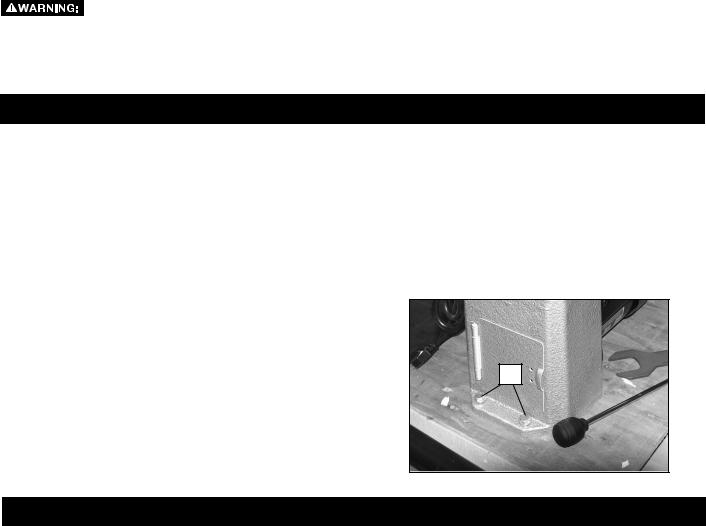
 To reduce the risk of injury, the lathe must be bolted to a secure work bench or other sturdy surface.
Bolt lathe down using four 3/8" hex head screws (not supplied) at the four holes in lathe base, two of which are shown at (K) Fig. 1.
K
Fig. 1
OPERATION
 To reduce the risk of injury:
•Turn unit off and disconnect it from power source before installing and removing accessories, before adjusting or when making repairs. An accidental start-up can cause injury.
•Tighten all screws and levers securely when adjusting any part of the lathe. Also, be sure any lathe accessories are fastened and tightened before turning on the lathe.
•When using the included 3" (76 mm) faceplate (B) Fig. 2, do not mount pieces larger than 6" (152 mm) in diameter and up to 6" (152 mm) in length. For mounting larger pieces, be sure to use an appropriately sized faceplate.
•Keep hands off workpiece when it is spinning.
•Use only accessories recommended for this product and follow all instructions included with the accessories.
•Be sure cord is not in the way of the spinning workpiece or spinning lathe parts.
•Do not touch the tip of your turning tool directly after it has been used on the workpiece as it may be hot.
•Do not apply water or other coolants to lathe when it is spinning.
• Do not turn materials other than wood on this lathe. This lathe was designed for turning wood only.
•Be sure any chuck keys or wrenches are out of the chuck before operating the lathe.
•FOR THE DELTA® MODEL 46-460 MIDI-LATHE ONLY: Be sure to only use accessories equipped with locking set screws for turning the lathe in reverse. Also, do not switch lathe turning directions until the workpiece comes to a complete stop.
7

FACEPLATE
 To reduce the risk of injury, tighten all screws and levers securely when adjusting any part of the lathe.
 To reduce the risk of injury, when using the included 3" (76 mm) faceplate (B) Fig. 2, do not mount
pieces larger than 6" (152 mm) in diameter and up to 6" (152 mm) in length. For mounting larger pieces, be sure to use an appropriately sized faceplate.
REMOVING FACEPLATE
To remove the faceplate, use the included 3 mm hex wrench to unlock the set screws (L) at least two full turns. Place knockout bar (H) Fig. 3 in hole (M) Fig. 2 and place faceplate wrench (I) Fig. 3 on faceplate shoulder flats (as shown in Fig. 3) and turn wrench to loosen faceplate. Once loose, the faceplate (B) Fig. 2 can be unscrewed.
REPLACING FACEPLATE
 FOR THE DELTA® MODEL 46-460 MIDILATHE ONLY: To reduce the risk of injury, if turning in reverse, be sure to tighten the set screws (L) Fig. 2 securely when replacing the faceplate.
To re-attach faceplate (B) Fig. 4, screw it back on to the spindle nose (K) and tighten securely using the knockout bar and wrench as shown in figure 3. Replace set screws
(L) Fig. 2 if removed. Tighten set screws securely.
Directions for mounting a workpiece to the faceplate can be found in the section Mounting the Workpiece under
MACHINE USE.
B
L
M
Fig. 2
H
I
Fig. 3
|
|
B |
K |
|
|
|
|
|
Fig. 4
8
SPUR AND LIVE CENTERS
 To reduce the risk of injury, tighten all screws and levers securely when adjusting any part of the lathe.
 To reduce the risk of injury, be sure the taper on the spur center (G) is clean before mounting to the headstock spindle.
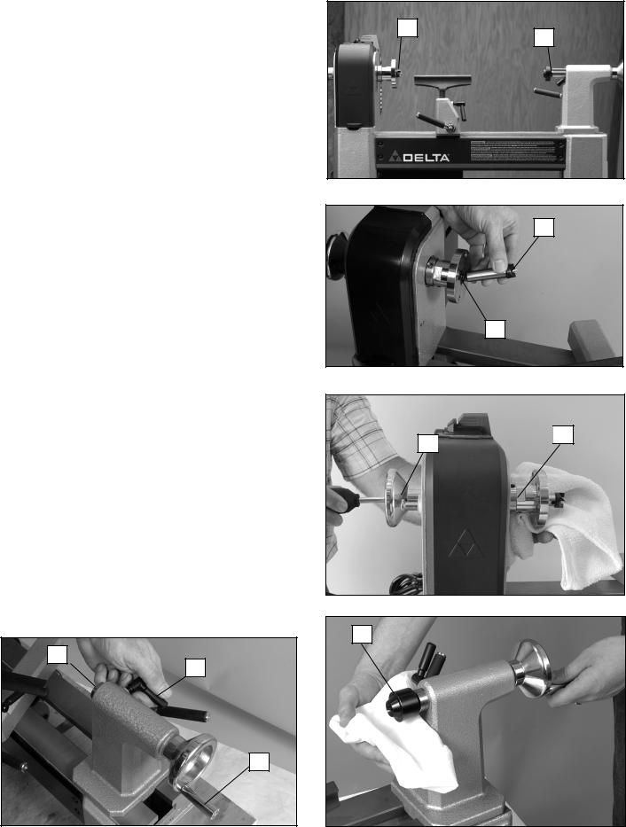
The spur center (G) Fig. 5 and live center (F) can be used together (as shown in Fig. 5) to turn workpieces up to 16-1/2" (419 mm) in length.
ATTACHING SPUR CENTER
Drive spur center into the workpiece using a soft mallet. Then fit spur center (G) Fig. 6 into the headstock spindle bore (N) snugly.
NOTE: You do not need to remove the faceplate to attach spur center.
REMOVING THE SPUR CENTER
 To reduce the risk of injury, when removing the centers, use a soft cloth to protect against the sharp edge.
Insert knockout bar (H) Fig. 7 into spindle bore (as shown in Fig. 7) and tap spur center (G) firmly to remove. If necessary, tap knockout bar firmly with soft mallet.
NOTE: To avoid damage to spur center, be sure to hold onto spur center as you tap it out.
ATTACHING LIVE CENTER
Loosen tailstock quill locking screw (O) Fig. 8. Turn tailstock crank (P) clockwise three full turns to advance the quill (Q). Then fit the live center (F) Fig. 9 into the quill snugly. The tailstock quill locking screw (O) Fig. 8 will be tightened after you mount the workpiece.
REMOVING THE LIVE CENTER
 To reduce the risk of injury, when removing the centers, use a soft cloth to protect against the sharp edge.
To eject the live center (F) Fig. 9, turn tailstock crank
(P) Fig. 8 counterclockwise to retract the quill. As quill retracts, the live center contacts an internal ejecting pin. When it does, you will feel the crank get harder to turn. Turning further past this point loosens the live center for easy removal.
Q
O
P
G
F
Fig. 5
G
H
Fig. 6
H 
 G
G
Fig. 7
F
Fig. 8 |
Fig. 9 |
9

TAILSTOCK
 To reduce the risk of injury, tighten all screws and levers securely when adjusting any part of the lathe.
ADJUSTING TAILSTOCK
To adjust the position of the tailstock (A), loosen tailstock locking lever (R) by lifting. Slide tailstock (A) along the bed (Fig. 11) into the desired location. Tighten tailstock locking lever (R) Fig. 10 by pressing downward to lock in place.
 To reduce the risk of injury, don’t position edge of tailstock (S) Fig. 11 beyond the edge of the lathe bed (T).
REMOVING TAILSTOCK
To remove the tailstock (A) Fig. 10, unlock the tailstock locking lever (R) and slide it off the end of the lathe bed.
LOCKING THE QUILL
The quill locking screw (O) Fig. 12 locks the quill (Q) in place when used with the supplied live center or other lathe accessories.
TAILSTOCK CRANK
The tailstock crank (P) advances and retracts the quill (Q).
TOOLREST
 To reduce the risk of injury, tighten all screws and levers securely when adjusting any part of the lathe.
To adjust the tool rest base (U) Fig. 13, loosen the tool rest base locking lever (V) and adjust. The tool rest base can be positioned side to side, forward and backwards or rotated as desired. Once in position, securely lock the base with the lever (V).
To adjust the tool rest (D), loosen the toolrest locking screw (W). The tool rest can be positioned as desired. Once in position, securely lock the tool rest with the lever
(V).
NOTE: if necessary, the spring-loaded locking screw handle (W) can be ratcheted to a more convenient position by pulling the handle outward.
R
A
Fig. 10
A
S T
Fig. 11
Q
O
P
Fig. 12
D |
W |
V |
U |
Fig. 13
10
CHANGING LATHE SPEEDS
 To reduce the risk of injury, do not operate lathe with pulley cover door open.
For the 46-455 lathe, the lathe speed is determined by one of five pulley sets (See Changing Pulleys section below.) The pulleys with the 46-455 lathe provide five different speed settings: 500, 950, 1550, 2700 and 4000 RPMs.
The 46-460 lathe is equipped with electronic variable speed control. Changing among the three pulley sets (see Changing Pulleys section below) determines the lathe's speed range and a control knob dials the speed up or down within that range. The pulleys with the 46-460 lathe provide three different speed ranges: 250-750 RPMs, 600-1800 RPMs and 1350-4000 RPMs.
CHANGING PULLEYS (46-455 and 46-460)  To reduce the risk of injury, do not operate lathe with pulley cover door open.
To move the belt between pulleys:
1.Lift up pulley cover (X) Fig. 14.
2.Pull down belt tensioning lever (Y) Fig. 15 to release belt tension.
3.Open lower side door (AA) Fig. 16 and move belt to desired pulley set according to the speed chart on inside of pulley cover (X) Fig. 14 NOTE: Be sure the grooves on the inside of the belt (BB) Fig. 17 fully engage the grooves (CC) on both pulleys and that the belt does not hang off the edge of the pulley.
4.Lift belt tensioning lever (Y) Fig. 15 up until it snaps into place.
5.Close both the lower side door (AA) Fig. 16 and the pulley cover (X) Fig. 14 securely.
To adjust belt tension:
SPEED RECOMMENDATIONS FOR MIDI LATHE
The following guidelines are approximate and must be reduced if the piece you are working on is out of balance. These speeds are only for side grain pieces. Reduce speed and take special care when cutting end grain.
RECOMMENDED SPEEDS (RPMs)
|
Roughing |
Finishing |
|||
|
|
|
|
|
|
Diameter of work |
Low |
|
High |
Low |
High |
|
|
|
|
|
|
Under 2 in. |
950 |
|
1500 |
1900 |
3000 |
(51 mm) |
|
||||
|
|
|
|
|
|
|
|
|
|
|
|
2 in. to 4 in. |
500 |
|
750 |
1500 |
2300 |
(51 mm to 107 mm) |
|
||||
|
|
|
|
|
|
|
|
|
|
|
|
4 in. to 6 in. |
500 |
|
750 |
1500 |
2300 |
(107 mm to 152 mm) |
|
||||
|
|
|
|
|
|
|
|
|
|
|
|
6 in. to 8 in. |
250 |
|
500 |
900 |
1500 |
(152 mm to 203 mm) |
|
||||
|
|
|
|
|
|
|
|
|
|
|
|
8 in. to 10 in. |
250 |
|
500 |
900 |
1500 |
(203 mm to 254 mm) |
|
||||
|
|
|
|
|
|
|
|
|
|
|
|
10 in. to 12 in. |
250 |
|
500 |
900 |
1500 |
(254 mm to 305 mm) |
|
||||
|
|
|
|
|
|
|
|
|
|
|
|
|
Fig. 18 |
|
|
|
|
X
Fig. 14
Y
Fig. 15
AA
Fig. 16
CC |
BB |
|
Fig. 17
11

NOTE: The belt tension is pre-set at the factory and should only require adjusting if the belt stretches over time or is replaced.
1.Open pulley cover (X) Fig. 14 and side door (AA) Fig. 16.
2.Pull down belt tensioning lever (Y) Fig. 15 to release belt tension. Do not lock it below the tab (Z).
3.Turn thumbwheel (DD) Fig. 19 clockwise to increase tension, or counterclockwise to decrease tension.
NOTE: A properly tensioned belt should deflect approximately 1/4" (6.4 mm) with moderate finger pressure.
4.Lift lever (Y) Fig. 15 and snap into place.
5.Close lower side door (AA) Fig. 16 and pulley cover
(X) Fig. 14 securely.
ELECTRONIC VARIABLE SPEED CONTROL (46-460 ONLY)
Once you select a speed range (as described above in Changing Pulleys section), use the speed control knob (EE) Fig. 20 to vary the speed within that range. As you face the lathe, turn knob forwards (towards you) to increase speed, turn it backwards (or away from you) to decrease speed.
 To reduce the risk of injury, always set the speed control knob to its lowest setting before starting the lathe. Never start a workpiece at maximum speed.
INDEXING PIN
The lathe is equipped with an indexing pin (FF) Fig. 21. The pin allows the spindle (GG) to be locked in 24 positions—as labeled on indexing wheel (HH)—for use in various operations. To use:
1.Rotate idexing wheel (HH) so spindle (GG) is in desired location.
2.Pull back index pin (FF) slightly from retaining groove.
3.Rotate indexing pin 90 degrees so the crosspin (II) lines up with recess, as shown in Fig. 21a.
4.Release indexing pin (FF) so that it engages numbered indexing wheel (HH) Fig. 21 and locks spindle (GG) in place.
Do not turn on lathe with index pin engaged. Doing so could damage the lathe.
Do not use the index pin (FF) to lock spindle when removing faceplate because this can damage the pin. To remove faceplate, follow directions under Removing Faceplate section.
DD
Fig. 19
EE
Fig. 20
HH
FF
GG
Fig. 21
II
FF
Fig. 21a
12
STARTING AND STOPPING LATHE
 To reduce the risk of injury, make sure that the ON/OFF switch is in the "OFF" position before plugging cord into outlet. Do not touch the plug’s metal prongs when unplugging or plugging in the cord.
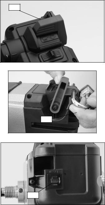
To turn lathe on, lift switch paddle (JJ) Fig. 22 up to the "ON" position. To turn lathe off, push switch paddle down
to the "OFF" position
LOCKING SWITCH IN THE "OFF" POSITION
 To reduce the risk of injury, in the event of a power outage (such as a breaker or fuse trip), always move the switch to the “OFF” position until the main power is restored.
IMPORTANT: When the machine is not in use, the switch should be locked in the "OFF" position to prevent unauthorized use, using a padlock (KK) Fig. 23 with a 1/4" (6.4 mm) diameter shackle.
MOTOR OVERLOAD PROTECTOR
The tool is equipped with a manual reset circuit breaker. If the tool is overloaded or stalled too long the circuit breaker will trip causing the tool to shut off.
To restart:
1.Set the ON/OFF switch to "OFF"
2.Allow the motor to cool 3-5 minutes.
3.Press the reset button (LL) Fig. 24.
4.Resume normal operations.
JJ
Fig. 22
KK
Fig. 23
LL
Fig. 24
13

MACHINE USE
 To reduce the risk of injury:
•Tighten all screws and levers securely when adjusting any part of the lathe.Also, be sure any lathe accessories are fastened and tightened before turning on the lathe.
•When using the included 3" (76 mm) faceplate (B) Fig. 25, do not mount pieces larger than 6" (152 mm) in diameter and up to 6" (152 mm) in length. For mounting larger pieces, be sure to use an appropriately sized faceplate.
•Keep hands off workpiece when it is spinning.
•Use only accessories recommended for this product and follow all instructions included with the accessories.
•Be sure cord is not in the way of the spinning workpiece or spinning lathe parts.
•Do not touch the tip of your turning tool directly after it has been used on the workpiece as it may be hot.
•Do not apply water or other coolants to lathe when it is spinning.
•Do not turn materials other than wood on this lathe. This lathe was designed for wood turning only.
•Be sure any chuck keys or wrenches are out of the chuck before operating the lathe.
•FOR THE DELTA® MODEL 46-460 MIDI-LATHE ONLY: Be sure to only use accessories equipped with locking set screws for turning the lathe in reverse. Also, do not switch lathe turning directions until the workpiece comes to a complete stop.
MOUNTING THE WORKPIECE
NOTE: When mounting a workpiece, first tap the spur center into the workpiece using a soft mallet before installing into headstock.
A typical bowl mount is shown in Fig. 25. Workpieces can be mounted to the faceplate through the faceplate's four holes using screws appropriate for the type of wood being turned.
Another type of workpiece mount, where the workpiece is fixed between the spur and live centers, is shown in Fig. 26. Here are some tips on this mount:
1.Mount the workpiece by moving the tailstock to a position about 1" or 1-1/2" (25 mm or 38 mm) from the end of the workpiece and locking it in this position.
2.Advance the live center (E) by turning the tailstock crank
(P)Fig. 27 until the center cup makes contact with the workpiece.
3.Do not support the workpiece on the center pin alone. Always have the rim of the center cup imbedded at least 1/8" (3.2 mm) into the workpiece.
4.Lock the quill locking screw (O).
B
Fig. 25
Fig. 26
E 
 O
O
P
Fig. 27
14

TURNING IN REVERSE (46-460 ONLY)
 FOR THE DELTA® MODEL 46-460 MIDILATHE ONLY: To reduce the risk of injury, be sure to only use accessories equipped with locking set screws for turning the lathe in reverse. Also, do not switch lathe turning directions until the workpiece comes to a complete stop.
Care should be taken not to stall the workpiece when turning in reverse. If a stall should occur, stop the lathe and verify that the chuck or faceplate is fully seated and both set screws are tight before continuing.
MM 
The lathe comes ready to turn forward (downwards |
Fig. 28 |
|
toward the user) for typical woodturning applications. |
|
|
However, some applications require the lathe to turn in |
|
|
reverse (upwards away from user). The 46-460 can turn |
|
|
in reverse. To do this: |
|
|
1. |
Be sure the lathe power switch is turned off and that |
|
|
the spindle is not spinning. |
|
2. |
Slide switch (MM) Fig. 28 to “FWD” (forward) or |
|
|
“REV” (reverse) position, depending on your desired |
|
|
rotation. |
|
NOTE: The forward/reverse switch (marked FWD/ REV) employs a lockout feature to prevent switching directions when the ON/OFF switch is in the raised, or "ON" position.
3. If using a faceplate, chuck or other accessory that must be screwed on to the spindle nose, be sure the set screws are securely tightened before running in reverse.
TROUBLESHOOTING
For assistance with your machine, visit our website at www.DeltaMachinery.com for a list of service centers or call the DELTA® Power Equipment Corporation help line at 1-800-223-7278
MAINTENANCE
 To reduce the risk of injury, turn unit off and disconnect it from power source before installing and removing accessories, before adjusting or when making repairs. An accidental start-up can cause injury.
KEEP MACHINE CLEAN
Periodically blow out all air passages with dry compressed air. All plastic parts should be cleaned with a soft damp cloth. NEVER use solvents to clean plastic parts. They could possibly dissolve or otherwise damage the material.
 To reduce the risk of injury, wear certified safety equipment for eye, hearing and respiratory protection while using compressed air.
FAILURE TO START
Should your machine fail to start, check to make sure the prongs on the cord plug are making good contact in the outlet. Also, check for blown fuses or open circuit breakers in the line.
LUBRICATION & RUST PROTECTION
Apply household floor paste wax to the machine table, extension table or other work surface weekly. Or use a commercially available protective product designed for this purpose. Follow the manufacturer’s instructions for use and safety.
To clean cast iron tables of rust, you will need the following materials: a medium sized scouring pad, a can of spray lubricant and a can of degreaser. Apply the spray lubricant and polish the table surface with the scouring pad. Degrease the table, then apply the protective product as described above.
15

PERIODIC MAINTENANCE
•Check that all fasteners are tightened properly.
•Check belt tension and adjust if necessary. See Changing Pulleys for instructions.
•Inspect belt for damage or wear and replace as needed. See below for belt replacement instructions.
•Inspect both faceplate set screws to ensure the cup edge is sharp and crisp. Replace if necessary.
BELT REPLACEMENT
1.Lift up pulley cover (X) Fig. 29.
2.Pull down belt tensioning lever (Y) Fig. 30 to release belt tension.
3.Remove spur center (G) Fig. 30, if attached.
4.Loosen two set screws (NN) Fig. 31 on the spindle handwheel (OO) Fig. 31 at least 2-3 turns to avoid damage to the threads during removal.
5.Engage indexing pin (FF) Fig. 31 and remove spindle handwheel (OO). (NOTE: Threads are left-hand. Turn handwheel clockwise to loosen and remove.)
6.Remove wave spring (PP) Fig. 32.
7.Loosen spindle pulley set screw (QQ) Fig. 33 with included hex wrench.
8.Grasp spindle pulley (RR) Fig. 34 with one hand and slide spindle shaft (SS) out with other hand in the tailstock direction.
9.Remove old belt and replace.
X
Fig. 29
OO |
NN |
 G
G
Y
Fig. 30
PP
FF
Fig. 31
Fig. 32
RR
SS |
|
|
Fig. 33 |
Fig. 34 |
|
16

10.Place new belt on spindle pulley making sure grooves in belt align with grooves in pulley.
11.Place spindle pulley (RR) inside headstock (as shown in Fig. 35) and hold as you insert the spindle shaft (SS) through headstock and pulley. Take care to align the shaft key (TT) with the pulley keyway (not shown).
12.Be sure the pulley seats firmly against the shaft shoulder (UU).
13.Tighten pulley set screw (QQ) Fig. 33 firmly.
14.Reinstall wave spring (PP) Fig. 32 and handwheel (OO) Fig. 31. Handwheel tightens counterclockwise. Tighten handwheel completely, then back off 1/4 turn. NOTICE: DO NOT OVER TIGHTEN. Doing so could damage the bearings.
15.Tighten two handwheel set screws (NN) Fig. 31 securely. With belt hanging loose, rotate spindle to ensure it turns freely.
16.Lift belt tensioning lever (Y) Fig. 30 up and snap it into place.
17.Check belt tension and adjust if needed. (See
Changing Pulleys section.)
18.Close pulley cover (X) Fig. 29 and side door (AA) Fig. 16 securely.
19.Disengage indexing pin (FF) Fig. 31 if it was engaged to remove spindle handwheel (OO).
 To reduce the risk of injury, do not operate lathe with pulley cover door open.
Do not turn on lathe with index pin engaged. Doing so could damage the lathe.
RR
TT UU
SS
Fig. 35
REPLACEMENT PARTS
Use only identical replacement parts. For a parts list or to order parts, visit our website at www.DeltaMachinery.com/service. You can also order parts from your nearest factory-owned branch, or by calling our Customer Care Center at 1-800-223-7278 to receive personalized support from highly-trained technicians.
FREE WARNING LABEL REPLACEMENT
If your warning labels become illegible or are missing, call 1-800-223-7278 for a free replacement.
SERVICE AND REPAIRS
All quality tools will eventually require servicing and/or replacement of parts. For information about DELTA® Power Equipment Corporation, its factory-owned branches, or an Authorized Warranty Service Center, visit our website at www.DeltaMachinery.com or call our Customer Care Center at 1-800-223-7278. All repairs made by our service centers are fully guaranteed against defective material and workmanship. We cannot guarantee repairs made or attempted by others.
You can also write to us for information at DELTA® Power Equipment Corporation, 99 Roush Street, Anderson, South Carolina 29625. - Attention: Product Service. Be sure to include all of the information shown on the nameplate of your tool (model number, type, serial number, etc.)
17
 Loading...