


14 in. Steel Frame Band Saw
Scie à ruban
avec structure en acier 355,6 mm (14 po)
Sierra cinta de bastidor de acero de 355.6 mm (14 pulg.)
Français (20)
Español (38)
www.DeltaMachinery.com
Instruction Manual
Manuel d’utilisation
Manual de instrucciones
INSTRUCTIVO DE OPERACIÓN, CENTROS |
-400 |
DE SERVICIO Y PÓLIZA DE GARANTÍA. |
|
LÉASE ESTE INSTRUCTIVO |
|
ANTES DE USAR EL PRODUCTO. |
|

TABLE OF CONTENTS
IMPORTANT SAFETY INSTRUCTIONS................................... |
2 |
SAFETY GUIDELINES - DEFINITIONS.................................... |
3 |
GENERAL SAFETY RULES ...................................................... |
3 |
ADDITIONAL SPECIFIC SAFETY RULES ............................... |
4 |
POWER CONNECTIONS .......................................................... |
5 |
MOTOR SPECIFICATIONS ....................................................... |
5 |
GROUNDING INSTRUCTIONS ................................................ |
5 |
EXTENSION CORDS ................................................................ |
6 |
KEY FEATURES AND COMPONENTS .................................... |
7 |
FUNCTIONAL DESCRIPTION .................................................. |
7 |
PRODUCT SPECIFICATIONS................................................... |
8 |
UNPACKING .............................................................................. |
8 |
ASSEMBLY ................................................................................ |
9 |
Stand Assembly .................................................................. |
9 |
Secure Table To Table Trunnion System ............................. |
9 |
Attach the Saw to the Stand............................................... |
9 |
Install Blade Tensioning Knob........................................... |
10 |
Install Band Saw Blade ..................................................... |
10 |
Adjust the Blade Tracking ................................................ |
11 |
Insert Throat Plate ............................................................. |
11 |
Square Table to Blade ...................................................... |
11 |
OPERATION ............................................................................ |
12 |
STARTING AND STOPPING THE SAW ............................ |
12 |
Using the Safety Key to Lock the |
|
Switch In the "Off" Position............................................... |
12 |
Selecting Proper Cutting Speed ....................................... |
12 |
Tilting the Table.................................................................. |
13 |
Positioning The Upper Blade Guide.................................. |
13 |
Cutting Curves................................................................... |
14 |
ADJUSTMENTS....................................................................... |
14 |
Adjusting the Blade Tension.............................................. |
14 |
Adjusting the Blade Guides and Bearings........................ |
15 |
Adjusting the Blade Tracking............................................. |
15 |
MAINTENANCE PROCEDURES ............................................ |
16 |
Lubrication ........................................................................ |
16 |
TROUBLE SHOOTING ........................................................... |
16 |
ABOUT BAND SAW BLADES................................................. |
18 |
TIPS .......................................................................................... |
18 |
ACCESSORIES........................................................................ |
18 |
WARRANTY ............................................................................. |
18 |
REPLACEMENT PARTS.......................................................... |
19 |
SERVICE AND REPAIRS......................................................... |
19 |
FRANÇAIS................................................................................ |
20 |
ESPAÑOL ................................................................................. |
38 |
IMPORTANT SAFETY INSTRUCTIONS
READ AND UNDERSTAND ALL WARNINGS AND OPERATING INSTRUCTIONS BEFORE USING THIS EQUIPMENT. Failure to follow all instructions listed below, may result in electric shock, fire,
and/or serious personal injury or property damage.
Woodworking can be dangerous if safe and proper operating procedures are not followed. As with all machinery, there are certain hazards involved with the operation of the product. Using the machine with respect and caution will considerably lessen the possibility of personal injury. However, if normal safety precautions are overlooked or ignored, personal injury to the operator may result. Safety equipment such
as guards, push sticks, hold-downs, featherboards, goggles, dust masks and hearing protection can reduce your potential for injury. But even the best guard won’t make up for poor judgment, carelessness or inattention. Always use common sense and exercise caution in the workshop. If a procedure feels dangerous, don’t try it. Figure out an alternative procedure that feels safer. REMEMBER: Your personal safety is your responsibility. For additional information please visit our website www.DeltaMachinery.com.


 This machine was designed for certain applications only. DELTA® Power Equipment Corporation strongly recommends that this machine not be modified and/or used for any application other than that for which it was designed. If you have any questions relative to a particular application, DO NOT use the
machine until you have first contacted DELTA® to determine if it can or should be performed on the product.
If you have any questions relative to its application DO NOT use the product until you have written DELTA® Power Equipment Corporation and we have advised you. Contact us online at www.DeltaMachinery.com or by mail at Technical Service Manager, DELTA® Power Equipment Corporation, 99 Roush Street, Anderson, SC 29625.
Information regarding the safe and proper operation of this tool is available from the following sources:
•Power Tool Institute, 1300 Sumner Avenue, Cleveland, OH 44115-2851or online at www.powertoolinstitute.com
•National Safety Council, 1121 Spring Lake Drive, Itasca, IL 60143-3201
•American National Standards Institute, 25 West 43rd Street, 4 floor, New York, NY 10036 www.ansi.org - ANSI 01.1 Safety Requirements for Woodworking Machines
•U.S. Department of Labor regulations www.osha.gov
2

SAFETY GUIDELINES - DEFINITIONS
This manual contains information that is important for you to know and understand. This information relates to protecting YOUR SAFETY and PREVENTING EQUIPMENT PROBLEMS. To help you recognize this information, we use the symbols below. Please read the manual and pay attention to these sections.
Indicates an imminently hazardous situation which, if not avoided, will result in death or serious injury.
Indicates a potentially hazardous situation which, if not avoided, could result in death or serious injury.
Indicates a potentially hazardous situation which, if not avoided, may result in minor or moderate injury.
Used without the safety alert symbol indicates potentially hazardous situation which, if not avoided, may result in property damage.
GENERAL SAFETY RULES
 WARNING FAILURE TO FOLLOW THESE RULES MAY RESULT IN SERIOUS PERSONAL INJURY.
•FOR YOUR OWN SAFETY, READ AND UNDERSTAND THE INSTRUCTION MANUAL BEFORE OPERATING THE UNIT. Learn the unit’s application and limitations as well as the specific hazards peculiar to it.
•KEEP WORK AREA CLEAN. Cluttered areas and benches invite accidents.
•DON’T USE IN DANGEROUS ENVIRONMENT. Don’t use this unit in damp or wet locations, or expose it to rain. Keep work area well-lighted.
•KEEP CHILDREN AND VISITORS AWAY. All children and visitors should be kept a safe distance from work area.
•DISCONNECT UNIT before servicing.
•CHECK DAMAGED PARTS. Before further use of the unit, properly repair or replace any part that is damaged.
 FAILURE TO FOLLOW THESE RULES MAY RESULT IN SERIOUS INJURY.
1.Read and understand the warnings posted on the machine and in this manual. Failure to comply with all of these warnings may cause serious injury.
2.Replace the warning labels if they become obscured or removed.
3.This machine is designed and intended for use by properly trained and experienced personnel only. If you are not familiar with the proper and safe operation of a band saw, do not use until proper training and knowledge have been obtained.
4.Do not use this machine for other than its intended use. If used for other purposes, DELTA® Power Equipment Corporation disclaims any real or implied warranty and holds itself harmless from any injury that may result from that use.
5.Always wear approved safety glasses/face shields while using this band saw.
6.Before operating this band saw, remove tie, rings, watches and other jewelry, and roll sleeves up past the elbows. Remove all loose clothing and confine long hair. Non-slip footwear or anti-skid floor strips are recommended. Do not wear gloves.
7.Wear ear protectors (plugs or muffs) during extended periods of operation.
8.Some dust created by power sanding, sawing, grinding, drilling and other construction activities contain chemicals known to cause cancer,
birth defects or other reproductive harm. Some examples of these chemicals are:
•Lead from lead based paint.
•Crystalline silica from bricks, cement and other masonry products.
•Arsenic and chromium from chemically treated lumber.
Your risk of exposure varies, depending on how often you do this type of work. To reduce your exposure to these chemicals, work in a well-ventilated area and work with approved safety equipment, such as face or dust masks that are specifically designed to filter out
microscopic particles.
9.Do not operate this machine while tired or under the influence of drugs, alcohol or any medication.
10.Make certain the switch is in the OFF position before connecting the machine to the power source.
11.Make certain the machine is properly grounded.
12.Make all machine adjustments or maintenance with the machine unplugged from the power source.
13.Form a habit of checking to see that all extra equipment such as adjusting keys, wrenches, scrap, stock, and cleaning rags are removed away from the machine before turning on.
continued on page 4
3

14.Keep safety guards in place at all times when the machine is in use. If removed for maintenance purposes, use extreme caution and replace the guards immediately when maintenance is complete.
15.Make sure the tool is firmly secured to the floor before use.
16.Check damaged parts. Before further use of the machine, a guard or other part that is damaged should be carefully checked to determine that it will operate properly and perform its intended function. Check for alignment of moving parts, binding of moving parts, breakage of parts, mounting and any other conditions that may affect its operation. A guard or other part that is damaged should be properly repaired or replaced.
17.Provide for adequate space surrounding work area and non-glare, overhead lighting.
18.Keep the floor around the machine clean and free of scrap material, oil and grease.
19.Keep visitors a safe distance from the work area. Keep children away.
20.Make your workshop child proof with padlocks, master switches or by removing starter keys.
21.Give your work undivided attention. Looking around, carrying on a conversation and “horseplay" are careless acts that can result in serious injury.
22.Maintain a balanced stance at all times so that you do not fall or lean against the tool or its moving parts. Do not overreach or use excessive force to perform any machine operation.
23.Use the right tool at the correct speed and feed rate. Do not force a tool or attachment to do a job for which it was not designed. The right tool will do the job better and safer.
24.Use recommended accessories; improper accessories may be hazardous.
25.Maintain machinery with care. Follow instructions for lubricating and changing accessories.
26.Turn off the machine before cleaning. Use a brush or compressed air to remove dust or debris — do not use your hands.
27.Do not stand on the machine. Serious injury could occur if the machine tips over.
28.Never leave the machine running unattended. Turn the power off and do not leave the machine until it comes to a complete stop.
29.At all times, hold the stock firmly.
30.Do not use this tool for other than it intended use. If used for other purposes, DELTA® Power Equipment Corporation disclaims any real or implied warranty and holds itself harmless for any injury or damage which may result from that use.
Familiarize yourself with the following safety notices used in this manual:
This means that if precautions are not heeded, it may result in minor injury and/or possible machine damage.
This means that if precautions are not heeded, it may result in serious injury or possibly even death.
ADDITIONAL SPECIFIC SAFETY RULES
1.Use proper blade size and type.
2.Adjust the upper blade guide so that it is about 1/8” above the workpiece.
3.Properly adjust the blade tension, tracking, blade guides, and blade support bearings.
4.Never start the machine with the workpiece against the blade.
5.Hold workpiece firmly and feed into blade at a moderate speed.
6.Turn the machine “off” to back out of an uncompleted or jammed cut.
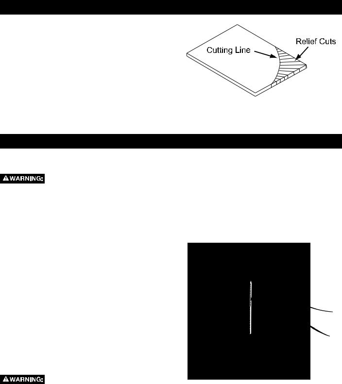
7.Make “relief” cuts prior to cutting long curves.
8.Turn the machine “off” and wait for the blade to stop prior to cleaning the blade area, removing debris near the blade, removing or securing workpiece, or changing the angle of the table. A coasting blade can be dangerous.
SAVE THESE INSTRUCTIONS.
Refer to them often and use them to instruct others.
4

POWER CONNECTIONS
A separate electrical circuit should be used for your machines. This circuit should not be less than #12 wire and should be protected with a 20 Amp time lag fuse. If an extension cord is used, use only 3-wire extension cords which have 3-prong grounding type plugs and matching receptacle which will accept the machine’s plug. Before connecting the machine to the power line, make sure the switch (s) is in the "OFF" position and be sure that the electric current is of the same characteristics as indicated on the machine. All line connections should make good contact. Running on low voltage will damage the machine.
DO NOT EXPOSE THE MACHINE TO RAIN OR OPERATE THE MACHINE IN DAMP LOCATIONS.
GROUNDED |
GROUNDED OUTLET BOX |
|||
OUTLET BOX |
|
|
|
|
CURRENT |
|
|
GROUNDING |
|
|
|
|
MEANS |
|
CARRYING |
|
|
|
|
|
|
|
|
|
PRONGS |
|
|
|
ADAPTER |
GROUNDING BLADE
IS LONGEST OF THE 3 BLADES
Fig. A |
Fig. B |
MOTOR SPECIFICATIONS
Your machine is wired for 120/240 volts, 60 HZ alternating current. Before connecting the machine to the power source, make sure the switch is in the "OFF" position.
GROUNDING INSTRUCTIONS
THIS MACHINE MUST BE GROUNDED WHILE IN USE TO PROTECT THE OPERATOR FROM ELECTRIC SHOCK.
1. All grounded, cord-connected machines:
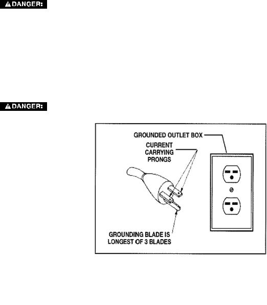
In the event of a malfunction or breakdown, grounding provides a path of least resistance for electric current to reduce the risk of electric shock. This machine is equipped with an electric cord having an equipment-grounding conductor and a grounding plug. The plug must be plugged into a matching outlet that is properly installed and grounded in accordance with all local codes and ordinances.
Do not modify the plug provided - if it will not fit the outlet, have the proper outlet installed by a qualified electrician.
Improper connection of the equipment-grounding conductor can result in risk of electric shock. The conductor with insulation having an outer surface that is green with or without yellow stripes is the equipment-grounding conductor. If repair or replacement of the electric cord or plug is necessary, do not connect the equipment-grounding conductor to a live terminal.
Check with a qualified electrician or service personnel if the grounding instructions are not completely understood, or if in doubt as to whether the machine is properly grounded.
Use only 3-wire extension cords that have 3-prong grounding type plugs and matching 3-conductor receptacles that accept the machine’s plug, as shown in Fig. A.
Repair or replace damaged or worn cord immediately.
2.Grounded, cord-connected machines intended for use on a supply circuit having a nominal rating less than 150 volts:
If the machine is intended for use on a circuit that has an outlet that looks like the one illustrated in Fig. A, the machine will have a grounding plug that looks like the plug illustrated in Fig. A. A temporary adapter, which looks like the adapter illustrated in Fig. B, may be used to connect this plug to a matching 2-conductor receptacle as shown in Fig. B if a properly grounded outlet is not available. The temporary adapter should be used only until a properly
5
grounded outlet can be installed by a qualified electrician. The green-colored rigid ear, lug, and the like, extending from the adapter must be connected to a permanent ground such as a properly grounded outlet box. Whenever the adapter is used, it must be held in place with a metal screw.
NOTE: In Canada, the use of a temporary adapter is not permitted by the Canadian Electric Code.
In all cases, make certain that the receptacle in question is properly grounded. If you are not sure, have a qualified electrician check the receptacle.
IN ALL CASES, MAKE CERTAIN THE RECEPTACLE IN QUESTION IS PROPERLY GROUNDED. IF YOU ARE NOT SURE, HAVE A qualified ELECTRICIAN CHECK THE RECEPTACLE.
3. 240 VOLT Single-Phase Operation:
The motor supplied with your machine is a dual voltage, 120/240 volt motor. It is shipped ready-to-run for 120 volt operation. However, it can be converted for 240 volt operation.
A qualified electrician should do the conversion, or the machine can be taken to an Authorized Delta Service Center. When completed, the machine must conform to the National Electric Code and all local codes and ordinances.
The machine is converted by re-wiring the motor for 240 volts, installing a 240 volt plug on the power supply cord and replacing the switch with one that is rated for 240 volt operation. Be sure the 240 volt plug is only used in an outlet having the same configuration as the plug illustrated in Fig. C. No adapter should be used with the 240 volt plug.
IN ALL CASES, MAKE CERTAIN THE RECEPTACLE IN QUESTION IS PROPERLY GROUNDED. IF YOU ARE NOT SURE, HAVE A qualified ELECTRICIAN CHECK THE RECEPTACLE.
Fig. c
EXTENSION CORDS |
MINIMUM GAUGE EXTENSION CORD |
|||||||
|
|
|
Use proper extension cords. |
RECOMMENDED SIZES FOR USE WITH STATIONARY ELECTRIC MACHINES |
||||
|
|
|
Make sure your extension cord is |
Ampere |
Volts |
Total Length |
Gauge of Extension |
|
|
|
|
||||||
in good condition and is a 3-wire extension cord |
Rating |
|
of Cord in |
Cord |
||||
|
|
Feet |
|
|||||
which has a 3-prong grounding type plug and |
|
|
|
|||||
0-6 |
120 |
up to 25 |
18 AWG |
|||||
matching receptacle which will accept the |
||||||||
0-6 |
120 |
25-50 |
16 AWG |
|||||
machine’s plug. When using an extension cord, |
||||||||
0-6 |
120 |
50-100 |
16 AWG |
|||||
be sure to use one heavy enough to carry the |
||||||||
0-6 |
120 |
100-150 |
14 AWG |
|||||
current of the machine. An undersized cord will |
6-10 |
120 |
up to 25 |
18 AWG |
||||
cause a drop in line voltage, resulting in loss of |
||||||||
6-10 |
120 |
25-50 |
16 AWG |
|||||
power and overheating. The table shows the |
6-10 |
120 |
50-100 |
14 AWG |
||||
correct gauge to use depending on the cord |
6-10 |
120 |
100-150 |
12 AWG |
||||
length. If in doubt, use the next heavier gauge. |
10-12 |
120 |
up to 25 |
16 AWG |
||||
The smaller the gauge number, the heavier the |
10-12 |
120 |
25-50 |
16 AWG |
||||
cord. |
10-12 |
120 |
50-100 |
14 AWG |
||||
10-12 |
120 |
100-150 |
12 AWG |
|||||
|
|
|
|
|||||
|
|
|
|
12-16 |
120 |
up to 25 |
14 AWG |
|
|
|
|
|
12-16 |
120 |
25-50 |
12 AWG |
|
|
|
|
|
12-16 |
120 |
|
|
|
|
|
|
|
greater than 50 feet not recommended |
||||
|
|
|
|
|
|
|||
|
|
|
|
|
|
|
|
|
6
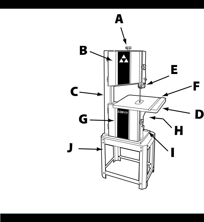
KEY FEATURES AND COMPONENTS
A. Blade Tensioning Knob
B. Upper Wheel Guard
C. Power Switch
D. Cast Iron Tilting Table
E. Blade Guide Assembly
F. Miter Gauge T-Slot
G. Lower Wheel Guard
H. 1 HP Motor
I. Belt Tensioning Handle
J. Tool Stand
Fig. 1
FUNCTIONAL DESCRIPTION
The DELTA® 14" Steel Frame Band Saw, MODEL 28-400, is designed for various re-sawing, cross-cutting and ripping operations for material up to 6 " in height and 13-5/8 " in width. It features a 1HP, two-speed motor and can accommodate blades from 1/8 " to 3/4 " in width.
7

PRODUCT SPECIFICATIONS
Motor |
1 HP, 120V |
Cutting Capacity - Height |
6" |
|
|
Cutting Capacity - Width |
13-5/8" |
|
|
Minimum Blade Width |
1/8" |
Maximum Blade Width |
3/4" |
|
|
Blade Length |
93-1/2" |
|
|
Blade Speed - Low |
1620 ft./min (490m/min.) |
|
|
Blade Speed - High |
3340 ft./min (990m/min) |
|
|
Table Size |
15-3/4" X 18-7/8" |
Table T-Slot Size (DxW) |
3/8" X 3/4" |
|
|
Table Height From Floor |
40-3/4" |
|
|
Table Tilt |
3° left - 45° right |
Dust Port Diameter |
4" |
|
|
Overall Dimensions (HxWxD) |
27" X 19" X 65-1/2" |
|
|
Net Weight |
180 Lbs. |
Shipping Weight |
165 Lbs. |
|
|
Unpacking
Carefully unpack the machine and all loose items from the shipping container(s). Remove the rust-preventative oil from unpainted surfaces using a soft cloth moistened with mineral spirits, paint thinner or denatured alcohol.
Do not use highly volatile solvents such as gasoline, naphtha, acetone or lacquer thinner for cleaning your machine. After cleaning, cover the unpainted surfaces with a good quality household floor paste wax.
NOTICE: The manual cover illustrates the current production model. All other illustrations contained in the manual are representative only and may not depict the actual labeling or accessories included. These are intended to illustrate technique only.
The machine is heavy, be careful when removing it from the shipping container! Failure to comply may cause serious injury and/or damage to the sander and/or property!
Your DELTA® 14" Steel Frame Band Saw comes packed in a single container. Use a safety strap to avoid tip-over when lifting machine. Check shipping carton and machine for damage before unpacking.
Open the shipping container. Carefully remove packaging materials, parts and machine from shipping carton. Always check for and remove protective shipping materials around motors and moving parts. Lay out all parts on a clean work surface and check that all parts are present and in good condition:
Description (Quantity)
•Stand Legs (4)
•Bottom Stand Braces (4)
•Stand Top (1)
•Stand Hardware Pack (1)
•Cast Iron Work Table (1)
•Top Trunnion (1)
•93 ½" Band Saw Blade (1)
•Blade Tensioning Handle (1)
•Throat Plate (1)
•Hardware Pack (1)
Contents of Stand |
Contents of Tool |
Hardware Pack |
Hardware Pack |
• M6 X 16 Carriage Bolts (24) |
• M8 X 20 Hex Bolts (8) |
• M6 FLAT Washers (24) |
• M6 Lock Washers (4) |
• M6 HEX Nuts (24) |
• M6 Flat Washers (4) |
• Rubber Feet (4) |
• (size) Trunnion Feed Bolt (1) |
|
• 8MM Flat Washer (1) |
|
• Table Tilt Locking Wing Nut (1) |
|
• M8 Flat Washers (4) |
|
• M8 Lock Washers (4) |
|
• M8 Hex Nuts (4) |
8

ASSEMBLY
STAND ASSEMBLY
Refer to Figure 2
• Place top surface (A) upside down on a level surface. Attach the four legs (B) to the top using M6 X 16 carriage bolts, M6 flat washers, and M6 hex nuts.
• Attach bottom rail supports (C) using M6 X 16 carriage bolts, M6 flat washers, and M6 hex nuts.
• Place rubber feet (D) on bottom of legs. Turn assembled stand upright.
Figure 2
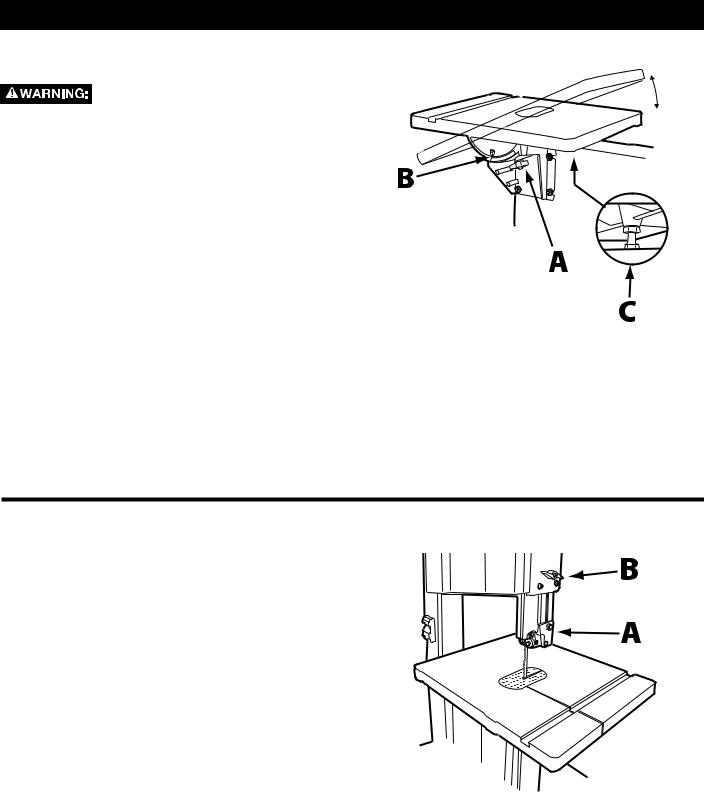
SECURE TABLE TO TABLE TRUNNION SYSTEM
Refer to Figure 3
•Locate the four mounting holes (A) in the upper trunnion and attach the upper trunnion to the underside of the table using four M8 X 20 hex bolts,
M6 lock washers, and M6 flat washers
• Position the table assembly so that the upper trunnion fits into the lower trunnion and the trunion feed bolt (B) extends through the slot in the lower
trunnion.
NOTE: The table tilt indicator (C) on the top trunnion should align with table tilt scale (D) on the bottom trunnion.
• Secure trunnion feed bolt using an 8MM flat washer
and black table tilt locking wing nut (E).
Figure 3
ATTACHING THE SAW TO THE STAND
See Figure 4.
This step requires two adults. The DELTA® 14" Steel Frame Band Saw is heavy, be careful when lifting and
handling it! Failure to comply may cause serious injury and/or damage to the machine and/or property!
Carefully lift the saw onto the assembled stand and align the four holes in base of the saw with the holes in the top of the stand. Secure saw to the stand using four M8 X 20 hex head bolts with M8 flat washer, M8 lock washer and M8 hex nut.
Figure 4
9
ASSEMBLY
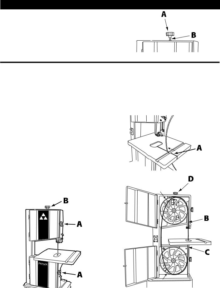
INSTALL BLADE TENSIONING KNOB
•Fit the blade tensioning knob (A) onto the blade tensioning spindle (B) located at the top of the
machine.
Figure 5
INSTALL BAND SAW BLADE
•Open the upper and lower cabinets of the saw by turning the cabinet lock knobs (A) clockwiseSee Figure 6.
•Locate the blade tensioning knob (B) at the top of the machine and turn it counterclockwise several rotations to lower the upper flywheel.
•Carefully feed the blade through the slot in the table (A), ensuring that the blade teeth are pointing down
toward the table. See Figure 7.
• Once the blade is in the throat of the saw table, rotate it clockwise 90°, toward you. The blade teeth should now be facing you.
• Carefully slide the blade through the upper slot (B) and lower slot (C) located to the right of the wheel guard.
• Loop the upper part of the blade over the upper tire |
|
|
and the lower part of the blade over the lower tire. |
|
|
See Figure 8. If you need to create additional slack, |
|
|
rotate the blade tensioning knob (D) counterclockwise |
Figure 7 |
|
until the blade can be slipped over both flywheels |
||
|
•Tighten the blade tensioning knob until there is sufficient tension on blade. (See “Adjusting the Blade
Tension", page 13).
Figure 6
NOTE: Once your DELTA® Band Saw is set up, you may want to cut several scraps of various species and thicknesses of wood. Check for bowing in the cut and add more tension to the blade if necessary. Different blade sizes will also require different tension settings.
10
ASSEMBLY |
|
ADJUST THE BLADE TRACKING |
|
See Figure 9. |
|
Disconnect the machine from the |
|
power source before making any |
|
adjustments! |
|
IMPORTANT: Before tracking the blade, confirm that |
|
the blade guides and blade support bearings are clear |
|
of the blade. |
|
• After applying tension to the blade, open the upper |
|
wheel guard. |
|
• Rotate the wheel slowly forward by hand and observe |
|
the blade’s movement. It should travel in the center of |
|
the upper tire. |
|
• If the blade creeps toward the front edge, unlock the |
|
blade tracking lock (A) and turn the blade tracking |
|
knob (B) clockwise until the blade consistently tracks |
Figure 9 |
in the middle of the tire. |
|
• If the blade creeps towards the rear of the tire, adjust |
|
the blade tracking knob counterclockwise. |
|
• Lock the blade tracking lock and close and lock the |
|
upper wheel guard. |
|
INSERT THROAT PLATE
See Figure 10.
Disconnect the machine from the power source!
•Fit the throat plate (A) in the throat of the table so that the tab on the throat plate fits into the notch in table.
•Check to ensure the front of the throat plate is not higher than the table surface. To adjust the height of the throat plate, rotate the two set screws (B) either up or down
Figure 10
SQUARE TABLE TO BLADE
Disconnect the machine from the power source!
Place a carpenters square (A) against the front and back side of the blade and check the alignment of the table. If the table is out of square, refer to Figure 11 and proceed as follows:
•Raise the upper blade guide assembly by loosening the lock knob (B).
•Loosen the flange nut (C) on the lower trunnion using a 12MM open end wrench and adjust the set screw until the table is square with the blade from the front and back.
•Tighten the flange nut and use the square to confirm proper position of the table
•Check the pointer on the tilt scale, located on the lower trunnion, and reset if necessary to read 0°.
Figure 11
11

OPERATION
STARTING AND STOPPING THE SAW
 Make sure that the switch is in the “OFF" position before plugging cord into outlet. Do not touch the plug’s metal prongs when
unplugging or plugging in the cord
Do not attempt to operate this tool without first connecting it to an
adequate dust collection system
NOTE: The DELTA® 14" Steel Frame Band Saw uses a Safety Key (A), shown in Figure 12. The Safety Key
must be in place in order to operate the machineBefore attempting to turn on the band saw, ensure the Safety
Key is installed.
The power switch is located on the left side of the machine. To turn the machine "ON", ensure the yellow safety key is installed and lift the red power switch (B) To turn the machine "OFF", press up on the red power switch.
In the event of a power outage (such as a breaker or fuse trip), always move the
switch to the “OFF" position until the main power is Figure12 restored.
USING THE SAFETY KEY TO LOCK THE SWITCH IN THE "OFF" POSITION
When the tool is not in use, the switch should be locked in the “OFF" position. This can be done by grasping the Safety Key (A), shown in Figure 12 above, and pulling it out of the switch. With the Safety Key removed the switch will not operate. Should the Safety
Key be removed while the machine is running, the switch can be turned “OFF" once, but cannot be restarted without inserting the Safety Key.
IMPORTANT: Store the Safety Key away from the tool to prevent unauthorized use
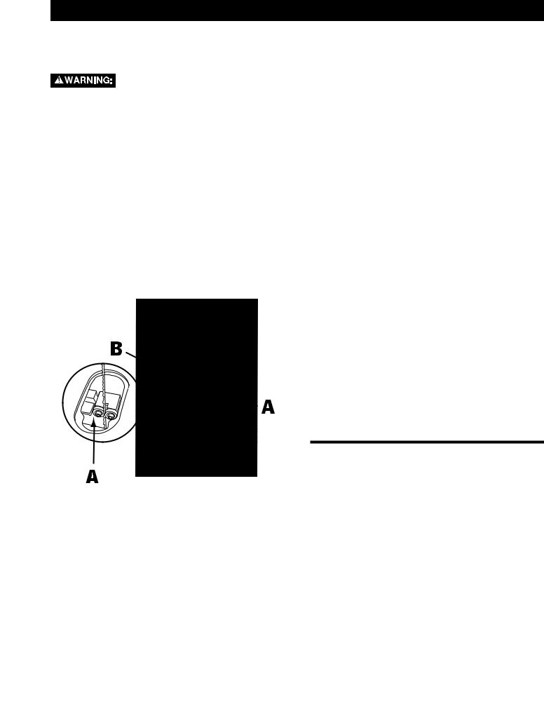
SELECTING PROPER CUTTING SPEED
Your DELTA® 14" Steel Frame Band Saw has two cutting speeds: low (1620 ft./min )and high (3340 ft./ min). The cutting speed is determined based on which of the two pulley wheels, shown in Figure 13 is in use.
The larger diameter pulley wheel (A) is used for the lower cutting speed while the smaller diameter wheel
(B) is used for the higher speed.
• To change the cutting speed, open the lower wheel guard (C).
• Refer to the diagram and instructions (D) posted on the inside of the wheel guard.
• Reduce tension on the pulley belt using the belt tensioning knob (E).
•Place belt on the proper wheels and hand turn to ensure it tracks in the center of both wheels.
• |
Re-tension pulley belt using the belt tensioning knob. |
Figure 13 |
• |
Close the lower wheel guard. |
|
12
operation
TILTING THE TABLE
Disconnect the machine from the power source!
See Figure 14.
You can tilt the band saw table up to 45° to the right. To tilt the table to the right.
•Loosen the black table tilt locking wing nut (A), located underneath the lower trunnion.
•Tilt the table to the desired angle as shown on the tilt scale (B).
•Retighten the table tilt locking wing nut.
The table can also be tilted 3° to the left for applications such as cutting cast moldings. To tilt the table to the left:
•Follow the instructions above and tilting the table to the right. The table should be tilted enough to allow access to the 0° stop bolt (C) located on the lower trunnion.
•Remove the 0° stop bolt.
•Loosen the table tilt locking wing nut, tilt the table all the way to left.
•Retighten the table tilt locking wing nut.
Figure 14
POSITIONING THE UPPER BLADE GUIDE
IMPORTANT: Proper positioning of the upper blade guide is required to ensure an accurate cut. It also serves to prevent operators fingers from coming in contact with the saw blade.
See Figure 15.
The upper blade guide (A) should be positioned approximately 1/16" above the top of the workpiece, just high enough to allow the workpiece to pass under the blade guide assembly.
To set the upper blade guide to the proper height:
•Loosen the lock knob (B) and move the blade guide assembly to the desired position.
•Retighten the lock knob.
IMPORTANT: Prior to using the band saw, always check guide post lock knob and tighten if necessary.
Figure 15
13
OPERATION
CUTTING CURVES
Turn the stock carefully so that the blade follows without twisting. For very abrupt curves, consider using a narrower blade, or a blade with more set. Another solution to this problem is to make relief cuts (Figure 16)
When you withdraw the workpiece or change the cut, be careful not to accidentally pull the blade off of the wheels. The preference is to turn the stock and saw out through the waste material.
Figure 16
ADJUSTMENTS
ADJUSTING THE BLADE TENSION
Disconnect the machine from the power source before making any adjustments!
See Figure 17 (show set up as in sample to the rightCaption: A standard blade should have approximately 1/4" deflection on either side.)
Unless you have a tension meter, achieving optimum blade tension is a matter of trial and error. There are a number of suggested methods for achieving the proper tension.
Most blade manufacturers recommend 15,000 psi to 20,000 psi for a common carbon-steel blade. Stronger bimetal, spring-steel, and carbide-tipped blades generally require 25,000 psi to 30,000 psi. The tighter the blade is stretched, the more rigid it becomes and the less tendency it will have to deflect in the cut.
It should be noted that maximum blade tension is only required for the most demanding cuts, such as re-sawing dense hardwoods or stock of maximum thickness.
NOTE: DELTA® Timber Wolf® band saw blades are recommended as they are designed to operate with less tension, thus increasing their serviceable life. Follow the tensioning directions on the package
To check and adjust the blade tension on your DELTA® 14" Steel Frame Band Saw, do the following:
Disconnect the machine from the power source before making any adjustments!
•Set the upper blade guide assembly about 6 in. off the table.
•Use a moderate amount of pressure with your index finger to push the blade sideways in both directions. The blade should not deflect more than 1/4" in either direction.
•If the blade deflects more than 1/4", increase the tension on the blade by tightening the blade
tensioning knob at the top of the machine (refer to B in Figure 6, page 9).
•If the blade does not deflect at all, it may be too tight. Loosen the blade tensioning knob slightly until there is a minimal amount of deflection.
Figure 17
14
ADJUSTMENTS
ADJUSTING THE BLADE GUIDES AND BEARINGS
See Figure 18.
Disconnect the machine from the power source before making any adjustments!
Adjust the upper blade guides and blade support bearings only after the blade has the correct tension and is tracking properly.
The DELTA® 14" Steel Frame Band Saw features two upper and lower side bearings and two upper and lower rear bearings that can be adjusted in order to ensure straight and consistent cuts. It is recommended that you periodically check the position of all bearings and adjust if necessary.
Side Bearings
The upper and lower side bearings (A) should be positioned so that there is approximately 1/64" gap on either side of the blade. To adjust the position of the bearings, side-to-side, do the following:
•Use a 3MM Allen wrench to loosen the bearing screws (B).
•Reposition the bearings and tighten the bearing the screws.
The upper and lower side bearings also adjust back and forth and should be positioned so that the front edge of the bearings is just behind the blade gullet. To adjust the position of the bearings, front-to-back, do the following:
•Use a 13MM open wrench to loosen the top retaining nut and a 10MM open wrench to loosen the bottom retaining nut. (The bottom retaining nut can be made more accessible by tilting the table slightly.)
•With the retaining nut loosened, both upper side bearings or both lower side bearings will move back and forth as a unitPosition them so that the front edge of the bearings are just behind the blade gullet.
•Re-tighten the retaining nuts.
Rear Bearings
NOTE: The upper and lower side bearings must both be set in place prior to adjusting the upper and lower rear bearings.
The upper and lower rear bearings should be positioned so that they nearly touch the blade.
•To adjust, use a 3MM Allen wrench to loosen the bearing screws.
•Reposition the bearings and tighten the bearing the screws.
|
ADJUSTING BLADE TRACKING |
|
See “Adjust Blade Tracking" in the Assembly section of |
Figure 18 |
this manual on page 10. |
15

MAINTENANCE
STARTING AND STOPPING THE SAW
Make sure that the switch is in the "OFF" postion. To reduce the risk of injury, turn unit off and disconnect it from power source
before installing and removing accessories, before adjusting or when making repairs.
An accidental start-up can cause injury.
FAILURE TO START
Should your machine fail to start, check to make sure the prongs on the cord plug are making good contact in the outlet. Also, check for blown fuses or open circuit breakers in the line.
KEEP MACHINE CLEAN
Periodically blow out all air passages with dry compressed air. All plastic parts should be cleaned with a soft damp cloth.
NEVER use solvents to clean plastic parts. They could possibly dissolve or otherwise damage the material.
Wear certified safety equipment for eye, hearing and respiratory protection while
using compressed air
LUBRICATION & RUST PROTECTION
Apply household floor paste wax to the machine table, extension table or other work surface weekly. Or use a commercially available protective product designed for this purpose. Follow the manufacturer’s instructions for use and safety.
To clean cast iron tables of rust, you will need the following materials: a sheet of medium Scotch-Brite™ Blending Hand Pad, a can of WD-40® and a can of degreaser. Apply the WD-40 and polish the table surface with the Scotch-Brite pad.
Degrease the table, then apply the protective product as described above.
TROUBLESHOOTING
In spite of how well a band saw is maintained, problems can occur. The following troubleshooting guide will help you solve the more common problems:
TROUBLE: SAW WILL NOT START.
Probable Cause |
Remedy |
||
1. |
Saw not plugged in. |
1. |
Plug in saw. |
2. |
Fuse blown or circuit breaker tripped. |
2. |
Replace fuse or reset circuit breaker. |
3. |
Cord damaged. |
3. |
Have cord replaced. |
|
|
|
|
TROUBLE: BREAKER KICKS OUT FREQUENTLY.
Probable Cause |
Remedy |
||
1. |
Extension cord too light or too long. |
1. |
Replace with adequate size cord. |
2. |
Feeding stock too fast. |
2. |
Feed stock more slowly. |
3. |
Blade in poor condition (dull, warped, gummed). |
3. |
Clean or replace blade. |
4. |
Low voltage supply. |
4. |
Contact an electrician |
|
|
|
|
TROUBLE: BAND SAW VIBRATES EXCESSIVELY. |
|
|
|
|
|
||
Probable Cause |
Remedy |
||
1. |
Machine not mounted securely to stand. |
1. |
Tighten all mounting hardware. |
2. |
Stand on uneven surface. |
2. |
Reposition on flat level surface. |
3. |
Worn belt. |
3. |
Replace belt. |
4. |
Pulley not aligned. |
4. |
Adjust pulleys. |
5. |
Motor not fastened securely. |
5. |
Tighten all mounting hardware. |
|
|
|
|
16

TROUBLESHOOTING
TROUBLE: BAND SAW DOES NOT COME UP TO SPEED.
Probable Cause |
Remedy |
||
1. |
Low voltage due to improper extension cord size. |
1. |
Replace with adequate size cord. |
2. |
Low voltage. |
2. |
Contact an electrician. |
|
|
|
|
TROUBLE: BLADES BREAK.
Probable Cause |
Remedy |
||
1. |
Blade not tensioned properly. |
1. |
Adjust blade tension. |
2. |
Blade guides improperly adjusted. |
2. |
Check and adjust blade guides. |
3. |
Blade support bearing improperly adjusted. |
3. |
Adjust blade support bearing. |
4. |
Blade wheel tracking adjustment improperly set. |
4. |
Check and adjust blade tracking. |
5. |
Bad weld on blade. |
5. |
Replace the blade. |
6. |
Worn tires. |
6. |
Replace tires. |
7. |
Forcing wide blade around short radius. |
7. |
Change to a narrower blade. |
8. |
Dull blade or insufficient set. |
8. |
Replace blade. |
9. |
Upper blade guide set too high. |
9. |
Set upper blade guide within 1/8" of workpiece. |
|
|
|
|
TROUBLE: BLADE WILL NOT TRACK. |
|
|
|
Probable Cause |
Remedy |
||
1. |
Blade too loose |
1. |
Adjust tension |
2. |
Upper wheel not properly adjusted. |
2. |
Adjust upper wheel. |
3. |
Improperly adjusted blade support bearing. |
3. |
Adjust blade support bearing. |
|
|
||
TROUBLE: CUT DOESN’T MATCH SETTING ON TILT SCALE. |
|||
|
|
||
Probable Cause |
Remedy |
||
1. |
Pointer out of adjustment |
1. |
Adjust pointer. |
|
|
|
|
TROUBLE: BLADE WILL NOT STAY ON WHEEL. |
|
|
|
|
|
||
Probable Cause |
Remedy |
||
1. |
Blade not tensioned properly. |
1. |
Adjust blade tension. |
2. |
Blade guides improperly adjusted. |
2. |
Check and adjust blade guides. |
3. |
Blade support bearing improperly adjusted. |
3. |
Adjust blade support bearing. |
4. |
Blade wheel not tracking properly. |
4. |
Check and adjust blade tracking. |
5. |
Bad weld on blade. |
5. |
Replace the blade. |
6. |
Worn tires. |
6. |
Replace tires. |
|
|
||
TROUBLE: BAND SAW MAKES UNSATISFACTORY CUTS. |
|||
|
|
||
Probable Cause |
Remedy |
||
1. |
Blade not tensioned properly. |
1. |
Adjust blade tension. |
2. |
Blade guides improperly adjusted. |
2. |
Check and adjust blade guides. |
3. |
Blade support bearing improperly set. |
3. |
Adjust blade support bearing. |
4. |
Blade wheel not tracking properly. |
4. |
Check and adjust blade tracking. |
5. |
Bad weld on blade. |
5. |
Replace the blade. |
6. |
Worn tires. |
6. |
Replace tires. |
7. |
Incorrect blade for work being done. |
7. |
Change the blade. |
8. |
Dull blade or insufficient set. |
8. |
Replace blade. |
9. |
Upper blade guide set too high. |
9. |
Set upper blade guide within 1/8" of work piece. |
|
|
|
|
17
 Loading...