


DE’LONGHI
COOKING
INSTALLATION and SERVICE INSTRUCTIONS
USE and CARE INSTRUCTIONS
DEF905E
CERAMIC COOKER
distributed by
DeLonghi Australia Pty Ltd
DeLonghi New Zealand Ltd

Dear Customer,
Thank you for having purchased and given your preference to our product.
The safety precautions and recommendations reported below are for your own safety and that of others. They will also provide a means by which to make full use of the features offered by your appliance.
Please keep this booklet in a safe place. It may be useful in future, either to yourself or to others in the event that doubts should arise relating to its operation.
This appliance must be used only for the task it has explicitly been designed for, that is for cooking foodstuffs. Any other form of usage is to be considered as inappropriate and therefore dangerous.
The manufacturer declines all responsibility in the event of damage caused by improper, incorrect or illogical use of the appliance or be faulty installation.
This appliance has been designed and constructed in accordance with the following codes and specifications:
AS/NZS 60335.1 General Requirements for Domestic electrical appliances
AS/NZS 60335.2.6 Particular Requirements for Domestic electrical cooking appliances AS/NZS CISPR 14.1 Electromagnetic Compatibility Requirements.
PRODUCT LABEL
2

Important:
This appliance is designed and manufactured solely for the cooking of domestic (household) food and is not suitable for any non domestic application and therefore should not be used in a commercial environment.
The appliance guarantee will be void if the appliance is used within a non domestic environment i.e. a semi commercial, commercial or communal environment.
FIRST USE OF THE OVEN
It is advised to follow these instructions:
■■ Furnish the interior of the oven as described at chapters “USE
AND CARE” and “CLEANING AND MAINTENANCE”.
■■ Switch on the empty oven on max to eliminate grease from the heating elements.
■■ Let the oven cool down and clean the interior of the oven with a cloth soaked in water and neutral detergent, then dry carefully.
IMPORTANT PRECAUTIONS AND RECOMMENDATIONS FOR USE OF ELECTRICAL APPLIANCES
Use of any electrical appliance implies the necessity to follow a series of fundamental rules. In particular:
■■ Never touch the appliance with wet hands or feet. ■■ Do not operate the appliance barefooted.
■■ The appliance is not intended for use by young children or infirm persons without supervision.
■■ Young children should be supervised to ensure they do not play with the appliance.
The manufacturer cannot be held responsible for any damages caused by improper, incorrect or illogical use of the appliance.
3
IMPORTANT PRECAUTIONS AND RECOMMENDATIONS
After having unpacked the appliance, check to ensure that it is not damaged and that the oven door closes correctly. In case of doubt, do not use it and consult your supplier or a professionally qualified technician.
Packing elements (i.e. plastic bags, polystyrene foam, nails, packing straps, etc.) should not be left around within easy reach of children, as these may cause serious injuries.
■■ Some appliances are supplied with a protective film on steel and aluminium parts. This film must be removed before using the appliance.
■■ Do not attempt to modify the technical characteristics of the appliance as this may become dangerous to use.
■■ Do not carry out cleaning or maintenance operations on the appliance without having previously disconnected it from the electric power supply.
■■ After use, ensure that the knobs are in the off position. ■■ Keep children away from the appliance when it is in use.
■■ WARNING: Accessible parts will become hot when in use. To avoid burns and scalds, young children should be kept away.
■■ Young children should be supervised to ensure that they do not play with the appliance.
■■ Children, or persons with a disability which limits their ability to use the appliance, should have a responsible person to instruct them in its use. The instructor should be satisfied that they can use the appliance without danger to themselves or their surroundings.
■■ During and after use of the appliance, certain parts will become very hot. Do not touch hot parts. Care should be taken to avoid touching heating elements inside the oven.
■■ Make sure that electrical cables connecting other appliances in the proximity of the cooker cannot come into contact with the hob or become entrapped in the oven door.
■■ Do not allow heavy or sharp objects to drop on the glass ceramic hob. If the hob is cracked or otherwise damaged by falling objects etc., disconnect the electrical power cord and call Customer Service.
4
■■ Do not scratch the hob with sharp objects. Don’t use the hob as a work surface.
■■ WARNING: When correctly installed, your product meets all safety requirements laid down for this type of product category. However special care should be taken around the rear or the underneath of the appliance as these areas are not designed or intended to be touched and may contain sharp or rough edges, that may cause injury.
■■ Do not line the oven walls with aluminium foil. Do not place baking trays or the drip tray on the base of the oven chamber.
■■ Fire risk! Do not store flammable material in the oven or in the storage compartment.
■■ Always use oven gloves when removing the shelves and food trays from the oven whilst hot.
■■ Do not hang towels, dishcloths or other items on the appliance or its handle – as this could be a fire hazard.
■■ Clean the oven regularly and do not allow fat or oils to build up in the oven base or tray. Remove spillages as soon as they occur.
■■ Do not stand on the open oven door.
■■ Always stand back from the appliance when opening the oven door to allow steam and hot air to escape before removing the food.
■■ Safe food handling: Leave food in the oven for as short a time as possible before and after cooking. This is to avoid contamination by organisms which may cause food poisoning. Take particular care during warmer weather.
■■ The manufacturer declines all liability for injury to persons or damage to property caused by incorrect or improper use of the appliance.
■■ WARNING: Taking care NOT to lift the oven by the door handle.
■■ IMPORTANT NOTE: This appliance shall not be used as a space heater, especially if installed in marine craft or caravans.
■■ Do not operate your appliance by means of an external timer or separate remote-control system.
■■ This appliance is for domestic use only.
5

INSTALLATION
CAUTION:
■■ This appliance must be installed in accordance with these installation instructions. ■■ This appliance shall only be serviced by authorised personnel.
■■ This appliance is to be installed only by an authorised person in compliance with the current electrical regulations and in observation of the instructions supplied by the manufacturer.
Failure to comply with this condition will render the guarantee invalid.
■■ Incorrect installation, for which the manufacturer accepts no responsibility, may cause personal injury of damage.
■■ Always disconnect the appliance from mains power supply before carrying out any maintenance operations or repairs.
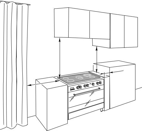
LOCATION
■■ The cooker can be installed in a cabinet (Fig. 1).
■■ The cooker must be installed no less than 50 mm away from any side wall which exceed the height of the cooktop.
■■ The appliance must be housed in heat resistant units.
■■ The walls of the units must be capable of resisting temperatures of 75 °C above room temperature.
■■ Do not install the appliance near inflammable materials (eg. curtains).
■■ If you stand the cooker on a pedestal, make sure you provide safety measures to keep it in place.
6
650 mm |
|
450 mm |
|
|
|
50 mm
500 mm
Cooker overall dimensions [mm]
■■ height: min 900 - max 925 Figure 1 ■■ width: 900
■■ depth: 600
7
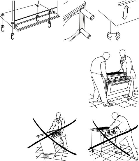
FITTING THE ADJUSTABLE FEET
The adjustable feet must be fitted to the base of the cooker before use (fig. 2).
Rest the rear of the cooker on a piece of the polystyrene packaging exposing the base for the fitting of the feet.
Fit the no. 4 (four) legs by screwing them tight into the support base as shown in figure 3.
LEVELLING THE COOKER
The cooker may be levelled by screwing the lower ends of the feet IN or OUT (fig. 4).
|
|
Figure 2 |
|
Figure 3 |
|
|
Figure 4 |
|||
|
|
|
|
|
|
|
|
|
|
|
|
|
|
|
|
|
|
|
|
|
|
|
|
|
|
|
|
|
|
|
|
|
|
|
|
|
|
|
|
|
|
|
|
|
|
|
|
|
|
|
|
|
|
|
|
|
|
|
|
|
|
|
|
|
|
|
|
|
|
|
|
|
|
|
|
|
|
|
|
|
|
|
|
|
|
|
|
|
|
|
|
|
|
|
|
|
|
|
|
|
|
|
|
|
|
|
|
|
|
|
|
|
|
|
|
|
|
|
|
|
|
|
|
|
|
|
|
|
|
|
|
MOVING THE COOKER |
Figure 5 |
WARNING: When raising cooker to upright |
|
position always ensure two people carry |
|
out this manoeuvre to prevent damage to |
|
the adjustable feet (fig. 5). |
|
WARNING - Be carefull: Do not lift the co- |
|
oker by the door handle when raising to the |
|
upright position (fig. 6). |
|
WARNING: When moving cooker to its fi- |
|
nal position DO NOT DRAG (fig. 7). Lift feet |
|
clear of floor (fig. 5). |
|
Figure 6 |
Figure 7 |
8
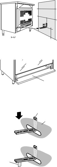
ANTI-TILT BRACKET
Important!
To restrain the appliance and prevent it tipping accidentally, fit a bracket to its rear to fix it securely to the wall. Make sure you also fit the supplied lock pin to the anti-tilt bracket.
To fit the anti-tilt bracket:
1.After you have located where the cooker is to be positioned, mark on the wall the place where the two screws
of the anti-tilt bracket have to be fitted.
Please follow the indications given in fig. 8.
2.Drill two 8 mm diameter holes in the wall and insert the plastic plugs supplied.
Important!
Before drilling the holes, check that you will not damage any pipes or electrical wires.
3.Loosely attach the anti-tilt bracket with the two screws supplied.
4.Move the cooker to the wall and adjust the height of the anti-tilt bracket so that it can engage in the slot on the cooker’s back, as shown in fig. 8.
5.Tighten the screws attaching the antitilt bracket.
6.Push the cooker against the wall so that the anti-tilt bracket is fully inserted in the slot on the cooker’s back.
7.Access the bracket and fit the lock pin: ■■ Open the pivoting panel (fig. 9).
■■ Fit the lock pin through the bracket, as shown (fig. 10).
■■ Close the pivoting panel.
Figure 8
0 
+25

Figure 9
900 mm
450 |
450 |
|
|
||
|
min 220 |
onfeet adjustment) |
|
max245 |
|
|
(depending |
|
Pivoting panel
Figure 10
1
Lock pin 
Anti-tilt bracket attached on the rear wall
Cooker’s back
Slot on the  cooker’s back
2
Lock pin correctly fitted
9
ELECTRICAL REQUIREMENTS
■■ The appliance must be connected to the mains checking that the voltage corresponds to the value given in the rating plate and that the electrical cable sections can withstand the load specified on the plate.
■■ A suitable disconnection switch must be incorporated in the permanent wiring, mounted and positioned to comply with the local wiring rules and regulations. The switch must be of an approved type installed in the fixed wiring and provide a 3 mm air gap contact separation in all poles in accordance with the local wiring rules.
In Australia and New Zealand, a switch of the approved type with a 3 mm air gap must be installed in the active (phase) conductor of the fixed wiring.
■■ The switch must always be accessible.
■■ The power supply cable must not touch the hot parts and must be positioned so that it does not exceed 75°C above ambient.
■■ To connect the cooker to the mains electricity supply, do not use adapters, reducers or branching devices as they can cause overheating and burning.
■■ This cooker must be connected to a suitable double pole control unit adjacent to the cooker. No diversity can be applied to this control unit.
■■ This cooker must be connected to electrical supply using V105 insulated cable.
In New Zealand, this appliance must be connected to the electrical supply using a cable fitted with an appropriately rated plug. The plug must be compatible with the socket-outlet fitted to the final subcircuit in the fixed wiring that is intended to supply the appliance.
■■ Once the appliance has been installed, the switch or socket must always be accessible.
■■ If the supply cord is damaged it must be replaced by the manufacturer or it’s Service
Agent or a similarly qualified person in order to avoid a hazard.
N.B. The connection of the appliance to earth is mandatory.
If the installation requires alterations to the domestic electrical system call a qualified electrician. He should also check that the domestic electrical system is suitable for the power drawn by the appliance.
Replacing the power cord must be done by a qualified electrician in accordance with the instructions supplied by the manufacturer and in compliance with established electrical regulations.
10
LOCATING THE AREA FOR ELECTRICAL CONNECTION
Dotted line showing the position of the cooker when installed
Area for ELECTRIC connection
max 290 mm
Figure 11
11
CONNECTION OF THE POWER SUPPLY CABLE
Important! This cooker must be connected to the electricity supply only by an authorised person.
To connect the feeder cable to the cooker it is necessary to:
•Remove the two screws that hold shield “A” behind the cooker (fig. 12).
•Open completely the cable clamp “D”.
•Fitted with a 6-pole terminal block, position the U bolts onto terminal block ‘B’ (fig. 12) according to the diagrams in figs. 13 - 14.
•Feed the supply cable through the cable clamp “D”. The supply cable must be of a suitable size for the current requirements of the appliance; see the section “Feeder cable section”.
•Connect the phase, neutral and earth wires to terminal “B” according to figures 13 and 14.
•Pull the feeder cable and block it with the cable clamp “D”.
•Re-mount shield “A”.
N.B. The earth conductor must be left about 3 cm longer than the others.
VOLTAGE AND POWER CONSUMPTION
230/400 V 3N~ |
50 Hz |
11800 W (51.30 A) (diversity not applied) |
240/415 V 3N~ |
50 Hz |
12800 W (53.33 A) (diversity not applied) |
FEEDER CABLE SECTION
This cooker must be connected to electrical supply using V105 insulated cable.
230 |
V~, 240 V~ |
3 x 6 mm2 |
(*) |
|
230 |
V 3~, 240 V~ |
4 x 4 mm2 |
(*) |
|
400 |
V 3N~, |
415 V 3N~ |
5 x 2,5 mm2 (*) |
|
400 V 2N~, |
415 V 2N~ |
4 x 4 mm2 |
(*) |
|
(* |
Connection with wall box connection. |
|||
––Diversity factor applied.
––A diversity factor may be applied to the total loading of the appliance only by a suitably qualified person.
12

|
|
|
|
|
|
|
|
|
|
|
|
|
Figure 12 |
|
|
|
|
Figure 13 |
|||
|
|
|
|
|
|
|
|
|
|
|
|
|
|
|
|
|
230 V~, 240 V~ |
|
|||
|
|
|
|
|
|
|
|
|
|
|
|
|
|
|
|
|
230 V~ |
|
|
||
|
|
|
|
|
|
|
|
|
|
|
|
|
B |
|
|
1 |
2 |
3 |
4 |
5 |
|
|
|
|
|
|
|
|
|
|
|
|
|
|
|
|
|
|
L1 |
|
N (L 2) |
PE |
|
|
|
|
D |
|
|
|
|
|
|
|
|
|
|
|
|
|
|
|
|
|
|
|
|
|
|
|
|
|
|
|
|
|
|
|
|
|
|
230 V 3~, 240 V 3~ |
|
||||
|
|
|
|
|
|
|
|
|
|
|
|
|
|
|
|
|
230 V 3~ |
|
|||
|
|
|
|
|
|
|
|
|
|
|
|
|
A |
|
|
1 |
2 |
3 |
4 |
5 |
|
1 |
2 |
3 |
4 |
5 |
|
|
|
|
|
1 |
2 |
3 |
4 |
5 |
|
|
L1 |
|
L2 |
L3 |
PE |
|
|
L1 |
|
N(L2) |
PE |
|
|
|
|
|
L1 |
|
L2 |
L3 |
PE |
|
|
||||
|
|
|
|
|
|
|
|
|
|
|
|
|
|
|
|
||||||
|
|
|
|
|
|
|
|
|
|
|
|
|
|
|
|
|
|
||||
|
|
230 V~ |
|
|
|
|
|
|
|
230 V 3~ |
|
|
|
|
|
|
|
||||
|
230 V~, 240 V~ |
|
|
|
|
230 V 3~, 240 V 3~ |
400 V 3N~, 415 V 3N~ |
||||||||||||||
|
|
|
|
|
|
|
|
|
|
|
|
|
|
|
|
||||||
|
|
|
|
|
|
|
|
|
|
|
|
|
|
|
|
400 V 3N~ |
|
||||
|
|
|
|
|
|
|
|
|
|
|
|
|
|
|
|
1 |
2 |
3 |
4 |
5 |
|
|
|
|
|
|
1 |
2 |
3 |
4 |
5 |
|
|
|
|
|
|
|
|
|
|
|
|
|
|
|
|
|
L1 |
L2 |
|
|
N |
|
PE |
|
|
|
|
|
|
|
|
|
|
|
|
|
|
|
|
|
|
|
|
|
|
|
|
|
|
|
|
|
|
|
|
|
|
|
|
|
|
|
|
|
|
|
|
|
|
|
|
L1 |
L2 |
L3 |
|
N |
PE |
|
|
|
|
|
|
400 V 2N~ |
|
|
|
|
|
|
|
|
|
|
|
|
|||
|
|
|
|
400 V 2N~, 415 V 2N~ |
|
|
|
|
|
|
|
|
|
|
|||||||
|
|
|
|
|
|
|
|
|
|
|
|
|
|
|
|
400 V 2N~, 415 V 2N~ |
|||||
|
|
|
|
|
|
|
|
|
|
|
|
|
|
|
|
|
400 V 2N~ |
|
|||
|
|
|
|
|
1 |
2 |
3 |
|
4 |
5 |
|
|
|
|
|
1 |
2 |
3 |
4 |
5 |
|
|
|
|
|
L1 |
L2 |
|
|
L3 |
|
N |
PE |
|
|
|
|
|
|
|
|
|
|
|
|
|
|
|
|
|
|
|
|
|
|
|
|
|
|
|
|
|
|
||
|
|
|
|
|
|
|
|
|
|
|
|
|
|
|
|
L1 |
|
L2 |
|
N |
PE |
Figure 14 |
|
400 V 3N~, 415 V 3N~ |
|
|
|
|
|
|
|
|
|
|
|||||||||
|
|
|
|
400 V 3N~ |
|
|
|
|
|
|
|
|
|
|
|
||||||
|
|
|
|
|
|
|
|
|
|
|
|
|
|
|
|
|
|
|
|
|
13 |
14
|
PR |
|
|
|
S2 |
|
|
|
|
|
|
|
1 |
S1 |
F1 |
TM |
|
|
|
|
|
|
|
|
|
|
F2 |
|
F3 |
|
|
|
|
|
|
|||
1a |
N/7 |
|
|
F4 |
F5 |
|
|
F6 |
||||
L/8 |
|
|
|
|
|
|
||||||
|
|
|
|
|
|
|
|
|
|
|
|
|
|
|
|
4 |
2 |
4 |
2 |
4 |
2 |
4 |
2 |
4 |
2 |
|
P3 |
|
P1 |
P1 |
P1 |
P1 |
P1 |
|||||
|
5 |
PILOT |
P2 |
PILOT |
P2 |
4a |
P2 |
4a |
P2 |
PILOT |
P2 |
|
|
|
|
||||||||||
|
P1 |
2 |
S2 |
S1 |
S2 |
S1 |
S2 |
S1 |
S2 |
S1 |
S2 |
S1 |
|
1 |
|||||||||||
|
|
|
|
|
|
|
|
|
|
|
|
|
|
P2 |
3 |
|
|
|
|
|
|
|
|
|
|
|
4 |
|
|
|
|
|
|
|
|
|
|
|
|
|
|
|
|
|
|
|
|
|
|
|
C |
LF |
|
|
|
|
|
|
2 S H |
4A |
|
|
2 S H |
|
4 |
|
||
4 |
|
S H P4 |
2 SH |
||
|
4 |
|
|||
|
2 SH |
|
|
|
|
G |
P1 |
P2 |
P3 |
2 |
4 |
4a |
|
||||
|
|
|
|
4 |
P5 |
V |
CF |
|
|
|
|
|
|
|
|
|
|
S |
|
|
|
CR |
|
TL
T
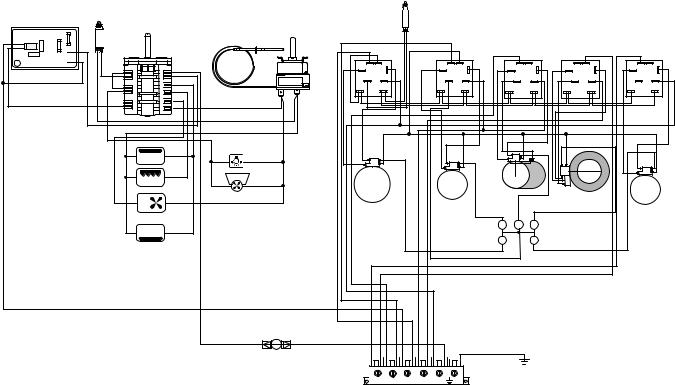
15Figure |
M 1 2 3 4 5 |
DIAGRAM ELECTRIC
 Loading...