


530F

Service Manual
Caution
: In this Manual, some parts can be changed for improving. their
performance without notice in the parts list. So, if you need the
latest parts information, please refer to PPL(Parts Price List)in
Service Information Center.
S/M No.TCP530FEF0
CHASSIS : CP-530FT/VT
CP-530/F
MODEL : DUX-21U7DT
DTU-28A8FZP
DUZ-29U7DT
DTU-29U7FZP
Dec. 2007

CP-530 Service Manual
-2-
CONTENTS
DOCUMENT HISTORY 4
1 MAIN FEATURES 5
1.1 SPECIFICATIONS 5
1.1.1 GENERAL 5
1.1.2 EURO-SCART 1 (21 Pin) 5
1.1.3 EURO-SCART 2 (21 Pin) 6
1.2 CHANNEL/FREQUENCY TABLE 7
2 SAFETY INSTRUCTION 9
3 ALIGNMENT INSTRUCTIONS 10
3.1 MICROCONTROLLER CONFIGURATION : SERVICE MODE 10
3.2 SERVICE MODE NAVIGATION 10
3.3 MICROCONTROLLER CONFIGURATION : OPTION BITS 10
3.4 OPTION 1 11
3.5 OPTION 2 11
3.6 NVM DEFAULT SETTING 12
3.7 TV SET ALIGNMENT 14
3.7.1 G2 ALIGNMENT 14
3.7.2 WHITE BALANCE 14
3.7.3 FOCUS 14
3.7.4 VERTICAL GEOMETRY 14
3.7.5 HORIZONTAL PICTURE CENTRING 14
3.7.6 EAST / WEST CORRECTION 14
4 IC DESCRIPTION 15
4.1 UOCTOP SERIES 15
4.1.1 IC MARKING AND VERSION 15
4.1.2 BLOCK DIAGRAM 16
4.1.3 PINNING 17
4.1.4 FEATURES 19
4.2 LA422XX STEREO AUDIO AMPLIFIER 21
4.2.1 FEATURES 21
4.2.2 BLOCK DIAGRAM AND PINNING 22
4.3 LA78040 VERTICAL AMPLIFIER 23
4.3.1 LA78040 23
4.4 TDA6107AJF 24
4.4.1 Features 24
4.4.2 Pin description 24
4.5 24WC16 -16 KB EEPROM 24
4.6 STR–W6754 26
4.6.1 GENERAL DESCRIPTION 26
4.6.2 FEATURES 26
4.6.3 BLOCK DIAGRAM 32

CP-530 Service Manual
-3-
4.6.4 PIN DESCRIPTION 27
4.6.5 CONTROL PART - ELECTRICAL CHARACTERISTICS 27
4.6.6 MOSFET ELECTRICAL CHARACTERISTICS 27
4.7 pnx831x 28
4.7.1 Pin list by numbers 28
4.7.2 Features 29
4.8 UDA1334BATS Audio Dac 31
4.8.1 Pinning 31
4.8.2 Features 31
4.9 CI MAX 32
4.9.1 Features 32
4.9.2 Pinning 33
4.10 M29W320ET (Fresh memory) 34
4.10.1 Features 34
4.10.2 Logic diagram and signal name 34
4.11 K4S281632D (SDRAM) 35
4.11.1 Features 35
4.11.2 Pin function 35
4.12 HEF4052(MULTIPLEXER) 36
4.12.1 PINNING AND FUNCTION TABLE 36
5 CIRCUIT DESCRIPTION 37
5.1 BLOCK DIAGRAM 37
6 SERVICE PARTS LIST 38
6.1 DUZ-29U7DT 38
6.2 DUX-21U7DT 48
7 EXPLODED VIEW 57
7.1 DUZ-29U7DT 57
7.2 DUX-21U7DT 58
8 PRINTED CIRCUIT BOARD 59
8.1 DUZ-29U7DT MAIN TOP 59
8.2 DUZ-29U7DT MAIN BOTTOM 60
8.3 DUX-21U7DT MAIN TOP 61
8.4 DUX-21U7DT MAIN BOTTOM 62
8.5 DTU-28A8FZP MAIN TOP 63
8.5 DTU-28A8FZP MAIN BOTTOM 64
8.5 DIGITAL BOARD/CRT PCB 65
9 SCHEMATIC DIAGRAM 66
9.1 CP-530FT 66
9.2 CP-530VT 67
9.3 CP-530 68
9.4 MAIN DIGITAL 69
Analog Backend 70
Common Inerface 71

CP-530 Service Manual
-4-
DOCUMENT HISTORY
VERSION DATE COMMENTS
V1.00 Creation of document (Author BD MIN) for project CP-530 50Hz iDTV.
/12/07
CP-530 Service Manual
-5-
MAIN FEATURES
1.1 SPECIFICATIONS
1.1.1 GENERAL
TV standard PAL - SECAM B/G D/K, PAL I/I, SECAM L/L’
Colour system Tuner PAL, SECAM
AV PAL, SECAM, PAL 60, NTSC M, NTSC 4.43
Sound system NICAM B/G, I, D/K, L,
FM 2Carrier B/G, D/K
Power
consumption
Sound Output Power 7W x 2 at 60% mod, 10%THD(4.5W x 2 21inch)
Speaker 12W 8 ohm x2
Teletext system 10 pages memory FASTEXT (FLOF or TOP)
Aerial input 75 ohm unbalanced
Channel coverage Off-air channels, S-cable channels and hyperband
Tuning system frequency synthesiser tuning system
Visual screen size
Channel indication On Screen Display
Program Selection 100 programmes
Aux. terminal
Remote Control R-52B02(CP-530FT/VT), R-49C10C(CP-530/F)
1.1.2 EURO-SCART 1 (21 Pin)
Pin Signal Description Matching value
1 Audio Output Right 0.5 Vrms, Impedance < 1 k , ( RF 60% Mod )
2 Audio Input Right 0.5 Vrms, Impedance > 10 k
3 Audio Output Left 0.5 Vrms, Impedance < 1 k , ( RF 60% Mod )
4 Audio Earth
5 Blue Earth
6 Audio Input Left 0.5 Vrms, Impedance > 10 k
0.7 Vpp – 0.1V, Impedance 75
7 Blue Input 0.7 Vpp
8
9
10
11
Slow Switching
Green Earth
N.C.
Green Input
TV : 0 to 2V, AV 16/9:4.5 to 7V, AV 4/3 : 9.5 to 12V, Impedance > 10 k
0.1V, Impedance 75
85W(CP-530FT), 74W(CP-530/F/VT)
EURO-SCART 1 : Audio / Video In/TV Out, R/G/B In, Slow and Fast switching.
EURO-SCART 2 : Audio / Video In/TV Out, YC In.
AV3 : Audio-Video Jack on front of cabinet.
S/VIDEO3 : Jack on front of cabinet — sound input common with AV3. (not in 21inch)
Headphone jack (3.5 mm) on front of cabinet

CP-530 Service Manual
-6-
1.1.3
EURO-SCART 2 (21 Pin)

CP-530 Service Manual
-7-
CHANNEL EUROPE CCIR FRANCE GB(IRELAND) EAST OIRT
C01 46.25 - 45.75 49.75
C02 48.25 55.75 (L ) 53.75 59.25
C03 55.25 60.5 (L ) 61.75 77.25
C04 62.25 63.75 (L ) 175.25 85.25
C05 175.25 176.00 183.25 93.25
C06 182.25 184.00 191.25 175.25
C07 189.25 192.00 199.25 183.25
C08 196.25 200.00 207.25 191.25
C09 203.25 208.00 215.25 199.25
C10 210.25 216.00 223.25 207.25
C11 217.25 189.25 (LUX) 231.25 215.25
C12 224.25 69.25 (L ) 239.25 223.25
C13 53.75 76.25 (L ) 247.25 -
C14 - 83.25 (L ) 49.75 -
C15 82.25 90.25 57.75 -
C16 - 97.25 65.75 -
C17 183.75 - 77.75 -
C18 192.25 - 85.75 -
C19 201.25 - - -
C20 - - - -
C21 471.25 471.25 471.25 471.25
C22 479.25 479.25 4 79.25 479.25
C23 487.25 487.25 487.25 487.25
C24 495.25 495.25 495.25 495.25
C25 503.25 503.25 503.25 503.25
C26 511.25 511.25 5 11.25 511.25
C27 519.25 519.25 519.25 519.25
C28 527.25 527.25 527.25 527.25
C29 535.25 535.25 535.25 535.25
C30 543.25 543.25 543.25 543.25
C31 551.25 551.25 551.25 551.25
C32 559.25 559.25 559.25 559.25
C33 567.25 567.25 567.25 567.25
C34 575.25 575.25 575.25 575.25
C35 583.25 583.25 583.25 583.25
C36 591.25 591.25 591.25 591.25
C37 599.25 599.25 599.25 599.25
C38 607.25 607.25 607.25 607.25
C39 615.25 615.25 615.25 615.25
C40 623.25 623.25 623.25 623.25
C41 631.25 631.25 631.25 631.25
C42 639.25 639.25 639.25 639.25
C43 647.25 647.25 647.25 647.25
C44 655.25 655.25 655.25 655.25
C45 663.25 663.25 663.25 663.25
C46 671.25 671.25 671.25 671.25
C47 679.25 679.25 679.25 679.25
C48 687.25 687.25 687.25 687.25
C49 695.25 695.25 695.25 695.25
C50 703.25 703.25 703.25 703.25
C51 711.25 711.25 711.25 711.25
C52 719.25 719.25 719.25 719.25
C53 727.25 727.25 727.25 727.25
C54 735.25 735.25 735.25 735.25
C55 743.25 743.25 743.25 743.25
C56 751.25 751.25 751.25 751.25
C57 759.25 759.25 759.25 759.25
C58 767.25 767.25 767.25 767.25
1.2 CHANNEL/FREQUENCY TABLE

CP-530 Service Manual
-8-
CHANNEL EUROPE CCIR FRANCE GB(IRELAND) EAST OIRT
C59 775.25 775.25 775.25 775.25
C60 783.25 783.25 783.25 783.25
C61 791.25 791.25 791.25 791.25
C62 799.25 799.25 799.25 799.25
C63 807.25 807.25 807.25 807.25
C64 815.25 815.25 815.25 815.25
C65 823.25 823.25 823.25 823.25
C66 831.25 831.25 831.25 831.25
C67 839.25 839.25 839.25 839.25
C68 847.25 847.25 847.25 847.25
C69 855.25 855.25 855.25 855.25
C70 863.25 863.25 863.25 863.25
C71 69.25 - - -
C72 76.25 - - -
C73 83.25 - - -
C74 90.25 - - -
C75 97.25 - - -
C76 59.25 - - -
C77 93.25 - - -
S01 105.25 104.75 103.25 105.25
S02 112.25 116.75 111.25 112.25
S03 119.25 128.75 119.25 119.25
S04 126.25 140.75 127.25 126.25
S05 133.25 152.75 135.25 133.25
S06 140.25 164.75 143.25 140.25
S07 147.25 176.75 151.25 147.25
S08 154.25 188.75 159.25 154.25
S09 161.25 200.75 167.25 161.25
S10 168.25 212.75 - 168.25
S11 231.25 224.75 - 231.25
S12 238.25 236.75 - 238.25
S13 245.25 248.75 255.25 245.25
S14 252.25 260.75 263.25 252.25
S15 259.25 272.75 271.25 259.25
S16 266.25 284.75 279.25 266.25
S17 273.25 296.75 287.25 273.25
S18 280.25 136.00 295.25 280.25
S19 287.25 160.00 303.25 287.25
S20 294.25 - - 294.25
S21 303.25 303.25 - 303.25
S22 311.25 311.25 311.25 311.25
S23 319.25 319.25 319.25 319.25
S24 327.25 327.25 327.25 327.25
S25 335.25 335.25 335.25 335.25
S26 343.25 343.25 343.25 343.25
S27 351.25 351.25 351.25 351.25
S28 359.25 359.25 359.25 359.25
S29 367.25 367.25 367.25 367.25
S30 375.25 375.25 375.25 375.25
S31 383.25 383.25 383.25 383.25
S32 391.25 391.25 391.25 391.25
S33 399.25 399.25 399.25 399.25
S34 407.25 407.25 407.25 407.25
S35 415.25 415.25 415.25 415.25
S36 423.25 423.25 423.25 423.25
S37 431.25 431.25 431.25 431.25
S38 439.25 439.25 439.25 439.25
S39 447.25 447.25 447.25 447.25
S40 455.25 455.25 455.25 455.25
S41 463.25 463.25 463.25 463.25

-9-
CP-530 Service Manual
2 SAFETY INSTRUCTION
W ARNING: Only competent service personnel may carry out work involving the testing or repair
of this equipment.
X-RAY RADIATION PRECAUTION
1. Excessive high voltage can produce potentially hazardous X-RAY RADIATION. To avoid
such hazards, the high voltage must not exceed the specified limit. The nominal value of the
high voltage of this receiver is 28-30 KV at max beam current. The high voltage must not,
under any circumstances, exceed 33 KV. Each time a receiver requires servicing, the high
voltage should be checked. It is important to use an accurate and reliable high voltage
meter.
2. The only source of X-RAY Radiation in this TV receiver is the picture tube. For continued X-
RAY RADIATION protection, the replacement tube must be exactly the same type tube as
specified in the parts list.
SAFETY PRECAUTION
Potentials of high voltage are present when this receiver is operating. Operation of the receiver
outside the cabinet or with the back board removed involves a shock hazard from the receiver.
Servicing should not be attempted by anyone who is not thoroughly familiar with the
precautions necessary when working on high voltage equipment.
Discharge the high potential of the picture tube before handling the tube. The picture tube is
highly evacuated and if broken, glass fragments will be violently expelled.
If any Fuse in this TV receiver is blown, replace it with the FUSE specified in the Replacement
Parts List.
When replacing a high wattage resistor (metal oxide film resistor) in the circuit board, keep the
resistor 10 mm away from circuit board.
Keep wires away from high voltage or high temperature components.
This receiver must operate under AC 220 - 240 volts, 50 Hz. NEVER connect to a DC supply or
any other voltage or frequency.
PRODUCT SAFETY NOTICE
Many electrical and mechanical parts in this equipment have special safety-related
characteristics. These characteristics are often passed unnoticed by a visual inspection and the
X-RAY RADIATION protection afforded by them cannot necessarily be obtained by using
replacement components rated for higher voltage, wattage, etc. Replacement parts which have
these special safety characteristics are identified in this manual and its supplements, electrical
components having such features are identified by designated symbol on the parts list. Before
replacing any of these components, read the parts list in this manual carefully. The use of
substitutes replacement parts which do not have the same safety characteristics as specified in
the parts list may create X-RAY Radiation.

-10-
CP-530 Service Manual
3 ALIGNMENT INSTRUCTIONS
3.1 MICROCONTROLLER CONFIGURATION : SERVICE MODE
To switch the TV set into service mode please see instruction below.
1 - Select PR. number 91
2 - Adjust sharpness to minimum and exit all menus.
3 - Within 2 seconds press the key sequence : RED - GREEN - menu
The software version is displayed beside the word Service, e.g. “SERVICE V0.22”.
To exit SERVICE menu press menu key or Stand By key.
3.2 SERVICE MODE NAVIGATION
Pr Up/Down remote keys : cycle through the service items available.
Vol -/+ remote keys : Dec./Increment the values within range - Cycle trough option bits.
OK key : Toggle bits in option byte
3.3 MICROCONTROLLER CONFIGURATION : OPTION BITS
There are two option bytes available (16 bits in all). These option bits are available from FACTORY and SERVICE
mode. First find the OPTION1 or OPTION2 control, and then use the UP/DOWN and PLUS/MINUS keys on
the relevant remote keypad to control the bits. The table below shows the two option bytes available;
-11-
CP-530 Service Manual
3.4 OPTION1
B7 B6 B5 B4 B3 B2 B1 B0
1
0
TOP
Teletext
OFF
FASTEXT
(FLOF)
OFF
TUBE
4:3
Dolby
Virtual
OFF
VAI bit set
to 1 in
SECAM L
TUNER OPTIONS
00 = Philips MK1
01 = Philips MK1 internal
AGC
10 = Philips MK3
11 = Philips MK3 internal
AGC
TOP
Teletext
ON
FASTEXT
(FLOF)
ON
TUBE
16:9
Dolby
Virtual
ON
SVHS3
auto
switch
enable
VAI bit set
to 0 in
SECAM L
3.5 OPTION2
B7 B6 B5 B4 B3 B2 B1 B0
1
0
Fixed to
‘0’
Fixed to
‘0’
n.u.
Must be
set to 1 for
future
compatibili
ty
5 keys
Iacal
keyboard
7 keys
Iacal
keyboard
Fixed to ‘1’
Digital
Analog
< CP-530F/FT OPTION BIT >
SVHS3
Auto
switch
disable
Full
ATSS
Basic
ATSS
SCALER
Enabled
SCALER
Disabled
B7
0
0
B6 B5 B4 B3 B2 B1
0 1 1 1 0 1
0 1 1 1 1 0
B1
1
0
3B
3D
OPTION1
OPTION2
< CP-530/VT OPTION BIT >
B7
0
0
B6 B5 B4 B3 B2 B1
0 1 1 1 1 1
0 1 1 1 1 0
B1
1
1
3F
3D
OPTION1
OPTION2

CP-530 Service Manual
-12-
3.6 NVM default setting
The purpose of this message, when you change a virgin EEPROM, is to allow to modify the
NVM DATA to desired values.
1 - Introduction :
The NVM default values are fixed for the user, but for flexibility in service, these data are stored
in NVM and can be changed when the TV set is in a special mode call “NVM EDITOR”. This
mode can only be access from “FACTORY”mode.
2 - Entering into
““
FACTORY
””
mode.
To switch the TV set into FACTORY mode, use the factory remote control, and press on “SVC”
key. The factory menu will appear on the screen, showing “FACTORY”, plus other relevant
information like software version and date.
WARNING : When in “FACTORY”mode you should not press any key other than the keys
described in the procedure below. Unwanted key stroke could misadjust the TV set.
3 - Entering into
““
NVM EDITOR
””
mode.
To switch the TV set into NVM EDITOR mode, use the user remote control, and press on “OK”
key. The NVM EDITOR window will appear on the screen. This mode allow you to access all
data stored in NVM. The current NVM address is given in column “ADDR.”in both DECimal
and HEXadecimal format. The column DATA gives the value contained at selected address in
both DECimal and HEXadecimal format.
4 - Navigation in
““
NVM EDITOR
””
mode.
Use Program Up/Down keys to select the desired address. Use Volume Up/Down keys to
change the data at selected address. You must press “OK ”key to store value after
modification.
The data can be adjusted between 0 and 63.
5 - Exit
““
NVM EDITOR
””
mode.
To switch the TV set back into FACTORY mode, use the user remote control, and press on
“MENU”key.
The factory menu will appear on the screen, showing “FACTORY”.
6 - Exit
““
FACTORY
””
mode.
To exit “FACTORY”mode, use the factory remote control, and press on “SVC”key.
The factory menu will disappear from the screen.

CP-530 Service Manual
-13-
NVM DATA CHANGE LIST CP-530F/FT CP-530VT
No Register Name Address DUZ-29U7DT DUX-21U7DT
1 OCP_THRESHOLD 0x58F 0x91 <-
2 DCXO 0x590 0x4E <-
3 AGC_PHILIPS 0x5C1 0xAB <-
4 AGC_NC 0x5C2 0x04 <-
5 AGC_ALPS 0x5C3 0XAB <-
6 AGC_PARTSNIC ËAGC DIGITAL 0x5C 0x30 0x30
7 AGC_PHILIPS_START 0x5C5 0x30 <-
8 AGC_NC_START 0x5C6 0x00 <-
9
AGC_ALPS_START 0x5C7 0x16
<-
10 AGC_PARTSNIC_START 0x5C8 0x00 <-
11 AVLLEV 0x621 0x5 <-
12
Nor1_Bright 0x64A 0x20
<-
13 Nor1_contrast 0x64B 0x36 0x36
14 Nor1_Colour 0x64C 0x20 0x20
15 Nor1_Sharpness 0x64D 0x20 <-
16 Nor1_Tint 0x64E 0x20 <-
17 Nor1_JVC_Bri 0x64F 0x2D <-
18 Nor1_JVC_Cont 0x650 0x2A <-
19 Nor1_JVC_Colour 0x651 0x1B <-
20 Nor1_JVC_Cont 0x650 0x2A <-
21 Nor2_Bright 0x653 0x28 <-
22 Nor2_Contrast 0x654 0x1C <-
23 Nor2_Colour 0x655 0x19 <-
24 Nor2_Sharpness 0x656 0x1B <-
25 Nor2_Tint 0x657 0x20 <-
26 PresetGainRGB 0x673 0x2A <-
27 PresetGainRGB 0x674 0x2A <-
28 PresetGainRGB 0x675 0x2A <-
29 Cathode_Drive 0x67B 0x3 0x3
30 Y_delay_PAL_BG 0x686 0x7 <-
31 Y_delay_SECAM_BG 0x687 0x7 <-
32 Y_delay_PAL_DK 0x688 0x7 <-
33 Y_delay_SCM_DK 0x689 0x7 <-
34 Y_delay_PAL_I 0x68A 0x9 <-
35 Y_delay_SECAM 0x68B 0x7 <-
36 Y_delay_SECAM-L 0x68C 0x8 <-
37 Y_delay_AV 0x68D 0x7 <-
38 G2_Bright 0x68E 0x2C 0x30
39 G2_Contrast 0x68F 0x42 <-
40 OSD_Bright 0x644 0x0C <-
41 TELETEXT OSD Bright 0x642 0x1C 0x1C
42 V-Lineartry 0x667 0x20 0x20
-14-
CP-530 Service Manual
3.7 TV SET ALIGNMENT
3.7.1 G2 ALIGNMENT
- Tune a colour bar pattern.
- Find the G2 - SCREEN item in service mode.
- Adjust screen volume ( on FBT ) to bring the cursor to central position : green.
3.7.2 WHITE BALANCE
- Select a dark picture and adjust RED BIAS and GRN BIAS to the desired colour temperature.
- Select a bright picture and adjust RED, GRN and BLUE GAIN to the desired colour temperature.
3.7.3 FOCUS
Adjust the Focus volume ( on FBT ) to have the best resolution on screen.
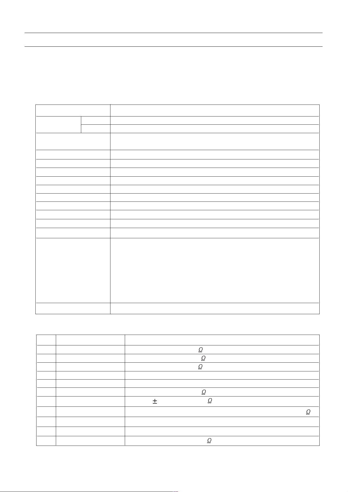
3.7.4 VERTICAL GEOMETRY
Adjust V. LINEAR (linearity), S CORRECT (S. Correction), VERT SIZE (Vertical amplitude), VERT CENT (vertical
centring) to compensate for vertical distortion.
3.7.5 HORIZONTAL PICTURE CENTRING
Adjust HOR CEN (Horizontal centre) to have the picture in the centre of the screen.
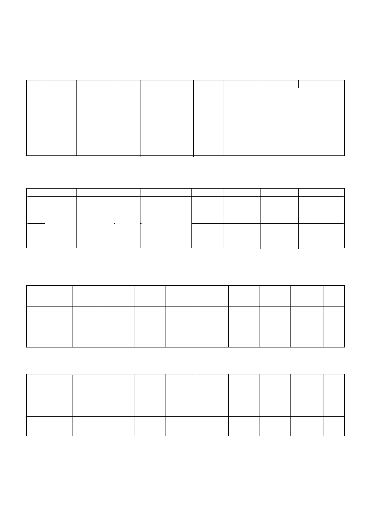
3.7.6 EAST / WEST CORRECTION
Adjust the PARABOLA, HOR WIDTH, CORNER, HOR PARAL, EW TRAPEZ, to compensate for geometrical
distortion.
HOR PARAL
-15-
CP-530 Service Manual
4 IC DESCRIPTION
4.1 UOCTOP Series
4.1.1 IC MARKING AND VERSION
The UOC-TOP-80 series is a very flexible concept which offers attractive solutions for 1fH TV receivers with CRTs.
This new concept offers a complete range of products with the right price level to cover TV receivers from basic
mono 14 inch sets up to the best featured large and/or wide screen stereo TV sets. The UOC-TOP-80 concept can
also be used as front-end for 2fH and LCD TV receivers.
• Stereo concept. It contains a video processor with many features and a micro controller with extensive OSD
possibilities (UOCTOP_10PTXTST version). Optional functions are a Teletext- /Closed Caption decoder, a digital
stereo decoder, an audio DSP.
• AV-110 (AV-stereo) concept. The features of the analog video processor are comparable with those of the Stereo
concept, but it has an analog audio control circuit with balance, treble, bass and loudness control. Two different
micro processor are available for this concept, one with OSD and Closed Captioning or Teletext and Closed
Captioning features (UOCTOP_1PTXT version), the other with (extended) OSD features (UOCTOP_OSD version).
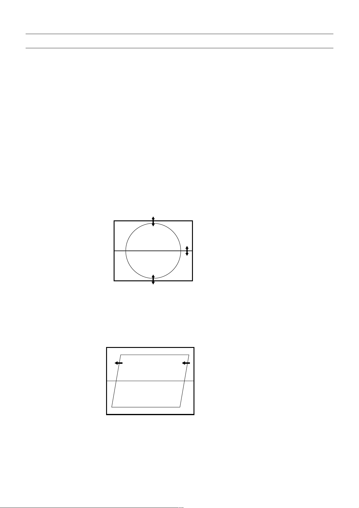
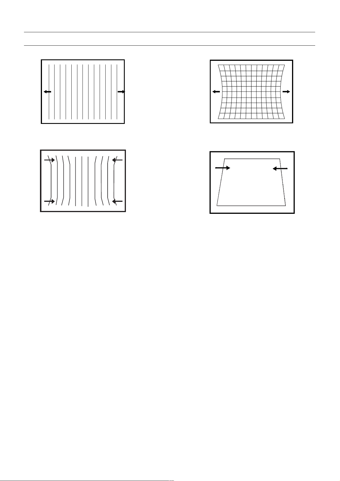
HOR WIDTH
adjust for 93% overscan.
PARABOLA
CORNER B & CORNER T
EW TRAPEZ
-16-
CP-530 Service Manual
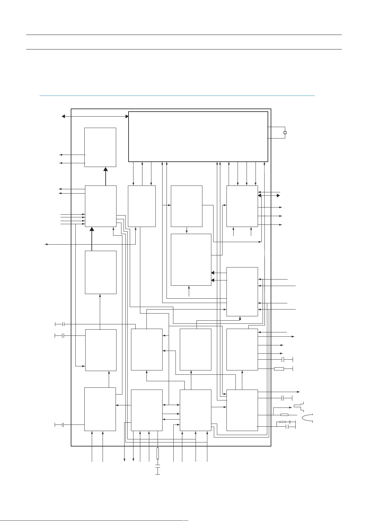
4.1.2. BLOCK DIAGRAM
NXP Semiconductors
UOC-TOP-80 N2 series
Signal processor for CRT TV
Fig 2.Block diagram of the “STEREO” TV processor
V-DRI VE
EW D
EHTO
QSS SOUND IF
VISION IF/AGC/AFC
PLL DEMOD.
VIDEO AMP.
SOUN D TRAP
GROU P DELAY
VIDEO SWITCH
VIDEO IDENT.
VIDEO FILTERS
DECOD ER
PAL/SECAM/NTSC
BASE-BAND
DELA Y LINE
H/V SYNC SEP.
H-OSC. + PLL
2
nd
LOOP
H-SHIFT
H-DRIVE
VERTICAL
GEOMET RY
& EAS T-WEST
AG COU T
VIFIN
C2/C3/C4/
CVBS4/Y 4
H-OUT
PEAKING
SCAN VELOCITY
RGB/YP
R
P
B
CON.
BRI
RO/ G O/BO/
BLKIN/
RGB CONTROL
OSD/TEXT INSERT
WHITE-P. ADJ.
CONTR/BRIGHTN
RGB MA TRIX
H/V
REF
Y DELAY ADJ.
SKIN TONE
U/V TINT
SATURATION
MODULATION
CVBS2/Y 2
YSY NC
IFVO/SVO /PIP
SOUN D PLL
R3/
G3/
B3/
INSW 3
YP
B
P
R
BLUE/BLACK-STRETCH
GA MMA C ONT ROL
BCLIN
CLK GENERATION
I
2
C-BUS
///
///
//
//
//
CSO
CSI
H/VDISPO
H/VD ISPI
CLKI
CLKO
IREFRGB
R/G/B
VD S
INS.
CIRN
CORB
SDA/SCL
IREF
IREFO
CVBSREF
CVBS IN
RESET
TMSE L
o
-PROC ESSOR / TELETEXT DECODE R / OSD
AM
AU DIO SELECT
SCART/CINCH
A/D CONVERTO R
ALL-STAN DA RD
SAT
VG UA RD/SWIO
STEREO
IN/OUT
P
R
-3/
Y-3
P
B
-3
QSS-MIXER
SWITCH
AU DIOIN5R
AU DIOIN5L
AUD IOIN5L
SVM
C2/C3/C4
CVB S3/
Y3
SIFIN
AG C
SIFAGC
AGC2SIF
AM DEMO DU LATOR
DECODE R
LS-OUT
L
R
AUD IO CONTROL
VOLUM E
TREBLE/BASS
FEATURES
DA Cs
I/Os
CCC/BLACK ADJ.

-17-
CP-530 Service Manual
4.1.3. PINNING
QFP 80 pin
1 VDDA(1.8V)
supply
2
3
VREFAD
GND5
reference voltage for audio ADCs (3.3/2 V)
ground
4
5
6
7
8
9
10
11
12
13
14
15
16
17
18
19
20
21
22
23
24
25
26
27
28
VDDA2(3.3V)
VDDA1(3.3V)
BO/PBOUT
GO/YOUT
RO/PROUT
BLKIN/SVM [1]
BCLIN
VP4
B3/PB3
G3/Y3/CVBS3/Y3 [1]
R3/PR3/C2/C3/C4 [1]
INSSW3/AUDIOIN5L [1]
YOUT
YSYNC
VP3
GND3
HOUT
FBISO/SANDCA
EHTO
AUDOUTSR
AUDOUTSL
AUDOUTLSR
AUDOUTLSL
C2/C3/C4/AUDIOIN5R [1]
AUDIOIN2R
supply
supply voltage
Blue output / PB output
Green output / Y output
Red output / PR output
black current input / scan velocity modulation output
beam current limiter input
supply for TV processor
3rd B input/Pb input
3rd G input / Y input / CVBS input / Y input
3rd R input / PR input / C2/3/4 input
3rd RGB / YPBPR insertion input / audio 5 left input
Y-output (for YUV interface)
Y-input for sync separator
supply voltage (5 V)
ground connection
horizontal output
flyback input/sandcastle output
EHT/overvoltage protection input
audio output for SCART/CINCH (right signal)
audio output for SCART/CINCH (left signal)
audio output for audio power amplifier (right signal)
audio output for audio power amplifier (left signal)
chroma-2/3/4 input / audio 5 right input
right stereo 2 input
SYMBOL DESCRIPTION

-18-
CP-530 Service Manual
QFP 80 pin
29 CVBS2/Y2
CVBS2/Y2 input
30
31
AUDIOIN2L/SSIF
CVBS4/Y4/AUDIOIN5L [1]
left stereo input / sound IF input
CVBS4/Y4 input audio 5 left input
32
33
34
35
36
37
38
39
40
41
42
43
44
45
46
47
48
49
50
51
52
53
54
55
56
57
AUDIOIN4R
AUDIOIN4L
IFVO/SVO/PIP [4]
VP2
AGC2SIF
PLLIF
GND2
SIFAGC
AGCOUT
SIFIN2
SIFIN1
IREF
VSC
VIFIN2
VIFIN1
VDRA
VDRB
EWD
DECBG
SECPLL
GND1
PH1LF
PH2LF
VP1
DECDIG
VGUARD/SWIO [6]
audio-4 input (right signal)
audio-4 input (left signal)
IF video output / selected CVBS output / PIP output
2nd supply voltage TV processor (+5 V)
Sound IF AGC capacitor
IF-PLL loop filter
ground 2 for TV processor
Sound IF AGC capacitor
tuner AGC output
2nd sound IF input
1st sound IF input
reference current input
vertical sawtooth capacitor
IF input 2
IF input 1
vertical drive A output
vertical drive B output
East-West drive output
bandgap decoupling
SECAM PLL decoupling
ground 1 for TV-processor
phase-1 filter
phase-2 filter
1st supply voltage TV-processor (+5 V)
decoupling digital supply
V-guard input / I/O switch (e.g. 4 mA current sinking
capability for direct drive of LEDs)
SYMBOL DESCRIPTION
CP-530 Service Manual
-19-
QFP 80 pin
58 DECDIGNEG
supply
59
60
XTALOUT
XTALIN
crystal oscillator output
crystal oscillator input
61
62
63
64
65
66
67
68
69
70
71
72
73
74
75
76
77
78
79
80
SNDNEG
VDDA3(3.3V)
P1.2
P2.5/PWM4
P2.4/PWM3
P3.3/ADC3
P3.2/ADC2
VDDC(1.8V)
P3.1/ADC1
P3.0/ADC0
P2.3/PWM2
P2.2/PWM1
P2.1/PWM0
P2.0/TPWM
VDDP(3.3V)
P1.7/SDA
P1.6/SCL
P1.3/T1
NT0/P0.5
P1.0/INT1
supply
supply
port 1.2
port 2.5 or PWM4 output
port 2.4 or PWM3 output
port 3.3 or ADC3 input
port 3.2 or ADC2 input
supply
port 3.1 or ADC1 input
port 3.0 or ADC0 input
port 2.3 or PWM2 output
port 2.2 or PWM1 output
port 2.1 or PWM0 output
port 2.0 or Tuning PWM output
supply to periphery (3.3V)
port 1.7 or I2C-bus data line
port 1.6 or I2C-bus clock line
port 1.3 or Counter/Timer 1 input
external interrupt 0 or port 0.5 (4 mA current
sinkingcapability for direct drive of LEDs)
port 1.0 or external interrupt 1
SYMBOL DESCRIPTION
4.1.4 FEATURES
Video / Audio Processing (AV-110/90 and Mono-110/90 concept)
# Overview of available features (AV-110/90 and Mono-110 concept)
· Multi-standard vision IF circuit with alignment-free PLL demodulator
· Internal (switchable) time-constant for the IF-AGC circuit
· Switchable group delay correction and sound trap (with switchable centre frequency) for the
demodulated CVBS signal

CP-530 Service Manual
-20-
· Separate Second Sound IF output or FM demodulator output without de-emphasis available,
which can be used as input for an external BTSC decoder or as input for external sound
band-pass filter for second language processing.
· Separate SSIF input available as input for the FM-PLL demodulator to demodulate FM-radio
with an IF frequency of 10.7 MHz, or as input from an external sound band-pass filter for
second language processing.
· AM demodulator without extra reference circuit
· The mono intercarrier sound circuit has a selective FM-PLL demodulator which can be
switched to the different FM sound frequencies (4.5/5.5/6.0/6.5 MHz). The quality of this
system is such that the external band-pass filters can be omitted.
·The FM-PLL demodulator can be set to centre frequencies of 4.72/5.74 MHz so that a
second sound channel can be demodulated. In such an application it is necessary that an
external bandpass filter is inserted.
· Audio switch circuit with 3 stereo inputs (1 stereo input can also be switched into two mono
sound inputs), a stereo output for SCART/CINCH with the possibility to serve as front/monitor
audio output and a stereo output (with volume and tone-control), for audio power amplifiers.
The third stereo input is only available via the combined C2/C3/C4/AUDIOIN5R pin for the
right channel and via the combined CVBS4/Y4/AUDIOIN5L pin or INSSW3/AUDIOIN5L pin,
for the left channel.
· Video switch with 3 external CVBS inputs. All CVBS inputs can be used as Y-input for Y/C
signals. However, only 1 Y/C source can be selected because the circuit has 1 chroma input.
CVBS3/Y3 input available in combination with the G/Y-3 input pin.
·1 CVBS output, this output can be used as monitor video output or as front-end video output
or as independent selectable video output.
· Automatic Y/C signal detector.
· Integrated luminance delay line with adjustable delay time.
· Only one reference (24.576 MHz) crystal required for the m-Controller, Teletext- andthe color
decoder
· Multi-standard color decoder with automatic search system and various “forced mode”
possibilities
·
Internal base-band delay line.
· Indication of the Signal-to-Noise ratio of the incoming CVBS signal
· Linear RGB/YPBPR input with fast insertion.
· Scan Velocity Modulation output. The SVM circuit is active for all the incoming CVBS,Y/C
and RGB/YPBPR signals. The SVM output is combined with the black current input of the
black current stabilisation circuit. By means of a small application adaptation both functions
can be operational in parallel. Picture improvement features with peaking (with switchable
centre frequency, depeaking, variable positive/negative peak ratio, variable pre-/overshoot
ratio and video dependent coring), dynamic skin tone control, gamma control and blue- and
black stretching. All features are available for CVBS, Y/C and RGB/YPBPR signals
· The effect of the various features can de demonstrated by means of a ‘split screen’ mode in
which the features are activated in one half of the picture and switched off in the other half
· Switchable DC transfer ratio for the luminance signal
· Tint control for external RGB/YPBPR signals
· Contrast reduction possibility during mixed-mode of OSD and Text signals. Option to make

CP-530 Service Manual
-21-
a colored and in contrast reduced window.
· RGB control circuit with ‘Continuous Cathode Calibration’, white point and black level off-set
adjustment so that the color temperature of the dark and the light parts of the screen can be
chosen independently. When this ‘Continuous Cathode Calibration’ is not used, simple
alignment of the cutoff level is possible.
· Adjustable ‘wide blanking’ of the RGB outputs
· Horizontal synchronization with two control loops and alignment-free horizontal oscillator
· Vertical count-down circuit
· Vertical driver optimized for DC-coupled vertical output stages
· Horizontal and vertical geometry processing with horizontal parallelogram and bow
correction and horizontal and vertical zoom
· The IC can be used as front-end for Progressive Scan or LCD TV receivers.
· Low-power start-up of the horizontal drive circuit
4.2 LA422XX STEREO AUDIO AMPLIFIER
SP series (Sanyo audio Power new series) is audio power IC which made Pin compatible
possible altogether in 3 to 15W.
The LA422XX is 2ch BTL audio power amplifier for TV application.
The SP series is included the pure complementary PNP and NPN Transistor output stage.
4.2.1 FEATURES
· Po 10W x 2ch (VCC=11.5V,RL=8É∂,THD=10%)
· Built–in Standby and Mute function.
· Full complement of built-in protection circuits
(Protection from shorting to ground, shorting to VCC,load shorting, and overheating.)

CP-530 Service Manual
-22-
4.2.2 Black diagram and Pinning
 Loading...