


www.rtv-horvat-dj.hr
for professional technicians
INTRODUCTION OF NEW ACCESS ARRANGEMENTS
BACK
RTV servis HORVAT supplies service information documents, in PDF format, for a wide range of electronic equipment, both consumer and professional.
Existing customers will know that, previously, service documents had to be specifically requested by exchange of emails, to be subsequently downloaded from an address we would notify to you. This was a cumbersome procedure, and we have now introduced a new system to allow you to directly access our database, and to immediately download the documents you require. Individual documents may be selected for download as required, and we also offer CD image packs containing a selection of documents covering related or popular equipment models.
You may register for periods covering six months or one year, which will entitle you to download specific numbers of documents, as follows:
1.Membership 30 days, 10 documents maximum - 15 EURO
2.Membership 6 months, 600 documents maximum - 65 EURO
3.Membership 12 months, 1200 documents maximum - 125 EURO
Our new document access service is based on INTERBASE server software, which we provide for your use, and which must be downloaded and installed on your own system.
BUT – IF YOU ARE ALREADY AN INTERBASE USER, WITH AN EXISTING INTERBASE
INSTALLATION, YOU SHOULD NOT ATTEMPT TO LOAD OUR SOFTWARE WITHOUT
FIRST CONTACTING US FOR ADVICE.
You must also note that this first release of our new system must be installed on a machine with a direct connection to the internet for downloading. The new software will function over your local network, you have to install our remotebrowser.exe on your local machines. For this software, contact us.
For the installation:
1. You must download the two application programs you will need:
Interbase Server.exe
rtvhdemosetup.exe
2.First install Interbase, restart the computer, then install rtvhdemosetup.exe.
3.You will now have a working but unregistered version of our system and will be able to download and open the demo PDF documents which have permissions already embedded in the Demo software you have downloaded and installed, but no others. To see these demo documents:
3.1Launch (run) the RTV-HORVAT program.
3.2Click on the Search tab.
3.3Click in the box titled ‘Show Documents With Permission Only’.
3.4Select a document by clicking on the adjacent ‘+’ button, connect to the internet and then clicking the ‘Download’ button above the list.
3.5The document will be downloaded, and when received can be viewed via the ‘View Document’ button.
3.6Note that you can only view the downloaded RTV PDF files via the RTV software, using the Search and View procedure described above. If you attempt to open an RTV PDF file directly from the RTV download folder, then the Acrobat reader will open, but display of the file will be denied.
3.7For more detailed information about facilities and use of the RTV-HORVAT system, please consult the information available via the ‘INFORMATION’ tab in the program display.
4.Please download a few of the sample documents to which we have provided immediate access.
5.If everything works OK, and you wish to register for our service, then please follow the instructions in para 10 (Registration Process) given under the program ‘INFORMATION’ tab.
We do not think you will find any major problems with this software, and will be grateful for your forbearance for anything that does arise.
Regards
Marijan
BACK

S/N No. :
Service Manual
Mini Component System
Model: AMI-V225M
AMI-V325M
www.rtvDAEWOO-horvatELECTRONICS-dj.hr CO., LTD.
http : //svc.dwe.co.kr |
Sep. 2002 |

 TABLE OF CONTENTS
SAFETY PRECAUTIONS.................................................................................................................... |
2 |
ADJUSTMENTS ................................................................................................................................. |
4 |
EXPLODED VIEW AND PARTS LIST ................................................................................................ |
5 |
WIRING DIAGRAM ............................................................................................................................. |
7 |
BLOCK DIAGRAM .............................................................................................................................. |
8 |
SCHEMATIC DIAGRAM ..................................................................................................................... |
9 |
POWER / AMP .................................................................................................................................................................. |
9 |
C D ...................................................................................................................................................................................... |
10 |
TUNER .............................................................................................................................................................................. |
11 |
TAPE ................................................................................................................................................................................ |
12 |
CONTROL ......................................................................................................................................................................... |
13 |
PCB PATTERN LAYOUT .................................................................................................................... |
14 |
ELECTRICAL PARTS LIST.................................................................................................................. |
16 |
www.rtv-horvat-dj.hr
- 1 -
Safety Precautions
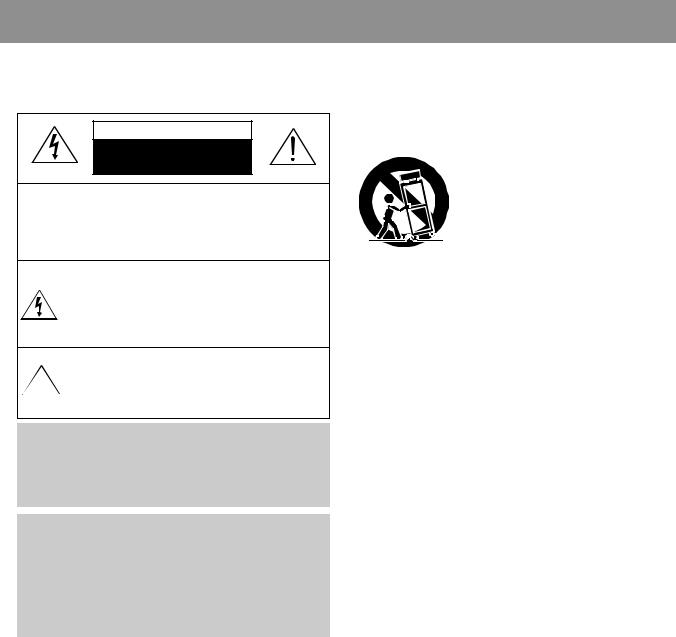
WARNING: TO PREVENT FIRE OR ELECTRIC SHOCK, DO NOT EXPOSE THIS APPLIANCE TO RAIN OR MOISTURE.
CAUTION
RISK OF ELECTRIC SHOCKS
DO NOT OPEN
CAUTION :TO REDUCE THE RISK IF ELECTRIC SHOCK, DO NOT REMOVE COVER (OR BACK). NO USER SERVICEABLE PARTS INSIDE.
REFER SERVICING TO QUALIFIED SERVICE PERSONNEL.
THIS SYMBOL IS INTENDED TO ALERT THE USER TO THE PRESENCE OF UNINSULTED "DANGEROUS VOLTAGE" WITHIN THE PRODUCT'S ENCLOSURE THAT MAY BE SUFFICIENT MAGNITUDE TO CONSTITUTE A RISK OF ELECTRIC SHOCK TO PERSONS.
THIS SYMBOL IS INTENDED TO ALERT THE USER TO THE  PRESENCE OF IMPORTANT OPERATING AND MAINTENANCE
  (SERVICING) INSTRUCTIONS IN THE LITERATURE ACCOMPANYING THE APPLIANCE.
CAUTION
TO PREVENT ELECTRIC SHOCK, DO NOT USE THIS POLARIZED AC PLUG WITH AN EXTENSION CORD, RECEPTACLE OR OTHER OUTLET UNLESS THE BLADES CAN BE FULLY INSERTED TO PREVENT BLADE EXPOSURE.
LASER SAFETY
THIS UNIT EMPLOYS A LASER. ONLY QUALIFIED SERVICE PERSONNEL SHOULD REMOVE THE COVER OR ATTEMPT TO SERVICE THIS DEVICE DUE TO POSSIBLE EYE INJURY.
CAUTION : USE OF ANY CONTROLS, ADJUSTMENTS, OR PROCEDURES OTHER THAN THOSE SPECIFIED HEREIN MAY RESULT IN HAZARDOUS RADIATION EXPOSURE.
CAUTION : TO PREVENT ELECTRIC SHOCK, MATCH WIDE BLADE OF PLUG TO WIDE SLOT, FULLY INSERT.
ATTENTION : POUR EVITER LES CHOCS ELECTRIQUES, INTRODUIRE LA LAME LA PLUS LARGE DE LA FICHE DANS LA BORNE CORRESPONDANTE DE LA PRISE ET POUSSER JUSQU'AU FOND.
Important Safety Instructions
-All the safety and operating instructions should be read before the appliance is operated.
-The safety and operating instructions should be retained for future reference.
-All warnings on the appliance and in the operating instructions should be adhered to.
-All operating and use instructions should be followed.
1.Water and Moisture - The appliance should not be used near water - for example, near a bathtub, washbowl, kitchen sink,
laundry tub, in a wet basement, or near a swimming pool, and the like.
2. Carts and Stands - The appliance should be used only with a cart or stand that is recommended by th manufacturer.
3. An appliance and cart combination
should be moved with care. Quick
stops, excessive force, and uneven surfaces may cause the appliance and cart combination to overturn.
4. Wall or Ceiling Mounting - The appliance should be mounted to a wall or
ceiling only as recommended by the manufacturer.
5.Ventilation - The appliance should be situated so that its location or position does not interfere with its proper ventilation. For example, the appliance should not be situated on a bed, sofa, rug, or similar surface that may block the ventilation openings; or, placed in a built-in installation, such as a bookcase or cabinet that may impede the flow of air through the ventilation openings.
6.Heat - The appliance should be situated away from heat sources such as radiators, heat registers, stoves, or other appliances (including amplifiers) that produce heat.
7.Power Sources - The appliance should be connected to a power supply only of the type described in the operating instructions or as marked on the appliance.
8.Grounding or Polarization - The precautions that should be taken so that the grounding or polarization means of an appliance is not defeated.
9.Power - Cord Protection - Power-supply cords should be routed so that they are not likely to be walked on or pinched by items placed upon or against them, paying particular attention to cords at plugs, convenience receptacles, and the
point where they exit from the appliance.
10.Protective Attachment Plug - If the appliance is equipped with an attachment plug having overload protection. This is a safety feature. See Instruction Manual for replacement or resetting of protective device. If replacement of the plug is required, be sure the service technician has used a replacement plug specified by the manufacturer that has the same overload protection as the original plug.
11.Cleaning - The appliance should be cleaned only as recommended by the manufacturer.
12.Power Lines - An outdoor antenna should be located away from power lines.
www.rtv-horvat-dj.hr
- 2 -
Safety Precautions
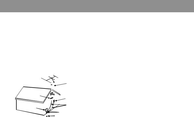
13.Outdoor Antenna Grounding - If an outside antenna is connected to the receiver be sure the antenna system is grounded so as to provide some protection against voltage surges and built-up static charges. Article 810 of the National Electrical Code, ANSI/NFPA 70, provides information with regard to proper grounding of the mast and supporting structure, grounding of the lead-in wire to an antenna-dis charge unit, size of grounding conductors,location of antennadischarge unit, connection to grounding electrodes and requirements for the grounding electrode. See Figure 1.
EXAMPLE OF ANTENNA |
|
|
|
|
|
|
|
|
|
|
GROUNDING |
|
|
|
|
|
|
|
|
|
ANTENNA LEAD |
|
|
|
|
|
|
|
|
|
||
GROUND CLAMP |
|
|
|
|
|
|
|
|
|
IN WIRE |
|
|
|
|
|
|
|
|
|
||
|
|
|
|
|
|
|
|
|
|
|
|
|
|
|
|
|
|
|
|
|
|
|
|
|
|
|
|
|
|
|
|
|
|
|
|
|
|
|
|
|
|
|
ANTENNA DISCHARGE UNIT |
|
|
|
|
|
|
|
|
|
|
|
|
|
|
|
|
|
|
|
|
|
(NEC SECTION 810-20) |
ELECTRIC |
|
|
|
|
|
|
|
|
|
GROUNDING CONDUCTORS |
|
|
|
|
|
|
|
|
|
||
|
|
|
|
|
|
|
|
|
(NEC SECTION 810-21) |
|
SERVICE |
|
|
|
|
|
|
|
|
|
|
EQUIPMENT |
|
|
|
|
|
|
|
|
|
GROUND CLAMPS |
|
|
|
|
|
|
|
|
|
|
|
|
|
|
|
|
|
|
|
|
POWER SERVICE GROUNDING |
|
|
|
|||||||||
|
|
|
|
|
|
|
|
|
||
|
|
|
|
|
|
|
|
|
ELECTRODE SYSTEM |
|
NEC - NATIONAL ELECTRICAL CODE |
|
|
|
|
|
|
|
|
(NEC ART 250 PART H) |
|
14.Non-use Periods - The power cord of the appliance should be unplugged from the outlet when left unused for a long period of time.
15.Object and Liquid Entry - Care should be taken so that objects do not fall and liquids are not spilled into the enclosure through openings.
16.Damage Requiring Service - The appliance should be serviced by qualified service personnel when:
a)The power-supply cord or the plug has been damaged; or
b)Objects have fallen, or liquid has been spilled into the appliance; or
c)The appliance has been exposed to rain; or
d)The appliance does not appear to operate normally or exhibits a marked change in performance; or
e)The appliance has been dropped, or the enclosure damaged.
17.Servicing - The user should not attempt to service the appliance beyond that described in the operating instructions. All other servicing should be referred to qualified service personnel.
www.rtv-horvat-dj.hr
- 3 -
Adjustments
TAPE SECTION
Output Level |
|
|
Measurement |
Input Point |
Scope |
Point |
|
|
R-CH |
47 kohm |
|
|
|
|
Input Level |
VTVM |
|
|
|
|
Measurement |
|
|
Point |
|
|
L-CH |
47 kohm |
|
|
|
Test Tape be used
Tape |
Contents |
Use |
MTT-111N |
3 KHz |
Tape Speed Adjustment |
MTT-114N |
10 KHz |
Head Azimuth Adjustment |
MTT-5511 |
Blank |
Record Frequency Property |
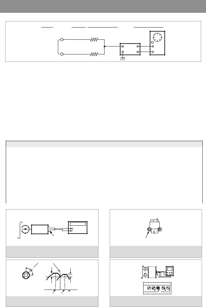
HEAD ADJUSTMENT (AZIMUTH)
1.10KHz test tape(example: MTT-114N) must be used for this adjustment.
2.Connect to VTVM or oscilloscope to the headphone jack or speaker terminal.
3.Press the play button.
4.Adjust the azimuth by using a screw driver to maintain the max. L&R output voltage.
5.Adjust tape A(1), tape B(2) respectively, Please secure the azimuth position by using locking paint.
RECORDING BIAS OSCILLATOR FREQUENCY ADJUSTMENT
1.Connect the frequency counter to TP603, GND.
2.Press the REC button.
3.Adjust L603 to obtain 80 KHz±100Hz
TAPE ALIGNMENT CHART
Step |
Item |
|
Reference Value |
Test Tape |
Adjust Point |
Test Point |
Note |
FIG. |
|
|
|
|
3,015~3,025Hz |
MTT-111N |
RV601 |
Line Out L/R |
Confirm Wow & Flut- |
FIG.1 |
|
|
Tape Speed |
|
Channel |
ter is within 0.35% |
|||||
|
Normal |
|
|
|
|
Confirm Tape Speed |
|
||
|
Adjustment |
|
|
|
Line Out L/R |
|
|||
1 |
|
|
3,000~3,010Hz |
MTT-111N |
RV601 |
of end position after |
FIG.1 |
||
|
|
Channel |
adjustment at tape |
||||||
|
|
|
|
|
|
|
start position |
|
|
|
|
|
|
|
|
|
|
|
|
2 |
Azimuth Adjustment |
Maximum Level |
MTT-114N |
Head Screw |
Line Out L/R |
|
FIG.2,3,4 |
||
Phase:Within90° |
Channel |
|
|||||||
|
|
|
|
|
|
|
|||
|
Recording Bias Oscilla- |
|
|
|
TP603,GND |
Adjust with frequency |
|
||
3 |
tor Frequency Adjust- |
80 KHz±0.5 |
MTT-5511 |
L603 |
counter connected. |
FIG.1 |
|||
|
|||||||||
|
ment |
|
|
|
|
|
|
|
|
|
|
Adjust with Frequency |
Test Tape : MTT-111N(3kHz) |
|
Counter Connected |
Frequency Counter |
|
|
MTT-5511(Blank) |
|
|
|
|
|
Set |
|
|
|
Output Level |
|
|
Measurement Point |
Forward |
|
|
Side |
FIG. 1 : Tape Speed & Record Bias Oscillator |
FIG. 2 : Tape Azimuth Adjust Location |
|
Frequency Adjust Circuit |
(Record/Playback Head) |
|
L-CH
Peak 
R-CH
Peak
Screw
Angle
Output Level
within 1 dB
within 1 dB
L-CH |
R-CH |
|
Screw Angle |
Peak |
Peak |
|
|
MTT-114N |
|
|
(10kHz) |
Oscilloscope |
|
L-CH |
||
Set |
V |
H |
|
|
|
|
Output Level |
|
|
Measurement Point |
|
|
Screen Pattern |
|
||
In Phase |
45 |
90 |
135 |
180 |
Good |
|
Wrong |
||
FIG. 3 : Tape Azimuth Adjust Head Screw & Waveform |
FIG. 4 : Tape Azimuth Adjust Circuit & Waveform |
www.rtv- |
horvat-dj.hr |
- 4 -

EXPLODED VIEW AND PARTS LIST
1. AMI-V225M/V325M
hr.dj-horvat-rtv.www
- 5 -
 Loading...