


Owner's Manual
®
46"- 2 STAGE SNOW THROWER
TRACTOR ATTACHMENT
Model No. 486.248463
CAUTION:
Before using this product, read this manual and follow all Safety
Rules and
Operating Instructions.
IMPORTANT - READ THIS FIRST!!!
For Missing Parts or Assembly Questions Please Call 866-576-8388
Mon.-Fri. 7 am - 5 pm CST.
FAX 217-728-2032 or e-mail info@agri-fab.com
Missing parts will be sent UPS in 24 hours directly to your home.
Sears, Roebuck and Co., Hoffman Estates, IL 60179 U.S.A. www.sears.com/craftsman
•Safety
•Assembly
•Operation
•Maintenance
•Parts
PRINTED IN U.S.A. |
FORM NO. 49788 (REV. 7/05) |
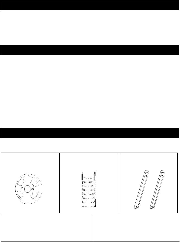
TABLE OF CONTENTS
ACCESSORIES |
2 |
SERVICE AND ADJUSTMENTS |
18 |
SAFETY RULES |
3 |
STORAGE |
19 |
FULL SIZE HARDWARE CHART |
4 |
TROUBLESHOOTING |
19 |
CARTON CONTENTS |
5 |
REPAIR PARTS ILLUSTRATION |
20,22 |
ASSEMBLY |
6 |
REPAIR PARTS LIST |
21,23 |
OPERATION |
15 |
SLOPE GUIDE |
27 |
MAINTENANCE |
17 |
PARTS ORDERING/SERVICE |
Back Page |
WARRANTY
LIMITED ONE YEAR WARRANTY ON 46" 2-STAGE SNOW THROWER
For one year from the date of purchase, when this snow thrower is maintained and lubricated according to the operating and maintenance instructions in the owner's manual, Sears will repair any defect in material or workmanship free of charge. If this snow thrower is used for commercial or rental purposes, this warranty applies for only 90 days from the date of purchase.
This warranty does not cover repairs necessary because of operator negligence or abuse, including the failure to maintain the equipment according to instructions contained in the owner's manual.
WARRANTY SERVICE IS AVAILABLE BY CONTACTING THE NEAREST SEARS SERVICE CENTER/DEPARTMENT IN THE UNITED STATES.
This warranty applies only while this product is in the United States.
This warranty gives you specifi c legal rights, and you may also have other rights which vary from state to state.
Sears, Roebuck and Co. D/817 WA. Hoffman Estates, Chicago, IL 60179
ACCESSORIES AND ATTACHMENTS
These accessories were available when the unit was purchased.They are also available at most Sears retail outlets and service centers. Most Sears stores can order repair parts for you when you provide the model numbers of your tractor and snow thrower.
WHEEL WEIGHT |
TIRE CHAINS |
DRIFT CUTTER BARS |
|
|
KIT NO. 71-52050 |
The model number and serial numbers will be found on a decal attached to the snow thrower.
You should record both the serial number and the date of purchase and keep in a safe place for future reference.
MODEL NUMBER: |
486.248463 |
SERIAL NUMBER: |
__________________ |
DATE OF PURCHASE: |
__________________ |
2

SAFETY
Anypowerequipmentcancauseinjuryifoperatedimproperlyoriftheuserdoesnotunderstandhowtooperatetheequipment.
Exercise caution at all times, when using power equipment.
•Read this owner's manual carefully and know how to operate your snow thrower and how to stop the unit and disengage the controls quickly.
•Never allow children to operate the equipment.
•Never allow adults to operate the equipment without proper instruction.
•Keep the area of operation clear of all persons, especially small children, and pets.
•Thoroughly inspect the area where the equipment is to be used and remove all door mats, sleds, boards, wires and other foreign objects.
•Disengage all clutches and shift into neutral before starting engine.
•Do not operate equipment without wearing adequate winter outer garments.
•Wear substantial footwear which will protect feet and improve footing on slippery surfaces.
•Check fuel before starting the engine. Do not remove the fuel cap or fi ll the fuel tank while the engine
is running or hot. Do not fi ll the fuel tank indoors.
Gasoline is an extremely fl ammable fuel.
•Make sure the snow thrower height is adjusted to clear the type surface it will be used on.
•Do not use the snow thrower without the rear weight attached to the tractor.
•Never make any adjustments while the engine is running.
•Always wear safety glasses or eye shield during operation or while performing and adjustment or repair.
•Do not place hand or feet near rotating parts. Keep clear of the discharge opening at all times.
•Use extreme caution when operating on or crossing gravel surfaces.
•Do not carry passengers.
•After striking a foreign object, stop the engine, remove the wire from the spark plug and then thoroughly inspect the snow thrower for damage. Repair any damage before restarting and operating the snow thrower.
•If the snow thrower starts to vibrate abnormally, stop the engine immediately and check for the cause. Vibration is generally a warning of trouble.
•Stop the engine whenever you leave the operating position, before unclogging the snow thrower or making any adjustments or inspections.
•Take all possible precautions when leaving the unit unattended. Disengage the attachment clutch lever or switch, lower the snow thrower, shift into neutral, set the parking brake, stop the engine and remove the key.
•When cleaning, repairing or inspecting, make certain all moving parts have stopped. Disconnect the spark plug wire and keep it away from the plug to prevent accidental starting.
•Do not run engine indoors except when transporting the snow thrower in or out of the building. Open the outside doors. Exhaust fumes are dangerous.
•Do not clear snow across the face of slopes. Exercise extreme caution when changing direction on slopes.
Do not attempt to clear steep slopes. Refer to the slope guide on page 23 of this manual.
•Never operate the snow thrower without guards, plates or other safety protection devices in place.
•Never operate the snow thrower near glass enclosures, automobiles, window wells, drop offs etc. without proper adjustment of the snow thrower discharge angle.
•Never direct discharge at bystanders or allow anyone in front of the snow thrower.
•Never run the snow thrower into material at high speeds.
•Do not overload the machine capacity by attempting to clear snow at too fast a rate.
•Never operate the machine at high transport speed on slippery surfaces. Look behind and use care when backing.
•Watch for traffi c and stay alert when crossing or operating near roadways.
•Disengage power to the snow thrower when transporting or when not in use.
•Use only attachments and accessories approved by the manufacturer of the snow thrower (such as wheel weights, counter weights, cabs etc.)
•Never operate the snow thrower without good visibility or light.
Look for this symbol to point out important safety precautions. It mean--Attention!! Become alert!! Your safety is involved.
3

HARDWARE PACKAGE CONTENTS
SHOWN ACTUAL SIZE
A  B
B  C D
C D  E
E  F
F 
 G
G 
 H
H
L 

 R S
R S


 I O Q
I O Q 
 M
M 
J
P
N
K
Two shear bolts (R) and hex lock nuts (S) are provided as replacement parts for the spiral augers. Store in a safe place until needed. (See page 16.)
X
|
|
|
REF. |
QTY. |
DESCRIPTION |
A |
2 |
Hex Bolt, 3/8" x 1-1/2" |
N |
2 |
Bowed Washer |
B |
4 |
Hex Bolt, 3/8" x 1-1/4" |
O |
6 |
Washer, 1/4" |
C |
10 |
Hex Bolt, 3/8" x 1" |
P |
2 |
Washer, 5/16" |
D |
2 |
Hex Bolt , 5/16" x 1-3/4" |
Q |
2 |
Washer, 3/4" |
E |
6 |
Hex Bolt, 1/4" x 1" |
R |
8 |
Spacer |
F |
2 |
Carriage Bolt, 5/16" x 1-3/4" |
S |
4 |
Hairpin Clip |
G |
6 |
Carriage Bolt, 5/16" x 1" |
T |
2 |
Shear Bolt |
H |
2 |
Shoulder Bolt |
U |
2 |
Hex Lock Nut, 5/16" |
I |
10 |
Hex Nut, 5/16" |
V |
1 |
Tarp Strap |
J |
6 |
Flanged Lock Nut, 1/4" |
W |
3 |
Chute Keeper |
K |
12 |
Hex Lock Nut, 3/8" |
X |
1 |
Plastic Grip |
L |
10 |
Lock Washer, 5/16" |
Y |
2 |
Lock Pin |
M18 Lock Washer, 3/8"
4

ASSEMBLY
CARTON CONTENTS
1. |
Frame Brackets (2) |
11. |
Side Brace Arms (2) |
2. |
Hanger Bracket, L.H. 54" |
12. |
Chute Crank Assembly |
3. |
Hanger Bracket, R.H. 54" |
13. |
Lift Handle with Cable |
4. |
Hanger Bracket, L.H. |
14. |
Clutch/Idler Assembly |
5. |
Hanger Bracket, R.H. |
15. |
Drive "V" Belt |
6. |
Side Plate, L.H. |
16. |
Auger "V" Belt (Attached to Housing Assembly) |
7. |
Side Plate, R.H. |
17. |
Anti-rotation Bracket |
8. |
Cross Brace |
18. |
Chute and Control Cable Assembly |
9. |
Plastic Weight Keg |
19. |
Housing Assembly |
10. |
Weight Tray |
Hardware Package (Stored inside Plastic Keg) |
|
1 |
2 |
3 |
4 |
5 |
6 |
7 |
|
|
|
|
|
|
8 |
12 |
|
 10 9
10 9 
13
11
14
17 18
19
15
16
5
TOOLS REQUIRED FOR ASSEMBLY
(2) 7/16" Wrenches
(2) 1/2" Wrenches
(2) 9/16" Wrenches
(1) 5/8" Wrench or Adjustable Wrench
(1) 11/16" Wrench or Adjustable Wrench
(1) 3/4" Wrench or Adjustable Wrench
(1)Knife
General Purpose Grease
REMOVAL OF PARTS FROM CARTON
•Remove all parts and hardware packages from the carton. Lay out all parts and hardware and identify using the illustrations on pages 4 and 5.
CAUTION: Before starting to assemble the snow thrower, remove the spark plug wire(s), set the parking brake and remove the key from the tractor ignition.
TRACTOR PREPARATION
Before proceeding with these instructions, refer to the
Service and Adjustments section of your tractor owner's manual for specifi c safety instructions.
•Allow engine, muffl er and exhaust defl ector to cool before beginning.
•Remove any front or rear attachment which is mounted to your tractor.
Remove the mower deck. Refer to your tractor owner's manual for removal instructions. Mark all loose parts and save for reassembly.
•Remove the tractor hood and grill assembly. Refer to your tractor owner's manual for removal instructions.
ITEMS REMOVED FROM TRACTOR
Store all brackets and fasteners removed from the tractor during the assembly of the snow thrower, unless the instructions call for their use.
ASSEMBLING PARTS TO TRACTOR FRAME
Right hand (R.H.) and left hand (L.H.) are determined from the operators position while seated on the tractor.
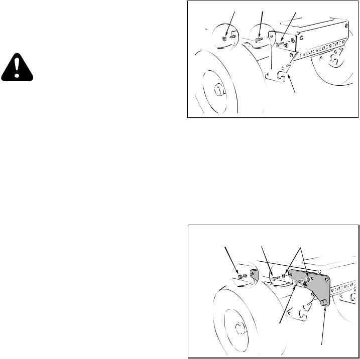
•Remove the hex bolt from the threaded hole at the top front corner of R.H. front suspension bracket.
•Remove either a or b depending on tractor:
a.the hex bolt from the threaded hole at the top rear corner of R.H. front suspension bracket.
b.the nut from the carriage bolt at the top rear corner of the bracket, leaving the carriage bolt in the tractor frame. See fi gure 1.
•Repeat for the L.H. front suspension bracket.
REMOVE NUT OR BOLT |
REMOVE BOLT |
FRONT SUSPENSION
BRACKET (R.H.)
FIGURE 1 |
RIGHT SIDE VIEW |
•Attach the front of the side plate to the threaded hole in the tractor frame using a 3/8" x 1" hex bolt and a 3/8" lock washer. Attach the rear of the R.H. side plate to the tractor using either a 3/8" x 1" hex bolt and lock washer or a 3/8" hex lock nut and lock washer. Repeat for the L.H. side. See fi gure 2.
NOTE: If the side plates are removed from the tractor frame, be sure to reassemble bolts and nuts back into the frame.
3/8" HEX |
OR 3/8" X 1" |
3/8" LOCK |
LOCK NUT |
HEX BOLT |
WASHER |
3/8" x 1" HEX BOLT
SIDE PLATE (R.H.)
FIGURE 2 |
RIGHT SIDE VIEW |
6
If you have a 54" mower deck go directly to page 8. All other deck sizes use the following instructions.
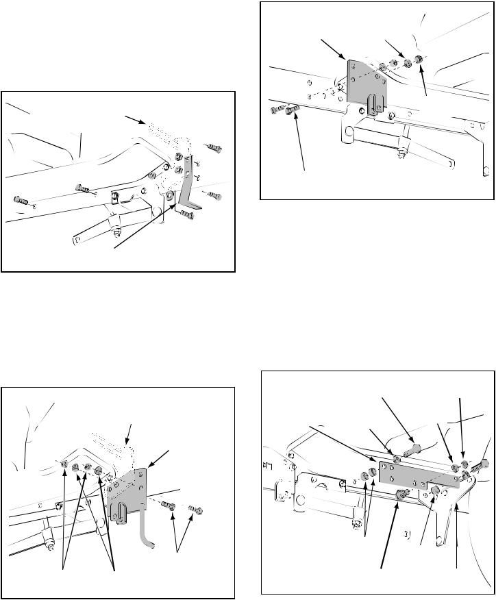
•Remove the mower stop bracket and its two bolts and nuts from the R.H. side of the tractor frame as shown in fi gure 3.
•If the tractor has a muffl er guard at the front of the R.H. foot rest, remove the bottom bolt and nut, and the washer which is located between the guard and the tractor frame. See fi gure 3.
•Remove the two bolts from the bottom of both the
R.H. and L.H. foot rests. See fi gure 3.
MUFFLER GUARD (ONLY MODELS WITH SIDE MUFFLER)
MOWER STOP
BRACKET
FIGURE 3 |
RIGHT SIDE VIEW |
•Assemble the R.H. hanger bracket to the bottom hole where the mower stop bracket was removed and to the upper hole under the front of the foot rest. Fasten with two 3/8" x 1" hex bolts, 3/8" lock washers and 3/8" hex lock nuts. (On tractors with muffl er guards, slide the hanger bracket between the guard and the tractor frame.) See fi gure 4.
MUFFLER GUARD (ONLY MODELS WITH SIDE MUFFLER)
R.H. HANGER
BRACKET
•Assemble the L.H. hanger bracket to the left side of the tractor frame using two 3/8" x 1" hex bolts, two 3/8" lock washers and two 3/8" hex lock nuts as shown in fi gure 5.
L.H. HANGER |
3/8" LOCK |
BRACKET |
WASHER |
3/8" HEX LOCK NUT
3/8" x 1" HEX BOLT
FIGURE 5 |
LEFT SIDE VIEW |
•Assemble a frame bracket to the L.H. foot rest and sway bar bracket as shown in fi gure 6. Use two 3/8" x 1-1/4" hex bolts, three spacers and two 3/8" lock washers.
•Assemble a shoulder bolt to the inside of the L.H. frame bracket, securing it with a 3/8" lock washer and a 3/8" hex lock nut. See fi gure 6.
•Repeat with a frame bracket on the R.H. side of the tractor. Attach in the same manner but use four spacers (two per bolt).
•Proceed to page 9.
|
3/8" x 1-1/4" |
3/8" HEX |
|
|
HEX BOLT |
LOCK NUT |
|
L.H. FRAME |
3/8" LOCK |
3/8" LOCK |
|
WASHER |
|||
BRACKET |
WASHER |
||
|
|
|
|
(2) SPACERS |
(1) SPACER |
|
|
|
3/8" x 1" |
|
||
|
|
|
|
|
|
|
|
HEX BOLT |
SHOULDER |
SWAY BAR |
|
3/8" HEX |
3/8" LOCK |
|
|||
|
BOLT |
|
BRACKET |
||
LOCK NUT |
WASHER |
|
|
||
|
|
|
|
||
FIGURE 4 |
|
RIGHT SIDE VIEW |
FIGURE 6 |
|
LEFT SIDE VIEW |
|
|
|
|
||
7
This page for tractors with 54" mower decks only.
•Remove and store the mower stop bracket and bolt from both sides of the tractor frame. See fi gure 3.
•Remove the two bolts from the bottom of the foot rests on both sides of the tractor frame. See fi gure 7.
54" MOWER DECKS
MOWER STOP
BRACKET
FIGURE 7 |
RIGHT SIDE VIEW |
•Assemble the 54" R.H. hanger bracket to the holes where the mower stop bracket was removed on the right side of the tractor frame. Fasten with two 3/8" x 1" hex bolts, two 3/8" lock washers and one 3/8" hex lock nut. See fi gure 8.
54" MOWER DECKS
3/8" HEX |
3/8" LOCK |
LOCK NUT |
WASHER |
|
R.H. HANGER |
|
BRACKET (54") |
|
3/8" x 1" |
|
HEX BOLT |
3/8" x 1" |
3/8" LOCK |
HEX BOLT |
WASHER |
FIGURE 8 |
RIGHT SIDE VIEW |
•Assemble the 54" L.H. hanger bracket to the holes where the mower stop bracket was removed on the left side of the tractor frame. Fasten with two 3/8" x 1" hex bolts, two 3/8" lock washers and two 3/8" hex lock nuts. See fi gure 9.
 ECKS
ECKS
L.H. HANGER
BRACKET (54")
3/8" x 1" HEX BOLT
|
3/8" LOCK |
3/8" HEX |
|
LOCK NUT |
|
|
WASHER |
|
|
|
|
FIGURE 9 |
|
LEFT SIDE VIEW |
•Assemble a frame bracket to the L.H. foot rest as shown in fi gure 10. Use two 3/8" x 1-1/4" hex bolts, four spacers (2 per bolt) and two 3/8" lock washers.
•Assemble a shoulder bolt to the inside of the frame bracket, securing it with a 3/8" lock washer and a 3/8" hex lock nut. See fi gure 10.
•Repeat with a frame bracket on the R.H. side of the tractor
54" MOWER DECKS
|
3/8" x 1-1/4" |
3/8" HEX |
|
|
HEX BOLT |
LOCK NUT |
|
FRAME |
3/8" LOCK |
3/8" LOCK |
|
WASHER |
|||
BRACKET |
WASHER |
||
|
(2) SPACERS
SHOULDER
BOLT
FIGURE 10 |
LEFT SIDE VIEW |
8
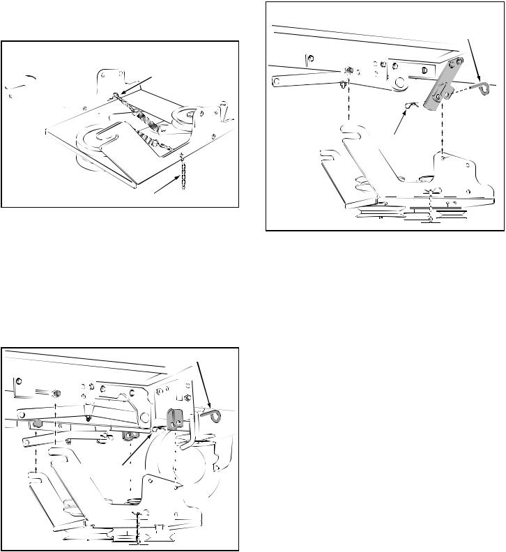
ATTACHING CLUTCH/IDLER ASSEMBLY
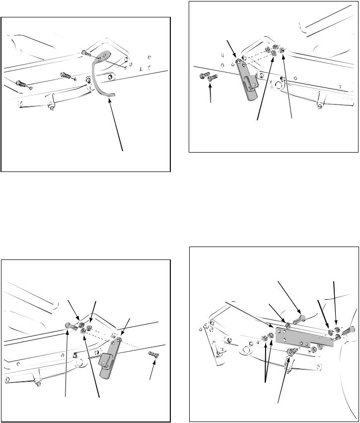
•Connect the end link of each chain to the springs shown in fi gure 11.
Use this paragraph if your mower deck is less than
48"
•If you have a mower deck smaller than 48", measure the outer diameter of the tractor's engine pulley. If the diameter of the pulley is less than 6",
move the inside hairpin clip in the L.H. adjusting chain from link #8 to link #5. (Links are counted from the end of the chain attached to the spring).
ENGINE PULLEYS LESS THAN 6" IN DIAMETER
LINK #5 IN
L.H. CHAIN
R.H. CHAIN
FIGURE 11
Use this paragraph if your mower deck is 48"
•Attach the rear of the clutch/idler assembly to the tractor frame by sliding the notched arms of the assembly onto the shoulder bolts assembled to the frame brackets. Lift the front of the assembly, positioning the upper idler pulley so that it clears the
engine pulley. Attach the front of the assembly to the hanger brackets using two pivot lock pins and two hairpin clips. See fi gure 12.
PIVOT LOCK PIN
HAIRPIN CLIP 
FIGURE 12 |
RIGHT SIDE VIEW |
Use this paragraph if your mower deck is 54"
•Attach the rear of the clutch/idler assembly to the tractor frame by sliding the notched arms of the assembly onto the shoulder bolts assembled to the frame brackets. Lift the front of the assembly, positioning the upper idler pulley so that it clears the
engine pulley. Attach the front of the assembly to the hanger brackets using two pivot lock pins and two hairpin clips. See fi gure 13.
TRACTORS WITH 54" MOWER DECKS ONLY
FIGURE 13
9
 Loading...