


536.885910
MANUAL
iCaution:
Read and Follow
_ All Safety Rules
and Instructions
i Before Operating
This Equipment
CRAFTSMAN®
8 HORSEPOWER
26" DUAL STAGE
TRAC-PLUS
120V. ELECTRIC START
SNOW THROWER
• Assembly
Operatzon
Maintenance
• Service and Adjustments
- RePair Parts
SEARS,. ROEBUCK AND CO., Chicago, IL 60684 ,U.S.A.
f . i r • n i| mini li : i i • i

SAFETY RULES
CAUTION: ALWAYS DISCONNECT SPARK PLUG WIRE AND PLACE A
WiRE WHERE IT CANNOT CONTACT SPARK PLUG TO PREVENT
ACCIDENTAL STARTING WHEN SE'I-I'ING-UP, TRANSPORTING,
ADJUSTING OR MAKING REPAIRS:
IMPORTANT
SAFETY STANDARDS REQUIRE OPERATOR PRESENCE CONTROLS TO MINIMIZE THE
RISK OF INJURY. YOUR SNOW THROWER IS EQUIPPED WITH SUCH CONTROLS. DO NOT
ATTEMPT TO DEFEAT THE FUNCTION OF THE OPERATOR PRESENCE CONTROL UNDER
ANY CIRCU MSTANCES.
BEFORE USE
• Read the Owner's Manual carefully. Be thor-
oughlyfamiliar with the controls arid the proper
use of the snow thrower. Know how to stopthe
show thrower and disengage the controls
quickly.
:o Do notoperatethesnowthrowerwithoutwear-
ing adequate winter outer garments. Wear
footwear that will improve footing on slippery
surfaces.
o Keepthe area ofoperation clearof all persons,
particularly small children, and pets.
• Thoroughly inspect the area where the snow
thrower isto be used and remove all doormats,
sleds, boards, wires, and other foreign objects.
• Use extension cords and receptacles as speci-
fied by the manufacturer for all .snow throwers
with electric drive motors or electdc starting
motors.
• Use only attachments and accessories ap-
provedbythe manufacturerofthesnowthrower
(such as tire chains, electdc start kits, etc.)
• Never operate the snow thrower without good
visibilityorlight. Always be sure of yourfooting,
and keep a firm hold on the handles. Walk;
never run.
• This snow thrower is for use on sidewalks,
driveways, and other ground level surfaces.
CAUTION should be exercised while using on
steep sloping surfaces. DO NOT USE SNOW
THROWER ON SURFACES ABOVE
GROUND LEVEL such as roofs of residences,
garages, porches or other such structures or
buildings,
• Check shear bolts and other bolts at frequent
intervals for proper tightness to be sure the
snow thrower is in safe working condition.
• Disengage all clutches and shift into neutral
before starting the engine.
• Adjust the snow thrower height to clear gravel
.... or crushed rock surface.
• _Let engine andsnow thrower adjust to outdoor
..... temperatures before starting to clear snow.
," '0
D
FUEL SAFETY
• Handle fuel with care; it is highly flammable.
• Use an approved fuel container.
• Check fuel supply before each use, allowing
space for expansion as the heat of the engine
and/or sun can cause fuei_to expand.
Fill fueltankoutdoorswith extreme care. Never
fill fuel tank indoors.
Replace fuel tank cap Securely and wipe up
spilled fuel.
• Never remove fuel tank cap or add fuel to a
running engine or hot engine.
= Never store fuel orsnowthrcwer with fuel inthe
tank inside of a building where fumes may
reach an open flame or spark.
OPERATING SAFETY
• _ Never allow children or young teenagers to
operate the snow throwerand keep them away
while it :is operating. Never allow adults to
operate ,the snow thrower without proper in-_
struction. Do not carry passengem.:
Always wear safety glasses or eye shields
• during operation orwhile performing an adjust,
ment or repair to protect eyes from foreign
objects that may be thrown from the snow
thrower.
• Exercise extreme caution when operating on
or crossing gravel ddves, walks, or roads. Stay
alert for hidden hazards or traffic.
• Do not put hands or feet near or under rotating
parts. Keep clear of the discharge opening at
all times.
Exercise caution to avoid slipping or falling, es-
pecially when operating in reverse.
Do not clear snow across the face of slopes.
Exercise caution when changing direction on
slopes. Do not attempt to clear steep slopes.
• Never operate the snow thrower withoutproper
guards, plates or other safety protective de-
vices in place ......
°
I
2
/i
• r:'
SAFETY RULES
• Never operate the snow thrower near glass
enclosures, automobiles, window wells, drop-
offs, and the like without proper adjustment of
' the snow discharge angle. Keep children and
pets away.
• .... Never operate the snow thrower at high trans-
port speeds on slippery surfaces. Look behind
and use care when backing.
• . Never directdischarge at bystanders or allow
- anyone in front of the snow thrower.
• Do not run the engine indoors, except when
starting the engine and for transporting the
snow thrower inor out of the building. Open the
= ,
outside doors; exhaust fumes are dangerous
.(containing CARBON MONOXIDE, an ODOR-
LESS and DEADLY GAS).
• Take all possible precautions when leaving the
........snow thrower unattended. Disengage the au-
:" ger/impeller, shift to neutral, stop erigine, and
• .: remove key .... ....
•-_ Do not overload the machine capacity by at-
tempting to clear snow at too fast a rate.
SAFE STORAGE
• Always refer toOwner's Manual instructions for
important details if the snow thrower is to be
stored for an extended period.
• Disengage power to the auger/impeller when
snow thrower is transported or not in use.
• Never store the snow thrower with fuel in the
REPAIRIADJUSTMENTS SAFETY
• After striking aforeign object, stop the engine
(motor), remove the wire from the spark plug,
disconnect the Cord on electric motors, thor-
=
oughly !nsPect the snow thrower for any dam-
age, _and.repair the damage before restarting
and Operating th_ snow thrower.
..e If the snow thrower should start to vibrate
abnormally, stop the engine (motor) and check
immediately for the cause. Vibration is gener-
" ally a warning of trouble.
• Stop the engine (motor) whenever you leave
the operating position before unclogging the
auger/impeller housing or discharge guide,
and when making any repairs, adjustments, or
inspections.
• When cle'aning, repairing, or inspecting, make
certain the auger/impeller and all moving parts
have stopped. Disconnectthe spark plug wire
and keep the wire away from the plug to pre-
-;ventaccidental Starting. " : -
• Never attempt to make any adjustmentswhile
the engine is running (except when specifically
recommended by.manufacturer,).
• Maintain or replace safety and instruction la-
bels, as necessary.
• Run the snow thrower a few minutes after
throwing snow to prevent freeze-up of the
auger/impeller- . •
fuel t_.nkinsideabuilding whereignition sources ........... '
are present such. as hot water and space ....:
• heaters, clothes dryers, and the like. Allow the .....
engine to cool before storing in any enc!osure .......
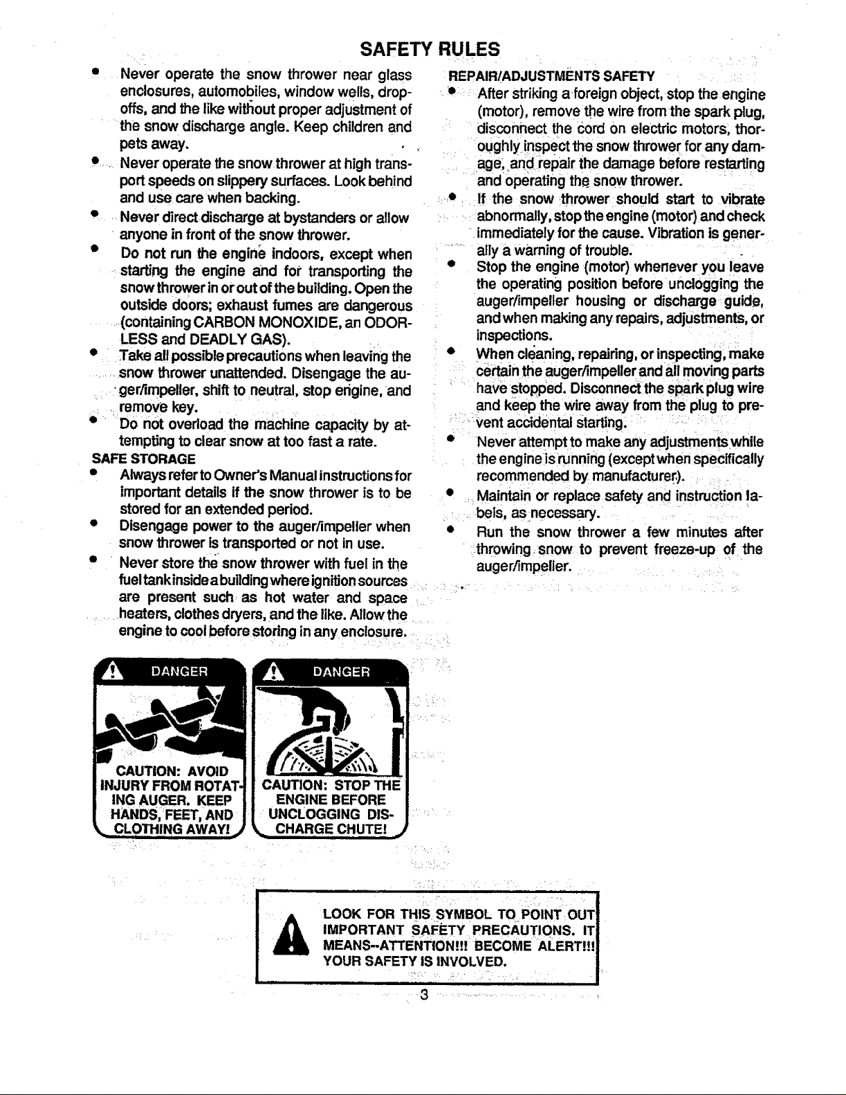
UNCLOGGING DIS-
i¸&
LOOK FOR THIS SYMBOL TOPOINT OUT
IMPORTANT SAFETY PRECAUTIONS. IT
MEANS--ATTE NTION!!! BECOME •ALERT!!!
YOUR SAFETY IS INVOLVED.
.... , , •
CONGRATULATIONS on your purchase of a Sears
CraftsmanSnow Thrower. tt has been designed;engi-
neered and manufacturedto give youthe best possible
dependabilityand performance.
Shouldyou experience any problem you cannot easily
remedy, please contact your nearest Sears Service
CenterlDepartrnent. We have competent, we,-trained
techniciansandthe propertoolstoservice orrepair this
unit.
PId_zseread andretainthis manual. The instructionswill
enableyoutorassembleand maintain yoursnowthrower
pr0pedy. .AIways observe the "SAFETY RULES."
MODEL
NUMBER 536.885910
SERIAL
NUMBER
DATE OF
PURCHASE.
THE MODELAND SERIAL NUMBERS WILL BE
FOUND ON A DECAL ATTACHED TOTHE REAR
OF THE SNOW THROWER HOUSING.
YOU SHOULD RECORD BOTH SERIAL NUMBER
AND DATE OF PURCHASE AND KEEP INA SAFE
PLACE FOR FUTURE REFERENCE.
MAINTENANCE AGREEMENT
A Sears Maintenance Agreement is available on this
product. Contactyournearest Sears Store for details.
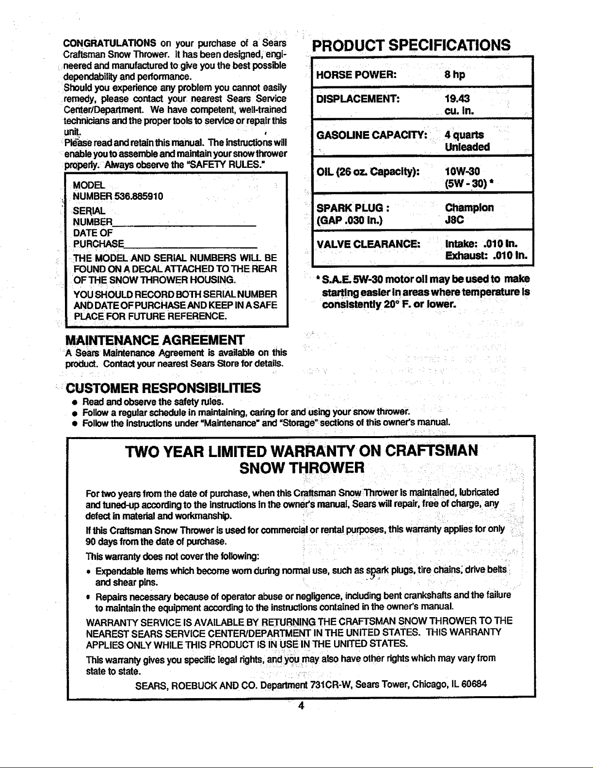
PRODUCT SPECIFICATIONS
HORSE POWER: 8 hp
DISPLACEMENT: 19.43
cu. in.
i JJ ,,
GASOUNE CAPACITY: = 4 quarts
_ Unleaded
III Ill i i iii
OIL (26 oz. Capacity): 10W-3O
(sw - 3o)*
i ii iiii
SPARK PLUG : Champion
(GAP .030 in.) J8C
H i
VALVE CLEARANCE: Intake: .010 In.
Exhaust: .010 In.
* S,A.E 5W-3O motor oi! may be used to make
start!ng easier in areas where temperature is
consistently 20° F. or lower.
-'=CUSTOMER RESPONSIBILITIES
• Read and observe the safety rules.
• Followa regularschedulein maintaining,cadngfor and usingyoursnow thrower.
• Followthe instructionsunder=Maintenance" and "Storage'sections of thisowner's manual.
i i ]i illilili 1 ii
TWO YEAR LIMITED WARRANTY ON CRAFTSMAN
SNOW THROWER
Fortwoyears fromthe date of purchase,when thisCraftsmanSnowThrower is maintained,lubricated
andtuned-up according to the instructionsinthe owner's manual, Searswill repair, free of charge, any
defectin material and workmanship.
Ifthis CraftsmanSnow Thrower is used forcommercial or rental purposes, this warranty appliesfor only _
90 daysfromthe date of purchase.
Thiswarrantydoes not coverthe following:
• Expendableitemswhichbecome worn duringnormal use, such as s__rk plugs,tire chains; drive belts
and shear pins.
= Repairs necessary because of operator abuse ornegligence,includingbent crankshaftsand the failure
to maintainthe equipmentaccordingto the instructionscontained inthe owner's manual.
WARRANTY SERVICE IS AVA1LABLEBY RETURNING THE CRAFTSMAN SNOW THROWER TO THE
NEAREST SEARS SERVICE CENTER/DEPARTMENT IN THE UNITED STATES. THIS WARRANTY
APPLIES ONLY WHILE THIS PRODUCT IS IN USE IN THE UNITED STATES.
Thiswarrantygives you specificlegalrights,and you may also have otherrightswhich may varyfrom
state to state. •.:
SEARS, ROEBUCK AND CO. Department731CR-W, Sears Tower, Chicago, IL 60684
,,,,,, ,, ,, iii i i i iiii ii iii
4
TABLE OFCONTENTS
SAFETY RULES ........................................ 2,3
PRODUCT SPECIFICATIONS ...................... 4
CUSTOMER RESPONSIBILITIES ............ ._4
WARRANTY.... ............................................. .4
TABLE OF CONTENTS .............................. -.5
INDEX ......................................... .................. 5
ASSEMBLY ................................................ 6-9
OPERATION .......................................... 10-15
MAINTENANCE ........................ 16-17
SERVICE AND ADJUSTMENTS ........... 18-24
STORAGE ................................................... 25
SERVICE RECOMMENDATIONS .............. 26
TROUBLE SHOOTING ............................... 27
REPA! RPARTS (SNOW TH ROWER)...28-36
REPAIR PARTS (ENGINE} .................... 37-40
PARTS ORDERING/SERVICE..... Back Cover
INDEX
A
Adjustment:
Auger ................ :................. ;.......... 19 •
Belt ...................... .:....................... 19
o
Belt Guide ......................... :21
Cable .................... ;........................ 19 :
Carburetor ..................................... 24
Fdctbn Wheel ................................ 2t
Spark Plug ..................................... 24
Track.............................................. 23
Tractionand Auger ........................ lg
Assembly:
F Operation:
Fuel, Type .................... ,......;.......4, 12 Engine Controls.......;L'.;10, 11, 13,14
Fuel, Storage ............... ...:;:..;,;..: 12, 25 _ Operating Snow Thrower...11, 12, 15
FrictionWheel: Operating Tips............................... 15
Adjustment.................................... 21 Starting the Engine, Electric .:........ 13
Replacement ................................. 22 Starting the Engine, Reoofl....L...... 14
G : Snow Thrower Controls ......... ;..10-12
Geam: Weight Transfer System ................ 12
AugerGear Box ...................... 16, 17
Hex Shaft ....................................... 16
H
Handle, Upper and Lower ................ 7
CrankAssembly ... ........................... 8 :::;.Headlight.; ....... ;.......;;;;;_.:.;_;:.;.;;;;.9. I0
Headlight ......................................... 9 " Height Adjust Skids ::::::::::::::::::::::: t8
ShifterLever ,.; ......;..........;;..;.:;.:;;;.9 ....... Hex Shaft. ......... :::;:.:.:.:::::::..:.:,.16, 17.....
Skid Height Adjustment ............. 7, 18 I
Unpacking........................................ 7
e ,
Belts:
Adjust Belts.....;:_.......;.:,................. 19
BeltGuide Adjustment................... 21
Belt Maintenance..: .......::::............. 16
Replace Belts .......................... ;20, 21
C
Cables,Clutch ........................... 7, 9, lg
Carburetor:.................................. 24,25 :: :
Ignition, Key.................... 10, 11, 13, 14
index ........_......................................... 5
L
Levers:
AugerDrive clutch ........7, 10, 11, 19
Choke ,. .............. ......... 10, 11, 13, 14
Sh_e_ ................................. 9, 10, 11
Throttle Control ...:........ 10, 11, 13, 14
TractionDrive Clutch ..:..7, 10, 11, 19
Lubrication:
P
Parts............................................ 28-40
Primer Button................. 10, 11, 13, 14
R
Repair/Replacement Parts .......... 28-40
Recoil Starter ...................... ;...:;....... 14
Replacements:
Auger Shear Bolt ....i ...................... 23
Belts......................................... 20, 21
FrictionWheel ............................... 22
S
Safety Rules.:.. ............................... 2, 3.
Service and Adjustments:
Auger Housing Height ............... 7, 18
•Auger Shear Bolt ........................... 23
Belts ......................................... 19-21
Belt Guide ....................... L..;......... .21
Chain _....:.:........... ;:,:::..:..: 16 •
Choke........;::::::::;:::::::;:::::....... I0,. 1I, 13
Clutch, Levers .......... :.......... ;;;.;;.10, 11
Controls:
Engine .:.:L._............LI" 10, 11,13, I4
Snow Thrower ............................... IO
Crank:
AdjustingRod ............................ 8, 18
Assembly......................................... 8
Operation....................................... 11
Customer Responsibilities.................. 4
Drive, Auger ....... ._............................ 11
Drive, Traction.;:,...... .................... 11
Deflector,Snow Chute ..................... 11
E.
Engine:
Control......................... 10, 11, 13, 14
Oil Cap ..................................... 12, 17
Oil Change ............................. ..,.. 17
Oil Level.....: .......... ;............:.:... 12, 17
Oil Type ............................... 4, 12, 17
Speed Governor ............................ 24
Starting,Electrically....................... 13
Starting,Manually .......................... 14
Storage.......................................... 25
Auger Gear Box............................ 17: :::i:Belt Replacements .......... ...;....20, 21
Auger Shaft ............... ;.............. 16, 26 Cable .............................. ...,.. 7, 9,_19
Chain and Sprockets ............... 16, 26 Carburetor............................... 24,25
Chart. ............................................ 26 FrictionWheel.......................... 21, 22
Engine ..................................... 12, 17 Spark Plug .......... :;......................... 24
Hax Shaft and Gears ..................... 16 Track .............................................. 23
: Weight Transfer System .......... 12, t6 Service Recommendations ............ 26
M : Spark Plug................................. 17,24
Maintenance: Specifications ..................................... 4
Agreement ....................................... 4 Speed Governor ........._,.................... 24
Auger Gear Box ................... .......... 17 Startingthe Engine:
Auger Shaft ......................... , ......... 16 Electric Start .._........._.................... 13
Chain and sprockets.......... _........... 16 ReCoilStart ...;................................ 14
Engine .................................. .........17- Stoppingthe Engine .......... ;..11, 13,14
General Recommendations ........... 16 Stopping the Snow Thlower ............ .11
Hex Shaftand Gears ..................... 16 Shipping Carton ............................. 6, 7
Weight Transfer System ................ 16 Skid Height .........................;..........7, 18
• O Shifter Lever................................. 9-11
Oil: Shear Bolts...................................... :23
Engine ................................ 4, 12, 17 Storage ............................................ 25
Extreme Cold Weather ......._...:.12,17 _ T
Storage :..... ..... .i.L._ .... _.........,..25 Table of Contents ..:..;.._................. ..5
Type.................................. 4, 12, 17 Trouble ShootingChart .................... 27
Tools for Assembly ....................... ._6
TractionDrive Belt .................... 19,21
Track Adjustment............................ 23
w
Warranty..;.. ......:.....;.............. :.........:_4
WeightTransfer System.......... 12,_18
,, ,,, LI i i
MBLY
i ii i H i, ,,, , •
THIS SNOW THROWER ISEQUIPPED WITH "TRAC-PLUS" AND ONLY
MOVES EFFECTIVELY WHEN ENGINE IS RUNNING
i
ffyoursnowthrower must be moved withoutthe aid of theengine, it willbe easier to pullthe snowthrower back-
wardbythe handles, ratherthan pushing.
OnstartUp,the trackdrive system may betightand wniloosenup as the _ow thrower is used. Alterfirstuse,
checkthe trackfor tension and adjust if necessary. See the Track Adjustmentparagraph in theService and Adjust-
mentssectionof this manual. Check trackadjustmentand fasteners regularly.
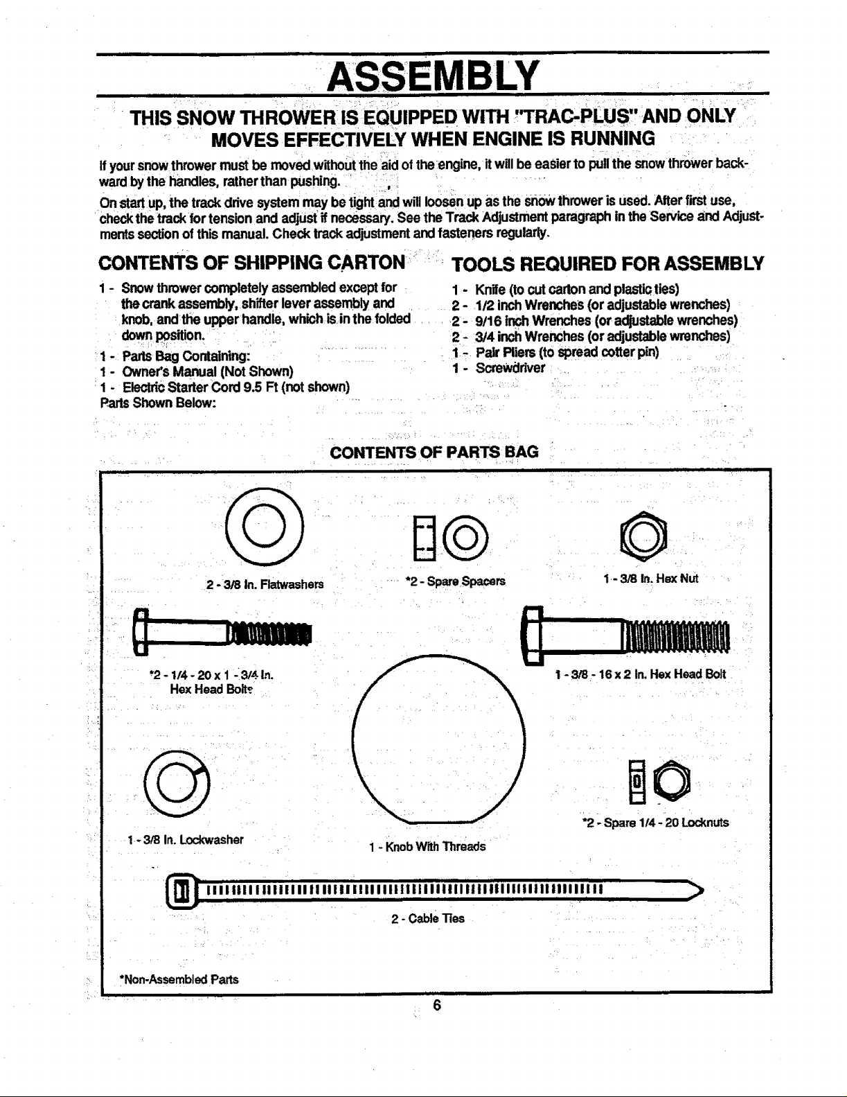
CONTE_S OF SHIPPING CARTON r,' TOOLS REQUIRED FOR ASSEMBLY
1-
PartsShown Below:
1 - Snowthrowercompletely assembledexcept for
thecrank assembly, shifterlever assembly and
knob, andrtheupper handle, whichis inthe folded
downposition.
PartsBag Containing:
Owner'sManual (Not Shown)
ElectdcStarter Cord 9.5 Ft (not shown)
1 - Knife (to cut cartonand plastiaties)
2 - 1/2 inchWrenches (or adjustablewrenches)
2- 9!16 inch Wrenches (or adjustablewrenches)
2- 3/4 inchWrenches (or adjustablewrenches)
1. Pair Pliers (to spread cotter pin)
1- ScreWdriver
2 - 3/8 in. Flatwashers
"2- 1t4-20x 1 _3!,$ In.
Hex Head Boit_
1-3/8 In. Lockwasher
CONTENTS OF PARTSBAG
ii , i |
*2 - Spare Spacers
II
1 - KnobWithThreads
©
1-3/8 In. Hex Nut
1-3/8 - 16x2 In. Hex Head Bolt
*2 - Spare 1/4 - 20 Locknuts
2 - Cablelies
>
*Non-Assembled Parts
6

FigureI showsthesnowthrowerintheshippingposition.
Figure2showsthesnowthrowercompletely assembled.
Reference to the right and left hand side of the sndw
thrower isfrom the operator'spositionat the handle.
TO REMOVE SNOW THROWER
FROM CARTON (See Fig 1)
• Removetop pallet and discard.
• Cut allfour comers ofthe carton from topto bottom
and lay the panelsfiat.
• Cut the cable ties attached to the auger.
• Cutanddiscardthe plastictiesthat securethecrank
assemblyand place the assemblyaside.
• Removethepackingmaterialfromthe controlpanel.
• Cut and discard the packing securing the clutch
cablesto the lowerhandle.
With two 9t16 inch wrenches, loosen (do not
remove) both bolts securingthe upper and lower
handles. Swingthe upperhandle intotheoperating
position.
NOTE: ifthe cables havebecome disconnectedfromthe
clutchlevers,reinstallthe cables as shown in Figure3.
• Tightenbothbolts securely.
Rollthe snowthroweroff the skid by pullingonthe
handle.
NOTE: This snowthrowerisequipped with a trackdrive
and can be hardto pushwhen the engine is notrunning.
Itiseasierto pullthe snowthrower backward ifitmustbe
moved withoutthe engine running.
The drive system may be tight when youfirstuse your
snowthrower. It loosensup as you use it.
HOW TO SET UP YOUR SNOW
THROWER
• Forpacking,the heightadjustskidswere mounted
with the bottom lip tumed inward. Remove skid
mounting nuts (Fig. 2) and remount withthe lip
outward.
To adjusttheskidheightfordifferent conditions,see
To AdjustSkidsHeights paragraph on page 18.
CAUTION: IF YOU ARE REMOVING
A SNOW FROM ANY ROCKY OR UNEVEN
SURFACES, RAISE THE FRONT OF THE
SNOW THROWER BY MOVING THE
SKIDS DOWN. THIS WILL HELP TO PREVENT
ROCKS AND OTHER DEBRIS FROM BEING
PICKED UP AND THROWN BY THE AUGER.
LOWER HANDLE
CRANK
CLUTCH
CABLE
FIG. 1
UPPER
HANDLE
. ASSEMBLY
FIG. 2
im i
DRIVE
LEVER
FIG. 3
7
BLY
I ] I i il IIIII mR ii
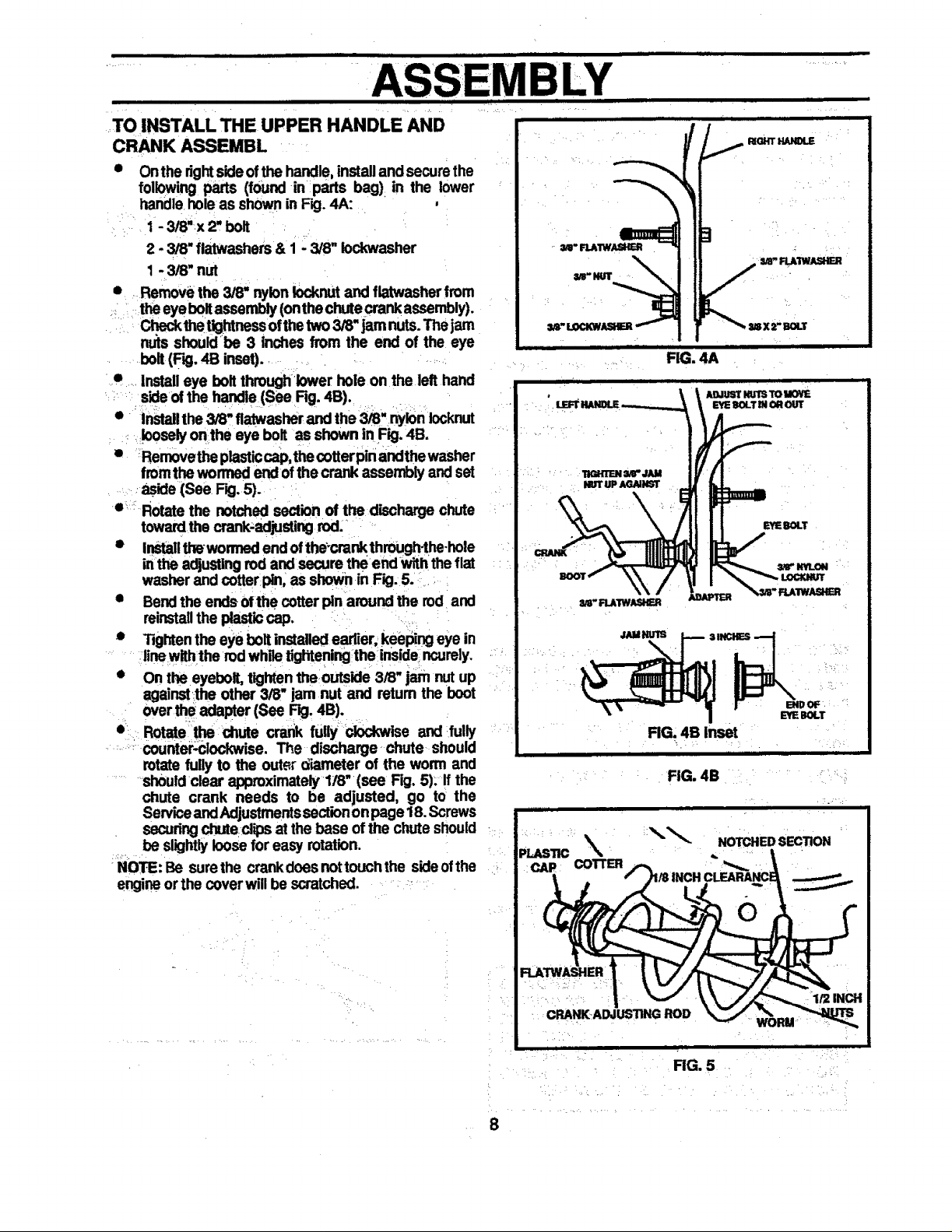
TO INSTALL THE UPPER HANDLE AND
CRANK ASSEMBL
Onthe rightsideofthe handle,installand securethe
following parts (found in parts bag) in the lower
handle hole as shown in Fig. 4A:
1 - 3/8"x 2, bolt
2 - 3/8" flatwashers & 1 - 3/8" iockwasher
1 - 3/8" nut
• Removethe 3/8" nylonlocknut and flatwasherfrom
theeyebolt assembly(onthechute crankassembly).
thetightnessofthe two 3/8" jam nuts.Thejam
nu_sshouldbe 3 inches from the end of the eye
bolt(RD,4B inset).
• Installeye bolt throughlower hole on the lefthand
sideof the handle (See Rg. 4B).
• Installthe 3/8" flatwasherand the 3/8" nylon Iocknut
looselyon the eye bolt asshown in Fig. 4B.
• _Rernovetheplasticcap,the cotterpin andthewasher
fromthe wormed endof thecrank assembly andset
aside (See Fig.5).
o_: Rotatethe notched section of the dischargechute
towardthe crank-adjustingrod.
• InStallthewommd end ofthe-crankthrough-the-hole
inthe adjustingrod and secure theend with the fiat
washer and cotterpin, as shownin Fig.5.
• Bendthe ends ofthe cotter pin around the rod and
reinstallthe plasticcap.
• Tightenthe eye boltinstalled earlier, keeping eye in
linewiththe rod while tighteningthe insidencure]y.
• Onthe eyebolt, tightentheoutside 3/8" jam nutup
agalnst_theother 3/8" jam nut and retum the boot
over the adapter(See Fig. 4B).
• Rotate the chute crank fully clockwise and fully
counter,clockwise. The discharge chute should
rotatefully to the outer diameter of the worm and
shouldclear approximately1/8" (see Fig. 5). If the
chute crank needs to be adjusted, go to the
ServiceandAdjustmentssectiononpage 18. Screws
securingchuteclips at the base ofthe chute should
be slightlyloosefor easy rotation.
NOTE: Be surethe crankdoes nottouchthe sideofthe
engineorthe coverwill be scratched.
i
_- RLAIWASHB_
I_OHT HANOLE
/
H
FIG. 4A
AO.IUSl"NUTSTO M(W_
gi OROUT
EYEBOLT
I ENOOF
Bile BOLT
FIG. 4B Inset
ii ii iii
FIG. 4B
RG. 5
8
, ,,ll j m Jl_q .||.n i i i i i n n, , ...........................
MBLY
III II IIIItl III lilt lilt III t t //i i i
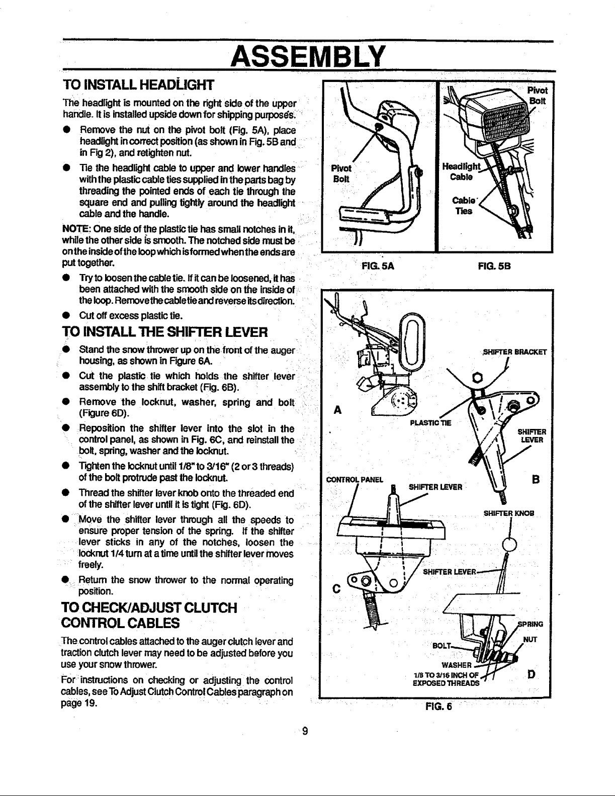
TO INSTALL HEADLIGHT
The headlightis mountedon the right side ofthe upper '
handle.Itis installedupsidedownfor shippingpurposdst'_
• Remove the nut on the pivot bolt (Fig, 5A), place
headlightincorrectposition(as shown inFig.5B and
in Fig 2), and retightennut.
• Tie the headlightcable to upper and lowerhandles
withtheplasticcabletiessuppliedinthe partsbagby
threading the pointed ends of each tie throughthe
square end and pullingtightlyaround the headlight -
cable and the handle.
NOTE: One sideof the plastictiehas small notchesin it,
whilethe otherside is smooth.The notchedsidemustbe
ontheinsideofthe Ioopwhichisformedwhentha endsare
put together,
• Tryto loosenthecabletie. ffitcanbe loosened,it has
been attachedwiththe smoothsideon the insideof_:
theloop.Removethecabletieandreverseitsdirection.
• Cut off excess plastictie.
TO INSTALL THE SHIFTER LEVER
Stand the snowthrower up on the,frontofthe auger
_ housing,as shownin Figure 6A.
• Cut the plastic tie which holds the shifter lever
assemblytothe shiftbracket(Fig. 6B).
• Remove the Iocknut, washer, spring and bolt
(Fkjure6D).
• ReposiUon the shifterleverintothe slotinthe
controlpanel,as shown inFig.6(3,and reinstallthe
bolt,spring,washerand thelocknut.
• TightenthelocknutuntilI/8"to3/16"(2or3 threads)
oftheboltprotrudepastthelocknut.
• Thread the shifterleverknobonto the threaded end
ofthe shifterleveruntilitis tight (Fig. 6D).
• Move the shitter lever through all the speeds to
ensure proper tension of the spring, tf the shifter
lever sticks in any of the notches, loosen the
Iocknut1t4turnatatime untgthe shifterlevermoves
freely.
e: Return the snow thrower to the normal operating
position.
TO CHECK/ADJUST CLUTCH
CONTROL CABLES
The contro!cablesattachedtotheaugerclutchleverand
tractionclutchlever may needto be adjustedbeforeyou
use yoursnow thrower.
Fort:instructionson checking or adjusting=the control
cables,see ToAdjustClutchControlCablesparagraphon
page 19.
RG. 5A FIG. 5B
r
A
PLASTICTIE
CONTROL PANEL
C
WASHER
1/S TO 3/16 INCH OF
EXPOSED THREADS
FIG. 6
SHmTER
LEVER
B
SHIFTER KNOB
D
9
• ii1•11 i i • i
........,................, OPERATION
THROWER .......
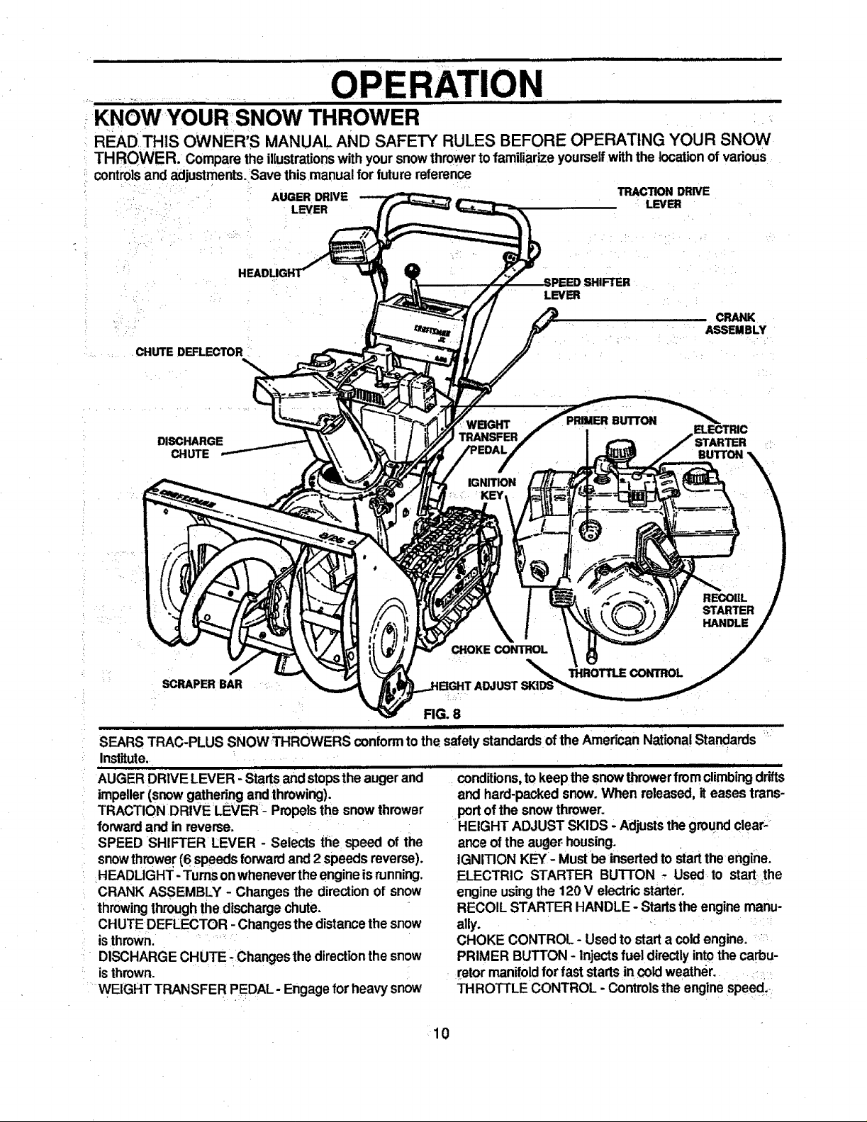
KNOWYOUR:SNOW
READ THIS OWNER'S MANUAL AND SAFETY RULES BEFORE OPERATING YOUR SNOW
TH ROWER. Compare the illustrationswith your snowthrowertofamiliarize yourselfwith the location of vadous
controls and adjustments. 'Save this manual for future r_emn_
AUGER DRIVE TRACTION DRIVE
.... i LEVER LEVER
LEVER
...... . CHUTE DEFLECTOR :
DISCHARGE
CHUTE
WBGHT
TRANSFER
IGNITION
KEY
PRIMER BUTTON
BUTTON
REOOIIL
STARTER
HANDLE
CHOKE CONTROL
SCRAPER BAR
THROTTLE CONTROL
FIG. 8
I IIJIItUI I • I I 111111111 I
SEARS TRAC-PLUS SNOWTHROWERS conformtothe safety standardsof the American National Standards
Institute. L _ .......
ii LIL
AUGER DRIVE LEVER - Startsandstopsthe augerand
impeller(snowgathering andthrowing).
TRACTION DRIVE LEVER - Propelsthe snow thrower
forwardand in reverse.
SPEED SHIFTER LEVER - Selects the speed of the
snowthrower(6 speeds forwardand 2 speeds reverse).
HEADLIGHT -Turns onwheneverthe engineis running.
CRANK ASSEMBLY - Changesthe directionof snow
throwingthroughthedischargechute.
CHUTE DEFLECTOR - Changesthe distancethe snow
isthrown. :
• DISCHARGE CHUTE :Changes the direction the snow
is thrown.
" WEIGHTTRANSFER PEDAL- Engage for heavy snow
i i iron f i
conditions, to keep the snowthrowerfromclimbing drifts
and hard-packedsnow. When released, it eases trans-
portofthe snowthrower.
HEIGHT ADJUST SKIDS - Adjuststhegroundclear-
ance of the auger housing.
IGNITION KEY- Mustbe insertedto start the engine.
ELECTRIC STARTER BUTTON - Used to start;the
engine usingthe 120 V electricstarter.
RECOIL STARTER HANDLE - Starts the engine manu-
ally. *
CHOKE CONTROL - Used to start a cold engine.
PRIMER BUTTON - Injectsfuel directlyintothe carbu-
retormanifoldforfast starts in cold weather.
THRO'I-rLE CONTROL -Controlsthe enginespeed,
10
H
i |11 i ui , i1| iii iii i
• OPERATION
lUL III1"I........
The operationofanysnowthrowercanresultinforeign objectsbeingthrownintothe
eyes, which can resultinsevere eye damage. Alwayswear safety glasses or eye
shieldswhile operatingthe:snow thrower.
We recommend standardsafety glasses or wide visionsafety mask for over your
glasses available at SEARS Retail or Catalog Stores.
HOW TO USE YOUR SNOW
THROWER
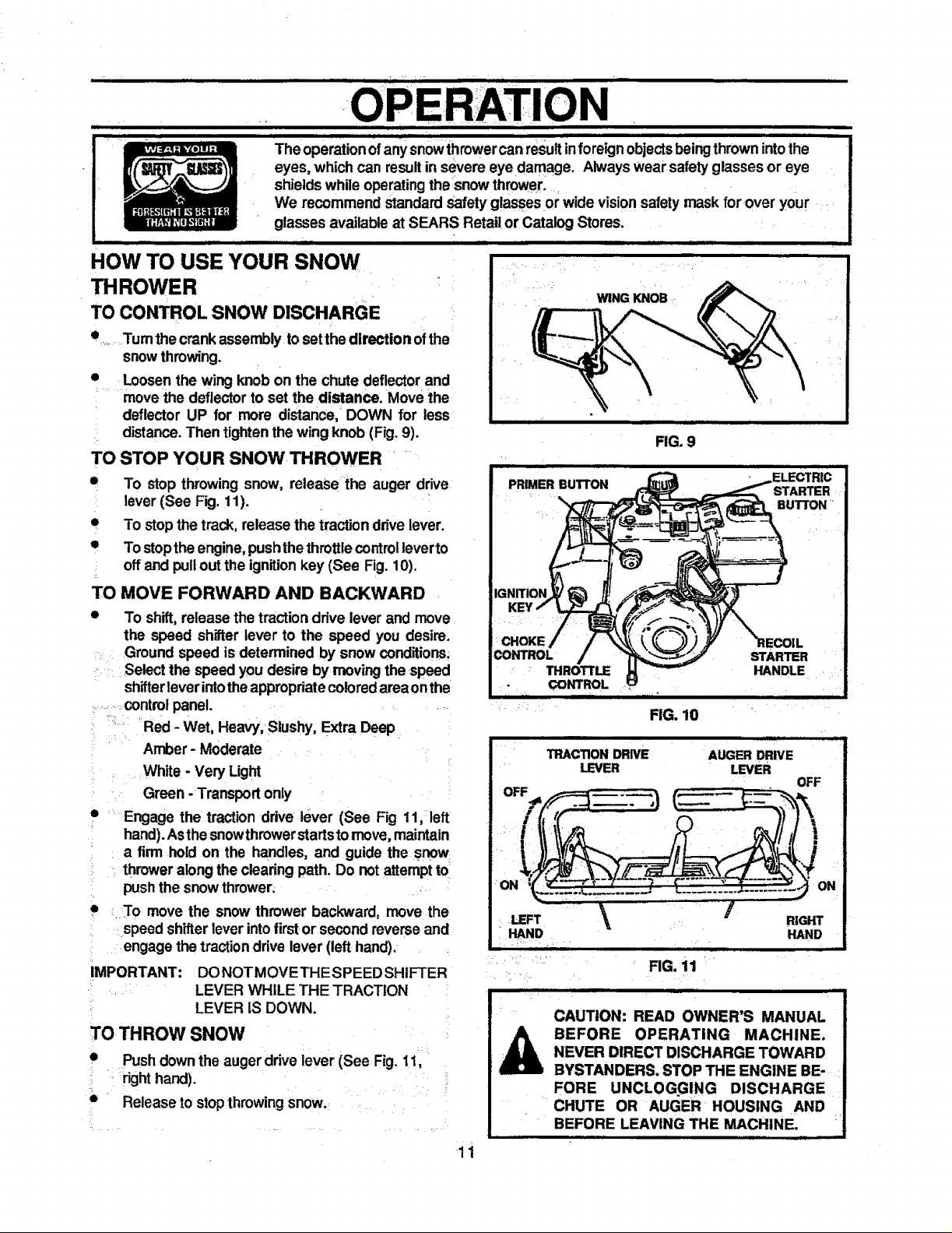
TO CONTROL SNOW DISCHARGE
Tum the crank assembly to setthe direction ofthe
snowthrowing.
e
Loosenthe wing knob on the chute deflectorand
.... movethe deflectorto set the distance. Move the
deflector UP for more distance, DOWN for less
distance. Then tightenthe wing knob (Fig. 9).
TO STOP YOUR SNOW THROWER
• To stop throwing snow, release the auger drive
lever (See Fig. 11).
• To stopthe track, release the traction drivelever.
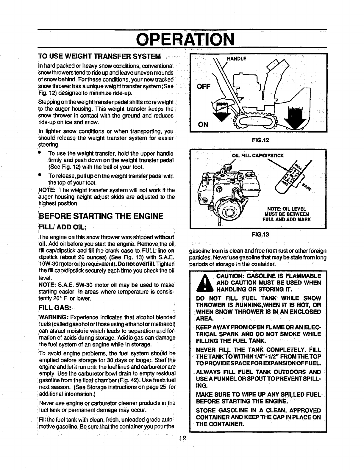
• To stopthe engine, pushthethrottlecontrol leverto
: offand pullout the ignitionkey (See Fig. 10).
TO MOVE FORWARD AND BACKWARD
• To shift, release thetraction drive lever and move
the speed shifter lever to the speed you desire.
Ground speed is determined by snow conditions;
= Select the speed you desire by movingthe speed
shifterleverintotheappropriatecoloredarea onthe
...........controlpanel. =
,-°, , = ,
'.... Red - Wet, Heavy; Slushy, Extra Deep
Amber - Moderate
White - Very Light
= Green -Transport only
. Engage the tractionddve lever (See Fig 11, left
• hand).Asthe snowthrowerstartstomove,maintain
a firm hold on the handles, and guide the snow
, : thrower alongthe clearing path. Do not attemptto
push the snowthrower;
i
• . To move the snow thrower backward, move the
speed shifter leverintofirstor secondreverse and
engage thetractiondrive lever (left hand).
IMPORTANT: DONOTMOVETHESPEED SHIFTER
. . LEVER WHILE THE TRACTION
LEVER IS DOWN.
TO THROW SNOW
• Pushdownthe auger drive lever (See Fig. 11,
: . right hand).
°
• Release to stopthrowingsnow.
[
WING KNOB
FIG, 10
i JLWULI = I I 1_
TRACTION DRIVE AUGER DRIVE
LEVER LEVER
OFF
ON ON
.LEFT _ RIGHT
HAND HAND
iii r • ii
FIG. 11
CAUTION: READ OWNER'S MANUAL
BEFORE OPERATING MACHINE.
NEVER DIRECT DISCHARGE TOWARD
BYSTANDERS. STOP THE ENGINE BE-
FORE UNCLOGGING DISCHARGE
CHUTE OR AUGER HOUSING AND
BEFORE LEAVING THE MACHINE,
11
! • • , ,, ,-,, , i,ii i , , , , ,
OPERATION
. i1.11 Hi| i = i
° .
i
HANDLE
TO USE WEIGHT TRANSFER SYSTEM
In hard packedor heavy snow conditions,conventional
snowthrowerstendto rideupandleave unevenmounds
ofsnowbehind. Forthese conditions, your new tracked
snowthrowerhasa uniqueweighttransfer system(See '_
Fig. 12) designedto minimize ride-up.
Steppingonthe weighttransferpedalshiftsmoreweight
to the auger housing.This weight transfer keeps the
snow thrower in contact with the ground and reduces
ride-upon ice and snow.
in lighter snow conditions or when transporting, you
Shouldrelease the weight transfer system for easier
steering.
• To use theweighttransfer,holdthe upperhandle
firmlyand pushdown on theweighttransferpedal
(SeeFig.12)withtheballofyourfoot.
• To release,pullupon theweighttransferpedalwith
thetopofyourfoot.
NOTE: The weighttransfersystemwillnotwork ifthe
augerhousingheightadjustskidsareadjustedtothe
highestposition.
!BEFORE STARTING THE ENGINE
FILL/ADD OIL:
The engineon thissnow throwerwas shippedwithout
oil. Addoilbeforeyou start the engine. Remove the oil
fillcap/dipstickand fill the crank case to FULL lineon
dipstick (about 26 ounces) (See Fig. 13) with S.A.E.
_10W-30motoroil(orequivalent).Do notoverfULTighten
thefillcap/dipsticksecurelyeach time you checkthe oil
level.
NOTE: S.A.E. 5W-30 motor oil may be used to make
starling easier in areas where temperature is consis-
tently20° F. or lower.
FILL GAS:
WARNING: Experience indicatesthat alcohol blended
fuels(calledgasoholorthoseusingethanolor methanol)
can attract moisturewhich leadsto separationand for-
marion of acids during storage. Acidicgas candamage
thefuel system of an enginewhile in storage.
To avoid engine problems,the fuel system should be
emptiedbefore storagefor 30 days or longer. Startthe
engineand letitrununtilthe fuel linesand carburetorare
empty. Use the carburetorbowldrain to emptyresidual
gasoline from the floatchamber (Fig. 42), Use fresh fuel
nextseason. (See Storageinstructionson page 25 for
additionalinformation.)
Never use engineor carburetorcleane_'productsinthe
fuel tank or permanent damage may occur. !
Filtthefuel tankwithclean,fresh, unleaded grade auto:
:motive gasoline.Be surethat the container youpourthe
t2
OFF
ON
i
FIG.12
OIL FILL CAWDIF_STICK
NOTE: OIL LEVEL
MUST BE BETWEEN
FULL AND ADD MARK
| i
RG.13
gasolinefrom isclean andfree fromrustor otherforeign
)articles.Neveruse gasolinethatmay bestale from long
)eriodsof storage in the container,
i i i H
A CAUTION: GASOLINE IS FLAMMABLE
AND CAUTION MUST BE USED WHEN
HANDLING OR STORING IT.
DO NOT RLL FUEL TANK WHILE SNOW
THROWER IS RUNNING,WHEN IT IS HOT, OR
WHEN SNOW THROWER IS IN AN ENCLOSED
AREA.
KEEP AWAY FROM OPEN FLAME OR AN ELEC-
TRICAL SPARK AND DO NOT SMOKE WHILE
RLLING THE FUEL TANK.
NEVER FILL THE TANK COMPLETELY. FILL
THE TANKTOWITHIN 1/4 '- 112"FROMTHE TOP
TO PROVIDE SPACE FOR EXPANSION OF FUEL.
i ALWAYS FILL FUEL TANK OUTDOORS AND
USE A FUNNEL OR SPOUT TO PREVENT SPILL-
ING.
MAKE SURE TO WIPE UP ANY SPILLED FUEL
BEFORE STARTING THE ENGINE.
STORE GASOLINE IN A CLEAN, APPROVED
CONTAINER AND KEEP THE CAP IN PLACE ON
THE CONTAINER.
TO STOP ENGINE
uw]_wl i i
PRIMER BUTTON
• To stop engine, move the throttle control lever to
STOP positionand remove key, Keep the key in a
safe place.The enginewill notstartwithoutthe key."
TO START ENGINE (Electric Starter)
Be sure that the engine has sufficientoil. The snow,
thrower engine isequippedwith a 120 voltA.C. electdc =
starter and recoilstarter. Beforestartingthe engine,be
certainthat you have read the following information:
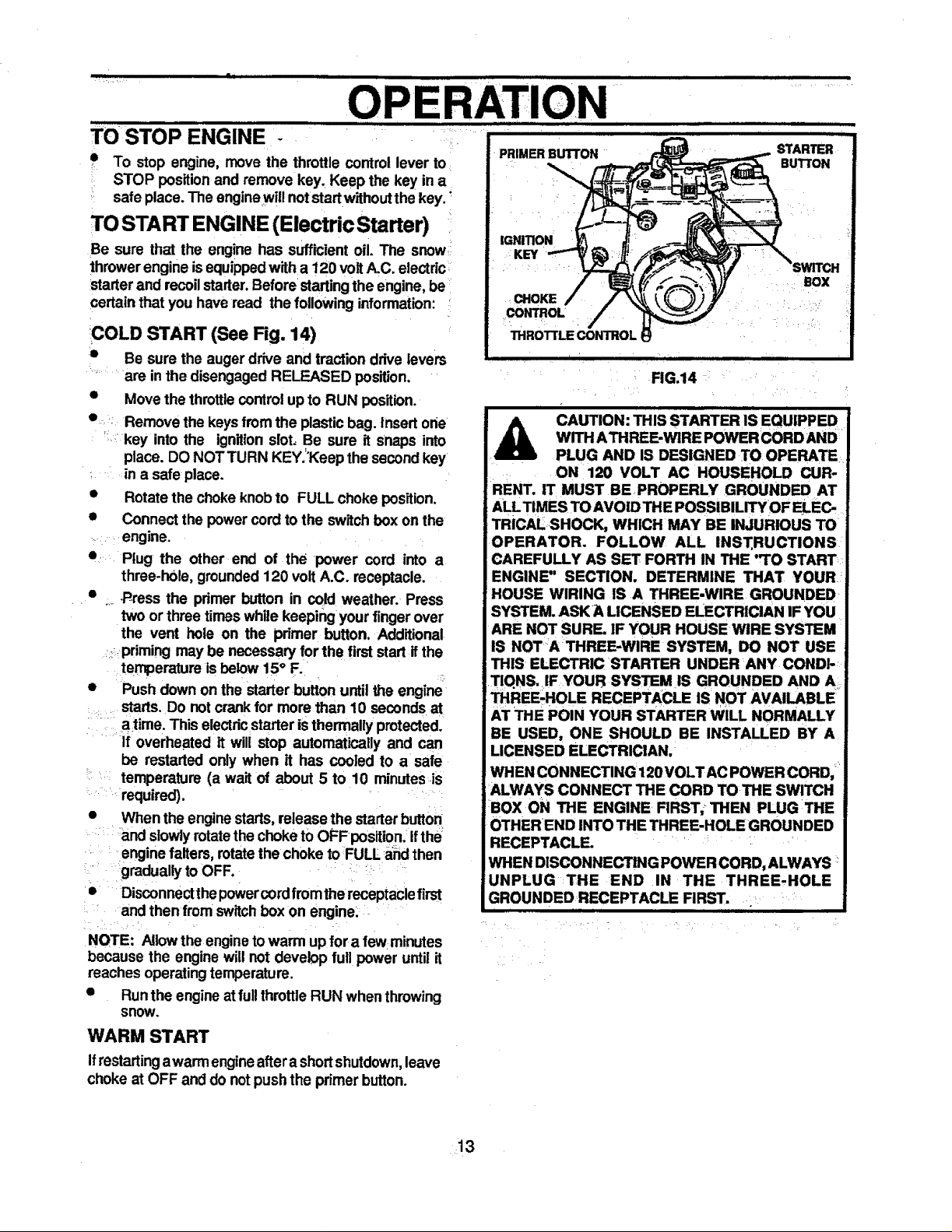
COLD START (See Fig. 14)
s Be sure the auger drive and traction drive levers
are in the disengaged RELEASED position.
• Movethe throttlecontrol upto RUN position.
• Remove the keys fromthe plasticbag. Insert one
key into the ignitionslot=Be sure it Snaps into
place. DO NOT TURN KEY.='Keepthe secondkey
in a safe place.
• Rotatethe choke knobtO FULL choke position.
• Connect the powercordto the switchbox onthe
engine.
• Plug the other end of the power cord into a
three.h01e,grounded120 volt A.C. receptacle.
• ._ .P_ressthe primer button in cold weather. Press
two or three timeswhile keeping your fingerover
the vent hole on the primer button. Additional
priming may be necessary for the firststartif the
temperature is below 15° F.
• Push down on the starterbutton until the engine
starts. Do notcrank for more than 10 seconds at
atime. This electricstarter isthermallyprotected.
If overheated it will stop automatically and can
be restarted only when it has cooled to a safe
temperature (a wait of about 5 to 10 minutes=is
required).
• When the enginestarts,release the starter button
and slowlyrotatethe choketo OFFpositlon. ifthe
enginefalters, rotatethe choke to FULL and then
graduallyto OFF. •
• Disconnectthepowercordfrom the receptaclefirst
and then fromswitchbox on engine:
IGNITION
KEY
CHOKE
CONTROL
THROTTLE CONTROL
nnnunnn|ul
FIG.14
mnn
n u,__
STARTER
BUTTON
BOX
,,,,,, ,,, • i
CAUTION: THIS STARTER IS EQUIPPED
WITH ATHREE-WIRE POWER CORD AND
PLUG AND IS DESIGNED TO OPERATE
ON 120 VOLT AC HOUSEHOLD CUR-
RENT. IT MUST BEPROPERLY GROUNDED AT
ALLTIMES TO AVOID THE POSSIBILITY OF ELEC=
TRICALSHOCK, WHICH MAY BE INJURIOUS TO
OPERATOR. FOLLOW ALL INST.RUCTIONS
CAREFULLY AS SET FORTH IN THE "TO START
ENGINE" SECTION. DETERMINE THAT YOUR
HOUSE WIRING IS A THREE-WIRE GROUNDED _
SYSTEM. ASK A LICENSED ELECTRICIAN IF YOU
ARE NOT SURE. IF YOUR HOUSE WIRE SYSTEM
IS NOTA THREE-WIRE SYSTEM, DO NOT USE
THIS ELECTRIC STARTER UNDER ANY CONDI-
TIQNS. IF YOUR SYSTEM IS GROUNDED AND A
THREE-HOLE RECEPTACLE IS NOT AVAILABLE
AT THE POIN YOUR STARTER WILL NORMALLY
BE USED, ONE SHOULD BE INSTALLED BY A
LICENSED ELECTRICIAN,
WHEN CONNECTING 120VOLTAC POWER CORD,
ALWAYS CONNECT THE CORD TO THE SWITCH
BOX ON THE ENGINE FIRST, THEN PLUG THE
OTHEREND INTO THE THREE-HOLE GROUNDED
RECEPTACLF--
WHEN DISCONNECTING POWER CORD, ALWAYS
UNPLUG THE END IN THE THREE-HOLE
GROUNDED RECEPTACLE FIRST.
i i
NOTE: Allowthe engineto warm up for a few minutes
because the engine will not develop full power until it
reaches operatingtemperature.
• Runthe engineatfullthrottleRUN whenthrowing
snow.
WARM START
Ifrestartingawarm engineaftera shortshutdown,leave
choke at OFF and do notpush the primer button.
13
CAUTION: NEVER RUN ENGINE IN-
A DOORS ORIN ENCLOSED, POORLY
VENTILATED AREAS. ENGINE EX-
HAUST CONTAINS CARBON MON-
OXIDE, AN ODORLESS AND DEADLY GAS.
KEEP HANDS, FEET, HAIR AND LOOSE
CLOTHING AWAY FROM ANY MOVING PARTS
ON ENGINE AND SNOW THROWER.
WARNING: TEMPERATURE OFMUFFLER AND
NEARBY AREAS MAY EXCEED 150° F. AVOID
THESE AREAS.
DO NOT ALLOW CHILDREN OR YOUNG TEEN-
AGERS TO OPERATE OR BE NEAR SNOW
THROWER WHILE IT IS OPERATING.
I I I I
RATION
,i,
CHOKE
CONTROL
rT(
• To stop engine; move the throttle control lever to
STOP positionand removekey. Keep the key in a
Safe place. The enginewillnot start withoutthe key.
TO START ENGINE (Recoil Starter)
Besurethattheenginehassufficientoil. Beforestarting
-the engine, be certain that you have read the following
information:
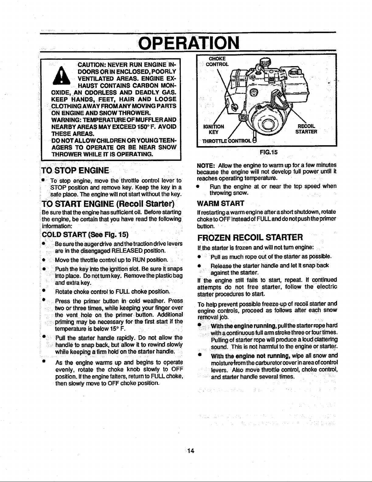
COLD START (See Fig. 15)
• Besurethe augerdrive andthe tractionddve levers
are in the disengagedRELEASED position.
Move the throttlecontrolup to RUN position.
Push the key intothe ignitionslot.Be sure it snaps
intoplace. Donotturnkey. Removethe plasticbag
and extra key.
Rotate choke controlto FULL choke position.
Press the primer button in cold weather. Press
twoor three times, whilekeeping yourfinger over
the vent hole on the primer button. Additional
pdrningmay be .necessary for the firststart ifthe
temperature is below15° F.
Pull the starter handle rapidly, Do not allow the
....handle to snap back, but allow it to rewind slowly
while keeping a firm holdonthe starter handle:
As the engine warms up and begins to operate
evenly, rotate the choke knob slowly to OFF
position.Ifthe enginefalters, returnto FULL choke,
then slowlymoveto OFF choke position.
i illl
KEY
THROTTLE
FIG.15
RECOIL
STARTER
NOTE: Allowthe engine towarm upfor a few minutes
because the engine will not develop full power until it
reachesoperatingtemperature.
• Run the engine at or near the top speed when
throwing snow.
WARM START
Ifrestartingawarm engineaftera shortshutdown,rotate
choketoOFF insteadofFULL anddonotpushtheprimer
button.
FROZEN RECOIL STARTER
if the starter is frozen and will notturnengine:
• Pull as muchrope out of the Starteras possible.
• Release the starter handle and letitsnap back
• against the starter.
If the engine still fails to start, repeat. If continued
attempts do not free starter, foliQw the electric
starterproceduresto start.
To helpprevent possiblefreeze-up of recoilstarter and
engine controls, proceed as follows after each snow
removaljob.
• _ Withthe engine running, pullthe starterropehard
withacontinuouslull armstrokethreeorfourtimes.
Pullingof starterropewillproducea loudclattering
sound. This isnot harmfultothe engineor starter.
• With the engine not running, wipe all snow and
moisture_rom the carburetorcoverinareaofcontrol
levers; Also move throttle control, choke control,
and starterhandle several times.
 Loading...